1
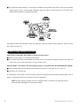
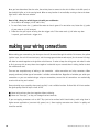
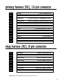
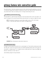
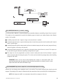
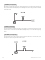
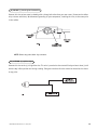
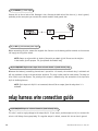
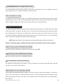
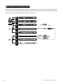
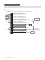
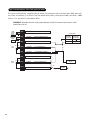
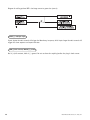
plug-in harnesses
super bright LED, 2-pin white plug
The super bright LED operates at 2V DC. Make sure the LED wires are not shorted to ground as the LED will be
damaged. Multiple LED’s can be used, but they must be wired in series. The LED fits into a 9/32 inch mounting
hole. Be sure to check for clearance prior to drilling the mounting hole.
valet/program switch, 2-pin blue plug
The Valet®/Program switch should be accessible from the driver’s seat. It plugs into the blue port on the side of
the unit. Since the system features Valet® by using the remote transmitter, the switch can be well hidden.
Consider how the switch will be used before choosing a mounting location. Check for rear clearance before drilling
a 9/32-inch hole and mounting the switch.The GRAY wire in the two-pin plug may also be used as a (+) ghost
switch input and can be connected to any (+) switch in the vehicle. (See Feature Descriptions section of this
guide.)
programmer interface, 3-pin black plug
The black three pin port is provided for personal computer programming of the unit. When using the DEI Bitwriter
(P/N 998T) or optional PC Interface module (P/N 996T) it is possible to configure any and all of the programmable functions using an IBM-compatible personal computer. For more information please refer to the guide
packaged with the programmer. This port can also be used to interface the Valet® Car★Com (DEI P/N 820T) with
the security system.
shock sensor harness, 4-pin connector
GREEN (-) multiplex input
Inputs shorter than 0.8 seconds will trigger the Warn Away® response, while inputs longer than 0.8 seconds will
trigger full alarm sequence and report zone four. If installing an optional DEI® dual stage sensor, connect to the
green wire as shown below. The diagram below eliminates the need for diodes to isolate the sensors, as well as
providing a separate zone for each sensor.
© 1999 Directed Electronics, Inc. Vista, CA
25