1
Installation ◆ Cable Connections
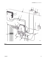
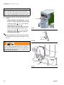
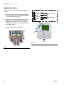
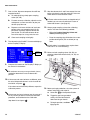
4. Route the opposite Fiber Optic Cable end through
the Smart Fluid Panel strain relief connector
(D). FIG. 15. Do not route the cable with tight bends
or kinks.
The fiber optic cable has a minimum bend radius of
1.6 in. (40 mm).
6. Tighten the strain relief connector
Connect Operator Station to
Smart Fluid Panel
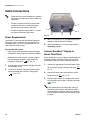
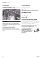
The Operator Station cable (F) is factory wired into the
Operator Station. FIG. 17. Do not disconnect the cable
except to replace it. Route the 50 ft. (15.2 m) cable to
the Smart Fluid Panel and connect it to the Operator
Station connector
B
(D). FIG.
16.
(G). FIG. 15.
G
D
F
FIG. 15
FIG. 17
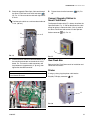
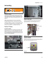
5. Connect the blue and black cable connectors (E) to
Gun Flush Box
the matching connectors on the electrical circuit
board. FIG. 16. Insert the cable connectors until
they bottom out (approximately ¼” [6 mm]), then
tighten the threaded connector.
CAUTION
Do not over-tighten or cause excessive stress on the
circuit board connector.
Refer to the Gun Flush Box manual for installation and
connection instructions.
Printer
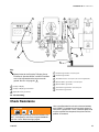
If using a printer, plug the printer cable into the
EasyKey™ Display connector
(H).
H
E D
FIG. 18
FIG. 16
310633C
21