1
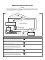
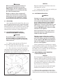
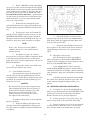
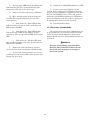
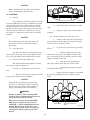
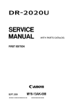
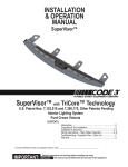
Price $15.00
PREMIUM VISION® SL LED LIGHTBAR
INSTALLATION AND MAINTENANCE INSTRUCTIONS
LIMITED WARRANTY
The Signal Division, Federal Signal Corporation (Federal), warrants each
new product to be free from defects in material and workmanship, under
normal use and service, for a period of two years on parts replacement and
one year on labor from the date of delivery to the first user-purchaser.
During this warranty period, the obligation of Federal is limited to repairing or replacing, as Federal may elect, any part or parts of such product
which after examination by Federal discloses to be defective in material
and/or workmanship.
Federal will provide warranty for any unit which is delivered, transported
prepaid, to the Federal factory or designated authorized warranty service
center for examination and such examination reveals a defect in material
and/or workmanship.
This warranty does not cover travel expenses, the cost of specialized equipment for gaining access to the product, or labor charges for removal and
re-installation of the product. Lamps, flash tubes, or batteries are not
covered under warranty.
This warranty does not extend to any unit which has been subjected to abuse,
misuse, improper installation or which has been inadequately maintained,
nor to units which have problems relating to service or modification at
any facility other than the Federal factory or authorized warranty service
centers.
THERE ARE NO OTHER WARRANTIES, EXPRESSED OR IMPLIED,
INCLUDING BUT NOT LIMITED TO, ANY IMPLIED WARRANTIES OF
MERCHANTABILITY OR FITNESS FOR A PARTICULAR PURPOSE. IN
NO EVENT SHALL FEDERAL BE LIABLE FOR ANY LOSS OF PROFITS
OR ANY INDIRECT OR CONSEQUENTIAL DAMAGES ARISING OUT
OF ANY SUCH DEFECT IN MATERIAL OR WORKMANSHIP.
IMPORTANT WIRING CHECK LIST
WARNING
The Premium Vision® warning system is an advanced microprocessor based warning system. Unlike conventional
light bars, malfunctions and/or improper operation WILL result if proper installation procedures are not followed.
Refer to the accompanying diagram and pay special attention to the “DO & DON’T” list at the bottom of this page. To
complete the electrical installation, refer to paragraph 3-7.
PREMIUM VISION SL
WARNING SYSTEM
R
-
+
RED + 10AWG
CONTROL CABLE RJ45 (8)
BLK - 10AWG
CONTROL HEAD
RJ11 (4)
AMPLIFIER/RELAY UNIT
SWITCHED IGNITION LINE CAPABLE
SIREN
* OF CARRYING AN ADDITIONAL 2A
+ BAT
A
12
11
10
9
8
7
6
3
5
2
B
C
D
4
BLK
RELAY SWITCHED POWER
TO AUXILIARY DEVICES
CIRCUIT BREAKER
RED + 10AWG (MIN.)
AUXILIARY RELAY & SIREN POWER
50 AMP
50 AMP
1
GRN
RED
2 AMP
VEHICLE CHASSIS
FUSE BLOCK
- NEG
*
POS +
VEHICLE BATTERY
CHASSIS GROUND, AT FUSIBLE
LINK ON FRONT FENDER.
CHECK LIST
1.
Is the 10 ga. red wire from the lightbar connected to one of
the two 50-ampere circuit breakers (installed as close to the battery as possible and directly to the positive (+) battery terminal)?
YES
2.
Is the 18 ga. red wire from the twelve pin connector (Pin 6)
connected to a point on the fuse block that is powered in run and
start positions? Use an in-line 2A fuse.
YES
3.
Is the 10 ga. black wire from the lightbar AND the 14 ga.
black wire from the twelve pin Molex connector (Pin 4) connected
to the fusible link at the front fender between the negative (-)
battery terminal and chassis ground? This is the ONLY chassis
ground allowed for these two wires.
YES
4.
Is the green wire from the twelve pin Molex connector (Pin
5) connected to chassis ground?
YES
YES
AUXILIARY RELAY/SIREN POWER:
5.
Is a 10 ga. wire connected to the load side of the other
50-ampere circuit breaker? Is is routed through the hole labeled
+BAT on the amplifier unit and attached to LUG 1 on the circuit
board?
i
290A5276-01
SECTION I
GENERAL DESCRIPTION
The Federal Premium Vision® SL warning
system is a full-featured, LED and halogen, programmable, integrated warning light and siren system.
State-of-the-art microprocessor based technology
is used to produce a warning system with a supercompact, 1.25” thin control head. All warning system
functions are available at the Control Head. Replaceable switch function labels are provided for identification of Control Head switches. The Premium Vision
also provides siren functions which include: Wail,
Yelp, Hi-Lo, Priority, Air Horn, and Manual Siren.
The Control Head’s center row of switches
controls the siren functions. The slide switch, lower
switches and upper switches control light patterns,
relays and the optional SignalMaster directional
light. The Control Head’s LED display indicates
which lights are illuminated. When the optional
SignalMaster is installed, the Control Head’s LED
display simulates the light pattern being executed
by the directional light. A function indicator sound
(double beep) can be enabled to indicate that a function is selected.
The warning system is protected against reversed polarity damage. Relay outputs are protected
by automotive-type fuses.
V-shaped construction lets the Premium Vision
warning system maximize light warning efficiency at
crucial 45° angles. The individual domes are shaped
to eliminate critical dome angles, which reflect rather
than transmit light in other light bars, significantly
improving light transmission (brightness).
The Premium Vision SL warning system may be
installed in any vehicle with a 12-volt NEGATIVE
ground electrical system. The Amplifier/Relay Unit
may be installed in the trunk or under the seat. For
simple installation: connection between the Control
Head and the Amplifier/Relay Unit is via a modular
telephone cable with standard modular phone connectors at both ends, and connection between the
Amplifier/Relay Unit and the lightbar is via a multiconductor cable with connectors at both ends.
Premium Vision’s revolutionary aerodynamic
styling provides superior vehicle fuel efficiency and
top speed.
The LED pods are two-tier with the wide angle
Solaris LEDs positioned to provide 360° coverage.
The warning system’s LED pods and two Smart Pods
are preprogrammed to provide a wide selection of
warning light patterns. Pattern selection can be performed during or after installation.
Other advanced features of the Premium Vision
SL warning system include:
Take-down and alley lights have horizontal
tracking capability for use as spotlights.
Four auxiliary relay outputs are available for
control of auxiliary lights and accessories.
An optional LED rear directional light, called
the SignalMaster™, provides additional warning
capability using a common control. The SignalMaster
has pre-programmed light patterns which provide
supplemental warning for any hazardous situation.
1-1
•
High degree of reliability through the use of
CMOS microprocessor and other integrated
circuits.
•
Modular construction with easily replaceable
circuit boards, domes and lamps to greatly
reduce spare parts inventory.
•
Quiet, smooth, precise and efficient positioning
stepper motors control parabolic reflectors and
have a longer life than conventional DC motors.
•
High output, long-life LEDs with no moving
parts.
SECTION II
SPECIFICATIONS
2-1. ELECTRICAL.
Input Voltage.............................................................................. 11VDC to 15VDC.
Polarity...................................................................................... Negative ground only.
Operating Temperature Range................................................. -30°C to +65°C.
Standby Current (Ignition on)................................................... 3.0 amperes (nominal).
(Ignition off).................................................. 0 amperes
Operating Current..................................................................... 25 amperes (nominal).
(100 watt siren activated—Auxiliary functions deactivated)
2-2. SIREN.
Frequency Range....................................................................... 725 to 1600Hz (nominal).
Nominal Cycle Rate................................................................... Wail - 12 cycles/min.
Yelp - 180 cycles/min.
HI-Lo - 60 cycles/min.
Nominal Siren Power................................................................. 1 100-watt speaker (10A).
2 100-watt speakers (15A).
Nominal Voltage Output............................................................ 64V peak to peak (siren tones).
Audio Response.......................................................................... 300Hz to 3,000Hz ±3db.
Audio Power............................................................................... 45 watts in PA Mode (typical with 1.4V
peak to peak input).
Harmonic Distortion.................................................................. Less than 10% from 5 to 45 watts.
Input Impedance (PA)................................................................ 4,000 ohms (nominal).
2-2. PHYSICAL.
Dimensions:
Interface/Relay Unit
Height.......................................................................... Width............................................................................ Length.......................................................................... Net Weight................................................................... 2-11/16” (6.83cm).
6-3/8” (16.2cm).
6-5/8” (16.8cm).
4 lbs. (1.82kg).
Control Head
Height.......................................................................... Width............................................................................ Length.......................................................................... Net Weight................................................................... 3-1/8” (5.87cm).
1.25” (3.18cm).
6-3/4” (17.15cm).
9-5/8 oz. (0.273kg).
Lightbar
Height.......................................................................... Width............................................................................ Length.......................................................................... Net Weight................................................................... Shipping Weight......................................................................... 2-1
5-7/8” (15cm).
42” and 48” available (106.7cm and 121.9cm).
28” (71.12cm).
42 lbs. (30.45kg).
72 lbs. (32.73kg).
2-3. FEATURES SUMMARY.
• V-shaped construction.
• Five high output Solaris LED pods.
• Two multi-function 50 watt lamp Smart pods.
Rotation at 90FPM, 120FPM, and 175FPM.
Oscillation to front, rear, and intersection.
Alley/take-down lights with manual (sweep or single step) positioning capability.
• Four auxiliary relay-controlled outputs.
• User-selectable keyboard configurations with pre-programmed light patterns.
• Optional rear LED SignalMaster directional light.
• Unauthorized reprogramming prevention.
• Rubberized control head with slide switch.
• Wail and Yelp siren tones meet SAE J1849, JUL89.
2-2
SECTION III
INSTALLATION
SAFETY MESSAGE TO INSTALLERS
OF
WARNING LIGHT/SIREN SYSTEMS
wiring MUST have the capacity to supply consistent warning system power at rated current and
voltage levels.
WARNING
The lives of people depend on your safe installation and servicing of Federal products. It is
important to read and follow all instructions
shipped with the products. In addition, listed
below are some other important safety instructions and precautions you should follow:
•
Never attempt to install aftermarket equipment,
which connects to the vehicle wiring, without
reviewing a vehicle wiring diagram - available
from the vehicle manufacturer. Insure that your
installation will not effect vehicle operation or
mandated safety functions or circuits. Always
check vehicle for proper operation after installation.
•
DO NOT install equipment or route wiring or
cord in the deployment path of an air bag.
•
DO NOT install a two-way radio antenna on the
lightbar.
•
Install the lightbar at least 18-inches away from
any two-way radio antenna.
•
DO NOT drill additional holes in the lightbar, or
install auxiliary devices on the lightbar.
•
When drilling into a vehicle structure, be sure
that both sides of the surface are clear of anything that could be damaged.
•
If wiring is shorted to vehicle frame, high current
conductors can cause hazardous sparks resulting
in electrical fires or flying molten metal.
Before Installation
Qualifications
•
To properly install a warning light/siren system:
you must have a good understanding of automotive electrical procedures and systems, along
with proficiency in the installation and service of
safety warning equipment.
Sound Hazards
•
•
Your hearing and the hearing of others, in or
close to your emergency vehicle, could be damaged by loud sounds. This can occur from short
exposures to very loud sounds, or from longer
exposures to moderately loud sounds. For hearing
conservation guidance, refer to federal, state, or
local recommendations. OSHA Standard 1910.95
offers guidance on “Permissible Noise Exposure.”
All effective sirens and horns produce loud
sounds which may, in certain situations, cause
permanent hearing loss. You should minimize
your exposure times and wear suitable hearing
protection.
During Installation
•
DO NOT connect this system to the vehicle battery until ALL other electrical connections are
made, mounting of all components is complete,
and you have verified that no shorts exist.
•
Locate the control head so the vehicle, controls,
and microphone can be operated safely.
•
A warning light/siren system is a high current
device. In order for it to function properly, separate ground (-) and positive (+) connections must
be made. They should be connected to the battery
terminals. The supplied circuit breaker must be
installed in the positive lead as close to the battery as practical.
•
After Installation
The Premium Vision SL warning system is an
advanced microprocessor based warning system.
Unlike conventional light bars, low voltage conditions (less than 11VDC) may cause it to malfunction or fail to operate. Installation procedures
MUST produce reliable and durable ground (-)
and positive (+) connections. In addition: the
vehicle battery, charging system, and installation
•
After installation, test the warning light and siren system to ensure that it is operating properly.
•
Test all vehicle functions, including horn operation and vehicle light systems, to ensure proper
operation. Ensure that installation has not affected vehicle operation or changed any mandated safety function or circuit.
•
This product contains high intensity LED
devices. To prevent permanent eye damage, DO
NOT stare into the light beam at close range.
•
After testing is complete, provide a copy of these
instructions to the instructional staff and all
operating personnel.
•
File these instructions in a safe place and refer to
them when maintaining and/or re- installing the
product.
Failure to follow all safety precautions and instructions may result in property damage, serious injury, or
death to you or others.
3-1
CAUTION
WARNING
Excessive tightening of the Torx head screws
will damage the screws.
When installing equipment inside air
bag equipped vehicles, the installer
MUST ensure that the equipment is installed ONLY in areas recommended by
the vehicle manufacturer.
D. Replace the dome and secure with the previously removed Torx head screws.
3-3. LIGHTBAR INSTALLATION.
Failure to observe this warning will
reduce the effectiveness of the air bag,
damage the air bag, or potentially damage or dislodge the equipment, causing
serious injury or death to you or others.
WARNING
Improper warning system and/or twoway radio system operation may result
if a two-way radio antenna is installed
on, or within 18-inches of, the lightbar.
Before permanent installation of the
lightbar or a two-way radio antenna, test
the warning system and two-way radio
system. DO NOT install a two-way radio
antenna on the lightbar.
3-1. UNPACKING.
After unpacking the Premium Vision SL, examine it for damage that may have occurred in transit.
If the equipment has been damaged, file a claim immediately with the carrier stating the extent of damage. Carefully check all envelopes, shipping labels
and tags before removing or destroying them.
Some installations may require relocation of the two-way radio antenna to a
trunk or fender location.
3-2. COLORED DOME INSERT OPTION
INSTALLATION (SMART PODS ONLY).
WARNING
Warning system failure may result if
additional holes are drilled in the lightbar, or if auxiliary devices are installed
on the lightbar. DO NOT drill additional
holes in the lightbar, or install auxiliary
devices on the lightbar.
To provide proper warning colors to
the front and/or rear if dome inserts are
used, a clear dome must be used with the
colored inserts.
A. Remove and retain the two Torx head
screws which secure the dome to the pod.
B.
Before performing any installation, see figure
3-2 (block wiring diagram); plan all wiring and cable
routing. Ensure that the lightbar is installed on
the vehicle roof in accordance with the instructions
packed with the mounting kit.
Carefully remove the dome and set it aside.
C. Place the front or rear insert in position
and ensure that the locating notches are properly
positioned on the locating ribs as shown in figure 3-1.
If applicable, repeat with the other insert.
3-4. AMPLIFIER/RELAY UNIT MOUNTING
LOCATION SELECTION.
CAUTION
The Premium Vision SL Amplifier/Relay Unit
housing is NOT waterproof. It must be mounted in a location which is sheltered from falling
rain, snow, standing water, etc. Also, it must
be installed in an adequately ventilated area.
Never install near heater ducts.
Do not mount the Premium Vision SL Amplifier/Relay Unit under the vehicle’s hood.
When selecting a mounting location for the
Premium Vision SL Amplifier/Relay Unit and the
control head, it is necessary to keep in mind that the
290A5276-02
Figure 3-1.
3-2
290A5276-03
Figure 3-2.
3-3
control head cable is 20-feet long and the power cable
is 4-feet long. Plan all wiring and cable routing before
performing any installation.
Some possible Amplifier/Relay Unit mounting
locations are: under the dash, under the front seat, or
in the trunk (under the rear deck, near the rear seat
speakers, if vehicle is so equipped).
Using the supplied mounting bracket will allow
the Amplifier/Relay Unit to be easily removed for wiring and servicing, should it be needed.
3-5. AMPLIFIER/RELAY UNIT MOUNTING
BRACKET.
To install the Amplifier/Relay Unit using the
mounting bracket, proceed as follows:
A. Use the mounting bracket as a template
and scribe two drill positioning marks at the selected
mounting location.
CAUTION
290A5276-04
Figure 3-3.
Before drilling holes in ANY part of a vehicle, be sure that both sides of the mounting
surface are clear of parts that could be damaged; such as brake lines, fuel lines, electrical
wiring or other vital parts.
To mount the control head using the bracket, proceed
as follows:
A. Assemble a bracket to the control head
using the 6-32 x 1/4 screws and #6 lockwashers. Assemble the other bracket to the control head/bracket
assembly using the 1/4-20 x 3/4 hex head screws and
1/4” lockwashers as shown in figure 3-5.
NOTE
If desired, the #14 thread-forming screws may
be used in place of the 1/4-20 x 3/4 hex head
screws.
B.
marks.
NOTE
Drill two mounting holes at the position
The brackets are not symmetrical. After assembling the brackets to the control head,
ensure that the assembly can be properly positioned at the intended mounting location. If
proper positioning cannot be achieved, reverse
thebracket.
C. Secure the mounting bracket to the mounting surface with (2 each) 1/4-20 x 3/4 hex head
screws, 1/4 split lockwashers and 1/4-20 hex nuts as
shown in figure 3-3.
3-6. CONTROL HEAD INSTALLATION.
B. Use the mounting bracket as a template
and scribe two drill positioning marks at the selected
mounting location.
CAUTION
Unreliable switch activation and loss of “tactile feedback” will result if the control head
mounting method allows movement. DO NOT
mount the control head on padded surfaces.
CONTROL HEAD
NOTE: USE ONE OF THE THREE
SETS OF HOLES. THIS ALLOWS
UP/DOWN CONTROL POSITION OF
THE PIVOT BRACKET.
Choose a firm and flat mounting location for
the control head that allows the vehicle, controls, and
microphone to be operated safely at all times.
#6 SPLIT LOCKWASHER (2)
#6-32 x 1/4" SCREW,
PHL. PAN HD (2)
See figure 3-4. The supplied hinged mounting
bracket enables the control head to be mounted in a
variety of positions. Positioning the bracket above the
unit allows mounting the control head on the underside of the dash. Positioning the bracket below the
unit will permit mounting on any horizontal surface.
PEM-NUT (ATTACHED
TO BRACKET)
290A5276-05
BRACKET (1 OF 2)
Figure 3-4.
3-4
PREVIOUSLY ASSEMBLED
CONTROL HEAD
AND BRACKET
1. Route the lightbar power cable and the
control cable into the vehicle.
PEM-NUTS (ATTACHED TO BRACKETS)
1/4" LOCKWASHER,
EXT. TOOTH (2)
2. Route the control cable near the location of the previously installed Amplifier/Relay Unit
and secure the cable with user-supplied clamps and
hold-downs as required.
1/4-20 x 3/4" SCREW,
HEX HD. (2)
#10 SCREWS,
THD. FORM. (2)
3. Plug the control cable’s connector into
the mating connector on the Amplifier/Relay Unit.
MOUNTING HOLES
FOR #10 SCREWS
CAUTION
Before drilling holes in ANY part of a vehicle, be sure that both sides of the mounting
surface are clear of parts that could be damaged; such as brake lines, fuel lines, electrical
wiring or other vital parts.
MOUNTING
SURFACE
BRACKET (2 OF 2)
PILOT HOLES (2)
290A5276-06
Figure 3-5.
CAUTION
4. If necessary, drill a hole in the vehicle
firewall. Place a grommet or similar device in the
hole to protect the wires against damage from rough
edges. Route the power cable into the engine compartment.
Before drilling holes in ANY part of a vehicle, be sure that both sides of the mounting
surface are clear of parts that could be damaged; such as brake lines, fuel lines, electrical
wiring or other vital parts.
C.
marks.
To protect the wire, a separate circuit
breaker must be connected as close as practical to the
positive (+) battery terminal. See figures 3-2 and 3-6.
Install the supplied two 50-ampere circuit breakers
(Federal Part No. 8474176). DO NOT remove the
jumper on the battery side of the circuit breakers.
Connect the red wire to one of the 50-ampere circuit
breakers.
Drill two mounting holes at the position
D. Secure the mounting bracket to the mounting surface with the #10 thread-forming screws as
shown in figure 3-5.
3-7. ELECTRICAL INSTALLATION.
Do NOT make any connections to the
battery until all other wiring is complete.
WARNING
Failure to observe this WARNING may
result in fire, burns or blindness.
B.
If shorted to vehicle frame, high current
conductors can cause hazardous sparks
resulting in electrical fires or molten
metal.
Amplifier/Relay Unit Power Cable
Connections.
The Amplifier/Relay Unit power cable,
included in the carton, is equipped with a twelve-pin
plug that mates with the connector on the rear of
the Amplifier/Relay Unit (see figures 3-7 and 3-8).
Additional wire (the same gauge or heavier) may be
DO NOT connect this system to vehicle
battery until ALL other electrical connections are made and mounting of all
components is complete.
Verify that no short circuits exist, before
connecting to the Positive (+) battery
terminal.
To complete this portion of the installation, proceed as follows:
A.
Lightbar Connections.
The lightbar is completely wired at the
factory and does not require any additional internal
wiring. All the conductors necessary for control of all
functions are contained in the cables.
290A5276-07
Figure 3-6.
3-5
A speaker is not included as part
of this warning system. FEDERAL speakers are
weatherproof and may be installed in any convenient
location; on the roof, fender, behind the grill, etc. Any
special mounting instructions applicable to the type
of speaker you have selected will be found in the
speaker carton.
Connect the speaker leads (18 gauge
wire) as shown in figure 3-8.
290A5276-08
spliced to the leads as required. A block wiring diagram is shown in figure 3-2. The various wires on the
connector must be connected as follows:
NOTE
Use electrical tape to insulate ANY unused
power cable wires.
1.
The unit is designed to operate with
one 11-ohm impedance speaker or two 11 ohm impedance speakers connected in parallel and in phase.
On Federal speakers, this can be accomplished by
connecting the two speaker leads marked “1” to the
SPEAKER COMMON power cable lead and the two
speaker leads marked “2” to the SPEAKER HI power
cable leads. See figure 3-8.
10
7
11
8
12
9
4
5
6
1
2
3
HORN RING
IGNITION, FUSE BLOCK
GRN
BLU
RED
WIRE
The horn ring transfer circuit of the siren is
capable of switching a maximum of 2-amperes. Some vehicles do not have a horn relay
and, consequently, will draw more than 2-amperes when the vehicle horn is activated. Consult your vehicle service manual or a qualified
mechanic to determine the current required
to activate the horn. If it is less than 2-amperes, perform the procedure in step c. If it
is greater than 2-amperes, perform steps d
through j.
COMMON MIC.
WHT/YEL
RED
2AMP
ORN
CAUTION
VEHICLE TWO-WAY
RADIO SPEAKER
VIO
BLK
BRN
b. See figure 3-9. Splice the white/
yellow power cable wire to the horn ring side of the
wire that was cut in step a. Insulate the splice with
the wire nuts (supplied).
PURSUIT SWITCH
BRN
BRN
CHASSIS GROUND
(NEG.) (–) AT FUSIBLE LINK
SPEAKER, HI POWER (100W)
N.C.
NOT USED
SPEAKER, COMMON
1. SLIP MALE
CLIP OVER THE
FUSE.
MALE
CLIP
c. Splice the white power cable wire
to the horn side of the cut wire. Insulate the splice
with a wire nut.
2. INSERT CLIP
AND FUSE INTO
FUSE BLOCK.
FEMALE
CLIP
Horn Ring.
a. Locate the wire that connects the
vehicle horn ring switch to the horn or horn relay.
Cut this wire.
HORN
GRA
3.
In order to utilize the horn ring control of siren tones (Tap II) and other features of the
warning system, the following procedure must be
performed.
Speaker.
WHT
Radio.
See figure 3-8. To allow incoming radio
messages to be rebroadcast over the outside speakers, connect the two brown zip cord leads (twelve-pin
connector, pins 9 and 12) across the two-way radio’s
speaker.
Figure 3-7.
2.
3. ATTACH THE
RED WIRE WITH
FEMALE CLIP.
FUSE
TOP OF
FUSE BLOCK
290A5276-10
290A5276-09
Figure 3-9.
Figure 3-8.
3-6
d. Obtain a SPST relay of sufficient
contact current capacity to activate the vehicle horn.
Refer to figure 3-9 while performing the following
steps.
location.
e.
Mount the relay in a suitable
When switch 10 is activated, GROUND
is supplied on the power cable’s violet wire. This
GROUND circuit is capable of handling 200 milliamperes or less, which should be adequate for most
automotive relays.
g. Determine the “sense” of the vehicle’s horn ring activation circuit, i.e., does the horn
circuit require a switched positive voltage or switched
ground for activation.
A 40-amp. relay (Federal Signal Part
No. 131A175) is recommended. Figure 3-10 shows
the wiring for any single pole relay. The pin numbers
shown are for the recommended Federal Signal relay.
h. Connect the relay wiper terminal
to the positive or negative potential determined in
step g.
7.
i. Connect the white power cable
wire to one end of the relay coil.
Park-Siren Deactivator.
NOTE
Transient noise pulses caused by the automotive power system or surge currents due
to switching inductive or incandescent lamp
loads may cause malfunctions in the Premium Vision SL if proper wire routing is not
followed.
IMPORTANT
It is the installer’s responsibility to determine
an appropriate location in the vehicle circuitry to connect the pursuit wire.
This feature uses the pursuit wire to
automatically deactivate siren tones when the vehicle
is shifted into PARK.
The Amplifier/Relay Unit red (positive) power
cable lead should be as short and direct to
the fuse block or user-supplied switch (current capacity of at least 2 amps) as possible.
DO NOT splice to lightbar or accessory power
leads.
See figure 3-8. To use this feature, connect the power cable’s gray wire to a vehicle circuit
that is grounded when the vehicle is shifted into
PARK.
5.
Connection to Power Source (see
figure 3-8).
The Premium Vision SL must operate
from a 12 volt NEGATIVE ground vehicle electrical
system. Therefore, before making any electrical connections, verify the polarity of the vehicle electrical
system ground.
j. Connect the other end of the relay
coil to the opposite potential of that connected to the
wiper in step h.
4.
External Auxiliary Relay.
When switch 10 of the control head is
not used for the common microphone function, it can
be used to activate an external relay. Switch 10 can
function only in a push-on/push-off mode.
f. Connect the horn side of the wire
cut in step a to the relay contact terminal.
6.
The Amplifier/Relay Unit black (negative)
power cable lead should be as short and direct
to the fusible link on the front fender as possible. DO NOT splice to lightbar or accessory
negative (black) leads.
Common Microphone.
a. If the PA and RADIO transmitter
are to share a common microphone, the audio switching must be performed by a user-supplied switching
device. The violet wire provides a ground when the
Premium Vision SL is operating in the PA mode.
The black (negative) power cable lead MUST
be connected to the vehicle chassis ONLY at
the fusible link on the front fender.
Refer to the instructions provided
with the switching device. Connect the GROUND ACTIVATED (200 milliamperes or less) switching device
to the violet wire.
VIOLET WIRE FROM
POWER CABLE, PIN 8
+12VDC
b. If the PA and RADIO transmitter are to have separate microphones, fold back and
insulate the violet wire.
+12VDC
85
30
86
87
AUXILIARY
DEVICE
290A5276-11
Figure 3-10.
3-7
IMPORTANT
The Premium Vision SL system does not
have an on-off switch. If Amplifier/Relay Unit
power is obtained directly from the vehicle
battery, the system will continuously draw
approximately 3.0A and will eventually
discharge the vehicle’s battery. It is RECOMMENDED that Amplifier/Relay Unit power
be obtained from a vehicle circuit that is powered RUN, and START positions. Power can
also be obtained from a user-supplied switch
(current capacity of at least 2 amps).
Siren/Auxiliary Connections.
IMPORTANT
Steps 1, 2, 3, 4, and 6 below ARE REQUIRED
FOR SIREN FUNCTIONS whether or not the
auxiliary relays are used.
The total relay current plus the siren current
MUST NOT EXCEED 50-amperes.
The Premium Vision SL relay-controlled
outputs can control auxiliary lights and accessories.
Specific control head switches operate the relay-controlled outputs. To properly connect the auxiliary
devices to the warning system, it is necessary for the
installer to understand which control head switch(es)
activate the output(s). The Premium Vision SL is
configured at the factory to satisfy most installation
requirements.
CAUTION
Before drilling holes in ANY part of a vehicle,
ensure that both sides of the surface are clear
of parts that could be damaged; such as brake
lines, fuel lines, electrical wiring or other vital
parts.
a. Connect the green power cable
lead to the vehicle chassis as close as practical to the
Amplifier/Relay Unit. Scrape paint away from the
selected bolt hole to assure a good electrical connection to the chassis.
Before proceeding with installation, refer
to the supplied Operation and Configuration Instructions manual for a description of the “standard”
keyboard configuration and for instructions on how to
change the configuration (if necessary).
b. Power for the Amplifier/Relay
Unit can be obtained from the vehicle’s fuse block;
or a 2-ampere fused, switched circuit. When obtaining power from the vehicle’s fuse block, refer to the
vehicle’s wiring manual to ensure the unit will be
powered in the RUN and START positions.
The Premium Vision SL provides one
terminal strip (TB1) for control of auxiliary lights
and accessories. A total of four fused relay-controlled
outputs are available. Each relay-controlled output is
fused at 20-amperes.
Route the red (+) power cable lead
to the fuse block or user-supplied switch. When the
red (+) power cable lead is routed to the fuse block,
install the supplied fuse clip adapter as follows (see
figure 3-8):
over the fuse.
C.
Each output switches a nominal +12-volts
to the controlled device. Do NOT use the black wire
in the Amplifier/Relay Unit power cable for grounding the switched device(s). Ground the switched
devices separately.
(1). Slip the fuse clip adapter
NOTE
Output D provides both normally open/normally closed (NO/NC) and common contacts
(C). By removing the fuse labeled “F5”,
Output D can be isolated from the +12-volt
battery supply for switching other POSITIVE
voltages (connected to Output D’s terminal
labeled “C”).
(2). Insert the adapter clip/fuse
into the applicable fuse block location with the
adapter clip end toward the top of the fuse block.
(3). Attach the power cable’s red
wire on the fuse clip.
c. To protect the wires, use an inline fuseholder and 2-ampere fuse (not supplied). The
fuseholder and fuse should be installed in the red (+)
lead as close as practical to the power source.
Refer to the installation instructions
provided with the auxiliary devices for additional
precautions and details.
Complete the siren wiring and wiring to the
accessories (if any) as follows:
d. Route the black (-) power cable
lead through the previously drilled hole into the engine compartment, and through existing clamps and
holders toward the fusible link on the front fender.
DO NOT make any connections to the battery until
all other wiring is complete.
1. Remove the chassis cover by loosening the 2 screws on the bottom of the Amplifier/Relay
Unit. Slide the cover to expose the terminal strip.
3-8
2. Route a #10AWG or larger (depending
on accessory loads) red wire through the hole labeled
+BAT. Attach it to the large lug-type terminal (LUG1)
on the circuit board (see figure 3-11). Since this wire
provides the power source for the siren and all relay-switched auxiliary functions, a good mechanical and electrical connection here is important. Also,
ensure that there are no loose wire strands which
may cause a short circuit.
3. Route this wire through the previously drilled hole into the engine compartment and
through existing clamps and holders toward the battery.
290A5276-12
4. To protect the wire, the Premium Vision SL, and the auxiliary outputs, connect it to the
UNUSED LOAD SIDE of the previously installed
50-ampere circuit breakers. DO NOT make any connections to the battery until all wiring is complete.
Figure 3-11.
2. Insert the modular connector in the
mating receptacle on the back of the Amplifier/Relay
Unit. Secure with user-supplied clamps and/or wire
ties to provide strain relief.
NOTE
3. Insert the other modular connector in
the receptacle on the control head. Secure with usersupplied clamps and/or wire ties to provide strain
relief.
Step 3-7.C.5. below is necessary ONLY if
auxiliary devices are to be controlled by the
warning system.
5. See figures 3-7 and 3-11. Connect
wires from the accessories to TB1 as applicable. Refer
to the instructions packed with the accessories for
proper wire gauge, current requirements, and any additional instructions.
D.
Microphone Connections.
The Premium Vision SL is not supplied
with a microphone. A Federal Model MNCT-SB microphone may be plugged into the microphone jack on
the rear of the Amplifier/Relay Unit.
6. Replace the chassis cover. Slide it forward and secure with the two screws.
E.
If the Amplifier/Relay Unit is remotely
mounted, Model RMK (microphone extension kit) is
available from Federal. It includes a 20-foot extension
cable with phone plug, jack, and dashboard mounting
bracket.
Control Head Connections.
All connections between the Premium Vision SL control head and Amplifier/Relay Unit are
accomplished by a single 20-foot telephone-type cable
(provided). It is terminated with modular-type connectors on each end.
Carefully route the extension cable through
the vehicle along with the telephone-type cable, and
secure with user-supplied clamps and ties as required.
CAUTION
The unit will not operate if the telephone-type
cable is improperly wired. If it is necessary to
shorten the 4 conductor telephone-type cable,
ensure that the connections made to the
modular connector are exactly the same as
the original cable connections.
3-8. INSPECTION AND FINAL INSTALLATION.
A. See figure 3-3. Secure the Amplifier/Relay
Unit to the mounting bracket with the BLACK 1/4-20
x 7/16 hex head screws and 1/4 split lockwashers.
Ensure all fasteners are properly tightened.
To complete this portion of the installation,
proceed as follows:
B. Before connection to the power source, perform a visual check of all connections and wiring.
1. Route the 20-foot cable between the
control head and the Amplifier/Relay Unit. Secure
the cable with user-supplied clamps and hold downs
as required.
C. Ensure that there are no loose wire strands
or other bare wire which may cause a short circuit.
Also, all wires must be protected from any sharp
3-9
edges which could eventually cut through the insulation.
D. Use an ohmmeter to verify that a short
circuit does NOT exist between the positive (+) and
negative (-) power cable leads. Also, there must be
NO short circuits between the positive (+) wires and
the vehicle chassis.
WARNING
Failure to observe this warning WILL
result in severe instantaneous damage to
the Premium Vision SL system.
290A5276-13
The reverse polarity protection WILL
NOT protect against red (+) and black
(-) wires mixed in the same connection.
Ensure that all positive (red) and negative (black) wires are properly connected together (reds to reds, and blacks to
blacks) before connecting to the power
source.
Figure 3-12.
Select the appropriate labels from the supplied
sheet of function legends. Peel the labels from the
sheet and apply to the key pad in the area provided
as shown in figure 3-12. Verify that the label is properly tucked under the retaining ridge on the pushbutton.
E. See figure 3-6. After performing steps A
through D, connect all black (-) wires to the fusible
link on the front fender. Secure mechanical and electrical connections are required.
3-10. TESTING AFTER INSTALLATION.
NOTE
The Premium Vision SL warning system
is supplied with the Default Configuration
selected.
F. See figure 3-6. Connect a user-supplied
#8AWG or larger red wire between the circuit breakers and the battery as shown. Again, secure mechanical and electrical connections are required.
Before testing, read and understand Section I
Operation in the supplied Operation and Configuration Instructions. After installation is complete, test
all warning system functions to ensure that all functions and controlled devices operate as intended. Test
all vehicle functions, including horn operation and
vehicle light systems, to ensure proper operation.
3-9. REPLACEABLE FUNCTION LABELS.
See figure 3-12. Replaceable function labels
identify the switches on the control head. A sheet of
applicable function legends is supplied.
Configuration is described in Section II Configuration in the supplied Operation and Configuration
Instructions.
To install the function legends, proceed as follows:
3-10
SECTION IV
OPERATION
SAFETY MESSAGE TO OPERATORS OF
FEDERAL SIGNAL WARNING SYSTEMS
Signaling Limitations
WARNING
The lives of people depend on your safe operation of Federal products. It is important to
read and follow all instructions shipped with
the products. In addition, listed below are
some other important safety instructions and
precautions you should follow:
•
Be aware that the use of your visual and
audible signaling devices does not give you
the right to force your way through traffic.
Your emergency lights, siren, and actions are
REQUESTING the right-of-way.
•
Although your warning system is operating
properly, it may not alert everyone. People may
not hear, see, or heed your warning signal. You
must recognize this fact and continue driving
cautiously.
•
Situations may occur which obstruct your
warning signal when natural or man-made
objects are between your vehicle and others,
such as when you raise your hood or trunk lid.
If these situations occur, be especially careful.
•
The control head’s LED display simulates the
light pattern(s) being executed by the warning system. The display is intended ONLY as
a guide and NOT as an indication of proper
warning system operation. Before using the
warning system, its operation should be observed from outside the vehicle.
Qualifications
•
To properly use a light system: you must have
a good understanding of general vehicle operation, a high proficiency in the use of safety
warning equipment, and thorough knowledge
of state and federal UNIFORM TRAFFIC
CODES.
Sound /Light Hazards
•
Your hearing and the hearing of others, in or
close to your emergency vehicle, could be damaged by loud sounds. This can occur from short
exposures to very loud sounds, or from longer
exposures to moderately loud sounds. For
hearing conservation guidance, refer to federal, state, or local recommendations. OSHA
Standard 1910.95 offers guidance on “Permissible Noise Exposure.”
•
All effective sirens and horns produce loud
sounds which may, in certain situations, cause
permanent hearing loss. You should minimize
your exposure times and wear suitable hearing
protection.
•
This product contains high intensity LED devices. To prevent permanent eye damage, DO
NOT stare into the light beam at close range.
Driving Limitations
•
At the start of your shift, you should ensure
that the warning system is securely attached
to the vehicle and operating properly.
•
If the unique combination of emergency
vehicle equipment installed in your vehicle
has resulted in the light/siren controls being installed in a position that does not allow
you to operate them by touch only, OPERATE
CONTROLS ONLY WHILE YOUR VEHICLE
IS STOPPED.
•
If driving conditions require your full attention, you should avoid operating the light/siren
controls while the vehicle is in motion.
Sound Limitations
•
•
Maximum sound output will be severely reduced if any objects are in front of the speaker.
If your installation has obstructions in front of
the speaker, drive even more cautiously.
Continuing Education
•
Frequently inspect the speaker to ensure that
it is clear of any obstruction, such as mud or
snow, which will reduce maximum sound output.
File these instructions in a safe place and
refer to them periodically. Give a copy of these
instructions to new recruits and trainees.
Failure to follow these safety precautions may
result in property damage, serious injury, or death to
you, to passengers, or to others.
4-1
IMPORTANT
control head switch is recessed and aids guiding the
operator’s finger to the switch’s center for activation.
When a switch is pressed, “tactile feedback” provides
function selection indication as follows: a click is felt,
a beep is heard, the selected function’s LED is illuminated, and the control head’s V-shaped LED display
indicates which warning system lights are illuminated. If the optional SignalMaster directional light
is installed, the control head display simulates the
directional light pattern being executed.
System configuration and any changes to
the “standard” keyboard configurations (if
any) MUST be provided to the operator by
the installer or person responsible for programming. It is the operator’s responsibility
to understand how his particular system is
configured (programmed) to operate.
OPERATING INSTRUCTIONS
Specific operating instructions are provided in
the supplied Operation and Configuration Instructions.
The Premium Vision SL control head is designed
to assist the operator’s selection of functions. Each
4-2
SECTION V
CONFIGURATION
Three default patterns are assigned to operate
in slide switch positions 1, 2, and 3. They are as follows:
WARNING
Property damage, serious injury, or
death to you or others may result if the
Vision warning system is improperly
configured. Configuration, if required,
is to be performed at the time of installation. It is NOT intended for operators
to “customize” the Vision’s operation
for their individual preferences. It is
the USER’s responsibility to determine
compatibility, suitability, and ensure
proper configuration of the Vision warning system.
•
•
•
Slide Switch Position #1 – Single flash
Slide Switch Position #2 – Quad flash
Slide Switch Position #3 – Random
To change a flash pattern assigned to a slide
switch perform the following:
A.
Remove POD #1 dome.
B. Activate the lightbar in the desired slide
switch position. The bar will flash in the current pattern.
The person responsible for configuration
MUST be familiar with local codes and
procedures for safe emergency vehicle
warning system operation.
C. Depress the white momentary switch. The
LED flash pattern will advance to the next available
pattern and the end LED module in POD #1 will
flash the pattern number. The lightbar will stop momentarily, then operate in the selected pattern. Each
time the white pushbutton is depressed the pattern
number will advance. When the last available pattern
number is reached the next operation of the switch
will select the first available pattern.
CONFIGURATION INSTRUCTIONS
The Premium Vision is an extremely versatile
and configurable warning system. Take-down lights,
alley lights, secondary and primary warning light
patterns, siren functions, and the optional SignalMaster directional warning signals are all available
with the “standard” keyboard configurations. Also,
control of auxiliary devices (headlight flashers, grille
lights, etc.) is available.
For configuration instructions, refer to the supplied Operation and Configuration Instructions.
D. If patterns assigned to the other slide
switch positions are to be changed, position the slide
switch to the desired position and repeat the above
steps.
5-1. USER FIELD-PROGRAMMABLE FUNCTIONS.
E.
Reinstall POD #1 dome.
See figure 5-1. There are three lightbar functions
that can be programmed by the user, via two switches
located in POD 1. The red ON/OFF switch is ON
when the pushbutton is in, OFF when the pushbutton is out.
MOMENTARY
SWITCH
5-2. LED FLASH PATTERNS.
There are six available LED flash patterns:
• Random
• Quad Flash alternating 75FPM
• Single Flash alternating 75FPM
• Alternate Flash POD’s 1&7 90FPM rear
only
• Alternate Flash POD’s 1&7 90FPM front
and rear
• Alternate Flash POD’s 1&7 with POD 4
90FPM rear only
RED ON/OFF
SWITCH
290A5276-14
Figure 5-1.
5-1
To assign a different Smart Pod program input
to a slide switch perform the following:
5-3. SMART POD PATTERNS.
There are three Smart Pod program inputs
plus an OFF position that can be assigned to a slide
switch position.
1.
2.
3.
4.
A. Disconnect power to the lightbar. If the
lightbar cover is off, this can easily be accomplished
by removing either one of the 10GA red wires from
the relay.
OFF
P1
P2
P3
The Smart Pods are programmable on two levels. First, each of the program inputs, i.e., P1, P2, and
P3, can be set to do one of eight available patterns.
See figure 5-2. These patterns are selected using dip
switches located on the Smart Pod Controller board.
Refer to tables 1 through 3 shown below. See Section
VI Service and Maintenance for board access procedures. Once patterns are chosen for each of the program inputs, then the program inputs are assigned to
a slide switch position.
BATT- BATT+
Q2
H1
Q3
Q4
C1
1
J1
H2
R22
R30
R23
R31
L2
L3
L4
L1
R24
R32 L5
Q11
R38
Q10
C20
U5
C23
C24
R43
R42
R46
L6
R47
R45
R44
L7
R48
L8
R49
L9
C21
J4
8
1
S1
2. Slide switch #2 – Front LED module
POD #1,the upper LED module POD #1, and the
Smart Pods will operate according to the stored program input.
D8
R51
C25 C26
D7
R35
C16
D10
D9
-
3. Slide switch #3 - All three LED modules in POD #1, and the Smart Pods will operate
according to the stored program input.
F3
J6
R10
U4
U2
R34 C15
RN1
1 U6
C19
+
R25
D11
RN2
1
R26 R27
R36 D3
C17
Q6
R40
D2
Q5
R39
S2
R28
R37
C18
D5
P1A
P1B
P1C
P2A
P2B
P2C
G. Depress the white momentary switch and
the Smart Pods will advance to the next program input. Each time the white pushbutton is depressed the
program number will advance. When the last available program number is reached the next operation
of the switch will select the first available program,
which is OFF.
D6
2005325A-
R52
1 2
R53
FEDERAL SIGNAL CORP.
UNIVERSITY PARK,IL
H. If programs assigned to the other slide
switch positions are to be changed, move the slide
switch to the desired position and repeat the above
steps.
6
WL
TD
1/2
P3C
P3B
P3A
O
N
1
Switch the red ON/OFF pushbutton to ON.
C11
C13
Y1
R50
U7
F2
U3
R12
U1
C22
R41
J5
R9
R11
R33
+
Q9
C12
1
+
Q8
J3
C10
C14
D4
Q7
7
R13 R14R15 R16 R17 R18 R19 R20
D1
C2 C3 C4 C5 C6C7
R21
R29
+
J2
R1 R2 R3 R4 R5 R6 R7 R8
TD C8
WL
1
Q1
1
F1
F4
1/2
P3C C9
P3B
P3A
1
J8
C.
1. Slide switch #1 – Front LED module
POD #1 and the Smart Pods will operate according to
the stored program input.
Slide switch position #3 – P2, Rotate 90
8
F. Move the slide switch to the desired position. The following will illuminate for each slide
switch position.
Slide switch position #2 – P2, Rotate 90
10
Remove POD #1 dome.
E. The right upper LED module in POD #4
will light indicating the bar is in Smart Pod programming mode.
Slide switch position #1 – P1, Rear Flash-
J7
B.
D. Apply power to the lightbar. The switch
must be in the ON position when power is applied to
the lightbar.
The default program inputs assigned to each
slide switch position, along with the default pattern
for each program input are as follows:
•
ing
•
FPM
•
FPM
6 POS SWITCH
S1
S2
P1A
P1B
P1C
P2A
P2B
P2C
I.
Switch the red ON/OFF pushbutton to OFF.
J. Remove power from lightbar and wait 30
seconds and re-apply power to lightbar. Check for
proper operation of lightbar. If lightbar does not
function the red ON/OFF pushbutton is in the “ON”
position. Switch the red pushbutton to OFF, remove
power, wait 30 seconds, re-apply power and check for
proper operation.
290A5276-15
Figure 5-2.
5-2
Table 1
P1 Rear Oscillating Oscillating Oscillating Rotate
Switches Flashing* Rear
Intersection Front
90
(S2)
FPM
Rotate Rotate
120 175 FPM FPM
Front
Flashing P1A P1B P1C ON
OFF
ON
ON
ON
ON
OFF
OFF
OFF
ON
OFF
OFF
OFF
ON
OFF
ON
ON
OFF
OFF
OFF
ON
OFF
ON
ON
Table 2
P2 Rotate Rotate Rotate Oscillating Oscillating Front
Switches 90 120
175 Intersection Front
Flashing
(S2)
FPM* FPM FPM
Oscillating
Rear
Rear
Flashing
P2A P2B P2C OFF
ON
ON
ON
ON
ON
OFF
OFF
OFF
ON
OFF
OFF
OFF
ON
OFF
ON
ON
OFF
OFF
OFF
ON
ON
OFF
ON
Table 3
P3
Oscillating
Oscillating
Switches Intersection* Front
(S1)
Rotate
175
FPM
Rotate Rotate
120
90
FPM
FPM
Front
Oscillating Rear
Flashing Rear
Flashing
P3C P3B P3A OFF
ON
OFF
OFF
ON
ON
ON
OFF
ON
OFF
OFF
OFF
OFF
OFF
ON
ON
OFF
OFF
ON
ON
OFF
ON
ON
ON
* Factory Setting
K.
EXAMPLE
5-4. OPTIONAL STEADY BURN RED LED MODULE
OPERATION.
Reinstall POD #1 dome.
The optional steady burn red LED module can
be programmed to operate in any or all of the slide
switch positions. The default programming is as follows:
To change from the defaults to 175FPM Rotate
in slide switch position three:
•
Disconnect power.
• Using Table 3 and figure 5-2, set DIP switch
P3B to ON. This sets P3 to 175FPM Rotate.
•
Switch the red ON/OFF pushbutton to ON.
•
is on.
Apply power. The right upper LED in Pod 4
A. Disconnect power to the lightbar. If the
cover is off, this can easily accomplished by removing
either one of the 10GA red wires from the relay.
• Press the white momentary switch once.
The program input moves from P2 to P3; the Smart
Pods are now rotating at 175FPM.
•
•
B.
Remove POD #1 dome.
C.
Switch the red ON/OFF pushbutton to ON.
D.
switch.
Move slide switch to off
Depress and hold the white momentary
E. Apply power to the lightbar. Both switches
must be in the ON position when power is applied to
the lightbar.
• Switch the red ON/OFF pushbutton to OFF,
disconnect power for 30 seconds, then reapply power.
Slide switch position #1- On.
Slide switch position #2- On
Slide switch position #3- On
To program the operation of the steady burn red
LED module (ON/OFF) to a slide switch perform the
following:
• Move slide switch to position 3. All 3 LEDs
in Pod 1 come on and the Smart Pods are rotating at
90FPM.
•
•
•
Check for proper operation.
5-3
F. The left upper LED module in POD #4 will
light indicating the bar is in Steady Red programming mode. If not, repeat the above steps.
G.
K.
Switch the red ON/OFF pushbutton to OFF.
L. Remove power from lightbar, wait 30
seconds, then re-apply power to lightbar. Check for
proper operation of lightbar. If lightbar does not function the red ON/OFF switch is in the “ON” position.
Switch the red ON/OFF pushbutton to OFF. Remove
power from lightbar, wait 30 seconds, re-apply power
to lightbar, then check for proper operation.
Release the white momentary pushbutton.
H. Move the slide switch to the desired position. The following will illuminate for each slide
switch position:
a. Slide switch #1 – Front LED module
POD #1 and the stored state of the steady burn red
LED module (ON/OFF).
M. Reinstall POD #1 dome.
b. Slide switch #2 – Front LED module
POD #1,the upper LED module POD #1 and the
stored state of the steady burn red LED module (ON/
OFF)
Siren functions and aux relay configurations can
be programmed via the control head. The Premium
Vision Operation And Configuration Instructions
Manual details how these programming functions are
performed.
5-5. ADDITIONAL PROGRAMMING.
c. Slide switch #3 – All three LED modules in POD #1, and the state of the steady burn red
LED module (ON/OFF).
WARNING
No other programming permitted other
than the above functions. Failure to comply could cause improper or non-operation of the system.
I. Depress the white momentary switch to
reverse the state of the steady burn red LED module
J. If other slide switch positions are to be programmed, select the desired slide switch position and
perform the above step.
5-4
SECTION VI
SERVICE AND MAINTENANCE
SAFETY MESSAGE TO PERSONNEL SERVICING
FEDERAL SIGNAL WARNING SYSTEMS
6-1. GENERAL.
Most of the component electronic parts used in
the Premium Vision SL are standard items that can
be obtained from any TV or electronics shop. In order
to reduce equipment down-time, Federal recommends
that an entire printed circuit board be replaced. The
printed circuit boards are relatively inexpensive allowing you to keep an adequate supply in your repair
shop.
WARNING
The lives of people depend on your safe
servicing of Federal products. It is important to read and follow all instructions
shipped with the products. In addition,
listed below are some other safety instructions and precautions you should follow:
•
Read and understand all instructions in this
manual before servicing electronic siren.
•
To properly service a warning system: you
must have a good understanding of automotive electrical procedures and systems, along
with proficiency in the installation and
service of safety warning equipment.
•
Electronic circuit repairs must be performed
by a qualified and competent electronic
technician.
•
Your hearing and the hearing of others, in
or close to your emergency vehicle, could
be damaged by loud sounds. This can occur
from short exposures to very loud sounds,
or from longer exposures to moderately loud
sounds. For hearing conservation guidance,
refer to federal, state, or local recommendations. OSHA Standard 1910.95 offers guidance on “Permissible Noise Exposure.”
•
•
•
For warranty service, contact your local Distributor.
The factory can and will service your equipment
or assist you with technical problems that cannot be
handled satisfactorily and promptly locally.
Communications and shipments should be addressed to:
1-800-433-9132
(In Illinois) 708-534-3400
6-2. CONTROL HEAD.
The Premium Vision SL control head consists of
two circuit boards stacked on top of each other. See
figure 6-1. To disassemble the control head, proceed
as follows:
All effective sirens and horns produce loud
sounds which may cause, in certain situations, permanent hearing loss. You should
take appropriate safety precautions such as
wearing hearing protection.
A. Disconnect the control head cable at the
control head. Remove the control head from its
bracket (if used).
This product contains high intensity LED
devices. To prevent permanent eye damage,
DO NOT stare into the light beam at close
range.
B. Remove and retain the four screws from the
rear of the control head. Separate the control head
rear housing (base) from the bezel. Lift the keyboard
assembly out through the bezel.
DO NOT connect this system to the positive
terminal of the battery until servicing is
complete, and you have verified that there
are no short circuits to ground.
•
In order for the warning system to function
properly, the ground connection must be
made to the NEGATIVE battery terminal.
•
After repair, test the complete warning system to ensure that it is operating properly.
Service Department
Federal Signal Corporation
2645 Federal Signal Drive
University Park, IL 60466
C. Separate the two circuit boards by gently
pulling them apart.
D. Disconnect the green wire at the stud on
the keypad circuit board.
E. Observe the slide switch connector’s orientation and then disconnect the slide switch connector.
Failure to follow all safety precautions and
instructions may result in property damage, serious injury, or death to you or others.
F. After repair or replacement, reconnect the
green wire and slide switch connector. Ensure the
6-1
ing. Heat easily damages transistors, capacitors and
circuit boards. It is therefore advisable to use longnose pliers or a similar heat sink on the lead being
soldered.
CAUTION
To avoid damage to the unit, disconnect all
red wires to the unit at the battery before
proceeding.
B.
Removal for Servicing.
When removing the chassis for servicing,
loosen the two hexagon head screws on the underside
of the unit, near the front edge. Slide the entire chassis out of the case.
C.
Printed Circuit Board Removal.
The Premium Vision SL Amplifier/Relay
Unit consists of two circuit boards stacked on top of
each other. The top board is the relay board and the
bottom board is the amplifier board. See figure 6-2.
290A5276-16
follows:
Figure 6-1.
slide switch connector is reconnected in the proper
orientation—white wire toward the edge of the circuit board and the connector’s wires away from the
component side of the lower cicruit board. Reassemble the control head using the proviously removed
screws. Reassemble the control head in its bracket (if
used), and insert the modular connector in the receptacle.
6-3. SLIDE SWITCH REPLACEMENT.
1. Disassemble the control head as described
in paragraph 6-2.
2. Observe the orientation of the slide switch.
Remove and retain the knob, the two torx head
screws and the switch bezel.
4. Secure the switch in position using the previously removed switch bezel and torx head screws.
Install the switch knob.
a.
nal strip TB1.
Disconnect the wires from termi-
LUG1.
b.
Disconnect the large red wire at
c.
the relay board.
Unplug the ribbon cable (J6) on
d.
green wire at J7.
Unplug the red wire at J1 and the
2.
as follows:
To remove the amplifier board, proceed
a.
scribed above.
5. Reassemble the control head as described
in paragraph 6-2.
Remove the relay board as de-
b. Unplug all connectors and plug-in
type terminals from the printed circuit board.
6-4. AMPLIFIER/RELAY UNIT.
A.
To remove the relay board, proceed as
e. The relay board is secured to the
amplifier board by two stand-offs and two screws
with spacers. Remove and retain the two screws and
spacers, depress the locking tab on each stand-off and
gently lift the relay board off the stand-off.
3. Place the new switch in position with the
same orientation as the old switch.
1.
General.
c. Remove and retain the screws
which secure the output transistors to the chassis.
Any competent electronic technician should
have little difficulty in tracing a malfunction, should
any occur. For emergency replacement of any of the
small components, care must be used when solder-
d. Remove the two stand-offs which
hold the amplifier board to the chassis.
6-2
290A5276-17
Figure 6-2.
D.
Control Head Fuse.
A solder-in sub-miniature fuse (F1 on the
bottom circuit board) provides short-circuit protection for the control head and cable. F1 is located
next to J6 (four-position RJ-11 connector) on the
circuit board. Failure of this fuse, although unlikely,
will cause the Premium Vision SL to be completely
inoperative. If failure of F1 is suspected, proceed as
follows:
Replacement of Output Transistors.
Failure of one or both of the output transistors (Q3, Q4) is usually the result of a defective
speaker (short circuited voice coil). Rebroadcast of
unsquelched radio or music for long periods will also
have a detrimental effect on the output transistors,
and is therefore not recommended.
Federal recommends that both output transistors be replaced should only one device prove to
be defective. This practice will ensure long periods of
service between failures.
1. Remove the circuit board as described
in 6-3.C. above.
2.
ohmmeter.
E.
Check the fuse for continuity with an
Before installing new output transistors,
check the amplifier fuse (F1 on the relay circuit
board).
3. If fuse failure has occurred, replace
with an EXACT replacement (refer to paragraph 6-7).
Install the insulators between the chassis
and transistors.
NOTE
Before installing the repaired unit, use an
ohmmeter to check for continuity between the chassis
and each output transistor’s collector (case of transistor). There should be NO CONTINUITY between the
chassis and the output transistors’ collectors (case of
transistor).
Failure of the control head fuse is usually
the result of a shorted control head cable, or
the control head cable was damaged during
installation. Ensure that the cause of F1’s
failure is located and repaired before reapplying power to the unit.
6-3
CAUTION
Make certain that the speaker is not defective
prior to installing the repaired unit.
6-5. LIGHTBAR.
A.
General.
COVER SCREWS (2 TOP, 2 BACK)
Any competent electronic technician should
have little difficulty in tracing a malfunction, should
any occur. For emergency replacement of any of the
small components, care must be used when soldering. Heat easily damages transistors, capacitors and
circuit boards. It is therefore advisable to use longnose pliers or a similar heat sink on the lead being
soldered.
Figure 6-3.
cable.
C.
Repair or replace the circuit board as
D.
Smart Pod Servicing. (See figure 6-5.)
2.
To gain access to the motor, proceed as
a. Remove and retain the screws
which secure the pod to the lightbar extrusion. Remove and retain the screws which secure the motor
support assembly to the pod.
Printed Circuit Board Removal.
b. Disconnect the six-pin motor
cable plug and the three-pin opto isolator cable.
The Premium Vision SL lightbar contains
two circuit boards. See figure 6-4.
lows:
3.
required.
follows:
Cover Removal.
See figure 6-3. Remove and retain the four
screws which secure the cover on the lightbar. Slide
the cover back slightly and carefully lift to remove.
Disconnect wires and cables as appli-
1. Remove and retain the two Torx head
screws which secure the dome to the pod. Carefully
remove the dome and set it aside.
To avoid damage to the unit, disconnect all
red wires to the unit at the battery before
proceeding.
B.
2.
CAUTION
290A5276-18
c. Carefully lift the motor support
assembly from the pod.
To remove a circuit board, proceed as fol-
3. After servicing is complete, reassemble
the pod by performing the above steps in reverse
order.
1. Remove and retain the fasteners which
secure the circuit board to the lightbar.
CAUTION
Unpredictable operation may result if motor cables, or lamp driver cables, are mixed.
Before removing cables, mark the cables for
proper reconnection when reassembling.
WARNING
Failure to observe this warning WILL
result in severe instantaneous damage to
the Premium Vision SL system.
The reverse polarity protection WILL
NOT protect against reversed red (+)
and black (-) wires to individual circuit
boards. Ensure that all positive (red)
and negative (black) wires are properly
reconnected when replacing a circuit
board.
MOTHERBOARD
SMART POD/SIGNALMASTER
BOARD
290A5276-19
Figure 6-4.
6-4
engage the existing cut thread in the plastic reflector
to prevent stripping.
F.
Trioptic LED SignalMaster Removal and
Installation.
1. Remove the cover and Smart Pod/Signalmaster board as described in paragraphs 6-5.B.
and 6-5.C.
2. Disconnect cable connection and remove cable hold down clamp.
3. See figure 6-7. Remove the 4 Keps
Nuts securing the Signalmaster to the cover. Remove
the Signalmaster.
290A5276-20
Figure 6-5.
E.
Pod LED Replacement.
1. Remove dome as described previously
in paragraph 6-5.D.1.
4.
Trioptic LED Signalmaster Service.
G.
Installation is the reverse.
The unit must not be opened under any
circumstance. Failure to adhere to this may result in
moisture entering into the unit causing premature
failure. Please contact the factory if the unit is not
functioning properly.
2. See figure 6-6. Note or mark the screw
location to ensure reassembly in the proper position.
Remove the Phillips screws retaining the reflector
assembly, slide the assembly free, and unplug the
electrical connector.
H. Standalone Signalmaster Connections.
CAUTION
Do not overtighten screws.
If a shorter cable is desired:
1. Remove the cover and Smart Pod/Signalmaster board as described in paragraphs 6-5.B.
and 6-5.C.
3. Reassembly is the reverse. Do not over
tighten Phillips screws. When replacing screws in
previously installed reflector assemblies, carefully reREMOVE AND
REPLACE SCREWS
2. Unplug the Signalmaster cable from
the board and cut the cable to the desired length,
allowing 4 inches for the circuit board connection.
Discard cut end and connectors.
REMOVE AND
REPLACE SCREW
BRACKET
3. See figure 6-8. Strip the cable jacket
back 4 inches, then strip 1/4” of the insulation from
the wires shown in figure 6-8.
KEPS NUT
4PL
BOTTOM VIEW
290A5276-22B
Figure 6-7.
290A5276-21
Figure 6-6.
6-5
4. Connect wires the screw header on
the Smart Pod/Signalmaster board as shown in figure
6-8.
5. Test for proper operation, trim extra
wires flush with jacket, then reassemble in reverse
order.
6-6. MAINTENANCE.
A.
Cleaning the Plastic Domes.
10 NONE
9 YEL
8 GRY
7 VIO
6 NONE
5 BRN
B.
4 GRN
290A5276-24
Ordinary cleaning of the plastic lenses can
be accomplished by using mild soap and a soft rag.
Should fine scratches or a haze appear on a lens, they
can best be removed with a specialty plastic cleaner/
polish such as Plexus® and a soft cloth. Alternatively, non-abrasive, high quality, one-step, automotive
paste cleaner/wax may be used.
3 ORG
Crazing (cracking) of domes will cause
reduced effectiveness of light system.
Do not use cleaning agents (which will
cause crazing) such as strong detergents,
solvents, or petroleum products. If crazing of domes does occur, reliability of
light for emergency purposes may be
reduced until domes are replaced.
2 NONE
1 RED
WARNING
Figure 6-8.
3. To replace the halogen lamp, twist to
unlock and then pull the defective lamp out of the
socket. Install a new #795X lamp in the socket (see
figure 6-9). Refer to paragraph 6-7 for the Federal
Signal Part Number.
4. Replace the dome using the previously
removed screws.
Smart Pods Lamp Replacement.
WARNING
A serious injury may result if lamp is
touched when hot. Always allow lamp to
cool before removing.
1. Remove and retain the two Torx head
screws which secure the dome to the pod.
aside.
2.
Carefully remove the dome and set it
290A5276-25
Figure 6-9.
CAUTION
Service life of lamp will be shortened if glass
portion is touched. If glass has been handled,
clean carefully with a grease solvent.
6-6
6-7.
PREMIUM VISION SL REPLACEMENT
PARTS LIST.
Description
Description
Part Number
Fuses
Printed Circuit Boards
Bar Controller PCB
(Figure 6-10)
Smart Pod Controller/SignalMaster PCB
(Figure 6-11)
Smart Pod Controller/SignalMaster PCB
(Stand-alone SML)
Opto Sensor PCB
2005325
Fuse, 2 Amp., Pico Fuse
Fuse, 2 Amp., Automotive Blade
Fuse, 5 Amp., Automotive Blade
Fuse, 15 Amp., Automotive Blade
Fuse, 20 Amp., Automotive Blade
2001079
LED Pod Components
2005245-23
2005325-12
PCB Assembly
(to be replaced by 2005340-1)
Reflector Assembly, Amber (Includes PCB)
Reflector Assembly, Blue (Includes PCB)
Reflector Assembly, Red (Includes PCB)
Reflector Assembly, White (Includes PCB)
LED, 6 Button, Amber
LED, 6 Button, Blue
LED, 6 Button, Red
LED, 6 Button, White
Reflector, Polyparabolic
Assemblies
Control Head Assy. With Slide Switch
Amplifier Unit Assy.
8572311-02
8572191-S
Domes
Dome, Clear
Dome, Red
Dome, Amber
Dome, Blue
Dome, Green
Dome, C.I.E. Blue
8572001
8572001-01
8572001-02
8572001-03
8572001-04
8572001-05
Smart Pod Assemblies
Smart Pod Assy., Drivers Side (no dome)
8572101
Smart Pod Assy., Center (no dome)8572101-01
Smart Pod Assy., Passenger Side (no dome) 8572101-02
Vision Premium Components
Lamp (rotator) 50W Hal. Vert. Fil.
Motor And Cable Assy.
Power Harness (12 conductor)
RJ-11 Data Cable
RJ-45 Data Cable
Legend Sticker Card
Installation Assy. Kit
Circuit Breaker, 50 Amp.
Circuit Breaker, 2-50 Amp.
Mounting Bracket, Control Head
Mounting Bracket, Amplifier Unit
Fuse Clip Adaptor
Mini Fuse Clip Adaptor
Output Transistor 2N5885, NPN
Output Transformer
Part Number
8107141
175716
175684-01
146863
146903
8572294
8572253
8474A138
8474176
85361065
85361059
224256
224260
125B432
120C165-03
6-7
148151-08
148A142-10
148A142-03
148A142-06
148A142
2005272-1
8654167-12
8654167-13
8654167-14
8654167-15
8625234-A
8625234-B
8625234-R
8625234-W
8654165
290A5276-26
Figure 6-10.
STANDALONE SML ONLY
290A5276-27
Figure 6-11.
6-8
2562098B
REV. B 1006
Printed in U.S.A.
Copyright 2006 Federal Signal Corporation