1
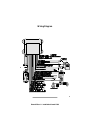
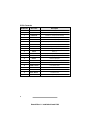
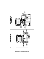
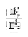
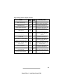
Phownix2 Rev. A - Installation Manual - Front Cover
Table of Contents
Important Information . . . . . . . . . . . . . . . . . . . . . . . . . . . 2
Required Installation Tools . . . . . . . . . . . . . . . . . . . . . . . . 2
Recommended Procedures . . . . . . . . . . . . . . . . . . . . . . . 2
Wiring Diagram . . . . . . . . . . . . . . . . . . . . . . . . . . . . . 3
20 Pin Connector . . . . . . . . . . . . . . . . . . . . . . . . . . . . 4
Installation Procedures. . . . . . . . . . . . . . . . . . . . . . . . . . . 5
Control Unit . . . . . . . . . . . . . . . . . . . . . . . . . . . . . . . 5
Antenna . . . . . . . . . . . . . . . . . . . . . . . . . . . . . . . . . 5
Wireloom . . . . . . . . . . . . . . . . . . . . . . . . . . . . . . . . 5
Zone2™ Impact Sensor. . . . . . . . . . . . . . . . . . . . . . . . . . 5
Valet Switch . . . . . . . . . . . . . . . . . . . . . . . . . . . . . . . 6
LED Indicator . . . . . . . . . . . . . . . . . . . . . . . . . . . . . . 6
Ignition Input . . . . . . . . . . . . . . . . . . . . . . . . . . . . . . 6
Channel 2 Accessory (-) Output . . . . . . . . . . . . . . . . . . . . . 6
Channel 4 Accessory (-) Output . . . . . . . . . . . . . . . . . . . . . 6
Channel 6 Accessory (-) Output . . . . . . . . . . . . . . . . . . . . . 7
Parking Lights . . . . . . . . . . . . . . . . . . . . . . . . . . . . . . 7
Interior Light Trigger/Illumination . . . . . . . . . . . . . . . . . . . . 7
Starter Disable . . . . . . . . . . . . . . . . . . . . . . . . . . . . . . 7
Door Lock/Unlock . . . . . . . . . . . . . . . . . . . . . . . . . . . . 8
Door Lock Diagrams . . . . . . . . . . . . . . . . . . . . . . . . . . 9
Hood/Trunk Pin Switch . . . . . . . . . . . . . . . . . . . . . . . . . 13
Siren . . . . . . . . . . . . . . . . . . . . . . . . . . . . . . . . . . 13
Power and Ground Connections . . . . . . . . . . . . . . . . . . . . 13
Programmable Features. . . . . . . . . . . . . . . . . . . . . . . . . . 14
Programming Table for Alarm Features . . . . . . . . . . . . . . . . . 15
Programming Table for Remote Controls . . . . . . . . . . . . . . . . 16
1
Phoenix2 Rev. A - Installation Manual 0399
Important Information
Required Installation Tools
Voltmeter
Wire Strippers
Electric Drill & Bits
Phillips Screw Driver
Convoluted Tubing *
Solder Gun *
Wire Crimpers
Shrink Tube or Electrical Tape
* Optional
Recommended Procedures
1. Test all circuits with a voltmeter.
2. Make all wiring connections with the supplied solderless crimp
connectors. DO NOT twist wires or use “scotch-lok” connectors.
3. Route RED, RED/WHITE and BLACK wires from the control unit directly
to the battery.
4. Keep extensions as short as possible. Use same gauge wires for short
extensions and larger gauge wires for longer extensions.
5. Before installing, discuss the placement of the LED indicator and valet
switch with the vehicle owner.
6. Make all battery connections by removing the bolts from the cable
clamps. DO NOT disconnect the battery cables.
7. Turn off dome light(s) or remove dome light fuse to prevent battery drain.
8. Making secure connections is a very important part of your installation.
Solderless crimp connectors are supplied in your hardware accessory
package. This type of connection is sufficient for most of your installation.
However, soldering of the starter disable wires is recommended whenever
possible. For a more secure installation, solder all of your connections and
insulate with heat shrink tubing.
This device complies with Part 15 of the FCC rules.
rules. Any
Any changes
changes or
or modifications
modifications
made to the system without the express approval of Prime Security could void the
user’s authority to operate this equipment.
2
Phoenix2 Rev. A - Installation Manual 0399
Wiring Diagram
3
Phoenix2 Rev. A - Installation Manual 0399
20 Pin Connector
Pin Number
Wire Color
Description
1
RED
Battery (+)
2
VIOLET
Siren (-) Output
3
DARK BLUE
Channel 2 (-) Output (Trunk Release)
4
LIGHT BLUE
Channel 4 (-) Output
5
BLUE / YELLOW
Channel 6 (-) Output
6
GRAY
Armed (-) Output Prewired to Starter Disable Relay
7
TAN
Hood / Trunk Switch (-) Input
8
PINK
Ignition Output
9
LIGHT GREEN
Second Stage Unlock (-) Output
10
BLACK
Battery (-)
11
RED / WHITE
Parking Light Polarity Input, (+) or (-) Input Select
12
RED / BLACK
Parking Light Output
13
WHITE
Interior Light Input
14
WHITE / BLACK
Door Trigger Polarity Select Input
15
GREEN / BLACK
Unlock Switch Side
16
GREEN / WHITE
Unlock Motor Side
17
GREEN / RED
Unlock Polarity (+) or (-) Input Select
18
BLUE / BLACK
Lock Switch Side
19
BLUE / WHITE
Lock Motor Side
20
BLUE / RED
Lock Polarity (+) or (-) Input Select
4
Phoenix2 Rev. A - Installation Manual 0399
Installation Procedures
Control Unit
1. Select a location under the dash that will allow you to use the tie wraps to
securely fasten the control unit.
2. Mount the control unit as high as possible to ensure maximum range.
3. Do not mount the control unit near moving parts.
4. Avoid areas that are in the direct path of air blowing from the vents.
5. Route wires from this point, leaving slack for ease of service.
Antenna
1. Do not shorten or lengthen the antenna.
2. Route the antenna away from the control unit.
3. Keep the antenna as far away from metal and wire harnesses as possible
to optimize range.
Wireloom
1. Plug the wireloom securely into the control unit.
2. Route wires from the control unit directly to each connection point.
3. Separate the RED, RED/WHITE, BLACK, VIOLET and TAN wires.
4. Sleeve the wires with vinyl tubing or electrical tape and route them
through an existing rubber grommet into the engine compartment.
5. If an existing grommet is not available, drill a hole and install a snap
grommet.
Zone2™ Impact Sensor
The sensor must be firmly mounted on a solid metal surface inside the vehicle.
We recommend tie wrapping the sensor to the steering column housing or
steering column support bracket. DO NOT mount the sensor near moving
parts or in the direct path of an air duct opening.
1. Plug the impact sensor BLUE 4-pin connector into the control unit BLUE
4-pin connector.
2. Route the impact sensor harness to the chosen mounting location.
3. Using the long tie wraps supplied, securely fasten the impact sensor
allowing access to the adjustment screws.
5
Phoenix2 Rev. A - Installation Manual 0399
Valet Switch
1. Discuss placement with the vehicle owner.
2. Choose a location for the valet switch that is hidden, but convenient for
the owner to access.
3. Drill a ¼" hole and mount the switch.
4. Route the valet switch wires to the control unit.
5. Plug the valet switch WHITE connector into the control unit WHITE plug.
LED Indicator
1. Discuss placement with the owner.
2. Choose a location that is visible from both sides of the vehicle.
3. Drill a ¼" hole.
4. Route the LED wires through the hole and press LED into place.
5. Route the LED wires to the control unit.
6. Plug the RED LED connector into the control unit RED plug.
Ignition Input
1. Use a voltmeter to locate the one wire that shows +12 volts when the
ignition key is in the "ON," "CRANK" and "RUN" positions, and 0 volts
when the ignition key is in the "OFF" position.
2. Connect the PINK wire to the vehicle ignition wire.
Channel 2 Accessory (-) Output
The DARK BLUE wire provides a 0.75 second ground (-) output when the
alarm is disarmed only. This is ideal for trunk release. If the remote control
button is continuously pressed, the signal will stay at ground as long as the
button is held.
NOTE: Most trunk releases are positive and require an optional relay.
Channel 4 Accessory (-) Output
The LIGHT BLUE wire provides a 0.75 second (-) output when activated
whether the alarm is armed or disarmed. If the remote control button is
continually pressed, the signal will stay at ground as long as the button is held.
6
Phoenix2 Rev. A - Installation Manual 0399
Channel 6 Accessory (-) Output (Arm/Disarm + Option Buttons)
The LIGHT BLUE/YELLOW wire provides a 0.75 second (-) output when
activated whether the alarm is armed or disarmed. If the remote control
button(s) is continually pressed, the signal will stay at ground as long as the
button is held.
Parking Lights
1. If the parking lights are positive trigger, connect the RED/WHITE wire to
the battery positive (+) terminal through the 20 amp fuse.
NOTE: Do not connect the RED/WHITE wire to the control unit
RED wire.
2. If the parking lights are negative (-) trigger, connect the RED/WHITE wire
to control unit BLACK wire.
3. Connect the RED/BLACK wire to the vehicle parking light wire.
Interior Light Trigger/Illumination
The system door trigger will accept a positive or negative door trigger input.
When the alarm is remotely disarmed, the interior lights will turn on for 30
seconds or until the ignition key is turned "ON." The WHITE/BLACK interior
light supply wire serves two purposes. It informs the alarm whether the door
trigger polarity is positive or negative switching and provides a positive or
negative supply for interior light illumination.
1. Connect the WHITE wire to the vehicle door trigger wire(s).
2. If the door trigger is negative switching, connect the WHITE/BLACK wire
to ground.
3. If the door trigger wire is positive switching, connect the WHITE/BLACK
wire to a constant fused +12 volt source.
Starter Disable
The alarm can be installed as Normally Open (N.O.) or Normally Closed
(N.C.) starter disable. It is factory set for Normally Closed.
NOTE: Make sure the YELLOW relay wires are solidly connected. The starter
circuit may draw very high current. We recommend that all starter wire
connections be soldered.
7
Phoenix2 Rev. A - Installation Manual 0399
Normally Closed
1. Locate the ignition switch wireloom under the dashboard.
2. Use a voltmeter to find the one wire that will show +12 volts while the
ignition key is in the cranking cycle only. This should be the starter
solenoid wire.
3. Cut the starter solenoid wire. Test by trying to crank the starter with the
ignition key. If it will not crank, you have the correct wire.
4. Connect one YELLOW wire to the key side.
5. Connect the other YELLOW wire to the starter side.
Normally Open
1. Unplug the YELLOW wire from relay terminal 87A and insert the
YELLOW wire into relay terminal 87.
2. Locate the ignition switch wireloom under the dashboard.
3. Use a voltmeter to find the one wire that will show +12 volts while the
ignition key is in the cranking cycle only. This should be the starter
solenoid wire.
4. Cut the starter solenoid wire. Test by trying to crank the starter with the
ignition key. If it will not crank, you have the correct wire.
5. Connect one YELLOW wire to the key side.
6. Connect the other YELLOW wire to the starter side.
7. Program the alarm module for Normally Open (N.O.) starter disable (see
"Programming Table for Alarm Features").
Door Lock/Unlock
The alarm has on-board relays to lock and unlock the doors. It also has a
second unlock (-) output wire (GREEN) that will allow you to do Two-Stage
Unlock. The second stage unlock wire provides a 400 ma, 0.75 second (-)
output when activated.
Two-Stage Unlock
Be sure to verify the type of door lock system you are
working with. Carefully follow the door lock/unlock diagrams on
I CAUTION:
pages 9-12.
1. Press the remote arm/disarm button once and the driver door only will
unlock.
2. Press the remote arm/disarm button again within 3 seconds and the
passenger doors will unlock.
8
Phoenix2 Rev. A - Installation Manual 0399
9
Phoenix2 Rev. A - Installation Manual 0399
10
Phoenix2 Rev. A - Installation Manual 0399
11
Phoenix2 Rev. A - Installation Manual 0399
12
Phoenix2 Rev. A - Installation Manual 0399
Hood/Trunk Pin Switch
1. Locate the vehicle hood or trunk pin switch that shows ground when the
hood or trunk is open only.
2. Connect the TAN wire to the vehicle hood or trunk switch wire.
3. If the vehicle does not have a hood or trunk switch, install a pin switch
and connect it to the TAN wire.
Siren
1. Choose a location in the engine compartment away from high heat engine
components, moving parts and direct exposure to water.
2. Make sure the siren and siren wires cannot be seen or reached from
below the vehicle.
3. Mount the siren with the two self tapping screws to a solid metal surface.
4. Connect the siren BLACK wire to the alarm module VIOLET wire.
5. Connect the siren RED wire to the alarm module RED wire.
Power and Ground Connections
Do not plug in the system fuses until the final step
below.
I CAUTION:
1. Connect the RED wire to one of the supplied fuse assemblies.
2. Connect the RED/WHITE wire to the other fuse assembly (if the vehicle
parking lights are (+) positive).
3. Connect the fuse assembly(s) to one of the supplied 10mm ring terminals.
4. Connect the BLACK wire to the other 10mm ring terminal.
5. Remove the (+) and (-) battery bolts. Do not disconnect the battery
clamps.
6. Connect the empty fuse assembly(s) to the positive battery post.
7. Connect the BLACK wire to the battery negative post.
8. Inspect all alarm wiring. Make sure all wires are connected.
9. Install the 5 amp fuse in the RED wire fuse assembly.
10. Install the 20 amp fuse in the RED/WHITE fuse assembly (if the vehicle
parking lights are positive).
13
Phoenix2 Rev. A - Installation Manual 0399
Programmable Features
All system and remote control programmable features are accomplished by
turning the ignition key to the "ON" position or starting the engine and flicking
the valet switch on and off a preset number of times. The siren will chirp for
audible programming confirmation.
The system also allows you to add new remote controls in one step, delete lost
or stolen remote controls or rearrange the factory preset remote control
functions.
1. Remove the system from Protected or Remote-Controlled Valet Mode.
Programming cannot be accessed while the system is in Valet Mode
indicated by the LED on solid red.
2. Select the feature you wish to program from the "Programming Table for
System Features" or the "Programming Table for Remote Controls" on
pages 15-16. Note the number of chirps associated with that feature.
3. Turn the ignition key to the "ON" position.
4. Within 10 seconds, begin flicking the valet switch on and off. The siren
will chirp once each time you flick the switch on then off.
5. Continue flicking the switch on and off, counting the number of chirps.
NOTE: Stop when you reach the number of chirps associated with your
chosen feature.
6. Follow the "Secondary Action." You will hear a number of chirps to
confirm that you have changed the setting of that feature.
7. Turn the ignition key "OFF."
8. Repeat steps 1-7 for any other feature you wish to program.
14
Phoenix2 Rev. A - Installation Manual 0399
Programming Table for System Features
Feature
Factory
Setting
No. of
Chirps
Secondary Action
Active / Passive Arming
Passive
4
Wait 3 seconds, the siren will chirp
once for active, twice passive.
Passive Door Lock
OFF
5
Wait 3 seconds, the siren will chirp
once for Off, twice for On.
Passive Armed Confirmation
ON
6
Wait 3 seconds, the siren will chirp
once for Off, twice for On.
2 Pulse Unlock
1 Pulse
7
Wait 3 seconds, the siren will chirp
once for 2 pulse, twice for 1.
1 Second
8
Wait 3 seconds, the siren will chirp
once for 3 seconds, twice for
1 second.
Ignition-Controlled Door
Lock/Unlock
ON
9
Wait 3 seconds, the siren will chirp
once for Off, twice for On.
Programmable 0 or 3 Second Delay
for Ignition-Controlled Door Lock
0
Seconds
10
Wait 3 seconds, the siren will chirp
once for 3 seconds, twice for
0 seconds.
Normally Open / Normally Closed
Starter Disable
Normally
Closed
11
Wait 3 seconds, the siren will chirp
once for normally open, twice for
normally closed.
Door Ajar Indication
ON
12
Wait 3 seconds, the siren will chirp
once for Off, twice for On.
Siren Duration
30 or 60 seconds
30
Seconds
13
Wait 3 seconds, the siren will chirp
once for 60 seconds, twice for 30.
Long-Term Silent Arm/Disarm
ON
14
Wait 3 seconds, the siren will chirp
once for Off, twice for On.
Door Lock/Unlock Output Duration
(1 or 3 Seconds)
15
Phoenix2 Rev. A - Installation Manual 0399
Programming Table for Remote Controls
Feature
Factory Setting
No. of
Chirps
Secondary Action
Arm/Disarm
ARM/DISARM
Button
15
Press the ARM/DISARM button, the
siren will chirp 1 time.
Remote-Controlled
Trunk Release Output
TRUNK Button
16
Press the TRUNK button, the siren
will chirp 2 times.
Remote-Controlled
Silent Arm/Disarm
SILENT Button
17
Press the SILENT button, the siren will
chirp 3 times.
Channel 4
Remote-Controlled
Accessory Output
OPTION Button
18
Press the OPTION button, the siren
will chirp 4 times.
Remote-Controlled Valet
ARM/DISARM +
SILENT Buttsons
19
Press the ARM/DISARM + SILENT
buttons, the siren will chirp 5 times.
Channel 6
Remote-Controlled
Accessory Output
ARM/DISARM +
OPTION Buttons
20
Press the ARM/DISARM + OPTION
buttons, the siren will chirp 6 times.
Remote-Controlled
Sensor Bypass
TRUNK +
OPTION Buttons
21
Press the TRUNK + OPTION buttons,
the siren will chirp 7 times.
One Step Remote
Control Code Learning
ARM/DISARM
Button
22
Press ARM/DISARM button, the siren
will chirp 1 time.
Instant Remote Control
Code Deletion
—
23
Wait 3 seconds, the siren will chirp
twice, all codes are erased out of
memory.
16
Phoenix2 Rev. A - Installation Manual 0399
Phoenix2 Rev. A - Installation Manual 0399
© 1999 Avital Technologies, Inc.
Part Number: 32-1270 Rev. A
Phoenix2 Rev. A - Installation Manual 0399
Phoenix2 Rev. A - Installation Manual 0399