1
Command Reference
MOBILE LINE THERMAL PRINTER
MODEL CMP-10
Rev. 3.10 Revised on Dec 13, 2006
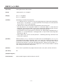
REVISION
Rev. No.
Rev. 1.00
Date
2002/11/15
Newly issued
Comment
Rev. 1.01
2002/12/18
Revised P. 1, P. 2, P. 47, P. 54, P. 56, P. 59
Rev. 1.02
2003/01/17
Added Chapter 3 (Character Codes Table) and Chapter 4
Rev. 2.00
2003/06/30
Added ESC >, ESC l, FF (Firmware Ver. 1.95)
Revised GS )
Added Chapter 5 to Chapter 10
Rev. 3.00
2006/07/13
Added baud rate 38400 at page of ESC S n and 5.1 (2)
Added GS z
Rev. 3.01
2006/08/31
Revised range of CODE128 on Page56
Rev. 3.10
2006/12/13
Added new Chapter 4. Deleted [Remarks] on page 63.
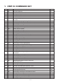
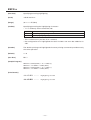
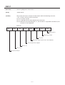
1. CMP-10 COMMAND SET
1
2
3
4
5
6
7
8
9
10
11
12
13
14
15
16
17
18
19
20
21
22
23
24
25
26
27
28
29
30
31
32
33
34
35
36
37
38
39
40
41
42
43
Code
BEL
HT
LF
CR
ESC RS
ESC SP
ESC !
ESC $
ESC %
ESC &
ESC *
ESC +
ESC –
ESC .
ESC 2
ESC 3
ESC =
ESC >
ESC ?
ESC @
ESC D
ESC E
ESC G
ESC J
ESC R
ESC S
ESC T
ESC V
ESC Y
ESC Z
ESC \
ESC _
ESC `
ESC a
ESC c5
ESC d
ESC v
ESC x
ESC {
GS )
GS *
GS /
GS :
Command Function
Sounds the Buzzer
Horizontal Tab Command
Printing and Paper Feed Command
Print one line Command
Sounds the Buzzer
Setting the right space amount of the
character
Collective Specifying Printing Mode
Specifying the Absolute Positions
Specifying/Canceling Download Character Set
Define user characters
Specifying the Bit Image Mode
Switch OFF the printer
Specifying/ Canceling Underline
Printer self test
Specifying 1/6-inch line feed rate
Setting line feed rate of minimum pitch
Data Input Control
Saving current setting
Reading magnetic stripe reader
Initializing the Printer
Setting Horizontal Tab Position
Specifying/canceling highlighting
Specifying/canceling Double Printing
Printing and feeding paper n/203 inch
Selecting Code table
Setting serial interface communication speed
Printing Diagnostic information
Specifying/Canceling 90°-right- turned
Characters
Specifying print density
Returning diagnostic information
Specifying the relative positions
Setting the printer in default state
Returning the battery voltage and Printer
Head temperature
Aligning the characters
Enabling/Disabling Panel Switches
Printing and Feeding the paper by n lines
Transmitting the printer status
Selecting the time interval for automatically
switching Off the printer
Specifying/Canceling the Inverted Characters
Setting of printer flags
Defining the Download Bit Image (LOGO)
Printing the Download, Bit Image
Starting/Ending Macro Definition
—1—
Page
4
5
6
7
7
8
9
11
12
13
14
17
17
18
18
19
20
21
22
23
24
25
26
27
27
28
28
29
30
31
34
34
*
*
*
*
*
*
*
*
*
*
*
*
*
35
36
37
38
39
*
40
41
42
43
44
45
*
*
44
45
46
47
48
49
50
51
52
53
54
55
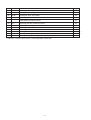
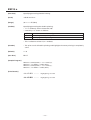
Code
GS H
GS L
GS W
GS ^
GS a
GS f
GS h
GS k
GS w
GS z
ESC l
FF
Command Function
Selecting of Printing Position of HRI Code
Setting the left margin
Setting the print area width
Executing the Macro
Enabling/Disabling
ASB (Automatic Status Back)
Selecting the font of HRI characters
Selecting the height of the Bar Code
Printing the bar code
Selecting the horizontal size (Scale factor) of the Bar Code
Saving AT command sequences to send to Bluetooth module
Specify/canceling black mark function
Printing and paper feeding to the black mark position
* indicates a unique command or a non-compatible command.
—2—
Page
46
47
48
50
51
54
55
56
61
62
64
64
*
*
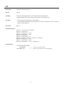
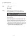
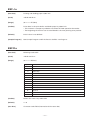
2. COMMAND DETAILS
2.1 Description of Items
XXXX
ALL
[Function]
Command Function
[Code]
A sequence of code constituting a command is represented in hexadecimal number
for < >H, binary number for < >B, and decimal number for < >, respectively; [ ]k
represents a repeat count of k-times.
[Range]
Indicates an argument value (setting range) for the command in hexadecimal number
(partly in decimal number).
* When used for application other than defined in each control, an error may occur.
Always use in the defined range.
[Outline]
Describes a command outline.
[Caution]
Describes a caution as required.
[Default]
Describes an initial value in hexadecimal number for the command when accompanied
by an argument.
[See Also]
Describes the associated commands for use.
[Sample Program]
Describes a coding example in the Q-BASIC sample program.
* This example is only for your reference and differs depending on the language
used, version, and so on. For details, see the manual for the language used.
—3—
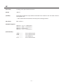
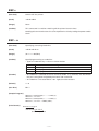
BEL
[Function]
Sounds the Buzzer
[Code]
<07>H
[Outline]
By executing this command the buzzer will beep.
This command functions in the same manner as ESC RS.
—4—
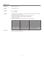
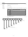
HT
[Function]
Horizontal Tab Command
[Code]
<09>H
[Outline]
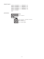
Shifts the printing position to the next horizontal tab position.
• Ignored when the next horizontal tab position has not been set.
[Caution]
• The horizontal tab position is set by ESC D.
• Initial setting of the horizontal tab position is each 8 characters in 9th, 17th, 25th,
columns from FONT A.
[See Also]
ESC D
[Sample Program]
PRINT #1, “0123456789012345678901”;
PRINT #1, CHR$ (&HA);
PRINT #1, CHR$ (&H9) + “AAA”;
PRINT #1, CHR$ (&H9) + “BBB”;
PRINT #1, CHR$ (&HA);
PRINT #1, CHR$ (&H1B) + “D”;
PRINT #1, CHR$ (3) + CHR$ (7) + CHR$ (14) + CHR$ (0);
PRINT #1, CHR$ (&H9) + “AAA”;
PRINT #1, CHR$ (&H9) + “BBB”;
PRINT #1, CHR$ (&H9) + “CCC” + CHR$ (&HA);
[Print Results]
123456789012345678901
←
AAA BBB
←
AAA BBB CCC
—5—
Initially set horizontal tab
When set to the 4th, 8th, and 15th digits
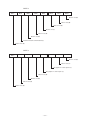
LF
[Function]
Printing and Paper Feed Command
[Code]
<0A>H
[Outline]
Prints data inside the input buffer and feeds lines based on the line feed amount
having been set.
• The head of the line becomes the next print starting position.
[See Also]
ESC 2, ESC 3
[Sample Program]
PRINT #1, “AAA” + CHR$ (&HA);
PRINT #1, “BBB” + CHR$ (&HA);
PRINT #1, CHR$ (&HA);
PRINT #1, “CCC” + CHR$ (&HA);
[Print Results]
AAA ←
BBB ←
←
CCC ←
Print and line feed
Print and line feed
Line feed only
Print and line feed
—6—
CR
[Function]
Print one line Command
[Code ]
<0D>H
[Outline]
This command is ignored or its action is the same as LF depending on the last
execution of GS ) 2 command (FLAG SETTING COMMAND).
If Flag 2 is 0, carriage return (CR) command is ignored.
If Flag 2 is 1, CR comamnd will act as LF command.
[Default]
CR command is ignored. If you want that it acts like LF command set flag 2 to 1 by
GS ) command.
[See Also]
GS )
ESC RS
[Function]
Sounds the Buzzer
[Code]
<1B>H<1E>H
[Outline]
By executing this command the buzzer will beep.
This command functions in the same manner as BEL.
—7—
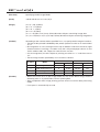
ESC SP n
[Function]
Setting the right space amount of the character
[Code]
<1B>H<20>H<n>
[Range]
{0 =< n =< 20(Hex)}
[Outline]
The rightward space amount is set in dot unit (1/203 inch unit).
[Caution]
The rightward space amount in doublewide mode is made double of the set volume.
[Default]
n=0
[Sample Program]
PRINT #1, CHR$ (&H1B) + “ “ + CHR$ (0);
PRINT #1, “AAAAA” + CHR$ (&HA);
PRINT #1, CHR$ (&H1B) + “ “ + CHR$ (1);
PRINT #1, “AAAAA” + CHR$ (&HA);
PRINT #1, CHR$ (&H1B) + “ “ + CHR$ (12);
PRINT #1, “AAAAA” + CHR$ (&HA);
[Print Results]
AAAAA
AAAAA
A A A A A
←
←
←
0-dot space
1-dot space
12-dot space
—8—
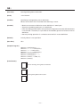
ESC ! n
[Function]
Collective Specifying Printing Mode
[Code]
<1B>H<21>H<n>
[Range]
{0 =< n =< FF(Hex)}
[Outline]
Printing mode is assigned.
Bit
0
1
2
3
4
5
6
7
[Caution]
Function
Character Font
Undefined
Undefined
High-lighting
Double height
Double width
Undefined
Underline
Value
0
Font A
1
Font B
Canceled
Canceled
Canceled
Specified
Specified
Specified
Canceled
Specified
Each n bit indicates the following:
• With double height and double width being specified simultaneously, double wide
and double high characters are consisted.
• An underline is attached to the full character width, which, however, is not attached
to the part having been skipped by the horizontal tab.
Neither is it attached to 90°-right-turned characters.
• The underline width is as having been specified by <ESC ->. (The default setting is
1 dot width.)
• n case that double wide character and normal character exist in same one line, the
layout of underline is consistent one.
[Default]
n=0
[See Also]
ESC E, ESC –
—9—
[Sample Program]
PRINT #1, CHR$(&H1B) + “!” + CHR$(&H00) + “H” ;
PRINT #1, CHR$(&H1B) + “!” + CHR$(&H01) + “H” ;
PRINT #1, CHR$(&H1B) + “!” + CHR$(&H08) + “H” ;
PRINT #1, CHR$(&H1B) + “!” + CHR$(&H10) + “H” ;
PRINT #1, CHR$(&H1B) + “!” + CHR$(&H20) + “H” ;
PRINT #1, CHR$(&H1B) + “!” + CHR$(&HB9) + “H” ;
PRINT #1, CHR$(&HA) ;
END
[Print Results]
Font A
Font B
Font A + Emphasis
>
>
>
>
>
>
>
Font B + Emphasis + Quadruple + Underline
Font + Underline
Font A + Double Width
Font A + Double Height
— 10 —
ESC $ n1 n2
[Function]
Specifying the Absolute Positions
[Code]
<1B>H<24>H<n1><n2>
[Range]
{0 =< n1 =< FF(Hex)}
{0 =< n2 =< 1(Hex)}
[Outline]
The printing start position is specified in the number of dots (1/203 inch unit) from
the beginning of line.
• The number of dots is divided by 256, whose quotient is taken as n2 and the residual
as n1.
• Therefore, the printing start position is equal to n1 + n2 × 256 from the beginning of
line.
[Caution]
Specifying beyond the line end is ignored.
[Default]
The initial value is not specified.
[See Also]
ESC \
[Sample Program]
PRINT #1, CHR$ (&H1B) + “$”;
PRINT #1, CHR$ (0) + CHR$ (0) + “A”;
PRINT #1, CHR$ (&H1B) + “$”;
PRINT #1, CHR$ (50) + CHR$ (0) + “B”;
PRINT #1, CHR$ (&H1B) + “$”;
PRINT #1, CHR$ (0) + CHR$ (1) + “C”;
PRINT #1, CHR$ (&HA);
PRINT #1, CHR$ (&H1B) + “$”;
PRINT #1, CHR$ (100) + CHR$ (0) + “A”;
PRINT #1, CHR$ (&H1B) + “\”;
PRINT #1, CHR$ (&HC2) + CHR$ (&HFF) + “B”;
PRINT #1, CHR$ (&HA);
[Print Results]
50
>
>
B
B
>
>
A
100
256
>
0
C
A
>
— 11 —
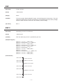
ESC % n
[Function]
Specifying/Canceling Download Character Set
[Code]
<1B>H<25>H<n>
[Range]
{0 =< n =< FF(Hex)}
[Outline]
Specifying/canceling download characters.
Further, only the lowest bit (n0) is valid for n.
n (Hex)
0
1
Function
Selecting download character set
Canceling download character set
[Caution]
This setting cannot be restored to initial value even with Initialize command or by
turning power OFF. It can be restored to the initial value by ESC _, a command for
returning to initial state.
[Default]
n=0
[See Also]
ESC &
— 12 —
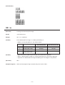
ESC & m n1 n2 [d] k
[Function]
Define user characters
[Code]
<1B>H<26>H<m><n1><n2>[<d>]k
[Range]
{m = 0, 1, 2, 3(Hex)}
{20 =< n1 =< FF(Hex)}
{n1 =< n2 =< FF(Hex)}
{k=(n2-n1+1)*48} (m=2)
{k=(n2-n1+1)*16} (m=3)
[Outline]
Defines a group of user characters.
m=0: Copy internal character set A to user character set A
(Parameters n1, n2 and d are omitted)
m=1: Copy internal character set B to user character set B
(Parameters n1, n2 and d are omitted)
m=2: For Font A (12 × 24), n1 denotes Start character code and n2 End character
code. Every character is 48 bytes, two bytes for each line. Only the first nibble
of the second byte is used.
m=3: Define character group with ASCII codes between >= n1 and =< n2 for character
set B (9 × 16). Every character is 16 bytes.
[Caution]
The data for character set A is composed from left to right and from top to bottom
with two bytes for each horizontal line. The first byte contains the first 8 bits with
the left most bit is MSB. From the second byte only the first nibble (the most significant
4 bits) is valid.
The data for character set B is composed from left to right and from top to bottom
with only one byte for each horizontal line. The nineth bith is alawys 0.
Downloaded characters are valid even after switching off the printer or after issuing
Initialize command.
Download character
Font A (12 × 24)
(Last 4 bits are not used and fixed as zero.)
d1
d3
d5
d7
d9
Font B (9 × 16)
(9th dot is fixed as space.)
d2
d4
d6
d8
d10
d1
d2
d3
d4
d5
16
24
d14
d15
d16
8 7 6 5 4 3 2 1
d44
d46
d48
d43
d45
d47
MSB
0 0 0 0 LSB
8 7 6 5 4 3 2 1
— 13 —
ESC * m n1 n2 [d] k
[Function]
Specifying the Bit Image Mode
[Code]
<1B>H<2A>H<m><n1><n2> [d] k
[Range]
{m= 0, 1, 20, 21(Hex)}
{0 =< n1 =< FF(Hex)}
{0 =< n2 =< 1(Hex)}
{0 =< d =< FF(Hex)}
{k = n1 + FF(Hex) x n2} (m=0, 1(Hex)) Number of bytes containing image data
{k = (n1 + FF(Hex) x n2) x 3} (m=20, 21(Hex)) Number of bytes containing image data
[Outline]
According to the number of dots specified in n1, n2, specify the bit image of mode m.
• The No. of dots printed is divided by 256, whose quotient is taken as n2 and residual
as n1.
• Bit image data is sent starting from the top to bootom and from the left to right
(vertical columns scanning). In modes m=0, and 1 only one byteper column is sent
and in mode m-20h, 21h 3 bytes for each column are sent.
• d is bit image data, the bits subject to printing are taken as “1” and those not as
“0”.
• The bit image modes specified by m are shown as follows:
[Caution]
m (Hex)
Mode
0
1
20
21
8-dot single density
8-dot double density
24-dot single density
24-dot double density
Vertical Direction
Horizontal Direction
Dots
Dot Density Dot Density Max. Dots
8
67 DPI
101 DPI
192
8
67 DPI
203 DPI
384
24
203 DPI
101 DPI
192
24
203 DPI
203 DPI
384
• When the values set in m (bit image mode) are out of the above range, the data
following after n1 is processed as normal printing data.
• After completion of bit image printing, printer returns to normal data processing
mode.
• Line space is automatically set to 0.
— 14 —
[Sample Program]
PRINT #1, CHR$(&H1B) + “ * ”;
PRINT #1, CHR$(0) + CHR$(20) + CHR$(0);
GOSUB IMG1
PRINT #1, CHR$(&HA);
PRINT #1, CHR$(&H1B + “ * ”;
PRINT #1, CHR$(1) + CHR$(20) + CHR$(0);
GOSUB IMG1
PRINT #1, CHR$(&HA);
PRINT #1, CHR$(&H1B) + “ * ”;
PRINT #1, CHR$(32) + CHR$(20) + CHR$(0);
GOSUB IMG2
PRINT #1, CHR$(&HA);
PRINT #1, CHR$(&H1B) + “ * ”;
PRINT #1, CHR$(33) + CHR$(20) + CHR$(0);
GOSUB IMG2
PRINT #1, CHR$(&HA);
END
[Print Results]
←
8-dot single density
←
8-dot double density
←
24-dot single density
←
24-dot double density
— 15 —
IMG1:
PRINT #1, CHR$(&HFF);
FOR I=1 TO 18
PRINT #1, CHR$(&H85);
NEXT I
PRINT #1, CHR$(&HFF);
RETURN
IMG2:
PRINT #1, CHR$(&HFF);
PRINT #1, CHR$(&HFF);
PRINT #1, CHR$(&HFF);
FOR I=1 TO 18
PRINT #1, CHR$(&H80);
PRINT #1, CHR$(&H00);
PRINT #1, CHR$(&H05);
NEXT I
PRINT #1, CHR$(&HFF);
PRINT #1, CHR$(&HFF);
PRINT #1, CHR$(&HFF);
RETURN
This command has one more version.
[Function]
Specifying the Bit Image Mode (PCX format)
[Code]
<1B>H<2A>H<m><n>{<a><00>H} [d]k
[Range]
{m= 10, 11 or 12(Hex)}
{0 =< n =< 30(Hex)}
{0 =< a =< 18(Hex)}
{0 =< d =< FF(Hex)}
{0 =< k =< n x 18(Hex)}
[Outline]
Designates a bit image of n*8 dots horizontal by 24 or a dots vertical.
Dot density is fixed at 203 dpi both horizontally and vertically.
Bit image mode selected by the value of m is shown in the following table.
m (Hex)
10
11
12
Type
Non-compressed data of 24 dots vertical
(Argument “a” and 00(Hex) are not used.)
Compressed data of 24 dots vertical
(Argument “a” and 00(Hex) are not used.)
Compressed data of a dots vertical
n denotes the number of bytes for horizontal size of a bit image.
d denotes a graphic data.
In 10(Hex) mode, data is in n × 24 bytes.
For data in 11(Hex) mode, the size in non-compressed format shall be n × 24 bytes.
For data in 12(Hex) mode, the size in non-compressed format shall be n × a bytes.
Compression system in 11(Hex) and 12(Hex) is the same as that for PCX file format
(monochrome). The printer receives the compressed data, reproduces it in the
following format and prints as bit-image data.
A If either of upper two bit of input byte is 0, the byte is treated as graphic data.
If both of upper two bit of graphic data to be printed are 0, it is necessary to send
the data to printer in “B” format described below.
B If both of upper two bit of input byte are 0, the remaining 6 bit specifies the times
the data is repeated. The number of times to be repeated is specified in 0-3F(Hex).
The byte follows this byte is treated as graphic data to be repeated.
Graphics data should line up from left to right and from top to bottom.
— 16 —
ESC +
[Function]
Switch OFF the printer
[Code]
<1B>H<2B>H
[Range]
None
[Outline]
This command is used for switching off the printer from the host.
Sending this command causes the same operation as that by setting the power switch
to off.
ESC – n
[Function]
Specifying/ Canceling Underline
[Code]
<1B>H<2D>H<n>
[Range]
{0 =< n =< 02(Hex)}
[Outline]
Specifying/canceling an underline.
• Types of underlines by n value are shown below:
n (Hex)
0
1
2
Type
Canceling an underline.
Specifying an underline for 1-dot width.
Specifying an underline for 2-dots width.
[Caution]
• An underline is attached to the full character width. It is, however, not attached to
the part having been skipped by horizontal tab command.
• An underline is not attached to a 90°- right-turned characters.
[Default]
n=0
[See Also]
ESC !
[Sample Program]
PRINT #1, CHR$ (&H1B) + “–” + CHR$ (0);
PRINT #1, “AAAAA” ;
PRINT #1, CHR$ (&H1B) + “–” + CHR$ (1);
PRINT #1, “AAAAA” + CHR$ (&HA);
[Print Results]
Underline Canceled
>
>
AAAAAAAAAA
>
Underline Specified
>
— 17 —
ESC .
[Function]
Printer self test
[Code]
<1B>H<2E>H
[Range]
None
[Outline]
Prints test page, downloaded bit image, and self-diagnostic information. The selfdiagnostic information includes print density, print head temperature, battery voltage,
Serial or IrDA interface, baud rate, and memory switch setting.
[See Also]
ESC T
ESC 2
[Function]
Specifying 1/6-inch line feed rate
[Code]
<1B>H<32>H
[Outline]
The line feed rate per line is specified by 1/6 inch.
[Sample Program]
PRINT #1, “AAAAA” + CHR$ (&HA);
PRINT #1, CHR$ (&H1B) + “3” + CHR$ (0);
PRINT #1, “AAAAA” + CHR$ (&HA);
PRINT #1, CHR$ (&H1B) + “3” + CHR$ (50);
PRINT #1, “AAAAA” + CHR$ (&HA);
PRINT #1, CHR$ (&H1B) + “2”;
PRINT #1, “AAAAA” + CHR$ (&HA);
PRINT #1, “AAAAA”;
PRINT #1, CHR$ (&H1B) + “J” + CHR$ (100);
PRINT #1, “AAAAA” + CHR$ (&HA);
PRINT #1, “AAAAA” + CHR$ (&HA);
> >
AAAAA
AAAAA
1/6-inch line feed
> >
AAAAA
>
[Print Results]
0/203-inch line feed
50/203-inch line feed
>
>
AAAAA
1/6-inch line feed
>
>
AAAAA
100/203-inch line feed
>
>
AAAAA
1/6-inch line feed
>
AAAAA
— 18 —
ESC 3 n
[Function]
Setting line feed rate of minimum pitch
[Code]
<1B>H<33>H<n>
[Range]
{0 =< n =< FF(Hex)}
[Outline]
The line feed rate per line is specified by n/203 inch.
[Default]
n = 22(Hex) 1/6-inch
[Sample Program]
See Sample Program and Print Results for ESC 2.
— 19 —
ESC = n
[Function]
Data Input Control
[Code]
<1B>H<3D>H<n>
[Range]
{0 =< n =< FF(Hex)}
[Outline]
Selecting equipment in which data input from the host is effective.
• Each bit of n indicates as follows:
Bit
Equipment
0
1
2
3
4
5
6
7
Printer
Not defined
Not defined
Not defined
Not defined
Not defined
Not defined
Not defined
Value
0
Invalid
1
Valid
• When the printer has not been selected, this printer abandons all the received data
until it is selected by this command.
[Caution]
• Even when the printer has not been selected, it can become BUSY state through
printer operation.
• When the printer is deselected, this printer discards all the data until it is selected
with this command.
[Default]
The initial value of n is “1”.
[Sample Program]
PRINT #1, “AAAAA”;
PRINT #1, CHR$ (&H1B) + “=” + CHR$ (0);
PRINT #1, “aaaaa” + CHR$ (&HA);
PRINT #1, CHR$ (&H1B) + “=” + CHR$ (1);
PRINT #1, “AAAAA” + CHR$ (&HA);
[Print Results]
>
AAAAAAAAAA
a a a a a
— 20 —
ESC > n
[Function]
Saving current setting
[Code]
<1B>H<3E>H<n>
[Range]
n = 0 or 1
[Outline]
This command saves International character, Serial port baud rate, Print density, Auto
power off time and maximum speed at Infrared communication to NV memory so
that the setting can be resumed automatically when power on after setting data on
RAM memory is gone by like battery is disconnected.
n (Hex)
0
1
Type
Max speed at Infrared communication is 115200 bps.
Max speed at Infrared communication is 57600 bps.
[Caution]
Do NOT use this command frequently.
NEVER turn the printer off during command is running. Otherwise there is a risk to
lose the firmware updating function.
Power is turned off automatically when setting is saved.
[Default]
n=0
[See Also]
ESC R, ESC S, ESC Y, ESC x
— 21 —
ESC ? n
[Function]
Reading magnetic stripe reader
[Code]
<1B>H<3F>H<n>
[Range]
{0 =< n =< 7(Hex)}
[Outline]
When the command is received the bicolor LED is shining in RED and the printer is
waiting for the magnetic card to be swiped through the reader. If even after 10
seconds the card is not swiped the command is aborted automatically.
Printer returns the information read from the tracks followed by 00(Hex).
Reads the data of the track in the following table by the value of n.
n (Hex)
0
1
2
3
4
5
6
7
Track
Invalid
Track 1
Track 2
Track 1 and 2
Track 3
Invalid
Track 2 and 3
Invalid
The format of the data read is as follows.
Track
Header
Card data
Footer
Track
Track 1 is F1 (Hex)
Track 2 is F2 (Hex)
Track 3 is F3 (Hex)
Header
Track 1: “%”
Track 2: “;”
Track 3: “+” or “;”
Card data
ASCII data
Footer
“?”
If reading track is more than one (n=3 or 6), footer data of track 1 or 2 is followed by
track data of track 2 or 3.
[Caution]
The command for reading multiple tracks at a time may often result in read error.
If reading is unsuccessful, repeat it.
— 22 —
ESC @
[Function]
Initializing the Printer
[Code]
<1B>H<40>H
[Outline]
Clears data stored in the print buffer and brings various settings to the initial state
(Default state). Items not cleared are as shown below.
• Data inside the internal input buffer are not cleared.
• Does not clear any data in the internal input buffer.
• Does not clear downloaded characters.
• Does not clear defined downloaded characters.
• Does not clear defined downloaded bit image.
• Does not clear defined macro.
• Does not clear setting for print density.
• Does not clear baud rate setting of serial port.
• Does not clear valid/invalid setting for panel switch.
• Does not clear ASB mode setting.
• Does not clear setting for auto power-off time.
• Does not clear memory switch.
[Caution]
At power off, the following settings are cleared in addition to the items cleared by
this command.
• Clears input buffer.
• Clears macro.
• Return ASB mode according to the memory switch setting.
• Clears valid/invalid setting for panel switch.
[Sample Program]
PRINT #1, CHR$ (&H1B) + “ ! “ + CHR$ (&H30) ;
PRINT #1, CHR$ (&H1B) + “V” + CHR$ (1);
PRINT #1, “AAA” + CHR$ (&HA);
PRINT #1, CHR$ (&H1B) + “@”;
PRINT #1, “AAA” + CHR$ (&HA);
[Print Results]
A
A
A
AAA
— 23 —
ESC D [ n ] k NUL
[Function]
Setting Horizontal Tab Position
[Code]
<1B>H<44>H [ <n> ] k<00>H
[Range]
{0 =< n =< FF(Hex)}
{0 =< k =< 20(Hex)}
[Outline]
Specifying a horizontal tab position.
• “n” indicates the no. of columns from the beginning to the horizontal tab position.
At this time, n= set position – 1 is to be specified. For example, to set the position
at 9th column, n=8 is to be specified.
• k denotes the number of horizontal tab positions you want to set.
• The tab position is set at position where it is “character width × n” from the line
beginning. The character width, at this time, includes the rightward space amount.
In double wide characters, it is made double of the ordinary case.
• Tab positions can be specified are maximum 32. Specifying exceeding this is
ignored. <n> k, which denotes a setting position, is input in the increasing order
and ends at <00> H.
• ESC D NUL clears all the set tab positions. Following clearing, horizontal tab
command is ignored.
[Caution]
When the data, <n> k, is equal to or smaller than its preceding data, <n> k-1, it is
assumed that tab setting is finished. If this is the case, the next data onward will be
processed as normal data. When the data, <n> k, exceeds a 1-line print area, set the
horizontal tab position, assuming “Set digit position = Maximum print digits + 1.”
The horizontal tab position does not change even if the character width is altered
after setting the horizontal tab position.
[Default]
Initial value is specified every eight characters (9th, 17th, 25th, and on) of Font A.
[See Also]
HT
[Sample Program]
[Print Results]
See Sample Program and Print Results for HT.
— 24 —
ESC E n
[Function]
Specifying/canceling highlighting
[Code]
<1B>H<45>H<n>
[Range]
{0 =< n =< FF(Hex)}
[Outline]
Specifying/canceling the highlighting characters.
• “n” is valid only for the lowest bit (n0).
n (Hex)
0
1
Type
Canceling highlighting.
Specifying highlighting.
• This is effective only for font A (12 × 24 dots)
• Dot configuration of a highlighted character includes one extra dot added at its
side.
[Caution]
The double printing and highlighted character printing commands provide exactly
the same operation.
[Default]
n=0
[See Also]
ESC !
[Sample Program]
PRINT #1, CHR$ (&H1B) + “E” + CHR$ (0);
PRINT #1, “AAABBB” + CHR$ (&HA);
PRINT #1, CHR$ (&H1B) + “E” + CHR$ (1);
PRINT #1, “AAABBB” + CHR$ (&HA);
[Print Results]
AAA B B B
←
Highlighting canceled
AAA B B B
←
Highlighting canceled
— 25 —
ESC G n
[Function]
Specifying/canceling Double Printing
[Code]
<1B>H<47>H<n>
[Range]
{0 =< n =< FF(Hex)}
[Outline]
Specifying/canceling the double printing.
• “n” is valid only for the lowest bit (n0).
• Control by n is shown as follows.
n (Hex)
0
1
Type
Canceling double printing.
Specifying double printing.
• This is effective to font A (12 × 24 dots)
[Caution]
• The print result of Double printing and highlight character printing is completely
same.
[Default]
n=0
[See Also]
ESC E
[Sample Program]
PRINT #1, CHR$ (&H1B) + “G” + CHR$ (0);
PRINT #1, “AAABBB” + CHR$ (&HA);
PRINT #1, CHR$ (&H1B) + “G” + CHR$ (1);
PRINT #1, “AAABBB” + CHR$ (&HA);
[Print Results]
AAA B B B
←
Highlighting canceled
AAA B B B
←
Highlighting canceled
— 26 —
ESC J n
[Function]
Printing and feeding paper n/203 inch
[Code]
<1B>H<4A>H<n>
[Range]
{0 =< n =< FF(Hex)}
[Outline]
Prints data in the print buffer and feeds paper by n/203 inch.
• This function is temporary and does not affect the feed operation thereafter.
• The beginning of the line is to be considered as the next printing start position.
[Default]
Initial value is not defined.
[Sample Program]
See Sample Program and Print Results for ESC 2 on Page 18.
ESC R n
[Function]
Selecting Code table
[Code]
<1B>H<52>H<n>
[Range]
{0 =< n =< D(Hex)}
n (Hex)
0
1
2
3
4
5
6
7
8
9
A
B
C
D
Character Set
U.S.A.
France
Germany
U.K.
Denmark I
Sweden
Italy
Spain I
Japan
Norway
Denmark II
Spain II
Latin America
Korea
[Outline]
Selects the necessary code table
[Default]
n=0
[See Also]
Character Code Table (International Character Set)
— 27 —
ESC S n
[Function]
Setting serial interface communication speed
[Code]
<1B>H<53>H<n>
[Range]
{0 =< n =< 6(Hex)}
{30 =< n =< 36(Hex)}
n (Hex)
0, 30
1, 31
2, 32
3, 33
4, 34
5, 35
6, 36
7, 37
Speed (bps)
1200
2400
4800
9600
19200
57600
115200
38400 (Firmware 2.04 or later)
[Outline]
Sets the communication speed for the serial interface.
The command is valid only when the printer is connected through a serial cable. It is
not valid when using IrDA interface. The last setting is valid even after the printer is
switched OFF.
[Default]
The default value is 3 [9600 BPS]
ESC T
[Function]
Printing Diagnostic information
[Code]
<1B>H<54>H
[Outline]
Prints current printer attributes and diagnostics.
[See Also]
ESC .
[Print Results]
CITIZEN Mobile Printer
/////////////////////////////////////////////
Model CMP-10 Ver x.xxXX
Intensity:
100%
Timeout:
10 min
Temperature: 27°C
Battery:
7.5V [**...]
Mode:
RS232
Speed:
9600 bps
Switches:
00000000
— 28 —
ESC V n
[Function]
Specifying/Canceling 90°-right- turned Characters
[Code]
<1B>H<56>H<n>
[Range]
{0 =< n =< 1(Hex)}
[Outline]
Specifying/canceling characters 90°-right- turned character.
“n” means the followings.
n (Hex)
0
1
Condition
Canceling 90°-right- turned Characters
Specifying 90°-right- turned Characters
[Caution]
No underlines are attached to 90°-right- turned characters.
[Default]
The initial value of n is “0”.
[Sample Program]
PRINT #1, CHR$ (&H1B) + “V” + CHR$ (0);
PRINT #1, “AAAAA”;
PRINT #1, CHR$ (&H1B) + “V” + CHR$ (1);
PRINT #1, “AAAAA” + CHR$ (&HA);
[Print Results]
90° Rotation Canceled
>
>
A
A
A
A
A
>
90° Rotation Specified
>
AAAAA
— 29 —
ESC Y n
[Function]
Specifying print density
[Code]
<1B>H<59>H<n>
[Range]
{0 =< n =< 5(Hex)}
[Outline]
Specifies the print density.
“n” means the followings.
n (Hex)
0
1
2
3
4
5
Condition
70 % density
80 % density
90 % density
100 % density
120 % density
150 % density
[Caution]
Higher density may lead to slower printing.
Increasing the density allows Low battery to be detected easily.
[Default]
n = 3 (100%)
[Sample Program]
PRINT #1, CHR$ (&H1B) + “Y” + CHR$ (0);
PRINT #1, “AAAAA”;
PRINT #1, CHR$ (&H1B) + “Y” + CHR$ (5);
PRINT #1, “AAAAA” + CHR$ (&HA);
— 30 —
ESC Z
[Function]
Returning diagnostic information
[Code]
<1B>H<5A>H
[Outline]
The printer will return 32 bytes of information with the following structure:
1-22: Printer name up to 22 charachters.
23-25: Firmware version
26-27: Language version, described by two characters.
28-32: When the corresponding bit is 1, the function is supported and when 0, the
function is not supported.
BYTE 28
BIT7
BIT6
BIT5
BIT4
BIT3
BIT2
BIT1
BIT0
IrDA support
Mag stripe reader
Reserved
Katakana support (Characters after 80(Hex))
JIS and SHIFT-JIS Support
Not in use
Not in use
Reserved, always 1
— 31 —
BYTE 29
BIT7
BIT6
BIT5
BIT4
BIT3
BIT2
BIT1
BIT0
Update via firmware
interface
Not in use
Not in use
Not in use
Not in use
Not in use
Not in use
Reserved, always 1
BYTE 30
BIT7
BIT6
BIT5
BIT4
BIT3
BIT2
BIT1
BIT0
Not in use
Not in use
Not in use
Not in use
Not in use
Not in use
Not in use
Reserved, always 1
— 32 —
BYTE 31
BIT7
BIT6
BIT5
BIT4
BIT3
BIT2
BIT1
BIT0
Not in use
Not in use
Not in use
Not in use
Not in use
Not in use
Not in use
Reserved, always 1
BYTE 32
BIT7
BIT6
BIT5
BIT4
BIT3
BIT2
BIT1
BIT0
Not in use
Not in use
Not in use
Not in use
Not in use
Not in use
Not in use
Reserved, always 1
— 33 —
ESC \ n1 n2
[Function]
Specifying the relative positions
[Code]
<1B>H<5C>H<n1><n2>
[Range]
{0 =< n1 =< 255}
{0 =< n2 =< 255}
[Outline]
The printing start position is specified in the number of dots (1/203 inch unit) from
the current position.
• Rightward direction is taken as plus and leftward direction as minus.
• To specify N dot in minus (left) direction, use a complement of N for assignment.
• N dots = 65536 – N
• The number of dots is divided by 256, whose quotient is taken as n2 and the residual
as n1.
[Caution]
Specifying exceeding the top of line or the end of line is ignored.
[See Also]
ESC $
[Sample Program]
See Sample Program and Print Results for ESC $.
ESC _
[Function]
Setting the printer in default state
[Code]
<1B>H<5F>H
[Outline]
Sets the printer in default state. The default state is as follows:
• All printing attributes like underline, rotating etc. are cleared.
• Internal font A (12 × 24) is selected.
• Pitch between lines is 1/6 inch.
• Pitch between characters is 0.
• Barcode height is 162 dots, and barcode width is 3.
• All downloaded fonts and bit images are cleared.
• Print density is 100%.
• Communication speed is set to 9600 bps.
• Auto power-off time is set at 5 min.
• Memory switch is set to “all 0”.
[See Also]
ESC @
— 34 —
ESC `
[Function]
Returning the battery voltage and Printer Head temperature
[Code]
<1B>H<60>H
[Outline]
When this command is send to CMP-10, the printer will return the current value of
battery voltage and the current temperature of the printer thermal head.
• Battery voltage is returned in the format: battery voltage × 10 + 20H and head
temperature is returned in the format: head temperature + 20H.
[Sample Program]
PRINT #1, CHR$ (&H1B) + “ ` ”;
[Print Results]
Suppose the battery voltage is 7.8 volts and head temperature is 40°C.
Then CMP-10 will return <6C>H, <48>H to the host.
This values are calculated as follows:
Volatge: 7.8 × 10 = 78 + 32 =110 which is 6CH.
Temperaure: 40 + 32 = 72 which is 48H.
32 is equal to 20H.
— 35 —
ESC a n
[Function]
Aligning the characters
[Code]
<1B>H<61>H<n>
[Range]
{0 =< n =< 2(Hex)}
[Outline]
All the printed data within one line are aligned in the specified position.
Depending on n value, positional alignment is carried out as in the table below:
n (Hex)
0
1
2
[Caution]
Position
Left end alignment
Centering
Right end alignment
• This is valid only when n is inputted at the beginning of line.
• The initial value of n is “0”.
[Sample Program]
PRINT #1, CHR$ (&H1B) + “a” + CHR$ (0);
PRINT #1, “AAAAA” + CHR$ (&HA);
PRINT #1, CHR$ (&H1B) + “a” + CHR$ (1);
PRINT #1, “AAAAA” + CHR$ (&HA);
PRINT #1, CHR$ (&H1B) + “a” + CHR$ (2);
PRINT #1, “AAAAA” + CHR$ (&HA);
[Print Results]
>
AAAAA
AAAAA
AAAAA
Left-justified
Centered
— 36 —
Righ-justified
Paper Feed
Direction
ESC c5 n
[Function]
Enabling/Disabling Panel Switches
[Code]
<1B>H<63>H<35>H<n>
[Range]
{0 =< n =< FF(Hex)}
[Outline]
Selecting the LF switch valid/invalid.
• “n” is valid only in the lowest bit (n0).
n (Hex)
0
1
Condition
LFSW valid.
LFSW invalid.
[Caution]
• When the panel switch is disabled with this command, the LF switch is disabled.
Therefore, the paper cannot be fed by operating the LF switch.
• When LF switch is set to Invalid, it cannot be cleared by the Initialize command
(ESC @) but is cleared by turning power off.
[Default]
The initial value of n is “0”.
[Sample Program]
PRINT #1, CHR$ (&H1B) + “c5” + CHR$ (0); ……When enabling the LF switch
PRINT #1, CHR$ (&H1B) + “c5” + CHR$ (1); ……When disabling the LF switch
— 37 —
ESC d n
[Function]
Printing and Feeding the paper by n lines
[Code]
<1B>H<64>H<n>
[Range]
{0 =< n =< FF(Hex)}
[Outline]
Prints data inside the buffer and feeds paper by n lines.
Specified line does not remain.
The beginning of the line is to be considered as the next printing start position.
[Default]
The initial value is not defined.
[Sample Program]
PRINT #1, “AAAAA”
PRINT #1, CHR$ (&H1B) + “d” + CHR$ (2);
PRINT #1, “AAAAA” + CHR$ (&HA);
>
[Print Results]
AAAAA
2/6-inch line feed
>
AAAAA
— 38 —
ESC v
[Function]
Transmitting the printer status
[Code]
<1B>H<76>H
[Outline]
Current printer status is transmitted.
Status sent out consists of 1 byte whose content is as in the table below.
Bit
[Caution]
Function
0
1
2
Not defined
Not defined
Paper or paper cover
3
4
5
6
7
Not defined
Not used
Not defined
Not defined
Not defined
Value
0
1
With paper and
cover closed
No paper or
cover open
Fixed to 0
–
In paper end status, this command may be unreceptible state due to BUSY state.
[Sample Program]
OPEN “COM1:N81NN” AS #1 ;
PRINT #1, CHR$ (&H1B) ; “v” ;
A$ = INPUT$ (1, #1) ;
CLOSE #1
END
— 39 —
ESC x n
[Function]
Selecting the time interval for automatically switching Off the printer.
[Code]
<1B>H<78>H<n>
[Range]
{1 =< n =< 3C(Hex)}
[Outline]
Sets the time interval after which the printer will be switched Off automatically if
there is no incoming data through the Serial interface, there is no IrDA communication
and LF button is not pressed. The maximum value for the interval is 60 minutes
<3C>H .
[Default]
n = 05(Hex) 5 minutes
[Sample Program]
PRINT #1, CHR$ (&H1B) + “x” + CHR$ (H14);
After executing this command the printer will perform auto power off after 20 minutes,
if there is no IrDA communication and LF button is not pressed.
— 40 —
ESC { n
[Function]
Specifying/Canceling the Inverted Characters
[Code]
<1B>H<7B>H<n>
[Range]
{0 =< n =< FF(Hex)}
[Outline]
Specifying/canceling inverted characters.
• “n” is valid only for the lowest bit (n0).
n (Hex)
0
1
Condition
Canceling inverted characters.
Specifying inverted characters.
[Caution]
• Inverted-printing means printing the line at 180° turned.
• This is valid only when this is specified at the beginning of a line.
[Default]
• The initial value of n is “0”.
[Sample Program]
PRINT #1, CHR$ (&H1B) + “{“ + CHR$ (0);
PRINT #1, “AAAAA” + CHR$ (&HA);
PRINT #1, “BBBBB” + CHR$ (&HA);
PRINT #1, CHR$ (&H1B) + “{“ + CHR$ (1);
PRINT #1, “AAAAA” + CHR$ (&HA);
PRINT #1, “BBBBB” + CHR$ (&HA);
[Print Results]
Inversion Canceled
AAAAA
BBBBB
Inversion Specified
— 41 —
∨
AAAAA
BBBBB
Paper Feed
Direction
GS ) n m
[Function]
Setting of printer flags
[Code]
<1D>H<29>H<n><m>
[Range]
{0 =< n =< 8(Hex)}
{m = 0 or 1(Hex)}
[Outline]
This model has 8 memory switches and selecting, releasing, and changing a function
is available with this command.
Memory switch setting is retained even after printer power off.
n specifies the number of memory switch to be operated.
m specifies a selection.
The contents of individual memory switches are as shown below.
Memory Switch
1
2
3
4
5
6
7
8
[Caution]
OFF (0)
Slach 0
CR is ignored
Default font A
Prints “Low Battery”.
ASB Invalid for default
Not in use
IrDA protocol enabled
Shift JIS for default
ON (1)
Normal 0
CR has the same action as LF
Default font B
Does not print “Low Battery”.
ASB Valid for default
IrDA protocol disabled
JIS for default
The setting of the changed memory switch is enabled by resetting the power switch.
No. 8 is only for Japanese model.
— 42 —
GS * n1 n2 [ d ] n1 n2 D1 ...... Dn
[Function]
Defining the Download Bit Image (LOGO)
[Code]
<1D>H<2A>H<n1><n2> [ < d > ]
[Range]
{1 =< n1 =< 7F} Defines horizontal size of downloaded image.
{1 =< n2 =< F8} Defines the vertical size of downloaded image.
[Outline]
Defines downloading bit images of the number of dots specified by n1 and n2.
The numbers of dots are n1 × 8 in horizontal direction and n2 × 8 in vertical direction.
The number of horizontal bytes can be up to 7F, but only the first 48 (30H) bytes will
be printed. The rest will be rejected.
• d indicates bit image data.
• The downloaded bit image thus defined is valid till it is redefined or ESC _ is
executed. After power off, the downloaded bit image is maintained even by the
execution of Initialize command.
[Caution]
• This downloaded bit image is also printed at the self-test printing.
• The maximum size of the Bit image cannot exceed 16 KB.
• Relations between the bit image data and the dot defined are shown below.
When n1 = 30 (1E Hex)
30 × 8 dot = 240 dot
1
31
61
2
32
62
3
33
63
........
........
........
........
LSB 1 2 3 4 5 6 7 8 MSB
[See Also]
GS /
[Sample Program]
GOSUB IMG
PRINT #1, CHR$ (&H1D) + “/” + CHR$ (0);
PRINT #1, CHR$ (&H1D) + “/” + CHR$ (1);
PRINT #1, CHR$ (&H1D) + “/” + CHR$ (2);
PRINT #1, CHR$ (&H1D) + “/” + CHR$ (3);
END
IMG:
n 1 = 10 : n 2= 50
PRINT #1, CHR$ (&H1D) + “*”;
PRINT #1, CHR$ (n1) + CHR$ (n2);
FOR I=1 TO n2
FOR J=1 TO n1
PRINT #1, CHR$ (J);
NEXT I
NEXT J
RETURN
— 43 —
28
58
88
29
59
89
30
60
90
30*n2
n2
[Print Results]
GS / m
[Function]
Printing the Download, Bit Image
[Code]
<1D>H<2F>H<m>
[Range]
{0 =< m =< 03(Hex)}
[Outline]
Prints download bit image in a mode specified by m.
• Modes can be selected by m are shown below.
m (Hex)
0
1
2
3
Name
Normal mode
Double wide mode
Double high mode
Double wide/
double high mode
Dot Density in
Vertical Direction
203 DPI
203 DPI
101 DPI
101 DPI
Dot Density in
Horizontal Direction
203 DPI
101 DPI
203 DPI
101 DPI
[Caution]
• When data exist inside the print buffer, this command is ignored.
• When a download bit image has not been defined, this command is ignored.
• A portion of a download bit image exceeding one line length is not printed.
[See Also]
GS *
[Sample Program]
Refer to the programming example and print result of GS *.
— 44 —
GS :
[Function]
Starting/Ending Macro Definition
[Code]
<1D>H<3A>H
[Outline]
Specifying starting/ending macro definition.
Means termination when received while defining a macro.
[Caution]
• Maximum content available for macro definition is 3328 bytes.
• A portion exceeding 3328 bytes is not defined.
• Even with ESC @ (initialization of the printer) having been executed, defined content
is not cleared. Therefore, it is possible to include ESC @ into the content of macro
definition.
• Normal printing operation is carried out even while in macro definition.
[Default]
Initially, Macro is not specified.
[See Also]
GS ^
[Sample Program]
Normal Printing during Macro Definition
>
>
[Print Results]
>
PRINT #1, CHR$ (&H1D) + “: “ ;
PRINT #1, “+–––+” + CHR$ (&HA);
PRINT #1, “ | | “ + CHR$ (&HA);
PRINT #1, “+–––+” + CHR$ (&HA);
PRINT #1, CHR$ (&H1D) + “: “;
PRINT #1, CHR$ (&H1D) + “ ^ “;
PRINT #1, CHR$ (2) + CHR$ (10);
PRINT #1, CHR$ (0);
Printing during Macro Execution
>
— 45 —
GS H n
[Function]
Selecting of Printing Position of HRI Code
[Code]
<1D>H<48>H<n>
[Range]
{0 =< n =< 3(Hex)}
[Outline]
Selecting printing position of HRI code in printing bar codes.
• “n” means the followings.
n (Hex)
0
1
2
3
Printing Position
No printing
Above the bar code
Below the bar code
Both above and below the bar code
The HRI code refers to the bar code-turned characters so that you can read them.
[Caution]
The HRI code is printed in the font selected with GS f. Specify before the GS k
command.
[Default]
The initial value of n is “0”.
[See Also]
GS f
[Sample Program]
PRINT #1, CHR$ (&H1B) + “3” + CHR$ (5);
PRINT #1, CHR$ (&H1D) + “h” + CHR$ (50);
PRINT #1, CHR$ (&H1D) + “H” + CHR$ (0);
GOSUB BC
PRINT #1, CHR$ (&H1D) + “H” + CHR$ (1);
GOSUB BC
PRINT #1, CHR$ (&H1D) + “H” + CHR$ (2);
GOSUB BC
PRINT #1, CHR$ (&H1D) + “H” + CHR$ (3);
GOSUB BC
END
BC:
PRINT #1, CHR$ (&H1D) + “k”;
PRINT #1, CHR$ (4);
PRINT #1, “12” + CHR$ (0);
PRINT #1, CHR$ (&HA);
RETURN
[Print Results]
No Visible Code
Printed above
Printed below
Printed above and below
— 46 —
GS L nL nH
[Function]
Setting the left margin
[Code]
<1D>H<4C>H<nL><nH>
[Range]
{0 =< nL =< FF(Hex)}
{0 =< nH =< FF(Hex)}
[Outline]
This command sets the left margin specified by nL and nH. The value of the left
margin is [(nL + nH × 256) × 1/203] inches.
[Caution]
• This command only works when it is entered at the beginning of a line.
• The maximum settable left margin is equal to the horizontal printable area. A
setting greater than this maximum is trimmed to the maximum.
• When mapping character data, if the print area specified is not wide enough to
accommodate one character of the current font, only the line for that character
data is handled as follows:
(1) The print area is extended toward the right to be equivalent to one character of
the current font, but not wider than the printable area.
(2) If an area for one character cannot be provided as a result of step (1), the print
area is extended toward the left. (So, the left margin is decreased.)
• When mapping non-character data (Bit image, downloaded bit image, or bar code),
if the print area specified is narrower than 9-bits, only the line for that data is handled
as follows:
(1) The print area is extended toward the left (So, the left margin is decreased)
until it is 9-dot wide, but not wider than the printable area.
[Default]
nL = 0, nH = 0
— 47 —
GS W n
[Function]
Setting the print area width
[Code]
<1D>H<57>H<nL><nH>
[Range]
{0 =< nL =< FF(Hex)}
{0 =< nH =< FF(Hex)}
[Outline]
Sets the print area width specified by nL and nH.
• The print area width will be [(nL + nH × 256) × 1/203] inches.
Printable Area
Left Margin
[Caution]
Printable Area With
• This command only works when it is entered at the beginning of a line.
• If the value entered with this command exceeds the printable area for one line, the
entire area except the left margin is set as the print area width.
• For calculation of print area width, the basic pitch 1/203 inch for horizontal direction
is used.
(1) The print area is extended toward the right to accommodate the first character,
but not wider than the printable area.
Printable Area
A
Extended toward the right
Left Margin
Printable Area Width
(2) When sufficient area cannot be secured even by executing the processing (1),
the print area is extended to the left (decreasing left margin).
Printable Area
A
Left Margin
(2) xxxx
(1) Extended
toward the right
Printable Area Width
— 48 —
(3) When sufficient area cannot be secured even by executing the processing (2),
the right space is decreased.
• When bit image (or downloaded bit image) is developed, if the print area width is
less than the minimum lateral width of the bit image (2 dots for single density, 1
dot for double density), the following processing is carried out only in the same
line.
(1) Extend the print area to the left (decreases left margin) till it reaches the width
equivalent to the minimum lateral width of bit image within the range of
printable area.
[Default]
nL = 40 (Hex), nH = 2 (Hex)
[See Also]
GS L
— 49 —
GS ^ n1 n2 n3
[Function]
Executing the Macro
[Code]
<1D>H<5E>H<n1><n2><n3>
[Range]
{0 =< n1 =< FF(Hex)}
{0 =< n2 =< FF(Hex)}
{0 =< n3 =< 1(Hex)}
[Outline]
Executing contents defined in macro.
The following items are set for parameters n1 to n3.
n1: The number of times of macro execution
n2: Waiting time on macro execution. Waiting time of n2 × 100 msec is given for
every execution.
n3: Macro execution mode
n (Hex)
0
1
Mode
Continuous execution
Execution by LF switch
Continuous execution: The Macro is executed n1 times continuously at the time
intervals specified by n2.
Execution by LF switch: After waiting for lapse of time specified by n2, the LF switch
is waited to be pressed. When it is pressed, the macro is executed once.
This action is repeated n1 times.
[Caution]
• When this command is received while in macro definition, suspension of macro
definition is indicated. At this time, the defined content is cleared.
• No execution takes place when macro is held undefined or n1=0.
• While in macro execution with n3=1, paper feed with the LF switch is not available.
• During execution of a macro, the power cannot be turned off.
[See Also]
GS :
[Sample Program]
See Sample Program and Print Results for GS :.
— 50 —
GS a n
[Function]
Enabling/Disabling ASB (Automatic Status Back)
[Code]
<1D>H<61>H<n>
[Range]
{0 =< n=< FF(Hex)}
[Outline]
This command selects the status item to be addressed by ASB (Automatic Status
Back.)
Bit
0
1
2
3
4
5
6
7
Status Item Addressed by ABS
Not defined
Defining LF button function
Thermal head temperature status
Paper end sensor and paper cover open status
Not defined
Not defined
Not defined
Not defined
When this command is executed, the printer will return 4 bytes with status information,
with the follwoing meaning:
BYTE 1
BIT7
BIT6
BIT5
BIT4
BIT3
BIT2
BIT1
BIT0
Not in use (0)
Not in use (0)
Not in use (0)
Not in use (0)
Not in use (1)
Not in use (0)
The paper is fed manually by LF switch
Not in use (0)
— 51 —
BYTE 2
BIT7
BIT6
BIT5
BIT4
BIT3
BIT2
BIT1
BIT0
Not in use (0)
Not in use (0)
Not in use (0)
Not in use (1)
Not in use (0)
Not in use (0)
Thermal head is overheated (1)
Not in use (0)
BYTE 3
BIT7
BIT6
BIT5
BIT4
BIT3
BIT2
BIT1
BIT0
Not in use (0)
Not in use (1)
No paper or cover open (1)
No paper or cover open (1)
Not in use (0)
Not in use (0)
Not in use (0)
Not in use (0)
— 52 —
BYTE 4
BIT7
BIT6
BIT5
BIT4
BIT3
BIT2
BIT1
BIT0
Not in use (0)
Not in use (0)
Not in use (0)
Not in use (0)
Not in use (1)
Not in use (0)
Not in use (0)
Not in use (0)
[Caution]
• If any status item is enabled, the status is sent to the host when this command is
executed. After that time on, the status is sent each time an enabled status item
changes. Because each status item represents the current condition, status items
disabled for ASB may also have changed.
• The ASB function is disabled if all status items are disabled.
• The printer sends 4 bytes of status shown in the tables below, without checking
whether the host is ready to receive or busy. The 4 bytes of status is a continuous
string except for XOFF code.
• Because this command is executed when data is mapped in the receive buffer,
there may be a delay between command receiving and status sending depending
on the condition of the receive buffer.
• Even if the printer is excluded from the selection of peripheral equipment (ESC =),
the 4 bytes of status is sent to the host whenever status changes.
— 53 —
GS f n
[Function]
Selecting the font of HRI characters
[Code]
<1D>H<66>H<n>
[Range]
{n = 0, 1(Hex)}
[Outline]
Selecting the font of HRI characters in printing bar code.
The type of font can be selected with “n” as follows:
n (Hex)
0
1
Font
Font A (12 × 24)
Font B (9 × 16)
The HRI characters refer to the bar code-turned characters so that you can read them.
[Caution]
The HRI characters are printed at the position specified with GS H.
[Default]
n=0
[See Also]
GS H
[Sample Program]
PRINT #1, CHR$(&H1D) + “h” + CHR$(50);
PRINT #1, CHR$(&H1D) + “H” + CHR$(2);
PRINT #1, CHR$(&H1D) + “f” + CHR$(0);
GOSUB BC
PRINT #1, CHR$(&H1D) + “f” + CHR$(1);
GOSUB BC
END
BC:
PRINT #1, CHR$(&H1D) + “k”;
PRINT #1, CHR$(4);
PRINT #1, “12” + CHR$(0);
PRINT #1, CHR$(&HA);
RETURN
[Print Results]
← Font A
← Font B
— 54 —
GS h n
[Function]
Selecting the height of the Bar Code
[Code]
<1D>H<68>H<n>
[Range]
{1 =< n =< FF(Hex)}
[Outline]
Selecting bar code height.
n denotes the number of dots in the vertical direction.
[Default]
n = A2(Hex) 162 dots
[Sample Program]
See Sample Program and Print Results for GS w .
— 55 —
GS k m [d1 ..... dk] NUL
GS k m n [d1 ...... dn]
[Function]
Printing the bar code
[Code]
(1) <1D>H<6B>H<m> [d1.....dk] NUL
(2) <1D>H<6B>H<m><n> [d1....dn]
[Range]
(1) 0 =< m =< 6 The definitions of “k” and “d” vary with the bar code system.
(2) 65 =< m =< 73 The definitions of “n” and “d” vary with the bar code system.
[Outline]
Selects a bar code system and prints the bar code.
For (1):
m
0
1
2
3
4
Bar code system
UPC-A
UPC-E
JAN13 (EAN)
JAN8 (EAN)
CODE39
Range of “k”
k=11
k=11
k=12
k=7
1 =< k
5
ITF
6
CODABAR (NW-7)
1 =< k (Must be an
even number)
1 =< k
Bar code system
UPC-A
UPC-E
EAN13 (JAN)
EAN8 (JAN)
CODE39
Range of “n”
n=11
n=11
n=12
n=7
1 =< n
Range of “d”
48 =< d =< 57
48 =< d =< 57
48 =< d =< 57
48 =< d =< 57
48 =< d =< 57,
65 =< d =< 90
32, 36, 37, 43, 45,
46, 47
48 =< d =< 57
48 =< d =< 57,
65 =< d =< 68
36, 43, 45, 46, 47, 58
For (2):
m(2)
65
66
67
68
69
70
ITF
71
CODABAR
1 =< n (Must be an
even number)
1 =< n
72
73
CODE93
CODE128
1 =< n
2 =< n
— 56 —
Range of “d”
48 =< d =< 57
48 =< d =< 57
48 =< d =< 57
48 =< d =< 57
48 =< d =< 57,
65 =< d =< 90
32, 36, 37, 43, 45,
46, 47
48 =< d =< 57
48 =< d =< 57,
65 =< d =< 68
36, 43, 45, 46, 47,58
0 =< d =< 127
0 =< d =< 127
[Caution]
For (1):
• This command ends with a NUL code.
• For UPC-A or UPC-E, the bar code is printed when 12 bytes of bar code data have
been entered, and the subsequent data is handled as normal data.
• For JAN13, the bar code is printed when 13 bytes of bar code data have been
entered, and the subsequent data is handled as normal data.
• For JAN8, the bar code is printed when 8 bytes of bar code data have been entered,
and the subsequent data is handled as normal data.
• The data of ITF bar code must have an even number of columns. Should the data
have an odd number of columns, the last column is ignored.
For (2):
• Numeral “n” indicates the number of data items, and the subsequent “n” bytes of
data are handled as bar code data.
• If “n” is out of the range, the processing of the command is aborted, and the
subsequent data is handled as normal data.
For STANDARD MODE:
• If “d” is out of the range, only a paper feed is executed, and the subsequent data is
handled as normal data.
• If the bar code is wider than the print area for one line, the bar code is not printed,
but only a paper feed is executed.
• The amount of paper feed corresponds to the height of the bar code (Including the
HRI characters if HRI character printing is specified), irrespective of the line feed
width set by a command such as ESC 2 or ESC 3.
• This command only works if no data exists in the print buffer. If any data exists in
the print buffer, the data subsequent to “m” is handled as normal data.
• After the bar code is printed, the beginning of the line is taken as the start position
for the next print.
• This command is not affected by any print modes (Emphasis, double strike,
underline, and character size), except for the inverted character mode.
[Description of Bar Codes]
<For print examples, refer to page 56>
UPC-A
This bar code, consisting of numerals only, has a fixed length of 12 columns; a 11column number entered from the host or application software plus a check digit
(12th column) automatically calculated inside the printer. If the 12th-column numeral
is sent from the host, the entire bar code will be printed as it is.
UPC-E
This bar code, consisting of numerals only, has a fixed length of 8 columns; the first
number system character is “0” stationary. A 12-column numeral entered from the
host or application software is compressed to 8 columns with a check digit attached
and then is printed. The 12thcolumn check digit is automatically calculated inside
the printer. If it is and sent from the host, the entire bar code will be printed,
compressed to 8 columns.
JAN-13(EAN)
This bar code, consisting of numerals only, has a fixed length of 13 columns; a 12column number entered from the host or application software plus a check digit
(13th column) automatically calculated inside the printer. If the 13th-column numeral
is sent from the host, the entire bar code will be printed as it is.
— 57 —
JAN-8(EAN)
This bar code, consisting of numerals only, has a fixed length of 8 columns; a 7column number entered from the host or application software plus a check digit (8th
column) automatically calculated inside the printer. If the 8th-column numeral is
sent from the host, the entire bar code will be printed as it is.
CODE39
This bar code, consisting of upper-case alphabetic characters and numerals, has a
variable length of columns. The start/stop code “*” is automatically added by the
printer. The available characters include space and “$ % + – • / 0 1 2 3 4 5 6 7 8 9” and
upper-case alphabetic characters.
A check digit is added and printed automatically.
ITF
This bar code, consisting of only numerals, has a variable length of even-number
columns. If a code of odd-number columns is sent, the bar code will not be printed.
CODABAR (NW-7)
This bar code, consisting of alphanumerics, has a variable length of columns.
Available characters include “0 1 2 3 4 5 6 7 8 9 A B C D $ + – ./ :”. A start/stop code
is required; any one of A, B, C, and D is used.
CODE93
This bar code, consisting of alphanumeric and control characters, has a variable length
of columns. The HRI character string is preceded and followed by a “n” character.
HRI characters for control characters (00H - 1FH, and 7FH) are each printed as a
combination of a “n” character and an alphabetic character.
CODE128
This bar code consists of 103 bar code characters and three code sets, enabling 128
ASCII code characters to be printed. It has a variable length of columns.
• Code set A ASCII characters 00H - 5FH can be represented.
• Code set B ASCII characters 20H - 7FH can be represented.
• Code set C Two-digit numbers 00 - 99 can each be represented by one character.
In addition to the above characters, special characters are available:
• Shift character (SHIFT)
When used in code set A, one character next to a Shift character is treated as a
character of code set B. When used in code set B, one character next to a Shift
character is treated as a character of code set A. The Shift character cannot be
used in code set C.
• Code set select characters (CODE A, CODE B, CODE C):
The code set following a code set select character is switched to code set A, B, or C.
• Function characters (FNC1, FNC2, FNC3, FNC4):
How the function characters are used depends on each application. In code set C,
only FNC1 is available.
— 58 —
When sending print data, note these points:
(1) Each string of bar code data must begin with a code set select character (CODE A,
CODE B, or CODE C), which selects the first code set to use.
(2) Every special character is specified by a combination of two characters: a brace
“{“ followed by one character. A brace “{“ itself is sent twice consecutively.
SPECIAL CHARACTERS:
Hex.
7B53
7B41
7B42
7B43
7B31
7B32
7B33
7B34
7B7B
ASCII
{S
{A
{B
{C
{1
{2
{3
{4
{{
Code set A
SHIFT
–N/A
CODE B
CODE C
FNC1
FNC2
FNC3
FNC4
“{”
Code set B
SHIFT
CODE A
–N/A
CODE C
FNC1
FNC2
FNC3
FNC4
“{”
Code set C
–N/A
CODE A
CODE B
–N/A
FNC1
–N/A
–N/A
–N/A
“{”
<Example>
To print “No.” in code set B, followed by “123456” in code set C, send the following
data string:
GS k <73><10><7Bh 42h> “No.” <7Bh 43h><12><34><56>
• If the printer finds a string of bar code data that does not begin with a code set
select character, it immediately aborts the command processing and handles the
subsequent data as normal data.
• If the printer received a character that is not available in the currently selected code
set, it immediately aborts the command processing and handles the subsequent
data as normal data.
• An HRI character corresponding to either a Shift character or a code select character
is not printed. An HRI character for either a function character or a control character
is treated as a space character.
[Sample Program]
PRINT #1, CHR$(&H1D) + “H” + CHR$(2);
PRINT #1, CHR$(&H1D) + “k”;
PRINT #1, CHR$(4);
PRINT #1, “123” + CHR$(0);
END
[Print Results]
When the data “123” is printed with the code 39
— 59 —
[Descriptionof Bar Codes]
UPC-A, UPC-E, JAN-13 (EAN), JAN-8 (EAN), CODE39, ITF, CODABAR, CODE128
Type
UPC-A
Outline of Symbol
12-column fixed-length bar code consisting of
numerals only.
Max. Column
—
8-column fixed-length bar code consisting of
numerals only. Abbreviated version of UPC-A.
—
JAN-13
13-column fixed-length bar code consisting of
numerals only.
—
JAN-8
8-column fixed-length bar code consisting of
numerals only.
—
CODE39
Variable-length bar code consisting of
alphabets and numerals. The start/stop code
“*” is automatically added.
Even-column variable-length bar code
consisting of numerals only.
11
Variable-length bar code consisting of alpha
numerals. Any one of A, B, C, and D is
required as the start/stop code.
15
UPC-E
ITF
CODABAR
(NW-7)
Print Sample
|
CODE93
CODE128
22
—
Variable-length bar code consisting of all 128
ASCII code characters.
14
Printing is done depending on bar code specification type, number of print column,
bar code height, width (Magnification), visible code presence, and bar code data
specification.
— 60 —
GS w nL nH
[Function]
Selecting the horizontal size (Scale factor) of the Bar Code
[Code]
<1D>H<77>H<n>
[Range]
{2 =< n =< 4(Hex)}
[Outline]
Selecting bar code width.
n denotes the number of dots in fine element width.
[Default]
The initial value of this width is “3”.
[Sample Program]
PRINT #1, CHR$ (&H1D) + “h” + CHR$ (30);
PRINT #1, CHR$ (&H1D) + “w” + CHR$ (2);
GOSUB BC
PRINT #1, CHR$ (&H1D) + “h” + CHR$ (50);
PRINT #1, CHR$ (&H1D) + “w” + CHR$ (3);
GOSUB BC
PRINT #1, CHR$ (&H1D) + “h” + CHR$ (80);
PRINT #1, CHR$ (&H1D) + “w” + CHR$ (4);
GOSUB BC
END
BC:
PRINT #1, CHR$ (&H1D) + “k”;
PRINT #1, CHR$ (4);
PRINT #1, “12” + CHR$ (0);
RETURN
[Print Results]
← Height = 30, Magnification = 2
← Height = 50, Magnification = 3
← Height = 80, Magnification = 4
— 61 —
GS z ..... ^C (Available only with firmware version 2.12 or later)
[Function]
Saving AT command sequences to send to Bluetooth module
[Code]
<1D>h <7A>h [d1….dn] <03>h
[Range]
0 =< n =< 60
[Outline]
Printer saves the AT command sequences specified by [d1….dn] in the NV memory.
At the first time of power-on after saving the sequences, printer transfers the
sequences to Bluetooth module. Then the printer clears the sequence from NV
memory and the printer power is turned off.
If there is no AT command is specified (<1D>h <5A>h <03>h), no data is transferred
to Bluetooth module at power-on.
It is possible to send more than one AT command once. CR (< 0D>h) is the separator
between the commands. By the CR, 500 ms delay is inserted between the commands.
Available AT commands for Bluetooth module
(Only for the Bluetooth module coming with firmware version 2.12 or later)
AT command
AT*PC=string=
Function
Set the PIN code.
(string part is up to 16 characters)
AT*AE=00
Authentication and encryption: Disuse
AT*AE=10
Authentication: Use, encryption: Disuse
AT*AE=11
Authentication and encryption: Use
AT*PAIRINFO=0 Pairing information is not preserved
AT*PAIRINFO=1 Pairing information is preserved.
Factory default Remarks
Last 4 digits of BD 1,2,3,5
address
Authentication and 4,5
encryption: Disuse
Pairing information is 1,5
not preserved
Remarks
1: Preserved pairing information is cleared.
2: PIN Code characters should not include “ÅÅ”
3: When PIN Code is set blank (AT*PC==), authentication and encryption is set to
“disuse”.
4: When PIN Code is blank, AT*AE command can not set authentication to “use”.
5: AT command sequences must end with CR(<0D>H).
[Caution]
When printer is turned on next time, saved AT command sequences are transferred
to the Bluetooth module and sent data and the response from Bluetooth module is
printed.
If the response is OK, setting is done correctly.
After the power on, it takes several seconds to start printing.
— 62 —
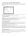
[Example]
To enable the pairing information to be preserved, following command sequences
need to be sent to the printer.
GS z AT*PAIRINFO=1 CR ^C
<1D 7A 41 54 2A 50 41 49 52 49 4E 46 4F 3D 31 0D 03>h
Printer power is turned off by receiving this command.
Print result at power on after receiving this command as follows.
********************************
BLUETOOTH INIT COMMANDS:
AT*PAIRINFO=1
OK
********************************
— 63 —
BLACK MARK FUNCTION
ESC l n
[Function]
Specify/canceling black mark function
[Code]
<1B>H<6C>H<n>
[Range]
n = 0 or 1
[Outline]
Specifying / canceling the black mark function.
n (Hex)
0
1
Type
Canceling black mark function
Specifying black mark function
[Caution]
Black mark function uses PE sensor of CMP-10 for black mark sensor. Therefore, the
condition of detecting paper end and detecting open cover is changed in this mode.
[Default]
n=0
[See also]
FF Note on Next page
FF
[Function]
Printing and paper feeding to the black mark position
[Code]
<0C>H
[Outline]
This command prints the data in the printer buffer and searches for black mark. It is
ignored if black mark function is not specified.
[Caution]
This command is valid only when black mark function is specified.
[See also]
ESC l n Note on next page
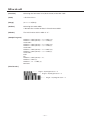
— 64 —
Note for Black Mark Function
1.
Error detection at black mark mode
Paper end is checked during printing but black mark is not checked.
After receiving FF command, printer checks black mark and paper end. Once black is detected and white
is detected again within 6 mm paper feed, it is determined as black mark. If the white is not detected
within 6 mm paper feed, it is determined as paper end.
After receiving FF command, if printer cannot detect back mark by feeding paper for 360 mm, printer
recognizes it as black mark detecting error. And the result is same as detecting paper end.
To release the error, it is necessary to put correct paper and press LF switch long.
2.
LF switch operation in black mark mode
Press short:
Feed one line
Press longer than 1 sec.: Feed paper to find next black mark. (Same as sending FF command)
3.
Switching Black mark mode
Black mark mode is set for disabled at factory.
Once black mark mode is enabled, it is effective till receiving disabling command or the battery connector
is disconnected.
By sending command ESC > which saves setting condition to NV memory, black mark mode can be kept
enabled even if battery connector is disconnected.
4.
Remarks for programming
As it is possible to print on black mark, if user does not want to print on the black mark, it have to be
taken care by user side program
5.
Remarks on handling
If the paper cover is open in black mark mode, there is a possibility to recognize it as detecting black
mark.
6.
Designing black mark paper
Black mark should be on recording side of the thermal paper.
Darkness of black mask should be 0.9 or more (PCS value).
The black mark size and position should be as follows.
B
C
A = 4 - 6 mm
B = 15 mm or more
C = 20 – 360 mm
The distance from PE sensor and print head is approx. 7.5 mm.
— 65 —
Printing direction
A
3. CHARACTER CODES TABLE
WPC1252
— 66 —
4. Setup menu function (After Ver2.20)
Make sure the printer power is off. Press ON/OFF switch and keep pressed for about 5 seconds until .LED is
changed to red and leave the switch. Then buzzer beeps and printer prints current setting and goes to setup
menu as follows.
Example
DISCOVERABILITY:
PAIRING INFO SAVING:
MEMORY SWITCHES:
BAUD RATE:
POWER OFF TIME:
PRINT DENSITY:
MAX IrDA SPEED 57600:
YES
YES
00000000
9600
10 min
100%
NO
SETUP MENU
<ON/OFF> - NO, <LF> - YES
CHANGE DISCOVERABILITY ?
The setting can be done by choosing NO (ON/OFF switch) or YES (LF switch) against coming up questions.
The details of each menu as follows.
(Following items A and B are shown when Bluetooth function is available.)
A. CHANGE DISCOVERABILITY ?
If you want to change the discoverability setting of Bluetooth, choose YES here. If not, choose NO and go to
next item.
If you choose YES, another question “SET DISCOVERABILITY ON ?” shows up. Choose YES for
DISCOVERABILITY ON or NO for DISCOVERABILITY OFF and go to next item.
However, even if the setting is YES, discoverability becomes off by pairing (bonding).
Default setting is YES (Discoverable).
The setting change does not affect the unit without Bluetooth module.
B. CHANGE PAIRING INFO SAVING ?
If you want to change the setting of enable/disable pairing information saving, choose YES here. If not,
choose NO and go to next item.
If you choose YES, another question “PAIRING INFO SAVING ON ?” shows up then Choose YES for Enable
pairing information saving or choose NO for disabling pairing information saving and go to next item.
Default setting is YES (enable pairing information saving)
The setting change does not affect the unit without Bluetooth module.
(Supplementary notes)
This setting must be YES for pairing (bonding). If the pairing is enabled, you can set authentication or encryption
and communicated with paired device becomes smooth.
If the condition for authentication is cleared, PIN code(PASS Key) is required to enter at the first time to
communicate to the host machine. The default pin code is last 4 digit of BD address of Bluetooth module. BD
address is 12 digit number printed on self test as Address. When you enter the PIN code, please use capital
letter for A-F.
C. CHANGE MEMORY SWITCHES ?
If you want to change memory switch setting, choose YES here and if not, choose NO and go to next item.
If you choose YES, questions like “SET SWITCH 1 ?” show up. Question is repeated from SWITCH 1 to
SWTICH 8.
If you want to set the memory switch value to 1, choose YES. If you want to set the memory switch value to
0, choose NO. After choosing the value of SWTICH 8, next menu item is printed.
Default value of all memory switches is 0.
— 67 —
D. CHANGE BAUD RATE ?
If you want to change the baud rate of serial communication, choose YES here and if not, choose NO and go
to next items.
If you choose YES, baud rate choice such as “1200 bps ?” are shown continuously. If the baud rate is right
one, choose YES and if not, choose NO.
When YES is chosen, printer prints next menu items.
The choice of baud rate are 1200, 2400, 4800, 9600, 19200, 38400, 57600, 115200 bps. The default setting is
9600 bps.
E. CHANGE AUTO POWER OFF TIME ?
If you want to change the auto power off time setting, choose YES here and if not, choose NO and go to next
item.
If you choose YES, choice of time length such as “5 min ?” are shown continuously. If the time is right one,
choose YES and if not, choose NO. When YES is chosen, printer prints next menu items.
The choice of time length is 5, 10, 15, 20, 25, 30, 45, 60 min.
If you want to set to the time not in this choice, you can set the time by command. The default setting is 10
min.
F. CHANGE PRINT DENSITY ?
If you want to change the print density, choose YES here and if not, choose NO and go to next item.
If you choose YES, density choice such as “70 % ?” are shown continuously. If the density is right one,
choose YES and if not, choose NO.
When YES is chosen, printer prints next menu items.
Choice of density is 70%, 80%, 90%, 100%, 120%, and 150%.
Default density setting is 100%.
G. CHANGE IrDA MAX SPEED ?
If you want to change Max speed of IrDA to 57600 bps, choose YES here and if not, choose No and go to next
item.
If you choose YES, another question “LIMIT SPEED TO 57600 bps ?” shows up. Then choose YES or NO.
When you choose either one, printer prints next menu items. Default setting is NO.
If the communication via IrDA is not stable, please try to set YES.
H. SAVE SETTINGS ?
During the menu setting, if YES is chosen somewhere, this items is printed. (If only NO is chosen, printer
does not print this item and turn the power off.)
If you want to save the changed setting, choose YES here and if not, choose NO.
If YES is not chosen, the changed setting will not be lost.
If YES is chosen printer prints “HARDWARE SETTING SAVED !” then print new setting then turn the power
off.
If NO is chosen, printer prints “HARDWARE SETTING NOT SAVED !” then turn the power off.
Caution
Setting values exist in 2 areas. One is in RAM and the other one is in flash. Setup menu changes both
settings. Settings in RAM are valid for the actual usage and it can be printed by self test. The setting values
printed during menu setup are from flash. (There is a command to save the setting in RAM to flash. If the
setting in RAM is destroyed by some reason, the setting in flash is loaded to RAM.) Setting in RAM can be
changed by a command. If you do not save the changed value to flash, difference exists between RAM and
flash.
— 68 —
The list of choice in the setup menu
Top question items
Additional questions
(Bold items is default value.)
YES (ON/OFF Switch)
NO (LF Switch)
CHANGE DISCOVERABILITY ?
SET DISCOVERABILITY ON?
Discoverability ON
Discoverability OFF
CHANGE PAIRING INFO SAVING ?
PAIRING INFO SAVING ON ?
Enable Pairing Info Saving
Disable Pairing Info Saving
CHANGE MEMORY SWITCHES ?
SET SWITCH 1 ?
Memory switch 1 = 1
Memory switch 1 = 0
(See the table below)
SET SWITCH 2 ?
Memory switch 2 = 1
Memory switch 2 = 0
SET SWITCH 3 ?
Memory switch 3 = 1
Memory switch 3 = 0
SET SWITCH 4 ?
Memory switch 4 = 1
Memory switch 4 = 0
SET SWITCH 5 ?
Memory switch 5 = 1
Memory switch 5 = 0
SET SWITCH 6 ?
Memory switch 6 = 1
Memory switch 6 = 0
SET SWITCH 7 ?
Memory switch 7 = 1
Memory switch 7 = 0
SET SWITCH 8 ?
Memory switch 8 = 1
Memory switch 8 = 0
1200 bps?
Baud rate 1200 bps
2400 bps ?
Baud rate 2400 bps
CHANGE BAUD RATE ?
CHANGE AUTO POWER OFF TIME ?
CHANGE PRINT DENSITY ?
CHANGE IrDA MAX SPEED ?
4800 bps ?
Baud rate 4800 bps
9600 bps ?
Baud rate 9600 bps
19200 bps?
Baud rate 19200 bps
38400 bps?
Baud rate 38400 bps
57600 bps?
Baud rate 57600 bps
115200 bps?
Baud rate 115200 bps
5 min ?
Auto power off 5 min
10 min ?
Auto power off 10 min
15 min ?
Auto power off 15 min
20 min ?
Auto power off 20 min
25 min ?
Auto power off 25 min
30 min ?
Auto power off 30 min
45 min ?
Auto power off 45 min
60 min ?
Auto power off 60 min
70 % ?
70 % density
80 % ?
80 % density
90 % ?
90 % density
100 % ?
100 % density
120 % ?
120 % density
150 % ?
150 % density
LIMIT SPEED TO 57600 bps ?
IrDA Max speed 57600 bps
Not choose this baud rate
Not choose this time length
Not choose this density
IrDA Max speed 115200 bps
"CHANGE DISCOVERABILITY ?" and "CHANGE PAIRING INFO SAVING ?" are shown when Bluetooth function is
available.
Memory switches
Item
OFF(0)
ON(1)
1
Shape of zero
With slash
No slash
2
CR code
Ignored
Works as LF
3
Default font
Font A
Font B
4
Print “Low Battery”
Valid
Invalid
5
Auto Status Back
Invalid
Valid
6
Not defined
-
-
7
IrDA Protocol
Valid
Invalid (Not recommended)
8
No use
-
-
— 69 —
YES = ON/OFF SWITCH
NO = LF SWITCH
Hold ON/OFF till LED changes to red.
Current settings are printed.
CHANGE DISCOVERABILITY ?
NO
YES
SET DISCOVERABILITY ON ?
YES or NO
YES
PAIRING INFO SAVING ON ?
CHANGE PAIRING INFO SAVING ?
NO
YES or NO
YES
CHANGE MEMORY SWITCHES ?
SET SWITCH 1?
YES or NO
NO
SET SWITCH 8 ?
YES or NO
CHANGE BAUD RATE ?
YES
1200 bps ?
NO
NO
YES
115200 bps ?
YES or NO
CHANGE AUTO POWER OFF TIME ?
YES
5 min ?
NO
NO
YES
60 min ?
YES or NO
YES
70 % ?
CHANGE PRINT DENSITY ?
NO
NO
YES
150 % ?
YES or NO
YES
LIMIT SPEED TO 57600 bps ?
CHANGE IrDA MAX SPEED ?
NO
YES or NO
SAVE SETTINGS ?
NO
YES
HARDWARE SETTING SAVED !
New settings are printed.
Power off automatically.
HARDWARE SETTING NOT SAVED !
Power OFF automatically.
— 70 —
5. PROGRAMMING CONSIDERATIONS
5.1 Notes at Lowered Battery Voltage
When battery is low, highly loaded printing such as printing of graphics with much black area may cause
power off during printing.
When executing high loaded printing, charging the battery before lowing of battery voltage is recommended
while keeping checking the information on the battery by the use of relevant command.
5.2 Notes on Printing After Paper Cutting
When the paper is cut by manual cutter, paper is likely to be caught by the cutter.
Therefore, in printing the first line just after cutting, the printing may be compressed in vertical direction.
When starting printing, feed one line without printing to prevent compressed printing.
— 71 —
6. SERIAL INTERFACE
6.1 Specifications
(1)
Data transfer system
Asynchronous, half duplex
(2)
Baud rates
1200, 2400, 4800, 9600, 19200, 38400, 57600, 115200 bps (Selectable by command)
(3)
Serial data configuration
Start bit: 1 bit
Data bit: 8 bits Fixed
Parity bit: No parity
Stop bit: 1 bit
(4)
Signal polarity
RS-232C
• Mark = logic “1” (–3V ~ –12V)
• Space = logic “0” (+3V ~ +12V)
(5)
Receiving data (RD signal)
RS-232C
• Mark = logic “1” (–3V ~ –12V)
• Space = logic “0” (+3V ~ +12V)
(6) Transmission control (TD signal)
DC1 code (11H) X-ON: Data reception is available
DC3 code (13H) X-OFF: Data reception is not available
6.2. Connector Pin Configuration
Pin No.
3
6
7
11
14
15
Signal
TXD
+5V
RXD
RTS
—
GND
Direction
Function
Output Transferred data
—
Input
Received data
Input
Auto Turn On
Communication mode setting
—
(InfraRed or Serial)
—
Connector
Printer side:
Connector used on StarTac (Motorola)
PC side
9 pin D-SUB
Cable
— 72 —
Pin No. of Cable
No. 2 pin of D-Sub 9 pins
No connection
No. 3 pin of D-Sub 9 pin
No. 7 pin of D-Sub 9 pin
No. 5 pin of D-Sub 9 pin
No. 5 pin of D-Sub 9 pin
6.3 Explanation of Input/Output Signals
(1)
RXD
This is signal, receiving data from the host. On occurrence of framing error, overrun error, or parity
error, the data is printed as “?”.
(2)
TXD
This signal is for data flow control by X-ON/X-OFF. If data remains in the printer’s input buffer is 2048
bytes or less, the printer transfers a DC3 (13H: Data Receive Not Ready) signal to the host. If data in the
input buffer exceeds 4096 bytes, the printer transfers a DC1 (11H: Data Receive Ready) signal to the host.
(3)
Vcc
This is a power supply (+5 V). The signal is not use in the standard serial cable!
(4)
GND
This is a GND on the circuit.
(5)
Auto turn-on
The printer can be turned on by using RTS signal from the host
CAUTION: Ensure that the RTS signal is deactivated when your application software not using the printer as
auto turn-off function is disabled when RTS is active
14, 15 pin (Communicate mode setting)
Using dedicated cable makes these pin short-circuited.
If these pins are short-circuited, printer sets the communicate mode to serial communication.
If these pins are not short-circuited, printer set the communication mode to infrared.
6.4 Error Detection
Framing and overrun are detected. On detection of any error, the data are stored in the buffer as “?”.
(1)
Framing Error
With “space” state having been detected on detection of a stop bit, error takes place. The data are
stored in the buffer as “?”.
(2)
Overrun Error
On detection of an overrun error, the data are stored in the buffer as “?”.
6.5 Buffering
This printer incorporates 64K byte buffer. This allows most print jobs to by fully buffered so that the host can
continue quickly.
— 73 —
6.6 Electrical Characteristics
RS-232C Circuit
Input (RXD)
<Printer side>
<Host side>
Equivalent MAX232
Output (TXD)
<Printer side>
<Host side>
Equivalent MAX232
— 74 —
7. INFRARED COMMUNICATION SPECIFICATIONS
7.1 Basic Specification
(1)
Interface:
Infrared transceiver mode
(2)
Data transfer system
Half duplex
Asynchronous
(3)
Baud rate:
9600, 19200, 38400, 57600, 115200 bps
(Max baud rate can be set at 57600 bps by command.)
(4)
Data configuration
Data length
Stop bit
Parity
(5)
Logic level
Low Level = 0
High Level = 1
(6)
Transport wave:
Wave length 850 - 900 nm
(8)
Distance
Less than 80 cm
(9)
Receiving angle
Left 15º
Top 15º
8 bit
1 bit
None
Right 15º
Bottom 15º
7.2 Supported Protocol
(1)
IrDA version
1.0
(2)
Flow control
IrDA standard
(3)
Supported Protocol
IrComm 3 wire raw
IrLPT
IrLMP
IrLAP
(4)
Protocol Layer
IrComm 3 Wire raw
IrLPT
Ir Link Management - MUX - IrLMP
Ir Link Access Protocol - IrLAP
Async Serial-IR
9600-115.2 kb/s
(5)
Applicable protocol
Class:
Attribute:
IrDA:IrCOMM or IrDA:IrLPT
IrDA:IrLMP:LsapSel
via IrLMP
— 75 —
8. MECHANICAL SPECIFICATION
8.1 Printer Mechanism
(1)
Print method
Line thermal printing
(2)
Number of dot
384 dot/line
(3)
Head density
8 dot/mm
(4)
Print width
48 mm
(5)
Sensors
Head temperature
Paper end
Head-up
Thermistor
Photo Interrupter
Mechanical switch
(6)
Paper
Paper width
Paper thickness
Recommended paper
Outside diameter
58 mm+0/–1
65 µm
TF50KS-E2D (Nippon Paper)
Max 40 mm or 50 mm (by model)
(7)
Paper feed force
0.49N or more
(8)
Paper keep force
0.78N or more
(9)
Reliability
Head life
6 million lines (Room temperature normal humidity)
100 million pulses
50 km
15 million lines (Duty 12.5%)
MCBF
8.2 Card Reader
(1)
Supported track
ISO (JIS) 1, 2, 3
(2)
Card thickness
0.76 mm +/–0.08 mm
(3)
Specifications of each track
Track
Record density
Record capacity
ISO-1
210 BPI
79 characters (7 bits)
ISO-2
75 BPI
40 characters (5 bits)
8.3 Lifetime of Mechanical Parts
Power switch: 45,000 times (30 times/day × 300 days × 5 years)
— 76 —
ISO-3
210 BPI
107 characters (5 bits)
9. POWER RELATED SPECIFICATIONS
9.1 Battery
(1)
Battery type
Lithium-ion battery pack
(2)
Maximum capacity
2000 mAh
(3)
Number of sells
2
(4)
Maximum output voltage
4.2V/Cell
(5)
Cut-off voltage
2.75V/Cell
(6)
Standard charge
1000 mA, 23ºC, 4.2V/Cell, 3 hours charge
(7)
Initial capacity
1950 mAh or more
(After standard charge and discharge 400 mA till cut off at 23ºC,
then measure the capacity)
(8)
Initial impedance
100m ohm or less
(9)
Cycle life capacity
1400 mAh or more
(Repeat the routine - Standard charge + discharge 2000 mA till cut-off –
299 times and leave one day, then measure in same condition as initial
capacity)
(10) Discharge by temperature
–10ºC 50%
0ºC 80%
23ºC 100%
45ºC 100%
(After standard charge and discharge 1000 mA till cut-off)
(11) Storage
1600 mAh or more
(After standard charge, keep it at 23ºC in 30 days then discharge
1000 mA at 23ºC till cut-off)
9.2 Power Management
(1) Printable lines
40,000 lines or more
(Room temperature, full charge, ASCII slide pattern printing)
(2) Auto power off time
5 minutes (can be changed between 1 and 60 minutes)
(3) Low battery detection voltage
6.7V
(4) Battery release voltage
5.5V
9.3
Power Consumption
Average
1.45A (ASCII slide pattern printing)
Peak
2A
Stand-by
80 mA
— 77 —
10. AC ADAPTOR
(1)
Input voltage
100V ~ 240V AC (50/60 Hz)
(2)
Input current
250 mA
(3)
Rated output
9V ±5%
(4)
Efficiency
65% or more (AC 100V/50 Hz full load)
70% or more (AC 240V/50 Hz full load)
(5)
Ripple and noise voltage
Less than 150 mVp-p (9 VDC)
(6)
Insulation test
More than 100M ohm
(DC 500V, 1 minute, between primary and secondary circuit and chassis)
(7)
Leakage current
0.25 mA or less (AC 240V/50 Hz)
(8)
Temperature rise
45K or less on case surface (100 VAC/50 Hz full load @25°C)
(9)
Over voltage protection
120% - 150%
(10) Overload protection current
1.8 - 3.5A (AC 100-240, 25°C)
(11) No load power consumption
3W or less (AC 240V, 25°C)
(12) Safety standard
UL, C-UL, PSE (10AD-JU)
VDE, GS, CE (10AD-E)
(13) Size
10AD-JU - 75 mm (L) × 50 mm (W) × 30 mm (H)
(14) Case material
94V-1
(15) Cable
1828.8 mm UL2468#22 × 2C
(16) Plug
3.5 × 1.3 × 9.5S
(17) Polarity
Center ”+”
(18) Weight
104 g ±5g
11. EMI STANDARD
VCCI Class B
FCC Class B
EN55022
— 78 —