1
LINE THERMAL PRINTER/
PRESENTER UNIT
MODEL PPU-231
User’s Manual
PPU-231 User’s Manual
Declaration of Conformity
This printer conforms to the following Standards:
Low Voltage Directive 73/23/EEC, 93/68/EEC and the EMC Directive 89/336/EEC,
92/31/EEC, 93/68/EEC.
LVD : EN60950
EMC : EN55022
Class A
EN61000-3-2
EN61000-3-3
EN55024
This declaration is applied only for 230V model.
WARNING : This is a Class A products. In a domestic environment this product may cause radio interference in
which case the user may be required to take adequate measures.
CITIZEN is a registered trade mark of CITIZEN WATCH CO., LTD., Japan
CITIZEN es una marca registrada de CITIZEN WATCH CO., LTD., Japón
CITIZEN
PPU-231 User’s Manual
IMPORTANT SAFETY INSTRUCTIONS
•
•
•
•
•
•
•
•
•
•
•
•
•
Read all of these instructions and save them for future reference.
Follow all warnings and instructions marked on the product.
Unplug this product from the wall outlet before cleaning. Do not use liquid or aerosol cleaners. Use
a damp cloth for cleaning.
Do not use this product near water.
Do not place this product on an unstable cart, stand or table. The product may fall, causing serious
damage to the product.
Slots and openings on the back or bottom of the case are provided for ventilation. To ensure reliable
operation of the product and to protect it from overheating, do not block or cover these openings. The
openings should never be blocked by placing the product on a bed, sofa, rug of other similar surface.
This product should never be placed near or over a radiator or heater. This product should not be
placed in an built-in installation unless proper ventilation is provided.
This product should be operated from the type of power source indicated on the marking label. If you
re not sure of the type of power available, consult your dealer or local power company.
Do not allow anything to rest on the power cord. Do not place this product where the cord will be
walked on.
If an extension cord is used with this product, make sure that the total of the ampere ratings of the
products plugged into the extension cord does not exceed the extension cord ampere rating. Also,
make sure that the total of all products plugged into the wall outlet does not exceed 15 amperes.
•Never push objects of any kind into this product through cabinet slots as they may touch dangerous
voltage points or short out parts that could result in a risk of fire or electric shock. Never spill liquid
of any kind on the product.
Except as explained elsewhere in this manual, do not attempt to service this product by yourself.
Opening and removing the covers that are marked “Do Not Remove” may expose you to dangerous
voltage points or other risks. Refer all servicing on those compartments to service personnel.
•Unplug this product from the wall outlet and refer servicing to qualified service personnel under the
following conditions:
A. When the power cord or plug is damaged or frayed.
B. If liquid has been spilled into the product.
C. If the product has been exposed to rain or water.
D. If the product does not operate normally when the operating instructions are followed. Adjust only
those controls that are covered be the operating instructions since improper adjustment of other
controls may result in damage and will often require extensive work by a qualified technician to
restore the product to normal operation.
E. If the product has been dropped or the cabinet has been damaged.
F. If the product exhibits a distinct change in performance, indicating a need for service.
Please keep the poly bag which this equipment is packed in away from children or throw it away to
prevent children from putting it on. Putting it on may cause suffocation.
CITIZEN
PPU-231 User’s Manual
WICHTIGE SICHERHEITSANWEISUNGEN
•
•
•
•
•
•
•
•
•
•
•
Lesen Sie die nachfolgenden Anweisungen sorgfältig durch und bewahren Sie sie auf.
Befolgen Sie alle auf der Einheit vermerkten Hinweise und Anweisungen. Vor dem Reinigen
grundsätzlich Stecker aus der Steckdose ziehen. Keine Flüssigkeiten oder Aerosolreiniger benutzen.
Nut mit einem feuchten Tuch abwischen.
Die Einheit darf nicht in der Nähe von Wasser aufgestellt werden.
Einheit nicht auf einem unstabilen Wagen, Stand oder Tisch aufstellen. Der Einheit könnte
herunterfallen und dabel beschädigt werden.
Schlitze und Öffnungen im Gehäuse, in der Rückwand und im Boden dienen der Belüftung. Sie
dürfen keinesfalls zugedeckt oder blockiert werden, da sich die Einheit sonst überhitzt. Einheit nicht
auf ein Bett, Sofa, Teppich oder dergleichen stellen. Einheit nicht in der Nähe eines Heizkörpers
aufstellen. Einheit darf nicht eingebaut werden, falls nicht für ausreichende Belüftung gesorgt ist.
Einheit nur mit der auf dem Typschild angegebenen Spannung betreiben. Wenn Sie sich nicht sicher
sind, fragen Sie ihren Händler oder ihr zuständiges Elektrizitätswerk.
Nichts auf das Stromanschlußkabel stellen. Kabel muß so verlegt werden, daß man nicht darauftreten
kann.
Ein etwaiges Verlängerungskabel muß der Stromstärke aller daran angeschlossenen Geräte entsprechen.
Keine Gegenstände in die Gehäuseschlitze schieben.
Einheit darf nur da gewartet werden, wo im Handbuch angegeben, Öffnen und. Abnehmen von
Abdeckungen, die mit “Do not remove” gekennzeichenet sind, könnte gefährliche spannungführende
Stellen oder sonstige Gefahrenpunkte freilegen. Die Wartung solcher Stellen darf grundsätzlich nur
von besonders ausgebildetem Fachpersonal vorgenommen werden.
A. Wenn das Stromanschlußkabel oder der Stecker beschädigt oder durch-gescheuert ist.
B. Wenn Flüssigkeit auf der Einheit verschüttet wurde.
C. Wenn die Einheit im Regen gestanden hat oder Wasser darauf verschüttet wurde.
D. Wenn die Einheit trotz genauer Befolgung der Betriebsvorschriften nicht richtig arbeitet. Nur die
in der Bedienungsanleitung angegebenen Einstellungen vornehmen. Ein Verstellen anderer
Bedienungselemente könnte die Einheit beschädigen und macht umständliche Arbeiten eines
qualifizierten Technikers erforderlich, um die Einheit Wieder auf den normalen Betrieb einzustellen.
E. Wenn die Einheit heruntergefallen ist oder das Gehäuse beschädigt wurde.
F. Wenn die Einheit in seiner Leistung nachläßt.
Bitte halten Sie den Kunststoffbeutel, in den die Ware verpackt ist, von Kindern entfernt, oder werfen
Sie ihn weg, damit er nicht in die Hande von Kindern gerät. Das Überstülpen des Beutels kann zum
Ersticken führen.
Lärmemission kleiner 70dBA
CITIZEN
PPU-231 User’s Manual
<CAUTIONS>
1. Prior to using the equipment, be sure to read this User's Manual thoroughly. Please keep it handy for reference
whenever it may be needed.
2. The information contained herein may be changed without prior notice.
3. Reproduction of part or all of this User's Manual without permission is strictly prohibited.
4. Never service, disassemble, or repair parts that are not mentioned in this User's Manual.
5. Note that we will not be responsible for damages attributable to a user's incorrect operation/ handling or an
improper operating environment.
6. Operate the equipment only as described in this User's Manual; otherwise accidents or problems may result.
7. Data are basically temporary; they cannot be stored or saved permanently or for a long time. Please note that
we will not be responsible for damages or losses of profit resulting from losses of the data attributable to
accidents, repairs, tests, and so on.
8. If you have any questions or notice any clerical errors or omissions regarding the information in this manual,
please contact our office.
9. Please note that, notwithstanding Item 8 above, we will not be responsible for any effects resulting from
operation of the equipment.
CITIZEN
PPU-231 User’s Manual
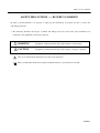
SAFETY PRECAUTIONS ----- BE SURE TO OBSERVE
In order to prevent hazards to an operator or other persons and damage to property, be sure to observe the
following precautions.
• The following describes the degrees of hazard and damages that can occur if the given instructions are
neglected or the equipment is incorrectly operated.
WARNING
Negligence of this precaution may result in death or serious injury.
CAUTION
Negligence of this precaution may result in injury or damage to property.
This is an illustration mark used to alert your attention.
This is an illustration mark used to indicate such information as an instruction or the like.
CITIZEN
PPU-231 User’s Manual
WARNING
z Never handle the equipment in the following manners, as it may break, become out of order, or overheat
causing smoke and resulting in fire or electric shock.
If the equipment is used in an abnormal condition, such as when broken, then problems, smoke
emission, abnormal odor/noise, and fire can result. If an abnormal condition exists, be sure to
disconnect the power plug from a plug socket, and contact our dealer. Never repair the equipment on
your own - it is very dangerous.
• Do not allow the equipment to receive a strong impact or shock, such as kicking, stomping, hitting,
dropping, and the like.
• Install the equipment in a well-ventilated place. Do not use it in such a manner that its ventilation port
will be blocked.
• Do not install the equipment in a place like a laboratory where chemical reactions are expected, or in a
place where salt or gases are contained in the air.
• Do not connect/disconnect a power cord or a data cable, while holding the cable. Do not pull, install,
use, or carry the equipment in such a manner that force will be applied to the cables.
• Do not drop or insert any foreign substances, such as clips or pins, into the equipment.
• Do not spill any liquid or spray any chemical-containing liquid over the equipment. If any liquid is
spilled on it, turn off the power, disconnect the power cable and power cord from the plug socket, and so
on, and contact our dealer.
• Never disassemble or remodel the equipment. Negligence of this may cause fire or
electric shock.
• Use the equipment only with the specified commercial power supply and AC adapter. Negligence of
this may result in fire, electric shock, or problems.
• If you drop or break the AC adapter, or if water or the like gets inside it, unplug it immediately from the
socket and contact your dealer.
• Do not damage, break, process, bend/pull by force, twist, or head an AC adapter cord. Also, do not put
a heavy substance on it or heat it. The AC adapter cord could be broken, resulting in fire, electric
shock, or trouble. If the AC adapter cord is damaged, contact our dealer.
• Do not connect/disconnect the AC adapter with wet hands.
• Do not overload a single electrical outlet, using a table tap or a current tap socket.
z An equipment packing bag must be discarded or kept away from children. A child can suffocate if the
bag is placed over the head.
CITIZEN
PPU-231 User’s Manual
PRECAUTIONS FOR INSTALLATION
• Do not use or store the equipment in a place exposed to fire, moisture, or direct sunshine, or in a place
near a heater or thermal device where the prescribed operating temperature and humidity are not met, or
in a place exposed to much oil, iron powder, or dust. The equipment may become out of order, emit
smoke, or catch fire.
• Do not install or use the equipment in a place like a laboratory where chemical reactions are expected,
or in a place where salt or gases are contained in the air. There is a danger of fire or electric shock.
• Install the unit on a flat, stable desk or table that is free from vibration, in a well-ventilated place.
• Do not install the unit at a location where its operation could be hindered.
• Do not place anything on the unit or leave small objects, like a clip or pin, around it. A foreign object
could cause trouble if it gets inside.
• Do not use any sharp-pointed object, such as a pen, for example, to touch the operation panel of the unit.
It could cause trouble.
• Do not use the equipment near a radio or TV receiver. Do not share the power from a plug socket a
radio or TV receiver is connected to. It may cause a reception problem.
• Use the equipment only at the specified power supply, voltage and frequency. Otherwise, it may emit
smoke and catch fire or cause other problems.
• Connect only the specified power source. Use of an unspecified power source could cause trouble or
smoke/fire.
• Confirm that a plug socket used for connection has sufficient capacity.
• Avoid connecting a power cable to a plug socket shared by other devices or extending the wiring too far.
It may result in the cable catching fire or a power outage. Also, do not step on or apply an excessive
force (Pull, load) to the cable, and do not use the unit with such a force applied to it.
• Never connect a grounding cable (Frame ground) to a gas pipe. There is a danger of explosion.
When connecting or disconnecting the grounding cable, be sure to disconnect the power cable and the
power plug from the plug socket.
• When connecting/disconnecting the cables, be sure to turn off the power first, including the connected
side, and then connect/disconnect them, holding a plug and a connector. Pulling the cable itself could
cause it to snap or become damaged.
• Connect a power cable or a connector cable securely. If a reverse-polarity connection is made, internal
elements may be broken or a mating device may be adversely affected.
• Use a shielding wire or twisted pair wire for a signal line, in order to minimize noise effect. Do not
route the cable too long or connect it to a noisy device. Connection to a noisy device could cause
erroneous printing due to corrupt data, and so on.
• Use the equipment in an environment where there is a plug socket near the main body and you can
easily disconnect the power plug from it, to shut off the power.
• When the equipment will not be used for a long period of time, unplug it and remove the paper roll from
it.
• When transporting the equipment, remove the paper roll from the paper holder.
CITIZEN
PPU-231 User’s Manual
PRECAUTIONS FOR HANDLING
Do not handle the equipment in the following manners, because problems may result.
• Do not use any other power source besides the accessory AC adapter. Also, do not use the AC adapter
for other purposes.
• Do not print without paper.
• Do not drop or put any foreign object, such as a clip, pin, or the like, inside the unit.
• Do not spill any liquid or spray any chemical-containing liquid over the equipment.
• Never use a pointed object, such as a pen, to operate the operation panel.
• Do not use Scotch tape to fasten paper together for continuous use. It could damage the printing head.
• Never pull the set paper forcibly.
When opening/closing the unit cover, take care that the paper will
not be caught. It could cause the paper to jam.
• Be sure to use the specified paper. Use of other paper could deteriorate the print quality or cause a
problem with the printing head.
To Prevent Injury and Spreading of Damage
• Never touch the printing head, motor, or paper cutting blade. Your finger may be cut.
• During power-on or immediately after printing, do not touch electrical parts or moving parts, such as the
mechanism, motor, internal gear, etc. They may be very hot and can burn your hand/finger.
• Be careful to avoid bodily injure or damaging other objects with an edge of sheet metal.
• Should any error occur while operating the equipment, stop it immediately and disconnect the power
plug from the plug socket.
• Only a qualified serviceman is allowed to disassemble or repair the unit.
• Should a problem occur, leave solving it to our serviceman. Do not disassemble the equipment on
your own.
• When opening/closing the unit cover, and so on, be careful not to catch your hand or finger on the
equipment.
• After using the equipment, turn off the power switch and unplug the AC adapter from a plug socket.
CITIZEN
PPU-231 User’s Manual
DAILY MAINTENANCE
• At the time of maintenance, be sure to turn off the power switch of the unit and unplug it from the
socket.
• Use a dry soft cloth to wipe off stains and dust from the surfaces of the main body case. For severe
soiling, dip the cloth in water and wring it, for wiping off the soil. Never use organic solvents, such as
alcohol, thinner, trichlene, benzene, ketone, or chemical dusters.
• If the equipment is contaminated with paper powder, use a soft brush to clean it. Be careful not to
damage the printing head.
CAUTION: The printing head and motor are very hot. Be careful not to touch them immediately
after printing. Do not touch the heating surface of the head with a bare hand or
metal.
CITIZEN
PPU-231 User’s Manual
CONTENTS
1. OUTLINE ...............................................................................................................................................................1
1.1
Features ...................................................................................................................................................................... 1
1.2
Unpacking .................................................................................................................................................................. 1
2. BASIC SPECIFICATIONS ...................................................................................................................................2
2.1
Model Classifications ................................................................................................................................................. 2
2.1.1
PPU series (Printer/Presenter unit) .................................................................................................................... 2
2.1.2
Options .............................................................................................................................................................. 3
2.1.3
Miscellaneous .................................................................................................................................................... 4
2.2
Basic Specifications ................................................................................................................................................... 6
2.3
Paper Specifications ................................................................................................................................................... 7
2.3.1
Recommended Paper ......................................................................................................................................... 7
2.3.2
Printing Position ................................................................................................................................................ 7
2.3.3
Printing Head and Paper Cutter Layout ........................................................................................................... 8
3. OUTER APPEARANCE AND COMPONENT PARTS.....................................................................................9
3.1
PPU (Printer/Presenter Unit) ...................................................................................................................................... 9
3.2
Optional PHU (Paper Holding Unit) .........................................................................................................................11
4. OPERATION ........................................................................................................................................................12
4.1
Connecting the AC Adapter ..................................................................................................................................... 12
4.1.1
Using the Power Connector ............................................................................................................................. 12
4.1.2
Connecting a Power Cable to the Control PCB ............................................................................................... 13
4.2
Connecting the Interface Cable ................................................................................................................................ 14
4.3
Inserting the Paper.................................................................................................................................................... 17
4.4
How to Remove Remaining Paper Roll ................................................................................................................... 18
4.5
Eliminating the Paper Jam........................................................................................................................................ 19
4.5.1
Eliminating a Jam in the Printer Mechanism................................................................................................... 19
4.5.2
Eliminating a Jam in the Presenter .................................................................................................................. 20
4.6
Releasing a Locked Cutter........................................................................................................................................ 21
4.7
FEED Switch Function............................................................................................................................................. 21
4.8
Paper End Function .................................................................................................................................................. 21
4.9
Connecting the PHU (Paper Holding Unit) .............................................................................................................. 22
4.10 Paper Near End Function (When Using the PHU) ................................................................................................... 22
4.11 Auto-Loading Function ............................................................................................................................................ 23
4.12 Self-Print Function ................................................................................................................................................... 23
4.13 Presenter Control ....................................................................................................................................................... 23
CITIZEN
PPU-231 User’s Manual
5. DIP SWITCH SETTING.....................................................................................................................................24
5.1
Location of DIP Switch ............................................................................................................................................ 24
5.2
DIP Switch Function ................................................................................................................................................ 25
6. PARALLEL INTERFACE ..................................................................................................................................27
6.1
Specifications ........................................................................................................................................................... 27
6.2
Connector's Pin Configuration.................................................................................................................................. 27
6.3
Input and Output Signals .......................................................................................................................................... 28
6.3.1
Input and Output Signals ................................................................................................................................. 28
6.3.2
Electrical Characteristics ................................................................................................................................. 29
6.3.3
Timing Chart.................................................................................................................................................... 30
6.3.4
Data Receiving Control ................................................................................................................................... 30
6.3.5
Buffering.......................................................................................................................................................... 30
7. SERIAL INTERFACE.........................................................................................................................................31
7.1
Specifications ........................................................................................................................................................... 31
7.2
Connector's Pin Configuration.................................................................................................................................. 31
7.3
Input and Output Signals .......................................................................................................................................... 32
7.3.1
Input and Output Signals ................................................................................................................................. 32
7.3.2
Data Configuration .......................................................................................................................................... 33
7.3.3
Error Detection ................................................................................................................................................ 33
7.3.4
Data Receiving Control ................................................................................................................................... 34
7.3.5
Buffering.......................................................................................................................................................... 34
7.3.6
Electrical Characteristics ................................................................................................................................. 34
8. POWER CONNECTOR......................................................................................................................................35
9. MAINTENANCE AND SERVICE .....................................................................................................................36
10. PRINT CONTROL FUNCTIONS......................................................................................................................37
10.1 Command List ........................................................................................................................................................... 37
10.2 Command Details ..................................................................................................................................................... 39
10.2.1 Description of Items.......................................................................................................................................... 39
10.2.2 Details ............................................................................................................................................................... 40
11. CHARACTER CODES TABLE..........................................................................................................................81
11.1 International (Page 0)................................................................................................................................................. 81
11.2 Japanese (Page 1) ..................................................................................................................................................... 82
11.3 International Character Code Table ........................................................................................................................... 83
CITIZEN
PPU-231 User’s Manual
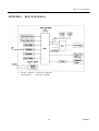
APPENDIX 1.
BLOCK DIAGRAM ......................................................................................................................84
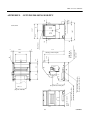
APPENDIX 2.
OUTLINE DRAWING FOR PPU.................................................................................................85
APPENDIX 3.
OUTLINE DRAWING FOR PHU................................................................................................86
CITIZEN
PPU-231 User’s Manual
1.
OUTLINE
Packed with features, this small line thermal printer/presenter has a wide range of uses: a terminal device for
various data communication, an instrumentation terminal, an outdoor information terminal or a device that
prints various tickets and coupons. Please read this manual thoroughly before you use the printer/presenter to
ensure it is implemented correctly.
1.1
Features
1.
Small, lightweight, and installable in a narrow area
2.
High speed and low noise, owing to line thermal print
3.
Long-life printing head and high reliability, owing to the simple mechanism
4.
Easy paper-loading, owing to the auto-loading function
5.
Built-in input buffer
6.
Capable of printing a bar code (Special command)
7.
You can choose where you attach the power connector, interface connector, etc.
8.
Large diameter paper roll support
1.2
Unpacking
When unpacking the package, confirm that the following parts are provided:
• Printer/Presenter unit
-------- 1 unit
• User's manual
-------- 1 copy
CAUTION
1)
Install the unit body on a flat and stable device.
2) Do not install the unit near a heater or in a place exposed to the direct sunshine.
3) Do not use the unit in a high-temperature, high-humidity, or contaminated environment.
4)
Do not allow dew condensation to form on the unit.
If such condensation should form, do not turn on the
power until it has completely gone away
5)
Use only the specified AC adapter.
Do not use it for any other purpose.
6)
If you do not use the unit for a long period, disconnect the power cable from the socket.
7)
Keep this manual carefully at hand for ready reference.t put the AC power cord close to a heating device.
1
CITIZEN
PPU-231 User’s Manual
2.
2.1
BASIC SPECIFICATIONS
Model Classifications
Classification is made according to the following naming system.
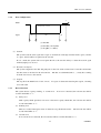
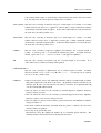
2.1.1
PPU series (Printer/Presenter unit)
PPU-231
P
U
M
Option
Model Name
M: Black mark detection
PPU-231: Standard Model
Character set
Interface
U: North America
R: Serial (RS-232C)
E: Europe
P: Parallel (Conforms to CENTRONICS)
For PPU-231 R U or E (Serial Interface):
The type of cable fixing screws for the serial interface connector depends on the destinations.
U: Inch type screws
E: mm type screws
2
CITIZEN
PPU-231 User’s Manual
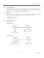
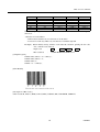
2.1.2
Options
(1) PHU series (Paper holding unit)
PHU-13 1
PNE Sensor
Model Name
1: 1 piece
PHU-131: Standard Model
2: 2 pieces
(2) 31AD series (Power supply unit)
31AD-U
Destinations
Model Name
U: North America (120 V AC)
E: Europe (230 V AC)
3
CITIZEN
PPU-231 User’s Manual
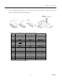
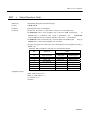
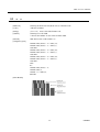
2.1.3
Miscellaneous
The following models are sold as single units.
(1) PRU series (Presenter unit)
PRU-130
(2) PMU series (Printer mechanism unit)
PMU-230
M
Option
M: Black mark detection
4
CITIZEN
PPU-231 User’s Manual
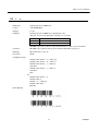
(3) BD2 series (Control PCB with accessories)
BD2-380A
P
U
Model Name
BD2-380A: Standard Model
Interface
Character set
R: Serial (RS-232C)
U: North America
P: Parallel (Conforms to CENTRONICS)
E: Europe
For BD2-380A R U or E (Serial Interface):
The type of cable fixing screws for the serial interface connector depends on the destinations.
U: Inch type screws
E: mm type screws
A more detailed specification description is listed in the PHU, PRU, PMU, BD2 user's manual, which is a
separate booklet.
5
CITIZEN
PPU-231 User’s Manual
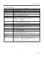
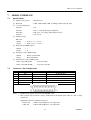
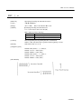
2.2
Basic Specifications
Item
Printing system
Printing width
Dot density
Printing speed
Printing columns and
character size
Line interval
Description
Line thermal dot printing
72 mm (576 dots/line)
8 dots/mm (Width, Length)
62.5 mm/sec. (At maximum), 500 dots/sec.
48 columns (12 × 24 Font A) 1.25 × 3.00 mm
64 columns (9 × 24 Font B) 0.88 × 3.00 mm
Initial value: 4.23 mm (1/6 inch)
Can be set with a command (1/203 inch at minimum)
Alphanumeric, Japanese, international characters
UPC-A, JAN(EAN) 13-/8-column, ITF, CODE 39, CODE 128, CODABAR
Thermal paper roll
Width
: 80 mm
Outer diameter
:φ203 mm (Max.), (When using PHU)
Inner diameter
:φ25.4 mm (Max.)
Thickness
: 60∼85µm
Length of normal issue
64 ∼ 305mm (Can be adapted to issue 457mm lengths)
2.5 ~ 12 inches(Can be adapted to issue 18 inch lengths)
Serial (RS-232C), Parallel (Conforms to CENTRONICS)
4 KB
ESC/POS
Paper near end sensor (When using PHU, position adjustable)
Paper end sensor (When using PMU)
Black mark sensor (Option)
24 V DC +/- 7%
100 W
PPU : 1.6 kg (Control PCB included)
PHU : 0.9 kg (Paper roll excluded)
PPU : 144.7 (W) × 160 (D) × 172 (H) mm
PHU : 132.2 (W) × 120 (D) × 125.2 (H) mm
*: Protruding parts are not included. For details, see Appendices 2 and 3.
Character types
Bar code type
Used Paper
(See Paper Specifications)
Presenter
Interface
Input buffer
Command
Sensors
Supply voltage
Power consumption
Weight
Outer dimensions
Operating temperature
and humidity
Storage
temperature
humidity
Reliability
5 ∼ 40°C, 35 ∼ 85 % RH (No dew condensation)
and
-20 ∼ 60°C, 10 ∼ 90% RH (No dew condensation)
Printing head life:
Pulse resistance
Wear resistance
: 50 million pulses or more (Print rate 12.5%)
: 30 km or more (With recommended thermal paper at normal
temperature and humidity)
Auto cutter life:
300,000 cuts (With recommended thermal paper at normal temperature and humidity)
6
CITIZEN
PPU-231 User’s Manual
2.3
Paper Specifications
2.3.1
Recommended Paper
• Type
: Thermal paper
• Paper width
: 80 + 0/- 1 mm
• Paper thickness
: 60 ∼ 85µm
• Roll diameter
: φ203 mm or less (When using PHU)
• Printing surface
: Outside of the roll (Surface)
• Recommended paper
: TF50KS-E, E2C (Monochrome) made by NIPPON SEISHI or its equivalent
• Core
: φ25.4 mm (Inner diameter)
CAUTION:
1)
Use of non-specified paper may cause irregularity of print density. If this is the case, use the DIP switch
to reset print density. (See 5. DIP SWITCH SETTING)
2.3.2
2)
Do not paste the paper to the core.
3)
If the paper comes in contact with a chemical or oil, it may discolor or lose a record.
4)
Do not rub the paper surface strongly with a nail or hard metal. It may discolor.
5)
Discoloring starts at about 70°C. Watch out for effects of heat, humidity, light, and so on.
Printing Position
7
CITIZEN
PPU-231 User’s Manual
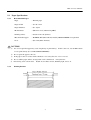
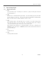
Printing Head and Paper Cutter Layout
Presenter Sensor Position
Paper Feed
Direction
Approx. 90 mm
Presenter Drive
Roller Position
Approx. 48 mm
Auto Cutter Position
Approx. 12 mm
Thermal Head Position (Printing Position)
Approx. 20 mm
6 mm
2.3.3
10 m m 20 mm
Black Mark
(Back Side)
8
CITIZEN
PPU-231 User’s Manual
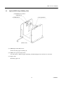
3.
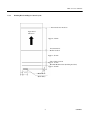
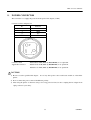
3.1
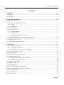
OUTER APPEARANCE AND COMPONENT PARTS
PPU (Printer/Presenter Unit)
(4) Presenter
(9) Knob
(8) Head-up Lever
(3) Power Connector
(10) Front Door
(1) POWER Switch
(2) FEED Switch
(5) Auto Cutter
Printer Mechanism Unit
(6) DIP Switches
(7) Interface Connector
9
CITIZEN
PPU-231 User’s Manual
(1) POWER switch
Turns on/off the power for the printer/presenter unit
(The POWER switch can be mounted either side of the unit.).
(2) FEED switch
Feeds the paper to exit the paper.
(3) Power connector
Connects to the optional AC adapter (31AD).
(The power connector can be mounted at any one of the 6 locations on the unit. See 4.1.1 ”Connecting
the AC Adapter”.)
(4) Presenter
Feeds the paper roll.
(5) Auto Cutter
Automatically cuts the printed paper by a command. Either partial cut or full cut is selectable.
(6) DIP switches
Initially set the printer/presenter unit at power-on and set the functions.
(7) Interface connector
Connects to a communication interface cable. There are two types, for serial and parallel interfaces.
(8) Head-up lever
Used when inserting the paper or exiting the paper.
(9) Knob
Use this to manually feed the paper.
(10) Front door
Open this door to remove remaining paper inside the presenter.
10
CITIZEN
PPU-231 User’s Manual
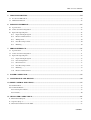
3.2
Optional PHU (Paper Holding Unit)
(12) PNE Sensor Position
Adjust Screw
(11) PNE Sensor
(13) Paper Roller
(Printer side)
(11) PNE (Paper Near End) sensor
Detects that the paper is running out.
(12) PNE sensor position adjust screw
Use this screw to adjust the paper remaining amount until paper near end sensor is activated.
(13) Paper roller
Holds the paper roll.
11
CITIZEN
PPU-231 User’s Manual
4.
OPERATION
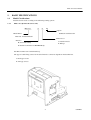
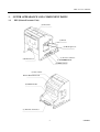
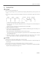
4.1
Connecting the AC Adapter
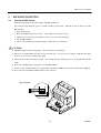
4.1.1
Using the Power Connector
1. Make sure the power switch of the unit is turned off.
2. Connect an optional AC adapter cable connector with the power connector of the unit so that it locks in place.
(As shown in the figure below, the power connector can be mounted at any one of the 6 locations on the unit.)
3. Connect an optional AC power cord to the AC adapter and plug it into an electrical outlet.
12
CITIZEN
PPU-231 User’s Manual
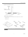
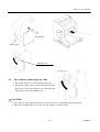
4.1.2
Connecting a Power Cable to the Control PCB
If you wish, you do not need to use an optional AC adapter, instead you can directly connect a power cable
(not supplied) to the control PCB.
1. Turn off the power.
2. Plug the power cable into the CN1 power connector of the control PCB. See the table below for detail
on the CN1 connector pin configurations.
CN1
Power Connector
[Connector’s pin configuration for power supply (CN1)]
No.
1
2
3
4
5
Signal Name
+24V DC
+24V DC
P-GND
P-GND
P-GND
Input/Output
Input
Input
—
—
—
Function
Input Voltage
Input Voltage
GND
GND
GND
Connector used: 5267-05A-X (Molex)
CAUTION:
4)
Use only the specified AC adapter.
5)
When disconnecting/reconnecting the cable connector of the AC adapter, be sure to hold the connector.
6)
Several holes have been prepared on the unit so that the power connector or interface connector can be
easily attached. Never use the same hole for both the power connector and interface connector at the same
time.
4)
Separate the AC adapter from other noise-generating devices.
5)
Pulling the AC power cord may damage it, resulting in a fire, electric shock, or snapping.
13
CITIZEN
PPU-231 User’s Manual
6) If a thunder/lightning storm is nearby, disconnect the AC adapter from the socket and do not use the printer,
because a fire or electric shock may occur.
7)
Do not put the AC power cord close to a heating device. Its coating can melt and cause a fire or electric
shock.
8) Install the printer in a well-ventilated place, because the AC adapter generates heat when it is used.
9) Use the specified AC power source. Connect to a power source with sufficient capacity. If the capacity is
insufficient, a fire may result from heat generation.
10) After using the printer or when not using it for a long period of time, be sure to unplug the AC adapter from
a plug socket for your safety.
4.2
Connecting the Interface Cable
1. Turn off the power. (Mating side included)
2. Check the top and bottom of cable terminals, and connect the cable terminal to the interface connector.
3. Fix the cable terminals.
Serial interface
: Tighten screws, to fix it.
Parallel interface
: Turn stoppers, to fix it.
4. Connect the cable to the host computer.
* This shows how to connect to the rear end of the frame.
14
CITIZEN
PPU-231 User’s Manual
You can attach the interface cable to any one of the 4 positions shown below. See the table below for
details on the CN10 connector pin configurations.
CN10
Interface Connector
[Connector’s pin configurations for parallel interface (CN10)]
No.
1
2
3
4
5
6
7
8
9
10
11
12
13
14
15
16
17
18
19
20
Signal Name
—
—
—
—
STB
BUSY
ACK
DATA0
DATA1
DATA2
DATA3
DATA4
DATA5
DATA6
DATA7
PE
FAULT
RESET
GND
Vcc
Input/Output
—
—
—
—
Output
Output
Output
Input
Input
Input
Input
Input
Input
Input
Input
Output
Output
Input
—
—
Function
—
—
—
—
STB Signal
BUSY Signal
ACK Signal
DATA0 Signal
DATA1 Signal
DATA2 Signal
DATA3 Signal
DATA4 Signal
DATA5 Signal
DATA6 Signal
DATA7 Signal
PE Signal
FAULT Signal
RESET Signal
GND
+5V DC
Connector used: 53313-2015 (Molex)
15
CITIZEN
PPU-231 User’s Manual
[Connector’s pin configuration for serial interface (CN10)]
No.
1
2
3
4
5
6
7
8
9
10
11
12
13
14
15
16
17
18
19
20
Signal Name
DTR
TXD
RXD
DSR
—
—
—
—
—
—
—
—
—
—
—
—
—
—
GND
Vcc
Input/Output
Output
Output
Output
Output
—
—
—
—
—
—
—
—
—
—
—
—
—
—
—
—
Function
DTR Signal
TXD Signal
RXD Signal
DSR Signal
—
—
—
—
—
—
—
—
—
—
—
—
—
—
GND
+5V DC
Connector used: 53313-2015 (Molex)
CAUTION:
1) Referring to "6. PARALLEL INTERFACE" and "7. SERIAL INTERFACE," check the pin configuration of
the interface connector and cable. Wrong wiring could cause trouble or malfunctioning to not only the unit
but also the host computer.
2) When disconnecting/reconnecting the interface cable, be sure to hold the connector. Pulling the cable itself
may snap the internal wires.
3) Connect the interface cable securely. Otherwise, communications may not be obtained due to a connection
failure.
16
CITIZEN
PPU-231 User’s Manual
4.3
Inserting the Paper
CAUTION:
1) Be sure to use the specified paper roll.
2) Use of non-specified paper may not guarantee the print quality, printing head life, presenter operation, and
so on.
3) Do not insert a ragged or dog-eared end of the paper roll, because it could result in a paper jam or insertion
error.
1. Cut the front end of the paper roll almost at a right angle.
2. Insert the paper roller of the paper holding unit into the core of the paper roll as shown in the figure on
the next page.
3. Make sure the paper winding direction and put the paper roll onto the PHU.
4. Make sure that the power is turned on.
5. If there is still some paper remaining after a paper-out indication, eliminate the paper roll according to "4.4
How to Remove the Remaining Paper Roll."
6. Raise the head-up lever of the printer/presenter unit. (See the next page.)
7. Insert the front end of the paper roll straight into a paper insertion slot as shown in the figure on the next
page, until the paper stops.
8. Put back the head-up lever. The paper is automatically pulled in by the platen roller to feed a constant
amount of paper. (When auto-loading is enabled.) Remove the cut paper to enable printing.
CAUTION:
1) If the paper roll is still slack, rewind the paper to remove the slack.
2) If the paper roll is tilted, raise the head-up lever to correct the paper roll position, or pull out the paper roll
and set it again.
3) Do not hold or press the paper roll while printing, because it could cause a paper jam.
4) After the paper is set, the printer is made ready to start printing. Note that if data is remaining in the buffer,
the printer will start printing after the paper is set.
17
CITIZEN
PPU-231 User’s Manual
Paper Roller
(Printer side)
Head-up Lever
Head-up Lever
4.4
How to Remove Remaining Paper Roll
1. Raise the head-up lever of the printer/presenter unit.
2. Gently pull out the paper from the printer/presenter unit.
If the paper roll is still remaining, cut it just before the
paper insertion slot before pulling it out.
CAUTION:
1) Never take out paper with the head-up lever lowered, because it could damage the printing head.
2) The printer mechanism may be very hot just after printing, so be duly careful.
18
CITIZEN
PPU-231 User’s Manual
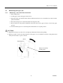
4.5
4.5.1
Eliminating the Paper Jam
Eliminating a Jam in the Printer Mechanism
1. Turn off the power.
2. Cut the paper roll near the paper insertion slot.
3. Move the knobs on both sides in the direction indicated by the arrows to detach the auto cutter from the
printer mechanism.
4. Raise the head-up lever to detach the head from the platen roller.
5. Rotate the knob of the printer mechanism and totally remove the paper roll that is left in the paper
passage.
6. Lower the head-up lever to return the printer mechanism to its original position.
CAUTION:
1) The printer head gets very hot. Do not attempt any maintenance directly after printing.
2) When you wish to remove the unused portion of the paper, do not touch the hot surface of the printer head
with your bare hands or a piece of metal.
Knob
Head-up Lever
Knob (for manually
feeding paper)
19
CITIZEN
PPU-231 User’s Manual
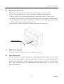
4.5.2
Eliminating a Jam in the Presenter
1. Turn off the power.
2. Open the front door by pulling while pressing on the knob (see the figure).
3. Manually turn the roller until all paper is removed from the paper passage.
4. If a jam occurs between the auto-cutter and the presenter, with tweezers or similar, remove the paper
roll with the utmost care.
5. Firmly close the front door.
CAUTION:
If the presenter rollers do not spin, do not apply extra force as this could break the mechanism.
Rollers
Knob
Front Door
20
CITIZEN
PPU-231 User’s Manual
4.6
Releasing a Locked Cutter
When the auto-cutter locks up and fails to cut paper, follow these steps to solve the problem.
1. Remove the paper from the paper passage as described in "4.5 Eliminating the Paper Jam".
2. Turn on the power. The auto cutter initialization begins and the cutter returns to its home position.
3. If the cutter does not return to its home position after the power has been turned on, do the following.
Turn off the power, and return the auto cutter blade to its home position by turning the emergency knob
of the auto cutter in the direction indicated by the arrow.
4. With tweezers or similar, totally remove remaining paper from the cutter blade area.
Emergency Knob
4.7
FEED Switch Function
Press the feed switch to feed the paper, cut it, and output the cut portion.
4.8
Paper End Function
If the printing paper runs out, the parallel interface will output BUSY, FAULT, and PE to the host, and the
serial interface will output DTR to stop printing, respectively. If some data are still remaining in the buffer,
printing will be resumed after replacing the paper. Replace the paper according to "4.3 Inserting the
Paper." After replacing the paper, cancel BUSY (DTR), FAULT, and PE outputs. For details, see "4.10
Near Paper End Function."
21
CITIZEN
PPU-231 User’s Manual
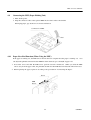
4.9
Connecting the PHU (Paper Holding Unit)
1. Turn off the power.
2. Plug the connector cable of the optional PHU into the CN5 on the control PCB.
When plugging it, pay attention to its insertion direction.
Connector for PHU
CN5
4.10
Paper Near End Function (When Using the PHU)
If the paper is running out, the PNE sensor informs the host computer that the paper is running out. You
can adjust the printable amount left after PNE has been detected, up to aboutφ50 of paper roll.
1. Loosen the screw and slide the PNE sensor position forward or backward. When you slide the PNE
sensor away from the paper roller, the printable amount left after PNE has been detected will be increased.
2. When replacing the paper, replace it according to the procedure in "4.3 Inserting the Paper."
Screw
PNE
Sensor
22
CITIZEN
PPU-231 User’s Manual
4.11
Auto-Loading Function
This printer has a function to automatically set the paper. When the paper is set and the paper end sensor
and paper near end sensor are not detected, and the head-up lever is lowered, the paper will be automatically
fed by a constant amount in about 1 second.
If the paper is not automatically fed, remove the paper from the paper insertion slot and try again.
You can use the DIP switch to enable/disable the function. If disabled, auto-loading will not be performed.
CAUTION:
1) When auto-loading is being activated, do not touch the paper roll, because it could result in a paper feed
failure or cause the paper to be one-sided.
2) Be sure to set the paper until it comes into contact with the platen roller; otherwise, the paper cannot be fed
and the printing head could be damaged.
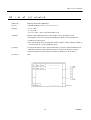
4.12
Self-Print Function
This unit has a function to perform preset printing. Turn on the power with the FEED switch held down.
It will print the ROM version, DIP switch state, characters used, etc.
CAUTION:
Do not use this function when the paper roll is running out.
4.13
Presenter Control
This unit feeds in paper while printing or transporting paper.
After having operated the auto cutter, the unit delivers out the paper.
The next printing operation does not start until the paper ejected is removed.
(Printing is holted.)
CAUTION:
Do not approach your face or hand toward the Presenter’s paper output slot while the paper is being output.
23
CITIZEN
PPU-231 User’s Manual
5.
5.1
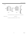
DIP SWITCH SETTING
Location of DIP Switch
The following figure clearly shows where the DIP switches are.
Any settings made while the power is turned on will not take effect. Turn the power on after you set the
DIP switches.
1. Turn off the power.
2. Remove the DIP switch cover screw.
(Be careful not to lose the screw.)
3. Slide the cover towards you and lift it to remove (see arrows in the figure).
4. Set the DIP switches.
5. After you have made the required settings, reattach the cover and screw.
CAUTION:
1) The DIP switch cover has sharp edges. Be careful not cut your fingers.
2) The screw is an M 2x3mm type. Do not use any other type. If you do lose it, replace it with the same type.
Do not use screws that are longer than 3mm.
3) Always turn off the power before setting. If you make settings while the power is on, the unit may become
faulty.
4) Do not use anything sharp and pointy to set the DIP switches.
5) Always set the switches that have been specified as disabled to OFF (the setting that existed when shipped).
6) Do not use the unit while the DIP switch cover is removed.
Dip Switches
24
CITIZEN
PPU-231 User’s Manual
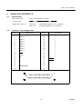
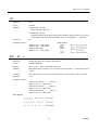
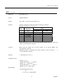
5.2
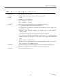
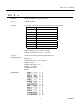
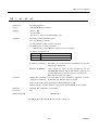
DIP Switch Function
DIP switch 1 (DS1)
No.
DS1- 1
2
Function
Auto cutter
CR switching
3
Printing density
4
DTR-DSR/XON-XOFF
5
Baud rate and parity setting
6
Baud rate and parity setting
7
Baud rate and parity setting
8
Baud rate and parity setting
ON
Enabled
LF operation
OFF
Disabled
Ignored
Upon Shipment
ON
OFF
Combination with DS2-6.
See Table 2.
XON−XOFF
OFF
OFF
DTR−DSR
OFF
OFF
See Table 1.
OFF
OFF
DIP switch 2 (DS2)
No.
1
2
3
4
5
Function
PNE function
Reserved
Reserved
Auto-loading
Paper selection
6
Print density
ON
Enabled
OFF
Disabled
Upon Shipment
ON•
ON
ON
ON
ON
Enabled
Normal thermal
paper
Disabled
Dedicated
thermal paper
(Black mark)
Combination with DS1-3.
See Table 2.
8 Bits
7 Bits
ON
7
Data length
ON
8
Not used
ON
* With the type U model (North American type), the DIP switches marked are set to OFF.
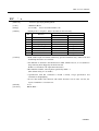
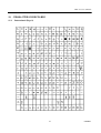
Table 1
Baud rate and parity setting
DS1-8
DS1-7
DS1-6
DS1-5
Interface
OFF
OFF
OFF
OFF
Parallel input
—
—
OFF
OFF
OFF
OFF
OFF
OFF
OFF
OFF
ON
ON
OFF
ON
ON
OFF
OFF
ON
OFF
ON
OFF
ON
Serial input
″
″
″
″
1,200 bps
2,400 bps
4,800 bps
9,600 bps
19,200 bps
OFF
OFF
ON
ON
ON
ON
ON
OFF
OFF
OFF
ON
ON
OFF
OFF
ON
OFF
ON
OFF
ON
OFF
″
″
″
″
″
ON
ON
ON
ON
ON
OFF
ON
ON
ON
ON
ON
OFF
OFF
ON
ON
ON
OFF
ON
OFF
ON
″
″
″
″
″
None
″
″
″
″
Odd
″
″
″
″
Even
″
″
″
″
25
Parity
Baud Rate
1,200 bps
2,400 bps
4,800 bps
9,600 bps
19,200 bps
1,200 bps
2,400 bps
4,800 bps
9,600 bps
19,200 bps
CITIZEN
PPU-231 User’s Manual
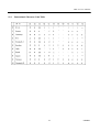
Table 2
Print density
DS1-3
DS2-6
Print Density
Level
OFF
OFF
ON
ON
OFF
ON
OFF
ON
Light
Standard
Dark
Darker
0
1
2
3
26
CITIZEN
PPU-231 User’s Manual
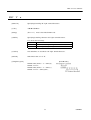
6.
6.1
PARALLEL INTERFACE
Specifications
• Data input system
: 8-bit parallel (DATA0 to DATA7)
• Control signals
: ACK, BUSY, STROBE, FAULT, PE, RESET
• Applicable connectors
: Printer side
Cable side
6.2
: 57LE-40360 (Anphenol) or its equivalent
: 57-30360 (Anphenol) or its equivalent
Connector's Pin Configuration
No.
1
2
3
4
5
6
7
8
9
10
11
12
13
14
15
16
17
18
Signal Name
STROBE
DATA 0
DATA 1
DATA 2
DATA 3
DATA 4
DATA 5
DATA 6
DATA 7
ACK
BUSY
PE
FRAME GND
27
No.
Signal Name
19
20
21
22
23
24
25
26
27
28
29
30
31
32
33
34
35
36
TWISTED PAIR GND
↑
↑
↑
↑
↑
↑
↑
↑
↑
↑
↑
RESET
FAULT
CITIZEN
PPU-231 User’s Manual
6.3
Input and Output Signals
6.3.1
Input and Output Signals
(1) Input signals to the printer
• DATA
: 8-bit parallel signal (Active: “High”)
• STROBE
: Strobe signal to read the 8-bit data (Active: “Low”)
• RESET
: Signal to reset the entire printer (Active: “Low”); 1 ms or more
(2) Output signals from the printer
• ACK
: 8-bit data request signal.
A pulse signal to be output at the end of the BUSY signal
(Active: “Low”)
• BUSY
: Signal to indicate that the printer is busy.
Input new data when it is "Low."
(Active: “High”)
• FAULT
: Turned to "Low" when the printer has an alarm. At this time, all the control circuits in
the printer stop. (Active: “Low”)
• PE
: Output if the printing paper has run out or is running out. (Active: “High”)
28
CITIZEN
PPU-231 User’s Manual
6.3.2
Electrical Characteristics
(1) Input signal level
All the input signals are at the TTL level.
High level --- 2.0 V at minimum
Low level --- 0.8 V at maximum
(2) Output signal level
All the output signals are at the TTL level.
High level --- 2.4 V at minimum
Low level --- 0.4 V at maximum
(3) Input and output conditions
The STROBE and RESET input signals are pulled up at 3.3kΩ, and the other input signals at 50kΩ,
respectively.
[Printer Side]
[Host Side]
All the output signals are pulled up at 50kΩ.
[Printer Side]
[Host Side]
29
CITIZEN
PPU-231 User’s Manual
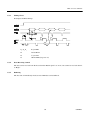
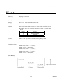
6.3.3
Timing Chart
Data Input and Print Timings
6.3.4
T1, T2, T3
0.5 µs MIN
T4
270 ns MAX
T5
2.3 µs TYP
T6
500 ms MIN (At power-on)
Data Receiving Control
The data can be received from the host when the BUSY signal is at "Low," but cannot be received when it
is "High."
6.3.5
Buffering
The host side is immediately freed, because 4 KB data can be buffered.
30
CITIZEN
PPU-231 User’s Manual
7.
7.1
SERIAL INTERFACE
Specifications
(1) Synchronous system
: Asynchronous
(2) Baud rate
: 1,200, 2,400, 4,800, 9,600, 19,200 bps (Selected by the user)
(3) 1-word configuration
Start bits
: 1 bit
Data bits
: 8 bits or 7 bits (Setting upon shipment)
Parity bits
: Odd, even, or no parity (Selected by the user)
Stop bits
: 1 bit or more
(4) Signal polarity
RS-232C
• Mark
= Logic "1" (-3 ∼ -12 V)
• Space
= Logic "0" (+3 ∼ +12 V)
(5) Received data (RXD signal)
• Mark
= 1
• Space
= 0
(6) Reception control (DTR signal)
• Mark
:
Data not transferable
• Space
:
Data transferable
(7) Transmission control (TXD signal)
7.2
• DC1 code(11H) X-ON
:
Data receivable
• DC3 code(13H) X-OFF
:
Data not receivable
Connector's Pin Configuration
No.
1
7
3
20
2
6
Signal Name
FG
GND
RXD
DTR
TXD
DSR
Input/Output
Function
Frame Ground
Signal Ground
Received Data
Printer BUSY Signal
Transmitted Data
Data Set Ready
Input
Output
Output
Input
[Note] 1. The RS-232C signals are based on the EIA RS-232C.
2. The received data should be always maintained in the Mark status when no data is being
transferred.
Applicable connectors (D-Sub connectors)
Printer side : 17LE-13250 (Anphenol) or its equivalent
Cable side
: 17JE-23250 (Anphenol) or its equivalent
31
CITIZEN
PPU-231 User’s Manual
7.3
Input and Output Signals
7.3.1
Input and Output Signals
(1) RXD
Serial received data signal. If a framing error, overrun error, or parity error takes place, the relevant
data will be printed as "?".
(2) DTR
Write the data or a command when this signal is Ready.
If you write at Busy, the previous data will be
ignored, resulting in an overrun error. The data can be written in the input buffer even during printing.
Busy is also issued at power-on, during test printing, at on-line, or at reset.
(3) TXD
If the remaining capacity of the input buffer comes to 128 bytes or less while receiving the data,
DC3(13H) will be output as a data not receivable signal. If the remaining capacity comes to 256 bytes
or more, DC1(11H) will be output to the host side as a data receivable signal.
When sending the status information, it is confirmed that DSR is a space prior to sending the data, if
DTR/DSR control has been selected. If DTR/DSR control has not been selected, the data will be sent,
ignoring the DSR signal.
(4) FG
Ground for the case
(5) GND
Common ground for the circuits
32
CITIZEN
PPU-231 User’s Manual
7.3.2
Data Configuration
t
Mark
b0, b1, b2, • • • •
Space
(1)
(2)
(3)
(1) Start Bit
(2) Data Bit (+ Parity Bit)
(3) Stop Bit (1 or More)
(1) Start bit
The system reads the status again after a lapse of 1/2 bit from a fall edge from the mark to space, and if it
is a space, this bit will be recognized as the start bit.
If it is a mark, the system will not recognize the bit as the start bit and try to detect the start bit again
without judging it as an error.
(2) Data bits + Parity bit
The system samples the data bits and parity bit for the 1 bit worth of time from 1/2 start bit and assumes
the then status as the data for the relevant bits. The bits are called Bit 0, Bit 1, ..., Parity bit, counting
from the one closest to the start bit.
(3) Stop bit
The stop bit is the Mark level of 1 bit or more. If a space is detected in detecting the stop bit, a framing
error will result.
7.3.3
Error Detection
The system detects a parity, framing, or overrun error. If an error is detected, the relevant data will be
stored in the buffer as "?".
(1) Parity error
With a parity check specified, if an error is detected at parity check time, the relevant data will be
stored in the buffer as "?".
(2) Framing error
This error results if the Space status is detected at stop bit detection time. The relevant data will be
stored in the buffer as "?".
(3) Overrun error
If an overrun error is detected, the relevant data will be stored in the buffer as "?".
33
CITIZEN
PPU-231 User’s Manual
7.3.4
Data Receiving Control
If DTR/DSR control has been selected, the data from the host side will be received when the BUSY signal
is at "Low," but not received when at "High." If DTR/DSR has not been selected, the data from the host
side will be received after sending XON, but not after sending XOFF.
7.3.5
Buffering
To transfer the data to the input buffer, there are two control signals available: DTR signal and TXD
signal. The host side is immediately freed, since the data can be buffered up to 4 KB.
(1) DTR signal (See 7.3.1-(2))
(2) TXD signal (See 7.3.1-(3))
7.3.6
Electrical Characteristics
RS-232C Circuit
Input (RXD, DSR)
[Printer Side]
[Host Side]
Mark=(-8V): Stop bit
RXD
Space=(+8V): Start bit
Equivalent to MAX232
Output (TXD, DTR)
[Printer Side]
[Host Side]
Equivalent to MAX232
Mark=(-8V): At Busy
DTR
Mark=(-8V): 1
TXD
Space=(+8V): At Busy
34
Space=(+8V): 0
CITIZEN
PPU-231 User’s Manual
8.
POWER CONNECTOR
This connector is to supply the power from the special AC adapter (31AD).
Connector's Pin Configurations
No.
Function
1
2
+24V
GND
3
SHELL
N.C
FG
Connector used
: TSC7960-53-2010 (Made by HOSHIDEN) or its equivalent
Applicable connector
: TSC8927-63-1100 (Made by HOSHIDEN) or its equivalent
TSC8927-53-1100 (Made by HOSHIDEN) or its equivalent
CAUTION:
1) Be sure to use the specified AC adapter. Use of any other power source could cause trouble to or break the
printer.
2) Do not connect the power source with different polarity.
3) After using the printer or when not using it for a long period of time, be sure to unplug the AC adapter from
a plug socket for your safety.
35
CITIZEN
PPU-231 User’s Manual
9.
MAINTENANCE AND SERVICE
For the information on maintenance and service, please contact our dealer.
36
CITIZEN
PPU-231 User’s Manual
10. PRINT CONTROL FUNCTIONS
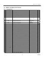
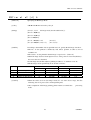
10.1
Commands List
Control Code
1
2
3
4
5
6
7
HT
LF
CR
ESC SP
ESC !
ESC %
ESC &
Function
Horizontal tab
Printing and paper feed
Print
Setting the right space amount of the character
Collective specifying printing mode
Specifying/canceling download character set
Defining download characters
8
ESC
∗
Specifying the bit image mode
9
10
11
12
13
14
15
16
17
18
19
20
21
22
23
24
25
26
27
28
29
30
31
32
33
34
35
36
37
38
ESC
ESC
ESC
ESC
ESC
ESC
ESC
ESC
ESC
ESC
ESC
ESC
ESC
ESC
ESC
ESC
ESC
ESC
ESC
ESC
ESC
ESC
ESC
ESC
ESC
GS
GS
GS
GS
GS
−
2
3
=
@
D
E
G
J
R
V
a
c3
c4
c5
d
i
m
p
t
u
v
{
$
5
S
k
w
h
H
Specifying/canceling underline
Specifying 1/6-inch line feed rate
Setting line feed rate of minimum pitch
Data input control
Initializing the Printer
Setting horizontal tab position
Specifying/canceling highlighting
Specifying/canceling double printing
Printing and feeding paper n/203 inch
Selecting the international character set
Specifying/Canceling 90°-right- turned Characters
Aligning the characters
Selecting the paper near end sensor valid for a paper end
Selecting the paper near end sensor valid for print stop
Enabling/disabling the panel switches
Printing and feeding the paper by n lines
Activating auto cutter
Activating auto cutter
Code
09H
0AH
0DH
1BH 20H n
1BH 21H n
1BH 25H n
1BH 26H s n m
[a p1 p2 ... ps×a]
m-n+1
1BH 2AH m n1
n2 [d]k
1BH 2DH n
1BH 32H
1BH 33H n
1BH 3DH n
1BH 40H
1BH 44H [n]k 00H
1BH 45H n
1BH 47H n
1BH 4AH n
1BH 52H n
1BH 56H n
1BH 61H n
1BH 63H 33H n
1BH 63H 34H n
1BH 63H 35H n
1BH 64H n
1BH 69H
1BH 6DH
Page
40
40
41
41
42
44
45
47
49
49
50
51
52
53
54
55
55
56
57
58
59
59
60
60
61
62
NOP
Selecting the character code table
1BH 74H n
63
1BH 76H n
1BH 7BH n
1BH 24H n1 n2
1BH 5C n1 n2
1DH 53H
1DH 6BH n [“d”]k 00H
1DH 77H n
1DH 68H n
1DH 48H n
64
65
66
67
67
68
72
73
74
NOP
Transmitting the printer status (Serial type)
Specifying/canceling the inverted characters
Specifying the absolute positions
Specifying the relative positions
Detection of black mark (M model)
Printing the bar code
Selecting the horizontal size (scale factor) of bar code
Selecting the height of the bar code
Selecting of print position of HRI code
37
CITIZEN
PPU-231 User’s Manual
Control Code
39
GS
f
40
GS
41
42
43
GS
GS
GS
Function
Code
Selecting the font of HRI code
1DH 66H n
∗
Defining the download, bit image
/
:
^
Printing the download, bit image
1DH 2AH n1 n2 [d] n1
×n2×8
1DH 2FH m
1DH 3AH
1DH 5EH n1 n2 n3
Starting/ending macro definition
Executing the macro
Page
75
76
78
79
80
Notes 1. n, n1, n2, n3, n4, n5, n6, m, a, s, p, d, N1, N2, N3,N4, and N5 in the table are parameters for
each commands.
2. [ ]k in the table denotes k-times of repeat.
3. Characters shown in “ ” are the ASCII characters.
38
CITIZEN
PPU-231 User’s Manual
10.2
10.2.1
Command Details
Description of Items
XXXX
ALL
[Function]
Command Function
[Code]
A sequence of code constituting a command is represented in hexadecimal number for <
>H, binary number for <
>B, and decimal number for <
>, respectively; [
]k
represents a repeat count of k-times.
[Range]
Describes an argument value (Setting range) for the command.
[Outline]
Describes a command outline.
[Caution]
Describes a caution as required.
[Default]
Describes an initial value for the command when accompanied by an argument.
[See Also]
Describes the associated commands for use.
[Sample Program]
Describes a coding example in the Q-BASIC sample program.
This example is only for your reference and differs depending on the language used,
version, and so on. For details, see the manual for the language used.
39
CITIZEN
PPU-231 User’s Manual
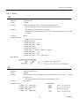
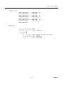
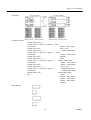
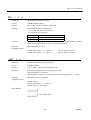
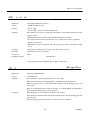
10.2.2
Details
HT
[Function]
Horizontal Tab
[Code]
<09>H
[Outline]
Shifts the printing position to the next horizontal tab position.
• Ignored when the next horizontal tab position has not been set.
• The horizontal tab position is set by ESC D.
[Caution]
• Initial setting of the horizontal tab position is each 8 characters in 9th, 17th, 25th,
columns.
[See Also]
ESC D
[Sample Program]
LPRINT "0123456789012345678901" ;
LPRINT CHR$ (&HA) ;
LPRINT CHR$ (&H9) + "AAA" ;
LPRINT CHR$ (&H9) + "BBB" ;
LPRINT CHR$ (&HA);
LPRINT CHR$ (&H1B) + "D" ;
LPRINT CHR$ (3) + CHR$ (7) + CHR$ (14) + CHR$ (0) ;
LPRINT CHR$ (&H9) + "AAA" ;
LPRINT CHR$ (&H9) + "BBB" ;
LPRINT CHR$ (&H9) + "CCC" + CHR$ (&HA) ;
[Print Results]
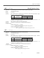
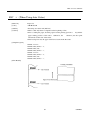
LF
[Function]
Printing and Paper Feed
[Code]
<0A>H
[Outline]
Prints data inside the input buffer and feeds lines based on the line feed
having been set.
amount
• The head of the line becomes the next print starting position.
[See Also]
ESC 2, ESC 3
[Sample Program]
[Print Results]
LPRINT "AAA" + CHR$ (&HA) ;
LPRINT "BBB" + CHR$ (&HA) ;
LPRINT CHR$ (&HA) ;
LPRINT "CCC" + CHR$ (&HA) ;
40
CITIZEN
PPU-231 User’s Manual
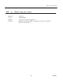
CR
[Function]
Print
[Code]
<0D>H
[Outline]
1) When DS1-2 is OFF:
This command is ignored.
2) When DS1-2 is ON:
With data held inside the internal print buffer, printing and line feed are performed.
Without data inside the internal print buffer, however, no printing is performed.
LF
[See Also]
[Sample Program]
[Print Results]
LPRINT "AAA" + CHR$ (&HD) ;
LPRINT "BBB" + CHR$ (&HD) ;
LPRINT CHR$ (&HD) ;
LPRINT "CCC" + CHR$ (&HD) ;
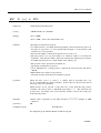
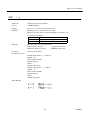
ESC
SP
n
[Function]
Setting the right space amount of the character
[Code]
<1B>H<20>H<n>
[Range]
{0 ≤ n ≤ 20}
[Outline]
The rightward space amount is set in dot unit (1/203 inch unit). In the initial value, it
is n=0.
[Caution]
The rightward space amount in double wide mode is made double of the set volume.
[Default]
n=0
Data is described in Hex code.
[Sample Program]
LPRINT CHR$ (&H1B) + "
" + CHR$ (0) ;
LPRINT "AAAAA" + CHR$ (&HA) ;
LPRINT CHR$ (&H1B) + "
" + CHR$ (1) ;
LPRINT "AAAAA" + CHR$ (&HA) ;
LPRINT CHR$ (&H1B) + "
" + CHR$ (12) ;
LPRINT "AAAAA" + CHR$ (&HA) ;
[Print Results]
41
CITIZEN
PPU-231 User’s Manual
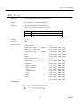
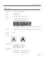
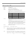
ESC
! n
[Function]
Collective Specifying Printing Mode
[Code]
<1B>H<21>H<n>
[Range]
{0 ≤ n ≤ FF}
[Outline]
Printing mode is assigned. Each n bit indicates the following:
[Caution]
Data is described in Hex code.
Bit
Function
0
1
2
3
4
5
6
7
Character Font
Undefined
Undefined
High-lighting
Double height
Double width
Undefined
Underline
Value
0
Font A
1
Font B
Canceled
Canceled
Canceled
Specified
Specified
Specified
Canceled
Specified
• With double height and double width being specified simultaneously, double wide and
double high characters are consisted.
• An underline is attached to the full character width, which, however, is not attached to
the part having been skipped by the horizontal tab.
Neither is it attached to 90°-right-turned characters.
• The underline width is as having been specified by <ESC - >.
(The default setting is 1 dot width. )
• Specification with this command is invalid to Kanji, except specification and
cancellation of highlighting
• In case that double wide character and normal character exist in same one line, the
layout of underline is consistent one.
[Default]
n=0
[See Also]
ESC E, ESC −
42
CITIZEN
PPU-231 User’s Manual
[Sample Program]
LPRINT CHR$ (&H1B) + " ! " + CHR$ (&H00) + "H" ;
LPRINT CHR$ (&H1B) + " ! " + CHR$ (&H01) + "H";
LPRINT CHR$ (&H1B) + " ! " + CHR$ (&H08) + "H";
LPRINT CHR$ (&H1B) + " ! " + CHR$ (&H10) + "H";
LPRINT CHR$ (&H1B) + " ! " + CHR$ (&H20) + "H";
LPRINT CHR$ (&H1B) + " ! " + CHR$ (&H80) + "H";
LPRINT CHR$ (&H1B) + " ! " + CHR$ (&HB9) + "H";
LPRINT CHR$ (&HA) ;
[Print Results]
43
CITIZEN
PPU-231 User’s Manual
ESC
%
n
[Function]
Specifying/Canceling Download Character Set
[Code]
<1B>H<25>H<n>
[Range]
[Outline]
{0 ≤ n ≤ FF} data is described in Hex code.
Specifying/canceling download characters.
Further, only the lowest bit (n0) is valid for n.
The lowest bit (n0) indicates the following.
n0
0
1
[Caution]
Function
Canceling download character set
Specifying download character set
Download characters and download bit images can not be defined simultaneously.
[Default]
n=0
[See Also]
ESC &
[Sample Program]
GOSUB SETCHR
DATA
6
LPRINT CHR$ (&H1B) + "%" + CHR$ (0) ;
DATA
&HFF, &H80, &H00
LPRINT "@A" + CHR$ (&HA) ;
DATA
&H80, &H80, &H00
LPRINT CHR$ (&H1B) + "%" + CHR$ (1) ;
DATA
&H80, &H80, &H00
LPRINT "@A" + CHR$ (&HA) ;
DATA
&H80, &H80, &H00
END
DATA
&HFF, &HFF, &HFF
SETCHR :
DATA
&HFF, &HFF, &HFF
LPRINT CHR$ (&H1B) + "&" ;
DATA
12
LPRINT CHR$ (3) + "@" + "A" ;
DATA
&HFF, &HFF, &HFF
FOR J=1 TO 2
DATA
&H80, &H07, &HF9
READ REP
DATA
&H80, &HFF, &HF9
LPRINT CHR$ (REP) ;
DATA
&H87, &HFE, &H01
FOR I=1 TO REP∗3
DATA
&H9F, &H06, &H01
READ D
DATA
&HF8, &H06, &H01
LPRINTCHR$ (D) ;
DATA
&HF8, &H06, &H01
DATA
&H9F, &H06, &H01
DATA
&H87, &HFE, &H01
NEXT I
NEXT J
RETURN
DATA
&H80, &HFF, &HF9
DATA
&H80, &H07, &HF9
DATA
&HFF, &HFF, &HFF
[Print Results]
44
CITIZEN
PPU-231 User’s Manual
ESC
& s n
m [ a [ p ] s × a] m – n +1
[Function]
Defining Download Character
[Code]
<1B>H<26>H<s><n><m> [<a><p1><p2>••<ps×a>]m-n+1
[Range]
{s = 03}
{20 (Hex) ≤ n ≤ m ≤ 7E (Hex)}
{0 ≤ a ≤ 0C(Hex)} (Font A)
{0 ≤ a ≤ 0A(Hex)} (Font B)
[Outline]
Defines the font of download characters of alphanumeric characters.
• "s" indicates the number of bytes in vertical direction.
• "n" indicates the start character code and m the end character code. To define only
one character, set n=m.
• Character codes definable includes 95 ASCII codes in
<20>H∼<7E>H.
total between
• "a" indicates the number of dots in horizontal direction for definition.
• "p" is the data to be defined, which indicate a pattern equal to "a" dot in horizontal
direction from the left end. The rest of the pattern on the right side is filled with
space.
The rest of data to be defined is s x a.
• Download characters thus defined remain valid until redefinition, ESC @ execution,
GS * execution, or power OFF is practiced.
[Caution]
Download characters and download bit images can not be defined simultaneously.
Running this command clears the definition of the download bit image.
[Default]
Same as the internal character set
45
CITIZEN
PPU-231 User’s Manual
[Example]
Create each data bit by setting "1" for a printed dot and "0" for an unprinted dot.
[Sample Program]
[Print Results]
See Sample Program and Print Results for ESC % on Page 44.
46
CITIZEN
PPU-231 User’s Manual
ESC ∗ m n1 n2 [ d ] k
[Function]
Specifying the Bit Image Mode
[Code]
<1B>H<2A>H<m><n1><n2> [ <d> ] k
[Range]
{m= 0, 1, 32, 33
bit image mode (See the table below.)}
{0 ≤ n1 ≤ FF(Hex)}
{0 ≤ n2 ≤ 03(Hex)}
{0 ≤ d ≤ FF(Hex)}
[Outline]
{k = n1 + FF(Hex) × n2
(m = 0, 1)
{k = (n1+ FF(Hex) × n2) × 3}
(m = 32, 33)
According to the number of dots specified in n1, n2, specify the bit image of mode n.
• The No. of dots printed is divided by 256, whose quotient is taken as n2 nd
residualas n1.
• The total no. of dots printed in the bit image is equal to n1 + (256 x n2).
• When bit image data have been input in excess of dot position of one line(448 dots) ,
the excess data are discarded.
• d is bit image data, the bits subject to printing are taken as "1" and those not as "0".
• The bit image modes specified by m are shown as follows:
m(Hex)
Mode
0
1
20
21
8-dots single density
8-dots double density
24-dots single density
24-dots double density
[Caution]
Vertical Direction
No. of Dots
Dot Density
8
67 DPI
8
67 DPI
24
203 DPI
24
203 DPI
Horizontal Direction
Dot Density
Max. No. of Dots
101 DPI
288
203 DPI
576
101 DPI
288
203 DPI
576
• When the values set in m (bit image mode) are out of the above range, the data
following after n1 is processed as normal printing data.
• After completion of bit image printing, printer returns to normal data
mode.
47
processing
CITIZEN
PPU-231 User’s Manual
[Example]
[Sample Program]
LPRINT CHR$ (&H1B) + "∗" ;
LPRINT CHR$ (0) + CHR$ (20) + CHR$ (0) ;
IMG1 :
GOSUB IMG1
LPRINT
LPRINT CHR$ (&HA) ;
FOR I=1 TO 18
LPRINT CHR$ (&H1B) + "∗" ;
LPRINT CHR$ (1) + CHR$ (20) + CHR$ (0) ;
GOSUB IMG1
LPRINT CHR$ (&H85) ;
NEXT I
LPRINT
LPRINT CHR$ (&HA) ;
CHR$ (&HFF) ;
CHR$ (&HFF) ;
RETURN
LPRINT CHR$ (&H1B) + "∗" ;
LPRINT CHR$ (32) + CHR$ (20) + CHR$ (0) ;
IMG2 ;
LPRINT
CHR$ (&HFF) ;
GOSUB IMG2
LPRINT
CHR$ (&HFF) ;
LPRINT CHR$ (&HA) ;
LPRINT
CHR$ (&HFF) ;
LPRINT CHR$ (&H1B) + "∗" ;
FOR I=1 TO 18
LPRINT CHR$ (33) + CHR$ (20) + CHR$ (0) ;
GOSUB IMG2
LPRINTCHR$ (&H80) ;
LPRINTCHR$ (&H00) ;
LPRINT CHR& (&HA) ;
LPRINTCHR$ (&H05) ;
END
NEXT I
LPRINT
CHR$ (&HFF) ;
LPRINT
CHR$ (&HFF) ;
LPRINT
CHR$ (&HFF) ;
RETURN
[Print Results]
48
CITIZEN
PPU-231 User’s Manual
ESC − n
[Function]
Specifying/Canceling Underline
[Code]
<1B>H<2D>H<n>
[Range]
{0 ≤ n ≤ 02} data is described in Hex code.
[Outline]
Specifying/canceling an underline.
•Types of underlines by n value are shown below:
n (Hex)
0
1
2
[Caution]
Type
Canceling an underline.
Specifying an underline for 1-dot width.
Specifying an underline for 2-dots width.
• An underline is attached to the full character width. It is, however, not attached to
the part having been skipped by horizontal tab command.
• An underline is not attached to a 90 °- right-turned characters.
• Specification/cancellation with this command is invalid to Kanji.
[See Also]
ESC !, FS −
[Sample Program]
LPRINT CHR$ (&H1B) + "−" + CHR$ (0) ;
LPRINT "AAAAA" ;
LPRINT CHR$ (&H1B) + "−" + CHR$ (1) ;
LPRINT "AAAAA" + CHR$ (&HA) ;
[Print Results]
ESC
2
[Function]
Specifying 1/6-inch Line Feed Rate
[Code]
<1B>H<32>H
[Outline]
The line feed rate per line is specified by 1/6 inch.
[Sample Program]
[Print Results]
LPRINT "AAAAA" + CHR$ (&HA) ;
LPRINT CHR$ (&H1B) + "3" + CHR$ (0) ;
LPRINT "AAAAA" + CHR$ (&HA) ;
LPRINT CHR$ (&H1B) + "3" + CHR$ (50) ;
LPRINT "AAAAA" + CHR$ (&HA) ;
LPRINT CHR$ (&H1B) + "2" ;
LPRINT "AAAAA" + CHR$ (&HA) ;
LPRINT "AAAAA" ;
LPRINT CHR$ (&H1B) + "J" + CHR$ (100) ;
LPRINT "AAAAA" + CHR$ (&HA) ;
LPRINT "AAAAA" + CHR$ (&HA) ;
49
CITIZEN
PPU-231 User’s Manual
ESC
3 n
[Function]
Setting Line Feed Rate of Minimum Pitch
[Code]
<1B>H<33>H<n>
[Range]
{0 ≤ n ≤ FF} Data is described in Hex code.
[Outline]
The line feed rate per line is specified by n/360 inch.
Since an actual mechanical pitch is 1/203 inch, it is internally converted
approximate to the value specified with this command.
[Default]
• The initial value is n = 60 (1/6 inch) (18H), being 4.23 mm line feed rate.
[Sample Program]
[Print Results]
See Sample Program and Print Results for ESC 2 on Page 49.
50
CITIZEN
PPU-231 User’s Manual
ESC = n
[Function]
Data Input Control
[Code]
<1B>H<3D>H<n>
[Range]
{0 ≤ n ≤FF} Data is described in Hex code.
[Outline]
Selecting equipment in which data input from the host is effective.
• Each bit of n indicates as follows:
Bit
Equipment
0
1
2
3
4
5
6
7
Printer
Not defined
Not defined
Not defined
Not defined
Not defined
Not defined
Not defined
Value
0
Invalid
1
Valid
• When the printer has not been selected, this printer abandons all the received data
until it is selected by this command.
[Caution]
• Even when the printer has not been selected, it can become BUSY state
through printer operation.
• When the printer is deselected, this printer discards all the data until it
selected with this command.
[Default]
•
is
The initial value of n is "1".
[Sample Program]
LPRINT "AAAAA" ;
LPRINT CHR$ (&H1B) + "=" + CHR$ (0) ;
LPRINT "aaaaa" + CHR$ (&HA) ;
LPRINT CHR$ (&H1B) + "=" + CHR$ (1) ;
LPRINT "AAAAA" + CHR$ (&HA) ;
[Print Results]
51
CITIZEN
PPU-231 User’s Manual
ESC
@
[Function]
Initializing the Printer
[Code]
<1B>H<40>H
[Range]
Clears data stored in the print buffer and brings various settings to the initial state
(Default state).
[Caution]
• Data inside the internal input buffer are not cleared.
• Dip switches setting are red once again.
[Sample Program]
LPRINT CHR$ (&H1B) + " ! " + CHR$ (&H30) ;
LPRINT CHR$ (&H1B) + "V" + CHR$ (1) ;
LPRINT "AAA" + CHR$ (&HA) ;
LPRINT CHR$ (&H1B) + "@" ;
LPRINT "AAA" + CHR$ (&HA) ;
[Print Results]
← Each setting are initialized by reset command.
52
CITIZEN
PPU-231 User’s Manual
ESC
D [ n ] k NUL
[Function]
Setting Horizontal Tab Position
[Code]
<1B>H<44>H [ <n> ] k<00>H
[Range]
{0 ≤ n ≤ FFH}
{0 ≤ k ≤ 20H} Data is described in Hex code.
[Outline]
Specifying a horizontal tab position.
• "n" indicates the no. of columns from the beginning to the horizontal tab position. At
this time, n= set position− 1 is to be specified. For example, to set the position at 9th
column, n=8 is to be specified.
• k denotes the number of horizontal tab positions you want to set.
• The tab position is set at position where it is "character width x n" from the line
beginning. The character width, at this time, includes the rightward space amount.
In double wide characters, it is made double of the ordinary case.
• Tab positions can be specified are maximum 32.
Specifying exceeding this is ignored.
• <n> k, which denotes a setting position, is input in the increasing order and ends at
<00> H.
• ESC D NUL clears all the set tab positions.
Following clearing, horizontal tab command is ignored.
[Caution]
When the data, <n> k, is equal to or smaller than its preceding data, <n>
k-1, it is assumed that tab setting is finished. If this is the case, the next data onward
will be processed as normal data.
When the data, <n> k, exceeds a 1-line print area, set the horizontal tab position,
assuming "Set digit position = Maximum print digits + 1." The horizontal tab
position does not change even if the character width is altered after setting the
horizontal tab position.
[Default]
• Initial value is specified for each eight characters (9th.17th.25th columns) of ANK
characters.
[See Also]
HT
[Sample Program]
[Print Results]
See Sample Program and Print Results for HT on Page 40.
53
CITIZEN
PPU-231 User’s Manual
ESC
E n
[Function]
Specifying/canceling highlighting
[Code]
<1B>H<45>H<n>
[Range]
{0 ≤ n ≤ FF} Data is described in Hex code.
[Outline]
Specifying/canceling the highlighting characters.
• "n" is valid only for the lowest bit (n0).
• Control by the lowest bit (n0) is shown as follows:
n0
0
1
Type
Canceling highlighting.
Specifying highlighting.
• This is effective to all characters.
• Dot configuration of a highlighted character includes one extra dot added at its side.
[Caution]
[See Also]
• The print result of Double printing and highlight character printing is completely
same.
ESC !
[Example]
[Sample Program]
LPRINT CHR$ (&H1B) + "E" + CHR$ (0) ;
LPRINT "AAABBB" + CHR$ (&HA) ;
LPRINT CHR$ (&H1B) + "E" + CHR$ (1) ;
LPRINT "AAABBB" + CHR$ (&HA) ;
[Print Results]
54
CITIZEN
PPU-231 User’s Manual
ESC
G n
[Function]
Specifying/canceling Double Printing (ESC G n)
[Code]
<1B>H<47>H<n>
[Range]
{0 ≤ n ≤ FF} Data is described in Hex code.
[Outline]
Specifying/canceling the double printing.
• "n" is valid only for the lowest bit (n0).
• Control by n is shown as follows.
n0
0
1
Type
Canceling double printing.
Specifying double printing.
This is effective to all characters.
[Caution]
[See Also]
• The print result of Double printing and highlight character printing is completely
same.
ESC E
[Sample Program]
LPRINT CHR$ (&H1B) + "G" + CHR$ (0) ;
LPRINT "AAABBB" + CHR$ (&HA) ;
LPRINT CHR$ (&H1B) + "G" + CHR$ (1) ;
LPRINT "AAABBB" + CHR$ (&HA) ;
[Print Results]
ESC
J n
[Function]
Printing and feeding paper n/203 inch
[Code]
<1B>H<4A>H<n>
[Range]
{0 ≤ n ≤ FF} Data is described in Hex code.
[Outline]
Prints data inside the print buffer and feeds paper by n/360 inch. Since an actual
mechanical pitch is 1/203 inch, it is internally converted approximate to the value
specified with this command.
• Specified volume does not remain.
• The beginning of the line is to be considered as the next printing start position.
• Initial value is not defined.
[Sample Program]
[Print Results]
See Sample Program and Print Results for ESC 2 on Page 49.
55
CITIZEN
PPU-231 User’s Manual
ESC
R
n
[Function]
Selecting the International Character set
[Code]
<1B>H<52>H<n>
[Range]
{0 ≤ n ≤ 0A)
[Outline]
Depending on the value of n, following character sets are specified.
Data is described in Hex code.
n(Hex)
0
1
2
3
4
5
6
7
8
9
A
[Default]
Character Set
U.S.A.
France
Germany
U.K.
Denmark I
Sweden
Italy
Spain
Japan
Norway
Denmark II
The initial value of n are shown below.
•When domestic mode is selected : 8(Japan)
•When international is selected
[See Also]
: 0(U.S.A.)
Character Code Table (International Character Set)
[Sample Program]
FOR I=0 TO 10
LPRINT CHR$ (&H1B) + "R" + CHR$ (I) ;
LPRINT " #$@[¥]^" ;
LPRINT CHR$ (&H60) + "{¥}∼ " ;
LPRINT "n=" + STR$ (I) ;
LPRINT CHR$ (&HA) ;
NEXT I
[Print Results]
56
CITIZEN
PPU-231 User’s Manual
ESC
V n
[Function]
Specifying/Canceling 90°-right- turned Characters
[Code]
<1B>H<56>H<n>
[Range]
{0 ≤ n ≤ 1} Data is described in Hex code.
[Outline]
Specifying/canceling characters 90°-right- turned character.
• "n" means the followings.
n (Hex)
0
1
Condition
Canceling 90°-right- turned Characters
Specifying 90°-right- turned Characters
[Caution]
• No underlines are attached to 90°-right- turned characters .
[Default]
• The initial value of n is "0".
[Sample Program]
[Print Results]
LPRINT CHR$ (&H1B) + "V" + CHR$ (0) ;
LPRINT "AAAAA" ;
LPRINT CHR$ (&H1B) + "V" + CHR$ (1) ;
LPRINT "AAAAA" + CHR$ (&HA) ;
57
CITIZEN
PPU-231 User’s Manual
ESC
a n
[Function]
Aligning the characters
[Code]
<1B>H<61>H<n>
[Range]
{0 ≤ n ≤ 2} Data is described in Hex code.
[Outline]
All the printed data within one line are aligned in the specified position.
• Depending on n value, positional alignment is carried out as in the table
below:
n (Hex)
0
1
2
[Caution]
Position
Left end alignment
Centering
Right end alignment
• This is valid only when n is inputted at the beginning of line.
• The initial value of n is "0".
[Sample Program]
LPRINT CHR$ (&H1B) + "a" + CHR$ (0) ;
LPRINT "AAAAA" + CHR$ (&HA) ;
LPRINT CHR$ (&H1B) + "a" + CHR$ (1) ;
LPRINT "AAAAA" + CHR$ (&HA) ;
LPRINT CHR$ (&H1B) + "a" + CHR$ (2) ;
LPRINT "AAAAA" + CHR$ (&HA) ;
[Print Results]
58
CITIZEN
PPU-231 User’s Manual
ESC c 3 n
(Parallel Interface Only)
[Function]
Selecting the paper near end sensor valid for a paper end signal output
[Code]
<1B>H<63>H<33>H<n>
[Range]
0 ≤ n ≤255
[Outline]
This command selects at which paper near end sensor a paper end signal should be output.
Each bit for n has the following meaning:
Value
Bit
Position
0
1
0
Paper near end
Disabled
Enabled
Undefined
1∼7
This printer can only select one kind of paper end detection, a paper-near-end sensor. n is
valid for the least significant bit (n0).
[Caution]
This command is valid only for the parallel interface.
[Default]
A default of n is what has been set with the DIP switch (DS2-1).
[Sample Program]
LPRINT CHR$(&H1B);"c3";CHR$(0);
.………When outputting the paper-end signal at the paper end
LPRINT CHR$(&H1B);"c3";CHR$(1);
…………When outputting the paper-end signal at the paper near end
ESC c 4 n
[Function]
Selecting the paper near end sensor valid for print stop
[Code]
<1B>H<63>H<34>H<n>
[Range]
0 ≤ n ≤ 255
[Outline]
This command selects at which paper near end sensor printing should be stopped. Each bit
for n has the following meaning:
Value
Bit
Position
0
1
0
Paper near end
Disabled
Enabled
Undefined
1∼7
This printer can only select one kind of paper-end detection, a paper-near-end sensor. n is
valid for the least significant bit (n0).
[Default]
A default of n is what has been set with the DIP switch (DS2-1).
[Sample Program]
LPRINT CHR$(&H1B);"c4";CHR$(0);
………When stopping printing at the paper end
LPRINT CHR$(&H1B);"c4";CHR$(1);
………When stopping printing at the paper near end
59
CITIZEN
PPU-231 User’s Manual
ESC
c 5
n
[Function]
Enabling/Disabling Panel Switches
[Code]
<1B>H<63>H<35>H<n>
[Range]
{0 ≤ n ≤ FF} Data is described in Hex code.
[Outline]
Selecting the LF switch valid/invalid.
• "n" is valid only in the lowest bit (n0).
• "n" bit means the followings.
n0
0
1
Condition
LFSW valid.
LFSW invalid.
[Caution]
When the panel switch is disabled with this command, the LF switch is disabled.
Therefore, the paper cannot be fed by operating the LF switch.
[Default]
• The initial value of n is "0".
[Sample Program]
LPRINT CHR$ (&H1B) + "c5" + CHR$ (0) ; ………… When enabling the LF switch
LPRINT CHR$ (&H1B) + "c5" + CHR$ (1) ; ………… When disabling the LF switch
ESC
d n
[Function]
Printing and Feeding the paper by n lines
[Code]
<1B>H<64>H<n>
[Range]
* {0 ≤ n ≤ FF} Data is described in Hex code.
[Outline]
Prints data inside the buffer and feeds paper by n lines.
• Specified line does not remain.
• The beginning of the line is to be considered as the next printing start
[Default]
position.
• The initial value is not defined.
[Sample Program]
LPRINT "AAAAA"
LPRINT CHR$ (&H1B) + "d" + CHR$ (2) ;
LPRINT "AAAAA" + CHR$ (&HA) ;
[Print Results]
60
CITIZEN
PPU-231 User’s Manual
ESC
i
(When Using Auto Cutter)
[Function]
Paper Cut
[Code]
<1B>H<69>H
[Outline]
Activating auto cutter unit (Full cut)
[Caution]
• This is valid only when n is inputted at the beginning of line.
• Prior to cutting the paper, feed the paper from the printing position to beyond the
paper cutting position of the cutter. Otherwise, the
character just after print
will remain on this side of the cutter.
• After having been cut, the paper is delivered out from the Presenter.
[Sample Program]
LPRINT "AAAAA" ;
LPRINT CHR$ (&H1B) + "J" ;
LPRINT CHR$ (150) ;
LPRINT CHR$ (&H1B) + "i" ;
LPRINT "AAAAA" ;
LPRINT CHR$ (&H1B) + "J" ;
LPRINT CHR$ (150) ;
LPRINT CHR$ (&H1B) + "i" ;
[Print Results]
61
CITIZEN
PPU-231 User’s Manual
ESC
m (When Using Auto Cutter)
[Function]
Paper Cut
[Code]
<1B>H<6D>H
[Outline]
Activating auto cutter unit (Full cut)
[Caution]
The paper cut commands ‘ESC i’ and ‘ESC m’ are the same completely.
(See the command ‘ESC i’)
62
CITIZEN
PPU-231 User’s Manual
ESC
t
n
[Function]
Selecting Character Code Table
[Code]
<1B>H<74>H<n>
[Range]
{0 ≤ n ≤ 1} Data is described in Hex code.
[Outline]
Selecting Page n on the character code table:
The character code table is selected depending on the value of n.
"n" means the followings.
n (Hex)
0
1
[Default]
[See Also]
Condition
Page0(IBM Character #2)
Page1(Japanese Characters)
The initial value of n are shown below
• When Japan is selected
: 1(Japanese characters)
• When non Japan is selected
: 0(IBM characters #2)
Character Code Table
[Sample Program]
LPRINT CHR$ (&H1B) + "t" + CHR$ (0) ;
LPRINT " n=0 " ;
FOR C=&HB1 TO &HB5
LPRINT CHR$ (C) ;
NEXT C
LPRINT CHR$ (&HA) ;
LPRINT CHR$ (&H1B) + "t" + CHR$ (1) ;
LPRINT " n=1 " ;
FOR C=&HB1 TO &HB5
LPRINT CHR$ (C) ;
NEXT C
LPRINT CHR$ (&HA) ;
[Print Results]
63
CITIZEN
PPU-231 User’s Manual
ESC
v
(Serial Interface Only)
[Function]
Transmitting the printer status(Serial Type)
[Code]
<1B>H<76>H
[Outline]
Current printer status is transmitted..
[Caution]
• Status sent out consists of 1 byte whose content is as in the table below.
• In DTR/DSR control, after receptible state of the host (DSR signal being
in
SPACE state) is confirmed, only 1 byte is transmitted. In
XON/XOFF
control, DSR signal state not being confirmed, only 1 byte is transmitted.
• In DTR/DSR control, when the host is in unreceptible state(DSR signal
MARK state), it waits until receptible state is created.
being in
• In paper end (paper near end) status, this command may be unreceptible state due to
BUSY state.
Remarks. This command is valid only for serial interface model.
Bit
0
1
2
3
4
5
6
7
Value
Function
Paper near end
Not defined
Paper end
Not defined
Not used
Not defined
Not defined
Not defined
0
with paper
1
without paper
With paper
Without paper
Fixed to 0
−
[Sample Program]
OPEN "COM1:N81NN" AS #1 ;
PRINT #1, CHR$ (&H1B) + "v" ;
A$ = INPUT$ (1, #1) ;
CLOSE #1
64
CITIZEN
PPU-231 User’s Manual
ESC
{
n
[Function]
Specifying/Canceling the Inverted Characters
[Code]
<1B>H<7B>H<n>
[Range]
{0 ≤ n ≤ FF}
[Outline]
Specifying/canceling inverted characters.
Data is described in Hex code.
• "n" is valid only for the lowest bit (n0).
• Bit n (n0) means the followings.
n0
0
1
[Caution]
Condition
Canceling inverted characters.
Specifying inverted characters.
• Inverted printing means printing the line at 180°turned.
• This is valid only when this is specified at the beginning of a line.
[Default]
• The initial value of n is "0".
[Sample Program]
LPRINT CHR$ (&H1B) + "{" + CHR$ (0) ;
LPRINT "AAAAA" + CHR$ (&HA) ;
LPRINT "BBBBB" + CHR$ (&HA) ;
LPRINT CHR$ (&H1B) + "{" + CHR$ (1) ;
LPRINT "AAAAA" + CHR$ (&HA) ;
LPRINT "BBBBB" + CHR$ (&HA) ;
[Print Results]
65
CITIZEN
PPU-231 User’s Manual
ESC
$ n1 n2
[Function]
Specifying the Absolute Positions
[Code]
<1B>H<24>H<n1><n2>
[Range]
{0 ≤ n1 ≤ FF}
{0 ≤ n2 ≤ 1} Data is described in Hex code.
[Outline]
The printing start position is specified in the number of dots (1/203 inch
unit) from the beginning of line.
• The number of dots is divided by 256, whose quotient is taken as n2 and the residual
as n1.
• Therefore, the printing start position is equal to n1 + n2 x 256 from the beginning of
line..
[Caution]
• Specifying beyond the line end is ignored.
[Default]
• The initial value is not specified.
[See Also]
ESC ¥
[Sample Program]
LPRINT CHR$ (&H1B) + "$" ;
LPRINT CHR$ (0) + CHR$ (0) + "A" ;
LPRINT CHR$ (&H1B) + "$" ;
LPRINT CHR$ (50) + CHR$ (0) + "B" ;
LPRINT CHR$ (&H1B) + "$" ;
LPRINT CHR$ (0) + CHR$ (1) + "C" ;
LPRINT CHR$ (&HA) ;
LPRINT CHR$ (&H1B) + "$" ;
LPRINT CHR$ (100) + CHR$ (0) + "A" ;
LPRINT CHR$ (&H1B) + "¥" ;
LPRINT CHR$ (&HC2) + CHR$ (&HFF) + "B" ;
LPRINT CHR$ (&HA) ;
[Print Results]
66
CITIZEN
PPU-231 User’s Manual
ESC
n1 n2
[Function]
Specifying the Relative Positions
[Code]
<1B>H<5C>H<n1>< n2>
[Range]
{0 ≤ n1 ≤ FF}
{0 ≤ n2 ≤ FF} Data is described in Hex code.
[Outline]
The printing start position is specified in the number of dots(1/203 inch unit) from the
current position.
• Rightward direction is taken as plus and leftward direction as minus.
• To specify N dot in minus (left) direction, use a complement of N for assignment.
−N dots = 65536 − N
• The number of dots is divided by 256, whose quotient is taken as n2 and the residual
as n1.
[Caution]
• Specifying exceeding the top of line or the end of line is ignored.
[Default]
• The initial value is not specified.
[See Also]
ESC $
[Sample Program]
[Print Results]
See Sample Program and Print Results for ESC $ on Page 66.
GS
(M-type Only)
S
[Function]
Detecting the Black Mark
[Code]
<1D>H<53>H
[Outline]
The command is valid only when the DS2-5 is set to OFF.
When the black mark is valid, inputting the command detects the black mark.
When the printer powers on, the black mark is detected and the printing paper is cut
and ejected.
When an 18-inch black mark cannot be detected, as an alarm, BUSY and FAULT are
printed and the printing paper is cut and ejected.
[Caution]
When the DS2-5 is set to ON, the command is disregarded.
Even when the command detects the black mark, the printer cuts the printing paper but
doesn't eject it.
After the alarm, powering the printer on again restores the command.
67
CITIZEN
PPU-231 User’s Manual
GS
k n
[d] k
NUL
[Function]
Printing the Bar Code
[Code]
<1D>H<6B>H<n> [ < d> ] k <00>H
[Range]
{0 ≤ n ≤ 7} Data are described in Hex code.
[Outline]
Specifying a type of bar code and printing bar codes.
• The beginning of line is considered as the next printing start position.
• Depending on the value of n, the following bar code can be selected.
d indicates a character code to be printed and k indicates the number of character to be
printed.
n (Hex)
0
1
2
3
4
5
6
7
[Caution]
Bar Code System
UPC-A
UPC-E
JAN13 (EAN)
JAN 8 (EAN)
CODE 39
ITF
CODABAR (NW-7)
CODE 128
Maximum Columns
--------19
34
25
23
When data being held in the print buffer, this command is ignored.
• Regardless of the specified feed pitch, this command feeds the paper to be required
to print a bar code.
• If the character code d cannot be printed in the respective bar code system, the bar
code so far will be printed, processing the subsequent data as normal data.
• When a bar code whose number of characters to be printed is fixed has been selected,
the number of characters k have to be always made equal to the number of
characters to be printed. (The bar code is not printed when not matching.)
• When the horizontal direction exceeds one line length, the excess part is not printed.
[Default]
• The initial value is not specified.
[Description of Bar Codes]
<For print examples, see Page 70.>
UPC-A
This bar code, consisting of numerals only, has a fixed length of 12 column; a 11-columns
number entered from the host or application software plus a check column(12th column)
automatically calculated inside the printer. If the 12th-column numeral is sent from the host,
the entire bar code will be printed as it is.
UPC-E
This bar code, consisting of numerals only, has a fixed length of 8 column; the first number
system character is "0" stationary. A 12-column numeral entered from the host or
application software is compressed to 8 columns with a check column and printed. The
68
CITIZEN
PPU-231 User’s Manual
12th-column check column is automatically calculated inside the printer and sent from the
host, the entire bar code will be printed, compressed to 8 columns.
JAN-13(EAN) This bar code, consisting of numerals only, has a fixed length of 13 column; a 12-column
number entered from the host or application software plus a check column(13th column)
automatically calculated inside the printer. If the 13th-column numeral is sent from the host,
the entire bar code will be printed as it is.
JAN-8(EAN)
This bar code, consisting of numerals only, has a fixed length of 8 column; a 7-column
number entered from the host or application software plus a check column(8th column)
automatically calculated inside the printer. If the 8th-column numeral is sent from the host,
the entire bar code will be printed as it is.
CODE39
This bar code, consisting of uppercase alphabets and numerals, has a variable length of
column. A start/stop code "*" is automatically added by the printer. Available characters
include a space and " $ % + − • / 0 1 2 3 4 5 6 7 8 9 " and uppercase alphabets.
ITF
This bar code, consisting of numerals only, has a variable length of even column. If an
odd-column code is transferred, nothing will be printed.
CODABAR (NW-7)
This bar code, consisting of alphanumeric, has a variable length of column. Available
characters include " 0 1 2 3 4 5 6 7 8 9 A B C D $ + − • / : " A start/stop code is required;
any one of A, B, C, and D is used.
CODE128
• This bar code consists of all of 128 ASCII code characters and has a variable length of column.
This printer supports the code subsets A, B, and C. By prefixing a transfer code with any one
character of A, B, and C, you can select the code subset to start from. If not prefixed with A, B,
or C, the code subset B will be selected.
• The code subset A is the bar code consisting of standard uppercase alphabets, numerals,
symbols, and special codes.
• The code subset B is the bar code consisting of standard uppercase/lowercase alphabets,
numerals, symbols, control codes, and special codes.
• The code subset C is the bar code consisting of special characters and 100 kinds of numbers
ranging from 00 to 99.
• The check column automatically calculated inside the printer is added to the end of the
entered column to be printed.
• Processing of the special characters
The characters above the ASCII code number 96 are considered special characters. The
following lists the converted characters for entering these characters.
69
CITIZEN
PPU-231 User’s Manual
ASCII Code
96
97
98
99
100
101
102
Converted Character
80h
81h
82h
83h
84h
85h
86h
Subset Code A
FNC 3
FNC 2
SHIFT
CODE C
CODE B
FNC 4
FNC 1
Subset Code B
FNC 3
FNC 2
SHIFT
CODE C
FNC 4
CODE A
FNC 1
Subset Code C
-N/A-N/A-N/A-N/ACODE B
CODE A
FNC 1
The following exemplifies a selection of the code subset as a method to utilize the special
characters.
<Selection of Code Subset>
• Initial selection: Enter any one character of A, B, and C.
• Conversion on the way: Enter any one character of 82h through 85h
Example) When initially testing with the code subset B, and then, printing the bar code,
"123," with the code subset A
• Input code
:
• Bar code data
:
B
TEST
<85>
123
<CODE B>TEST<CODE A>123
[Sample Program]
LPRINT CHR$ (&H1D) + "H" + CHR$ (2) ;
LPRINT CHR$ (&H1D) + "k" ;
LPRINT CHR$ (4) ;
LPRINT "123" + CHR$ (0) ;
[Print Results]
[Description of Bar Codes]
UPC-A, UPC-E, JAN-13 (EAN), JAN-8 (EAN), CODE39, ITF, CODABAR, CODE128
70
CITIZEN
PPU-231 User’s Manual
Type
UPC-A
UPC-E
Print Sample
Outline of Symbol
12-columns
fixed-length
consisting of numerals only
Max. column
bar
code
JAN-13
8-columns fixed-length bar code consisting
of numerals only. Abbreviated version of
UPC-A
13-columns
fixed-length
bar
code
consisting of numerals only
JAN-8
8-columns fixed-length bar code consisting
of numerals only
CODE39
ITF
CODABAR
(NW-7)
CODE128
Variable-length bar code consisting of
alphabets and numerals. The start/stop
code "*" is automatically added.
Even-columns variable-length bar code
consisting of numerals only
Variable-length bar code consisting of
alphanumeric. Any one of A, B, C, and D
is required as the start/stop code.
Variable-length bar code consisting of all
128 ASCII code characters.
−
−
−
−
19
34
25
23
Printing is done depending on bar code specification type, number of print column, bar code
height, width (Magnification), visible code presence, and bar code data specification.
71
CITIZEN
PPU-231 User’s Manual
GS
w
n
[Function]
Selecting the horizontal size(Scale factor) of the Bar Code
[Code]
<1D>H <77>H<n>
[Range]
{2 ≤ n ≤ 4} Data is described in Hex code.
[Outline]
Selecting bar code width.
n denotes the number of dots in fine element width.
[Default]
•The initial value of this width is "3".
[Sample Program]
LPRINT CHR$ (&H1D) + "h" + CHR$ (30) ;
LPRINT CHR$ (&H1D) + "w" + CHR$ (2) ;
GOSUB BC
LPRINT CHR$ (&H1D) + "h" + CHR$ (50) ;
LPRINT CHR$ (&H1D) + "w" + CHR$ (3) ;
GOSUB BC
LPRINT CHR$ (&H1D) + "h" + CHR$ (80) ;
LPRINT CHR$ (&H1D) + "w" + CHR$ (4) ;
GOSUB BC
END
BC :
LPRINT CHR$ (&H1D) + "k" ;
LPRINT CHR$ (4) ;
LPRINT "12" + CHR$ (0) ;
RETURN
[Print Results]
72
CITIZEN
PPU-231 User’s Manual
GS
h n
[Function]
Selecting the height of the Bar Code
[Code]
<1D>H<68>H<n>
[Range]
{1 ≤ n ≤ FF} Data is described in Hex code.
[Outline]
Selecting bar code height.
n denotes the number of dots in the vertical direction.
[Default]
• The initial value of n is "162".
[Sample Program]
[Print Results]
See Sample Program and Print Results for GS w on page 72.
73
CITIZEN
PPU-231 User’s Manual
GS
H
n
[Function]
Selecting of Printing Position of HRI Code
[Code]
<1D>H<48>H<n>
[Range]
{0 ≤ n ≤ 3} Data is described in Hex code.
[Outline]
Selecting printing position of HRI code in printing bar codes.
• "n" means the followings.
n (Hex)
0
1
2
3
Printing Position
No printing
Above the bar code
Below the bar code
Both above and below the bar code
The HRI code refers to the bar code-turned characters so that you can read them.
[Caution]
The HRI code is printed in the font selected with GS f.
Specify before the GS k command.
[Defult]
• The initial value of n is "0".
[See Also]
GS f
[Sample Program]
[Print Results]
LPRINT CHR$ (&H1B) + "3" + CHR$ (5) ;
LPRINT CHR$ (&H1D) + "h" + CHR$ (50) ;
LPRINT CHR$ (&H1D) + "H" + CHR$ (0) ;
GOSUB BC
LPRINT CHR$ (&H1D) + "H" + CHR$ (1) ;
GOSUB BC
LPRINT CHR$ (&H1D) + "H" + CHR$ (2) ;
GOSUB BC
LPRINT CHR$ (&H1D) + "H" + CHR$ (3) ;
GOSUB BC
END
BC :
LPRINT CHR$ (&H1D) + "k" ;
LPRINT CHR$ (4) ;
LPRINT "12" + CHR$ (0) ;
LPRINT CHR$ (&HA) ;
RETURN
74
CITIZEN
PPU-231 User’s Manual
GS
f n
[Function]
Selecting the font of HRI code
[Code]
<1D>H<66>H<n>
[Range]
n = 0, 1
[Outline]
Selecting the font of HRI code in printing bar code.
The type of font can be printed by selecting n is as follows.
n
0
1
Font
Font A
Font B
The HRI code refers to the bar code-turned characters so that you can read them.
[Caution]
The HRI code is printed at the position specified with GS h on page 73.
[Default]
The initial value of n is “0”.
[See Also]
GS H
[Sample Program]
LPRINT CHR$ (&H1D) + "h" + CHR$ (50) ;
LPRINT CHR$ (&H1D) + "H" + CHR$ (2) ;
LPRINT CHR$ (&H1D) + "f" + CHR$ (0) ;
GOSUB BC
LPRINT CHR$ (&H1D) + "f" + CHR$ (1) ;
GOSUB BC
END
BC :
LPRINT CHR$ (&H1D) + "k" ;
LPRINT CHR$ (4) ;
LPRINT "123" + CHR$ (0) ;
LPRINT CHR$ (&HA) ;
RETURN
[Print Results]
75
CITIZEN
PPU-231 User’s Manual
GS
∗ n1 n2
[ d ] n1 × n2 × 8
[Function]
Defining the Download Bit Image
[Code]
<1D>H<2A>H<n1><n2> [ < d > ] n1 × n2 × 8
[Range]
{1 ≤ n1 ≤ FF}
{1 ≤ n2 ≤ 30}
{n1 × n2 ≤ 51F} Data is described in Hex code.
[Outline]
Defines downloading bit images of the number of dots specified by n1/n2.
• The numbers of dots are n1 x 8 in horizontal direction and n2 x 8 in vertical direction.
• d indicates bit image data.
• The download bit image thus defined remains effective until redefinition, ESC @
execution, ESC &, or power OFF takes place.
[Caution]
• A download character and a download bit image can not be defined simultaneously.
With this command executed, defined content of a download character is cleared.
• Relations between the bit image data and the dot defined are shown below:
[See Also]
GS /
76
CITIZEN
PPU-231 User’s Manual
[Sample Program]
[Print Results]
GOSUB IMG
LPRINT CHR$ (&H1D) + "/" + CHR$ (0) ;
LPRINT CHR$ (&H1D) + "/" + CHR$ (1) ;
LPRINT CHR$ (&H1D) + "/" + CHR$ (2) ;
LPRINT CHR$ (&H1D) + "/" + CHR$ (3) ;
END
IMG :
n 1 = 10 : n 2= 5
LPRINT CHR$ (&H1D) + "∗" ;
LPRINT CHR$ (n1) + CHR$ (n2) ;
FOR J=1 TO n1∗8
FOR I=1 TO n2
LPRINT CHR$ (J) ;
NEXT I
NEXT J
RETURN
77
CITIZEN
PPU-231 User’s Manual
GS /
m
[Function]
Printing the Download, Bit Image
[Code]
<1D>H<2F>H<m>
[Range]
{0 ≤ m ≤ 03} Data is described in Hex code.
[Outline]
Prints download bit image in a mode specified by m.
• Modes can be selected by m are shown below.
m
Mode Name
0
1
2
3
Normal mode
Double wide mode
Double high mode
Double wide/double high mode
[Caution]
Dot Density in
Vertical Direction
203 DPI
203 DPI
101 DPI
101 DPI
Dot Density in
Horizontal Direction
203 DPI
101 DPI
203 DPI
101 DPI
• When data exist inside the print buffer, this command is ignored.
• When a download bit image has not been defined, this command is ignored.
• A portion of a download bit image exceeding one line length is not printed.
• A download character and a download bit image cannot be defined simultaneously.
[Default]
[See Also]
• The initial value is not specified.
GS ∗
[Sample Program]
[Print Results]
See Sample Program and Print Results for GS ∗ on Page 76.
78
CITIZEN
PPU-231 User’s Manual
GS
:
[Function]
Starting / Ending Macro Definition
[Code]
<1D>H<3A>H
[Outline]
Specifying starting / ending macro definition.
Means termination when received while defining a macro.
[Caution]
Maximum content available for macro definition is 2048 bytes. A portion
exceeding 2048 bytes is not defined.
• Even with ESC @ (initialization of the printer) having been executed, defined
content is not cleared. Therefore, it is possible to include ESC @ into the content
of macro definition.
• Normal printing operation is carried out even while in macro definition
[Default]
[See Also]
• Initially, Macro is not specified.
GS ^
[Sample Program]
[Print Results]
LPRINT CHR$ (&H1D) + " : " ;
LPRINT "+ − − − +" + CHR$ (&HA) ;
LPRINT "|
|" + CHR$ (&HA) ;
LPRINT "+ − − − +" + CHR$ (&HA) ;
LPRINT CHR$ (&H1D) + " : " ;
LPRINT CHR$ (&H1D) + " ^ " ;
LPRINT CHR$ (2) + CHR$ (10) ;
LPRINT CHR$ (0) ;
79
CITIZEN
PPU-231 User’s Manual
GS
^ n1 n2 n3
[Function]
Executing the Macro
[Code]
<1D>H<5E>H<n1><n2><n3>
[Range]
{0 ≤ n1 ≤ FF}
{0 ≤ n2 ≤ FF}
{0 ≤ n3 ≤ 1} Data is described in Hex code.
[Outline]
Executing contents defined in macro.
• "n1∼n3" indicate as follows:
n1 : The number of times of macro execution
n2 : Waiting time on macro execution
Waiting time of n2 x 100 msec is given for every execution.
n3 : Macro execution mode
n3
0
1
[Caution]
Mode
Continuous execution
Execution by LFSW
Continuous execution:
The Macro is executed n1 times continuously at the time
intervals specified by n2.
Execution by FEED S:
After waiting for lapse of time specified by n2, the
ALAME LED flickers and the LF switch is waited to be
pressed. When it is pressed, the macro is executed once.
This action is repeated n1 times.
• When this command is received while in macro definition, suspension of macro
definition is indicated. At this time, the defined content is cleared.
• No execution takes place when macro is held undefined or n1=0.
• While in macro execution with n3=1, paper feed with the LF SW is not available.
[Default]
[See Also]
• Initially, this command is not specified.
GS :
[Sample Program]
[Print Results]
See Sample Program and Print Results for GS : on Page 79.
80
CITIZEN
PPU-231 User’s Manual
11. CHARACTER CODES TABLE
11.1
International (Page 0)
81
CITIZEN
PPU-231 User’s Manual
11.2
Japanese (Page 1)
82
CITIZEN
PPU-231 User’s Manual
11.3
International Character Code Table
83
CITIZEN
PPU-231 User’s Manual
APPENDIX 1.
*1
BLOCK DIAGRAM
Parallel Interface --- Centronics compliant
Serial Interface
--- RS-232C compliant
84
CITIZEN
160 (Paper Exit Height)
95
80 0/-0.5
(Paper Insertion Height)
(Paper Roll Width)
85
Power Switch Mounting Hole
(Can mount on the other side)
90.8
172
(Can mount on the other side)
5
(Can mount on the
other side)
FEED Switch
Mounting Hole
12.5
134.7
10
10
Paper Center
57
144.7
(Power Connector)
67. 7
Unit: mm
Interface Connector Hole
160
12
124.7
10
9
10
APPENDIX 2.
Interface Connector
Hole
68
5
68
φ5
PPU-231 User’s Manual
OUTLINE DRAWING FOR PPU
CITIZEN
PPU-231 User’s Manual
APPENDIX 3.
OUTLINE DRAWING FOR PHU
12
12
1.6
120
48
48
5
125.2
4848
122.2
φ203.2
6-φ5
132.2
(Paper Roll Max. Dia.)
Unit: mm
86
CITIZEN
1.07E-0605 Printed in Japan