1
CRT-BASED ELECTRONICS ASSEMBLY PART II
SECTION 5 CRT-BASED ELECTRONICS ASSEMBLY PART II
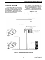
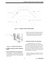
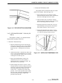
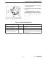
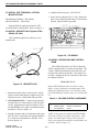
7. Place the PC UPS (TDV-OP400/XX) onto the
swivel mount so that the feet engage the holes.
Refer to Figure 4-1.
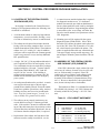
5.1 INTRODUCTION
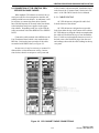
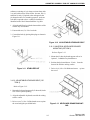
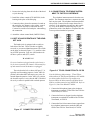
5.3 CONNECT THE PC CPU AND PC UPS POWER CORDS
If you have ordered a CRT-Based console system
installed in E.F. JOHNSON cabinetry, most of the
assembly will already have been done at the factory.
This section, CRT-Based Electronics Assembly - Part
II , details the additional assembly required for either
a complete E.F. Johnson CRT-Based system or an
Electronics Only CRT- Based system.
Part Numbers:
PC UPS - TDV-OP400/xx
PC CPU - 200TC4862501
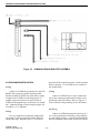
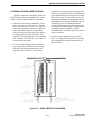
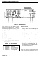
Refer to Figure 5-1.
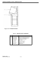
1. Connect one end of the supplied power cord to the
PC CPU. Plug the other end into the top left receptacle at the rear of the PC UPS. (Coil up the excess
cable and secure).
5.2 INSTALL THE PC AND UPS
2. Connect one end of the other supplied power cord to
the PC UPS. Plug the other end into the customerfurnished receptacle box feeding the console.
(Leave enough slack on the power cord so that it
will not unplug when the tray is fully extended).
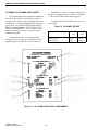
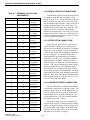
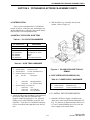
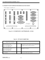
Table 5-1 PC UPS OPTIONS
PC CPU Part No.
200TC4862501
Possible option numbers for the PC UPS
Part Number
Country
North America
TDV-OP400/A
Great Britain, S. Africa
TDV-OP400/GB
Europe
TDV-OP400/E
India
TDV-OP400/I
New Zealand/Australia
TDV-OP400/NZ
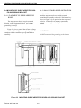
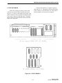
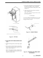
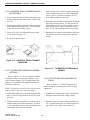
5. Remove the two bottom screws of the PC CPU
(holding the PC cover together) and completely
slide the PC CPU into the PC tray bracket.
6. Replace the two screws that were removed with two
(2) 6-32x1/2 pan head Phillips screws (furnished).
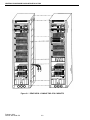
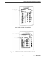
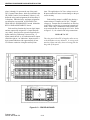
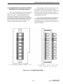
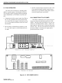
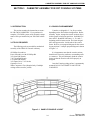
Figure 5-1 CPU AND UPS POWER CONNECTIONS
5-1
February 1996
Part No. 004-3039-274