1
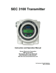
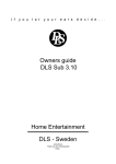
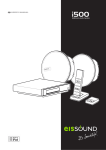
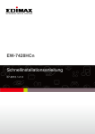
SEC Millenium Carbon Dioxide Gas Detector Instruction and Operation Manual Part Number 71-5000 Version 100201 (SEC) designs and manufactures innovative fixed system gas detection equipment, for combustible gases, oxygen, carbon dioxide and toxic gases. Commitment Our quality and service are uncompromising. We back each of our products with a two-year warranty on all materials and workmanship. We offer technical support, user training and on-site service and maintenance of equipment to meet the needs of our customers. Gas Detection Service Individually designed maintenance packages are available for specific customer needs. Service begins with verification of the system installation that includes an initial system check and calibration. We then offer customer training programs (on-site and at factory) to insure that technical personnel fully understand operation and maintenance procedures. When on-the-spot assistance is required, service representatives are available to handle any questions or problems immediately. Warranty (SEC) warrants products manufactured by SEC to be free from defects in workmanship and materials for a period of two (2) years from date of shipment from the factory. Any parts returned freight pre-paid to the factory and found defective within the warranty would be repaired or replaced, at SEC's option. SEC will return repaired or replaced equipment pre-paid lowest cost freight. This warranty does not apply to items, which by their nature are subject to deterioration or consumption in normal service. Such items may include: Fuses and Batteries. Warranty is voided by abuse including rough handling, mechanical damage, alteration or repair. This warranty covers the full extent of SEC liability and SEC is not responsible for removal, replacement costs, local repair costs, transportation costs or contingent expenses incurred without prior written approval. Sensor Electronics Corporation's obligation under this warranty shall be limited to repair or replacement of any product that has been returned to Sensor Electronics Corporation for warranty consideration. This warranty is expressly in lieu of any and all other warranties expressed or implied, and all other obligations or liabilities on the part of Sensor Electronics Corporation including but not limited to, the fitness for a particular purpose. In no event shall Sensor Electronics Corporation be liable for direct, incidental, or consequential loss or damage of any kind connected with the use of it's products or failure to function or operate properly. Year 2000 Compliance All products have been tested and are certified to accurately process date/time and date/time related data from, into and between the 20th and 21st centuries. Electronic products neither contain nor create any logical or mathematical inconsistency, will not malfunction, and will not cease to function when processing date/time data. Table of Contents I. SPECIFICATIONS II. GENERAL DESCRIPTION III. OPERATION Installation and Startup IV. CALIBRATION V. MAINTENANCE VI. PARTS LIST VII. DRAWING SECTION I. SPECIFICATIONS Model: SEC MILLENIUM Infrared Carbon Dioxide (CO2) Gas Detector Part Number: 142-0617 Specify range when ordering Detection Method: Diffusion Optional sample draw (requires a minimum of 1 liter per minute flow rate) Available Ranges: 0-1% Volume 0-2% Volume 0-5% Volume (1 % volume = 10,000 PPM) High level CO2 (and hydrocarbon gases) monitors available in SEC Signature product line Output (analog): 4-20 mA (Source type), max. 1000 Ohm load at 24 VDC supply voltage Response Time: T50 < 5 seconds T90 < 10 seconds Construction: Sensor housing is nickel-plated aluminum and stainless steel. Optional stainless steel model available. Class 1, Division 1, Groups B, C and D Ingress rating: IP54 Accuracy: +/- 5% measured value or +/- 3% full scale (whichever greater) Operating Temperature Rating: -40° to +70°C at 0 to 99% RH (non-condensing) Operating Voltage: 24 VDC Operating range: 18 to 32 VDC measured at the detector head Power Consumption: 5 Watts Max. Current Draw: (at 24 VDC) Average: 250 mA Peak: 400 mA Approvals: CSA and FM, For -40C to +50C operation Installation Category: Cat. I, Pollution Degree 2 3 II GENERAL DESCRIPTION CONVENTIONS The following conventions are used in this manual. ! Warning Statement VDC (DC Voltage) SEC MILLENIUM The SEC MILLENIUM Infrared gas detector is a microprocessor based intelligent gas detector that continuously monitors carbon dioxide gases and vapors within the specified range. The SEC MILLENIUM is ideally suited for use in harsh environments. The SEC MILLENIUM Infrared gas detector will perform reliably in the presence of poisoning agents and can also operate in oxygen free environments or where high background gas levels are present. There are no known poisons that affect this technology. The SEC MILLENIUM is a stand-alone device providing a continuos 4 to 20 mA output. Features • • • • • • • • • Requires no routine calibration to ensure proper operation. Continuous self-test automatically indicates a fault, with fail to safe operation. A multi-layered filtering system protects optics from dirt and water ingress. Straight optical path eliminates the need for mirrors or reflective surfaces or beam splitters. Performs well in the presence of high concentrations or constant background levels of carbon dioxide and in oxygen depleted atmospheres. Highly resistant to poisoning and etching. Standard 4 to 20 mA output (current source) Explosion proof housing designed for harsh environments. Smart Calibration AutoAC circuit. Infrared Detection Technology The SEC MILLENIUM Infrared gas detector uses infrared absorption technology for detecting carbon dioxide gas (CO2). CO2 absorbs infrared light only at certain wavelengths. The concentration of a gas can be measured by the difference of two channels (wavelengths), a reference and a measurement channel. The SEC MILLENIUM uses a collimated infrared light source that passes through a waveguide, at the end of the waveguide is a dual channel receiver. The dual channel receiver measures the intensity of two specific wavelengths, one at an absorption wavelength and another outside of the absorption wavelength. The gas concentration is determined by a comparison of these two values. 4 Infrared Absorption Spectrum for Carbon Dioxide Transmittance 100% 0% Reference Band Absorption Band Wavelength The dual channel receiver is a single wafer, double filtered, dual receiver with an internal optical barrier. The elements are perfectly matched resulting in overall stability and superior performance throughout the entire temperature range. Dual Channel Receiver Waveguide Infrared Light Source Wiring Connections Window Window Waveguide Collar Hydrophobic Filter Using a dual channel receiver there is no need to use any special lenses or beam splitters to achieve the different measurement bands. The SEC MILLENIUM utilizes a unique patent pending feature, the AutoAC circuit. The AutoAC circuit is an automatic analog control circuit, which allows the SEC MILLENIUM to be calibrated for CO2, provided that a calibration quality level of the gas is available. The optics can be easily disassembled for cleaning. This does not require powering the unit down and does not compromise the units’ explosion proof rating. The device will self compensate for dirty optics until a point in which the optical surfaces are completely obscured. There are no consumable components contained in this product. 5 III. OPERATION Installation and Startup ! Warning: The user shall be made aware that if the equipment is used in a manner not specified by the manufacturer, the protection provided by the equipment may be impaired. The first step in the installation process is to establish a mounting location for the SEC MILLENIUM. Select a location that is typical of the atmosphere to be monitored or close to the anticipated source of a dangerous gas. It is very important that the SEC MILLENIUM be properly located to enable it to provide maximum protection. The most effective number and placement of sensors vary depending on the conditions of the application. When determining where to locate sensors the following factors should be considered. • How rapidly will the gas diffuse into the ambient air? Select a location for the sensor that is close to the anticipated source of a gas leak. • Wind or ventilation characteristics of the immediate area must also be considered. Movement of air may cause gas to accumulate more heavily in one area than in another. The detector should be placed in the areas where the most concentrated accumulation of gas is anticipated. For outdoor applications with strong wind conditions, it may require the sensors to be mounted closer together and on the down wind side, to the anticipated area of a gas leak. Also take into consideration for indoor applications, the fact that many ventilation systems do not operate continuously. • The sensor should be accessible for maintenance. • Excessive heat or vibration can cause premature failure of any electronic device and should be avoided if possible. • Follow all national and local installation codes and practices. • RgasD = 1.53 (Relative density of gas (CO2) referenced to air =1. Indicates how many times a gas is heavier than air at the same temperature). • Normal constitute of air is about 300 PPM of CO2. The SEC MILLENIUM has a ¾ ” NPT threaded connector for mounting the detector to a junction box. SEC can provide a junction box with terminals for this purpose. A user-supplied junction box can be used providing it has the appropriate sized NPT conduit entries. The junction box must be suitable for use in the application and location in which it is being installed. After the device has been installed, a calibration is required. Refer to the Calibration section of this manual. Wiring connections Red wire: 18 to 32 VDC Black wire: DC Common Blue wire: 4 to 20 mA output White wire: Smart Calibration Wire (data wire) Earth Ground: Male 10-32 Stud on SEC Millenium cap, see figure 1. Wire sizing: 0 to 500 feet, recommended wire gauge size 16 AWG 501 to 1000 feet, recommended wire gauge size 14 AWG Shielded cable is recommended. Wiring should be installed in medal conduit with no other cabling in the same conduit. 6 Warm-up When power is applied to the detector, it enters a one (1) minute warm-up mode. The output current will be 0.8 mA during the warm up time period. At the end of the warm-up period with no faults present, the detector automatically enters the normal operating mode (4 mA). If a fault is present after warm-up, the detector current output will indicate a fault. See the following chart for fault code status. Normal In the normal operating mode, the 4 to 20 mA signal levels correspond to the detected gas concentration. The detector continuously checks for system faults or initiation of calibration and automatically changes to the appropriate mode. The 4 to 20 mA output of the SEC MILLENIUM is a non-isolated current source. Current Output and Corresponding Status Current Output 0-20 mA 0.0 mA 0.2 mA 0.4 mA 0.8 mA 1.0 mA 1.2 mA 1.6 mA 2.0 mA 2.2 mA 4.0 mA 20.0 mA 20.1- 23 mA Status. Normal measuring mode Unit Fault Reference channel fault Analytical channel fault Unit warm up Optics fault Zero drift fault Calibration fault Unit spanning Unit zeroing Zero gas level Full scale Over-range (> 100% full scale) Once the fault is cleared the SEC MILLENIUM will atomatically resume normal operation. 7 IV. CALIBRATION SEC MILLENIUM The SEC MILLENIUM is factory calibrated zeroed and spanned. Unlike other types of sensors it does not require routine span gas calibration to ensure proper operation. The SEC MILLENIUM is required to be spanned with gas only one time with CO2. Typically this is done at the factory, but it is possible to field span the device by connecting the SEC MILLENIUM to a computer and using a software package provided by SEC. Please contact the factory for further details. A typical field calibration only requires the use of 99.99% nitrogen. There is a fitting on the bottom of the sensor for a 1/8” ID tubing connection. Before beginning calibration use the SEC MILLENIUM Insulation Tube to cover outer cylinder holes and connect a 99.99% nitrogen source to the sensor’s calibration port for a minimum of 3 minutes. To enter into the calibration mode the calibration wire must be connected to negative (common of the power supply) for ten (10) seconds, upon release the sensor will automatically enter the zero calibration routine. The electronics will automatically adjust the sensor’s signal to the new zero reference level. (Applying span gas is not necessary because of the SEC MILLENIUM’s unique software algorithms). During the zero calibration routine, the current output of the SEC MILLENIUM will go to 2.2 mA. Although this can be accomplished manually, installation of a switch (contact closure) can accomplish the zeroing procedure. It is recommended that this switch be a momentary type switch to prevent it from inadvertently being left in the calibrate position. If after 20 seconds the calibration lead has not been removed from common, the SEC MILLENIUM will ignore the signal and continue operation as normal. V. MAINTENANCE The SEC MILLENIUM does not normally require cleaning of the optics. However if the unit is operating in a very dirty or dusty environment the optical path might become obscured. If the obscuration is severe enough to affect the unit’s accuracy, the unit will activate an “Optics Fault” will. To clear an Optics Fault, first try a calibration. If the calibration does not correct the fault condition, try to clean the optics. The outer barrel (tube with two sets of holes) can be removed (unscrewed) to inspect the cleanliness of the hydrophobic filter. The hydrophobic filter is a Teflon coated stainless steel mesh that keeps moisture and particulates out of the optical path. A setscrew holds the filter to the MILLENIUM’s housing. Once the hydrophobic filter is removed, the internal waveguide tube should be inspected for cleanliness. The waveguide and waveguide collar can be removed by inserting rigid instruments such as Allen wrenches into one hole of the waveguide and one hole of the collar. Turning the two instruments in opposite directions will loosen the waveguide allowing the collar to be screwed down on to the waveguide until it can be removed from the SEC MILLENIUM housing. This will allow the windows of the SEC MILLENIUM to be cleaned. Dust can be removed using compressed air. Hard or oily deposits can be removed using Isopropyl alcohol and cotton tipped swabs. Wipe any film or residue or film left by the alcohol on the windows with a clean dry cotton swab. The internal electro polished wave-guide tube can be cleaned the same way. Be careful not to leave any particles of the cleaning swab in the waveguide. The waveguide holes can collect pieces of the cleaning swab. After reassembling the unit (the waveguide and collar should be very tight to both ends of the SEC MILLLENIUM housing after installation. Once the unit is completely reassembled and power is reapplied, the SEC MILLENIUM must be calibrated. Refer to the calibration section of this manual. 8 VI. Parts List Part Number 142-0617 190-1001 142-0877 142-0497 142-0297 142-0570 142-0636 142-0962 Description Replacement Sensor SEC MILLENIUM (Specify range when ordering) SEC 2001 Sensor Separation Kit SEC Insulation Tube SEC MILLENIUM Replacement Hydrophobic Filter SEC MILLENIUM Wave Guide Tube SEC MILLENIUM Wave Guide Tube Collar SEC IR PC Link Kit SEC MILLENIUM Sample Draw Adaptor 9 VII. Drawing Section Figure # Title Figure 1 Figure 2 Wiring Diagram, SEC MILLENIUM SEC Sensor Separation Kit 10 WHITE: Calibration/Data RED: +24 VDC 3/4“ NPT THREAD BLACK: -24VDC (DC Common) BLUE: 4 TO 20 mA Out OutOUTPUT Earth Ground Stud 10-32 6.5 inches 165mm 2.6 inches 66mm WIRING DIAGRAM MILLENIUM SENSOR FIGURE 1 11 WIRE ENTRY FOR RETURN TO SEC 3100 3/4 NPT WIRE ENTRY FOR SENSOR 3/4 NPT NOTE: HOUSING RATED FOR CLASS 1, DIV 1, GROUPS B, C AND D SEC SENSOR SEPARATION KIT FIGURE 2 12