1
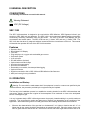
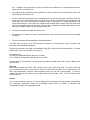
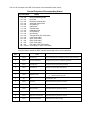
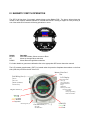
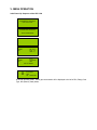
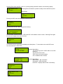
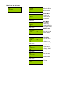
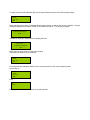
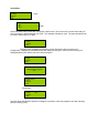
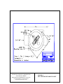
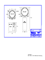
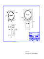
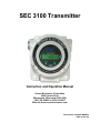
SEC 3100 Transmitter
Instruction and Operation Manual
Sensor Electronics Corporation
5500 Lincoln Drive
Minneapolis, Minnesota 55436 USA
(952) 938-9486 Fax (952) 938-9617
Web site www.sensorelectronics.com
Part Number 3100-EXP-MANUAL
REV 121107-001
Sensor Electronics Corporation
Sensor Electronics Corporation (SEC) designs and manufactures innovative fixed system gas detection
equipment, for combustible gases, oxygen, carbon dioxide and toxic gases.
Commitment
Our quality and service are uncompromising. We back each of our products with a two-year warranty on all
materials and workmanship. We offer technical support, user training and on-site service and maintenance
of equipment to meet the needs of our customers.
Gas Detection Service
Individually designed maintenance packages are available for specific customer needs. Service begins with
verification of the system installation that includes an initial system check and calibration. We then offer
customer training programs (on-site and at factory) to insure that technical personnel fully understand
operation and maintenance procedures. When on-the-spot assistance is required, service representatives
are available to handle any questions or problems immediately.
Warranty
Sensor Electronics Corporation (SEC) warrants products manufactured by SEC to be free from defects in
workmanship and materials for a period of two (2) years from date of shipment from the factory. Any parts
returned freight pre-paid to the factory and found defective within the warranty would be repaired or
replaced, at SEC's option. SEC will return repaired or replaced equipment pre-paid lowest cost freight. This
warranty does not apply to items, which by their nature are subject to deterioration or consumption in normal
service. Such items may include:
Fuses and Batteries.
Warranty is voided by abuse including rough handling, mechanical damage, alteration or repair. This
warranty covers the full extent of SEC liability and SEC is not responsible for removal, replacement costs,
local repair costs, transportation costs or contingent expenses incurred without prior written approval.
Sensor Electronics Corporation's obligation under this warranty shall be limited to repair or replacement of
any product that has been returned to Sensor Electronics Corporation for warranty consideration. This
warranty is expressly in lieu of any and all other warranties expressed or implied, and all other obligations or
liabilities on the part of Sensor Electronics Corporation including but not limited to, the fitness for a particular
purpose. In no event shall Sensor Electronics Corporation be liable for direct, incidental, or consequential
loss or damage of any kind connected with the use of it's products or failure to function or operate properly.
Year 2000 Compliance
All Sensor Electronics products have been tested and are certified by Sensor Electronics to accurately
process date/time and date/time related data from, into and between the 20th and 21st centuries. Sensor
Electronics products neither contain nor create any logical or mathematical inconsistency, will not
malfunction, and will not cease to function when processing date/time data.
Please contact Sensor Electronics for further information.
Table of Contents
I.
SPECIFICATIONS
II.
GENERAL DESCRIPTION
III.
OPERATION
Installation and Startup
Fault Codes
IV.
MAGNETIC SWITCH OPERATION
V.
FIGURES
Figure 1 – Overall Layout
Figure 2 – SEC 3100 Wiring
Figure 3 – SEC Sensor Separation Kit
I. SPECIFICATIONS
Model:
SEC 3100 Transmitter
For use with:
SEC Millenium and SEC Signature series infrared sensors and SEC 3000 Toxic and Oxygen gas sensors.
Part Number: SEC 3100100
Output (analog):
4-20 mA (Source type), max. 1000 Ohm load at 24 VDC supply voltage
Output (digital):
RS485 LAN (isolated)
Output (relays):
Three (3) Alarm, Low, Mid High. One (1) Fault
Rated for 8 Amps 30 VDC or 220VAC
Display:
LCD (backlit)
Construction:
Epoxy coated aluminum
Class 1, Division 1, Groups B, C and D
Operating Temperature Rating:
-40° to +158° F at 0 to 99% RH (non-condensing)
(-20° to +70°C)
Operating Voltage:
24 VDC
Operating range: 18 to 30 VDC measured at the detector head
Max. Current Draw: (at 24 VDC with sensor)
Average: 250 mA
Peak: 500 mA
Installation Category: Cat. I, Pollution Degree 2
II GENERAL DESCRIPTION
CONVENTIONS
The following conventions are used in this manual.
!
Warning Statement
VDC (DC Voltage)
SEC 3100
The SEC 3100 transmitter is designed to be used with the SEC Millenium, SEC Signature infrared gas
sensors or SEC 3000 toxic gas detectors. The SEC 3100 is a microprocessor based intelligent transmitter
continuously monitoring information from the gas sensor. The LCD of the SEC 3100 displays the gas
concentration and sensor status. The SEC 3100 has one (1) “Alarm” LED and one (1) “Status” LED. The
SEC 3100 also has three (3) magnetic switches located around the circumference of the unit. This manual
will describe the operation and use of the SEC 3100 transmitter.
Features
•
•
•
•
•
•
•
•
•
•
•
•
•
•
Explosion Proof
Back lighted LCD Display
Low Cost
Plug and play toxic, oxygen and combustible gas sensors
Self-check system
4-20 mA ouput
RS-485 Interface (Isolated)
Optional alarm and fault relays
Non-intrusive programming
Non-intrusive calibration
Removable, non-volatile, time stamped data logging
Optional IS barrier
Digital communication link to SEC 3000 and SEC Millenium Gas Detectors
Multi port housing for easy installation
III. OPERATION
Installation and Startup
!
Warning: The user shall be made aware that if the equipment is used in a manner not specified by the
manufacturer, the protection provided by the equipment may be impaired.
The first step in the installation process is to establish a mounting location for the SEC 3100 transmitter and
gas sensor. Select a location that is typical of the atmosphere to be monitored or close to the anticipated
source of a dangerous gas.
It is very important that the SEC 3100 and gas sensor be properly located enabling it to provide maximum
protection. The most effective number and placement of sensors vary depending on the conditions of the
application. When determining where to locate gas sensors the following factors should be considered.
•
What are the characteristics of the gas that is to be detected? Is it lighter or heavier than air? If it is
lighter than air the sensor should be placed above the potential gas leak. Place the sensor close to the
floor for gases that are heavier than air. Note that air currents can cause a gas that is heavier than air to
rise. In addition, if the temperature of the gas is hotter than ambient air or mixed with gases that are
lighter than air, it could also rise.
•
How rapidly will the gas diffuse into the ambient air? Select a location for the sensor that is close to the
anticipated source of a gas leak.
•
Wind or ventilation characteristics of the immediate area must also be considered. Movement of air may
cause gas to accumulate more heavily in one area than in another. The detector should be placed in the
areas where the most concentrated accumulation of gas is anticipated. For outdoor applications with
strong wind conditions, it may require the sensors to be mounted closer together and on the down wind
side, to the anticipated area of a gas leak. Also take into consideration for indoor applications, the fact
that many ventilation systems do not operate continuously.
•
The sensor should be accessible for maintenance.
•
Excessive heat or vibration can cause premature failure of any electronic device and should be avoided
if possible.
•
Follow all national and local installation codes and practices.
The SEC 3100 has three (3) ¾” NPT threaded connectors for mounting and wiring the sensor and
transmitter into a permanent installation.
Field wiring connections are made on the backside of the SEC 3100 printed circuit board (PCB). For wiring
details refer to Figure 2 in the back of the manual.
Power wire sizing:
0 to 500 feet, recommended wire gauge size 16 AWG
501 to 1000 feet, recommended wire gauge size 14 AWG
Shielded cable is recommended. Wiring should be installed in medal conduit with no other cabling in the
same conduit.
Warm-up
When power is applied to the SEC 3100, it enters a one (1) minute warm-up mode. The output current will
be 0.8 mA during the warm up time period. At the end of the warm-up period with no faults present, the
SEC 3100 automatically enters the normal operating mode (4.0 mA with no gas present). If a fault is
present after warm-up, the detector current output and LCD will indicate a fault. The Fault LED will also
indicate the fault.
Normal
In the normal operating mode, the 4 to 20 mA signal levels correspond to the detected gas concentration.
The transmitter continuously checks for and displays system faults or initiation of calibration and
automatically changes to the appropriate mode.
The 4 to 20 mA output of the SEC 3100 sensor is a non-isolated current source.
Current Output and Corresponding Status
Current Output
0-20 mA
0.0 mA
0.2 mA
0.4 mA
0.8 mA
1.0 mA
1.2 mA
1.6 mA
2.0 mA
2.2 mA
4.0 mA
5.6 mA
8.0 mA
12 mA
16 mA
20 mA
20.1- 23 mA
Status
Normal measuring mode
Unit Fault
Reference channel fault
Analytical channel fault
Unit warm up
Optics fault
Zero drift fault
Calibration fault
Unit spanning
Unit zeroing
Zero gas level (0% of full scale)
(10% of full scale)
(25% of full scale)
(50% of full scale)
(75% of full scale)
Full scale (100% of full scale)
Over-range (> 100% of full scale)
Once the fault is cleared the SEC 3100 will atomatically resume normal operation.
Flash
Rate
Output Current
1
4-20ma
2
Unit Status
Label
Possible Problem
Unit Running
Unit is measuring gas and adjusting 4-20ma output accordingly.
2.2ma
Unit Zero Calibrating
Unit going through its zero calibration procedure.
3
2.0ma
Unit Spanning
Unit going through its spanning procedure.
5
0.8ma
Unit Warm-up
Only for one minute after unit power-up
6
0.0ma
Power-up Fault
Hard Fault (refer to gas sensor manual)
7
1.6ma
Calibration Fault
8
NA
9
1.
2.
Attempt Unit Span with no gas
Attempt Unit Zero with gas
NA
Currently Not Used
0.0ma
Unit Fault
Hard Fault (refer to gas sensor manual)
10
1.0ma
Optics Fault
Clean sensor’s windows
11
1.2ma
Zero Drift Fault
Hard Fault (refer to gas sensor manual)
12
0.0ma
Configuration Fault
Hard Fault (refer to gas sensor manual)
16
0.2ma
Reference Channel Fault
Hard Fault (refer to gas sensor manual)
17
0.4ma
Active Channel Fault
Hard Fault or Unit Zero with gas
IV. MAGNETIC SWITCH OPERATION
The SEC 3100 has three (3) magnetic switch pickups on the Display PCB. The picture below shows the
location of the magnetic switches labeled UP, DOWN and ENTER. Placing a magnet in close proximity to
one of the switches will cause the following operations to occur.
Switch
ENTER
UP
DOWN
Operation
Enter Menu Mode, Selects a menu to Enter
Moves up through Menu selections
Moves down through Menu selections
For further details on gas sensor calibration refer to the appropriate SEC sensor instruction manual.
The LCD contrast potentiometer, (POT1) is located under the protective faceplate shown above on the front
side (LCD side) of PCB to the left of the LCD.
Memory Data Card
Slot
Field Wiring Port (2 x ¾ h)
LCD Display:
¾Power
¾4-20 mA
¾RS485 (MODBUS)
¾Alarm Relays
Real Time Status
Gas Type
Gas Concentration
Fault Identification
Range
ID Number
Memory Card Status
Interactive Menus
Calibration
Relay Programming
ID & Zone Number
Magnetic Switch (3)
Alarm LED
Green OK
Yellow Low Alarm
Orange Mid Alarm
Red High Alarm
Mounting holes (2)
Gas Sensor Port (1 x
SEC 3000
SEC Millenium
¾ h
)
Fault LED
Green OK
Red Fault
V. MENU OPERATION
Inital Power Up Sequence of the SEC 3100
SYSTEM BOOT PROCESS
--- WAIT FOR SYNC –-
SYSTEM BOOT PROCESS
-WAIT FOR SENSOR -
INITIALIZING
WARM
UP
WARM
UP
0
ID: xx
SN: xxxxx
TYP: x.x
VER: x.x
ID: xx
0-20.0PPM
WF6
ENT TO ABORT
ID: 1
0-20.0 PPM
WF6
MC - REMOVED
In normal operating mode. Actual gas concentration will be displayed to the left of ID #, Range, Gas
Type, MC (Memory Card) status.
Selecting Enter when the SEC 3100 in in normal operating mode will advance to the following display:
* EJECT MEMORY CARD
INFO
MAIN MENU
Down Arrow
Selecting Enter will allow the operator to safely remove the Memory Card.
Arrow Down
EJECT MEMORY CARD
* INFO
MAIN MENU
Entering the INFO menu will display the following screen
* UNIT INFO
SENSOR INFO
STATS
EXIT
Selecting Enter at UNIT INFO displays the following:
3100 UNIT INFO:
SN- XXXXXXXXXXXXXXX
VER- X
X.XXX.XXX
SN is the SEC 3100 serial number. VER is the SEC 3100 software version number. Selecting Enter again
will return the display to the main info menu.
* UNIT INFO
SENSOR INFO
STATS
EXIT
The following are the other INFO sub displays and descriptions. To return back to the main INFO menu
from the sub menus, select Enter.
SENSOR INFO:
TYP: XXX
SN: XXXXX VER: XX.X
CAL: XX – XX - XXXX
SYSTEM STATS:
RBR COUNT : XXX
ICE COUNT : XXX
BATTERY
: XXX
.
UNIT INFO
SENSOR INFO
STATS
* EXIT
Select Exit to go back to
EJECT MEMORY CARD
* INFO
MAIN MENU
Sensor Status Menu
TYP: Sensor type (0.0 is a SEC 3000, 32.0 is SEC
Millenium)
SN: Sensor serial number.
VER: Version of sensor software.
CAL: Calibration date of sensor.
Sensor Status Menu
RBR COUNT : SEC information
ICE COUNT : SEC information
BATTERY : Displays status of SEC 3100 battery
Main Menu and Sub Menus
EJECT MEMORY CARD
INFO
* MAIN MENU
Enter
Calibration Menu
Used to calibrate
the gas sensor.
* CALIBRATION
ALARM
RELAY
Down Arrow
Alarm Menu
Used to set
alarm level set
points and
parameters.
CALIBRATION
* ALARM
RELAY
Down Arrow
Relay Menu
For setting
alarm relay
On & Off delay &
Energized states.
CALIBRATION
ALARM
* RELAY
Down Arrow
* NETWORK
HIDE
NO
Network Menu
Used to set
Zone #, ID # and
Select Online
Down Arrow
NETWORK
* HIDE
NO
Hide Menu
Hide is used to
blank the
display up to
low alarm setting
Down Arrow
* SELF TEST
DATE TIME
Self Test Menu
Generates a
signal on the
display, RS485
& 4-20 mA
Down Menu
SELF TEST
* DATE TIME
Date Time Menu
Sets the date
and time in the
real time clock.
Down Arrow
* EXIT
Exit back to
normal
operation.
Calibration Menu
* CALIBRATION
ALARM
RELAY
Enter
Using the Up and Down arrows allows the operator to move the cursor (*) to select a function.
* ZERO
SPAN
CAL. VAL
EXIT
0
To Zero the sensor apply clean air (N2 for an oxygen sensor) and select enter. The following will be
displayed.
CALIBRATION PROCESS
------- WAIT ----------
Then the following will be displayed.
CALIBRATION PROCESS
------- DONE ----------
Once complete the following will be displayed. The sensor has been successfully zeroed.
* ZERO
SPAN
CAL. VAL
EXIT
0
Arrow down to CAL. VAL to verify the span gas calibration value matches the value of the span gas
calibration on hand. If not, select Enter and the following screen will appear.
ZERO
SPAN
* CAL. VAL
EXIT
5
*
Using the Up and Down arrows will allow the operator to change the calibration gas value of the sensor to
match the calibration gas used to span the sensor. Once the correct value is displayed select Enter and the
sensor will be uploaded with the new calibration gas value.
To Span the sensor with calibration gas use the Up and Down arrows to select the following display.
ZERO
* SPAN
CAL. VAL
EXIT
3
Apply span gas to the sensor for the appropriate amount of time in order for the sensor to stabilize. The gas
reading is displayed to the right of ZERO. Once stable select Enter. This will go the display:
CALIBRATION PROCESS
------- DONE ----------
If calibration span gas is still present the display will read:
GAS LEVEL : 5
CALIB. GAS PRESENT
---WAIT ----
Apply clean air to the sensor to reduce this reading.
The display will advance to the following:
* ZERO
SPAN
CAL. VAL
EXIT
0
This completes the calibration and the device can be put back into the normal operating mode.
Arrow Down to
ZERO
SPAN
CAL. VAL
* EXIT
Enter
* EXIT
Enter again and the SEC 3100 returns to normal operation.
Alarm Menu
CALIBRATION
* ALARM
RELAY
Enter
* LOW
MID
HI
EXIT
Enter
Select the Alarm Relay (LOW, MID, HI) using the down arrow. Once the cursor is on the alarm relay you
wish to configure, hold the magnet over Enter. The example LOW will be used. The same operations can
be used to set the MID or HI relays.
* ALARM LOW 4
LATCH
ACTIVE
EXIT
Selecting Enter will display the following screen allowing the alarm set point to be
programmed. Using the Up and Down arrows will change the set point. Once the correct set point is
displayed select Enter and the new value will be accepted.
* ALARM LOW 2
LATCH
ACTIVE
EXIT
*
CONFIGURING PROCESS
------ WAIT -------
* ALARM LOW 2
LATCH
ACTIVE
EXIT
Arrow Down
ALARM LOW
* LATCH
ACTIVE
EXIT
NO
Selecting Enter will allow the operator to change the operation of the relay operation from Non-Latching
(NO) to Latching (YES).
Arrow Down
ALARM LOW
LATCH
* ACTIVE
EXIT
HI
Selecting Enter will allow the operator to change the operation of the relay operation from Active HI to Active
LOW. HI activates the relay on a rising alarm level. LOW actives the relay when the alarm threshold falls
below the alarm set point. Once the correct operation is selected, use the Down arrow to advance to the
next menu item.
Arrow Down
ALARM LOW
LATCH
ACTIVE
* EXIT
Selecting Exit will advance to the next menu.
* LOW
MID
HI
EXIT
This menu will allow the operator to select another relay to program. Or select Exit and the next display will
be:
* EXIT
Selecting Enter on this display will put the SEC 3100 back into normal operation.
Relay Menu
CALIBRATION
ALARM
* RELAY
Selecting Enter will advance to the following menu.
* LOW
MID
HI
Arrow down to the next screen will be
* FAULT
EXIT
Select the Alarm Relay (LOW, MID, HI, FAULT) that is to be configured using the down arrow. Once the
cursor is on the correct alarm relay, hold the magnet over Enter. The example LOW will be used. The
same operations can be used to set the MID, HI, or FAULT relays.
* LOW
MID
HI
Select Enter
* ON DLY LOW
OFF DLY
ENERGIZED
EXIT
0
* ON DLY LOW
OFF DLY
ENERGIZED
EXIT
0
Select Enter
*
Using the Up and Down arrows the operator can change the ON delay time for the relay to actuate after the
alarm threshold has been exceeded. The time is measured in seconds (0-255). Once the correct time is
displayed select Enter to accept the new value. Then Exit the menu and proceed on to the next selection.
In this example the Low alarm relay will actuate 30 seconds after the Low set point is exceeded.
* ON DLY LOW
OFF DLY
ENERGIZED
EXIT
30
Select Enter
ON DLY LOW
* OFF DLY
ENERGIZED
EXIT
0
Select Enter
ON DLY LOW
* OFF DLY
EXIT
0
*
Using the Up and Down arrows the operator can change the OFF delay time for the relay to turn OFF after
the reading has decreased below the alarm point threshold. The time is measured in seconds (0-255).
Once the correct time is displayed select Enter to accept the new value. Then Exit the menu and proceed
on to the next selection.
In this example the Low alarm relay will stay energized for 60 seconds after the alarm has cleared.
ON DLY LOW
* OFF DLY
ENERGIZED
EXIT
60
Arrow Down
ON DLY LOW
OFF DLY
* ENERGIZED NO
EXIT
Selecting Enter will allow the operator to change the operation of the relay coil from normally de-energized
(ENERGIZED NO) to normally energized (ENERGIZED YES). Once the correct operation is selected, use
the Down arrow to advance to the EXIT menu. Select Enter to go back to the Relay Menu
* LOW
MID
HI
This menu will allow the operator to select another relay to program. Or select Exit and the next display will
be:
* FAULT
EXIT
Arrow Down to Exit
FAULT
* EXIT
Enter
* EXIT
Selecting Enter will return the SEC 3100 into normal operation.
Network Menu
* NETWORK
HIDE
Select Enter
* ZONE 0
ID
ONLINE
EXIT
Select Enter to change the Zone number of the SEC 3100.
* ZONE 0
ID
ONLINE
EXIT
*
Use the Up and Down Arrows change the Zone number (0-255). Once the correct Zone number is
displayed select Enter.
Arrow Down to ID. To change the ID number select Enter. Use the Up and Down Arrows to change the ID
number (0-255). Once the correct ID number is displayed select Enter.
ZONE
* ID
1
ONLINE
EXIT
*
Arrow Down to Online.
ZONE
ID
* ONLINE
EXIT
YES
Using Enter the operator can toggle between Online YES and Online NO. Online YES turns on the MODUS
RS485 communication. Online NO turns the MODBUS RS485 communication off.
Arrow Down to Exit
ZONE
ID
ONLINE
* EXIT
Enter
* EXIT
Hide Menu
NETWORK
* HIDE
NO
Using Enter the operator can toggle between Hide YES and Hide NO.
The Hide function allows the operator to not display the gas reading until the Low Alarm threshold is
exceeded. All outputs will function as normal when the Hide mode selected to YES.
Self Test Menu
* SELF TEST
DATE TIME
Selecting Enter for the Self Test will make the sensor generate a 4-20 mA input into the SEC 3100 from 4
mA to 20 mA (0-fullscale). In the self test mode the SEC 3100 outputs are fully functional. The SEC 3100
will display the rising gas level, the 4-20 mA output will increase to 20 mA, the relays will actuate and the
RS485 information will be transmitted to the control system. The following screen will be displayed
10.4
ID: 1
0-20.0 PPM
WF6
SELF TESTD
Once the unit reaches full scale the SEC 3100 automatically returns to normal.
Time Date Menu
SELF TEST
* DATE TIME
Entering this menu will allow the operator to set the time and date of the SEC 3100 real time clock.
* DATE
TIME
EXIT
1
/ 30
/ 2006
Selecting Enter will locate a cursor (*) above the number allowing the operator to use the Up Down arrows
to increase or decrease the numbers. Once the correct number is displayed, select Enter with the magnet
and the cursor will advance to the next number.
Date is MM/DD/YYYY. Time is HH/MM/SS. Below is an example.
Enter from above display.
*
1 / 30
* DATE
TIME
EXIT
/ 2006
Arrow Up one number.
* DATE
TIME
EXIT
*
2 / 30
/ 2006
*
/ 30
/ 2006
Enter
* DATE
TIME
EXIT
2
Continue with the sequence until the correct date appears. Then select Enter and the following will be
displayed.
* DATE
TIME
EXIT
2
/ 15
/ 2006
At this point the operator can advance to setting the correct time using the Down Arrow.
DATE
* TIME
EXIT
14 :
33 :
04
Time numbers are changed using the procedure as the Date numbers. Once the correct Time is
programmed, select Enter and arrow down to Exit.
DATE
TIME
* EXIT
Select Enter
* EXIT
Selecting Enter again will return the SEC 3100 to normal operation.
Diagnostics Menu
* DIAGNOSTICS
REST RELAYS
EXIT
The Diagnostics Menu will allow the operator to enter the Locator Mode and Toggle Relays on and off to
verify operation.
Selecting Enter will display the following:
* LOCATOR OFF
TOGGLE RELAYS
EXIT
The Locator function is normally generated by the SEC 3500 operator interface. It can be used at the SEC
3100 to function as a lamp test. Selecting Enter will turn the Locator on.
* LOCATOR ON
TOGGLE RELAYS
EXIT
The Alarm and Fault LEDs will flash red and green alternately.
Selecting Enter again will turn the Locator function off.
Arrow Down to Toggle Relays (manual relay control)
LOCATOR
* TOGGLE RELAYS
EXIT
Selecting Enter will display the following:
* LOW
MID
HI
* FAULT
EXIT
Select the Alarm Relay (LOW, MID, HI, FAULT) that is to be configured using the down arrow. Once the
cursor is on the correct alarm relay, hold the magnet over Enter. The example LOW will be used. The
same operations can be used to manually control the MID, HI, or FAULT relays.
* LOW
MID
HI
OFF
Selecting Enter will manually turn on the relay, selecting Enter again will turn off the relay.
Reset Relays Menu
DIAGNOSTICS
* RESET RELAYS
EXIT
The Reset Reset relays Menu will allow the operator to reset latched relays.
Latched relays will be indicated by a blue flashing Alarm LED. Select Enter and any latched relays will be
reset.
V. FIGURES
Figure 1 – Overall Layout
Figure 2 – SEC 3100 Wiring
Figure 3 – SEC Sensor Separation Kit
Figure 4 – Mounting SEC 3100 and SEC Millenium
Figure 5 – Mounting SEC 3100 and SEC 3000
LCD Display:
Real Time Status
Gas Type
Gas Concentration
Fault Identification
Range
ID Number
Memory Card Status
Interactive Menus
Calibration
Relay Programming
ID & Zone Number
Memory Data Card
Slot
Field Wiring Port (2 x ¾ h)
¾Power
¾4-20 mA
¾RS485 (MODBUS)
¾Alarm Relays
Mounting holes (2)
Magnetic Switch (3)
Fault LED
Green OK
Red Fault
Alarm LED
Green OK
Yellow Low Alarm
Orange Mid Alarm
Red High Alarm
Gas Sensor Port (1 x
¾ h
)
SEC 3000
SEC Millenium
SENSOR ELECTRONICS CORPORATION
5500 LINCOLN DRIVE
MINNEAPOLIS, MINNESOTA 55436 USA
(T) 952.938.9486 (F) 952.938.9617
[email protected]
FIGURE 1
SEC 3100 OVERVIEW
TB 1
RELAY
WIRING
TB 3
SENSOR
WIRING
TB 2
POWER,
DATA HWY,
ANALOG
OUTPUT
TB 1
(12) LOW ALARM N.C.
(11) LOW ALARM COMMON
(10) LOW ALARM N.O.
(9) MID ALARM N.C.
(8) MID ALARM COMMON
(7) MID ALARM N.O.
(6) HIGH ALARM N.C.
(5) HIGH ALARM COMMON
(4) HIGH ALARM N.O.
(3) FAULT (N.E.) N.C.
(2) FAULT (N.E.) COMMON
(1) FAULT (N.E.) N.O.
TB 2
(1) 4-20 mA ANALOG OUTPUT
(2) DC COMMON
(3) +24 VDC
(4) DATA ISO COMMON
(5) RS485 DATA B
(6) RS485 DATA A
SENSOR ELECTRONICS CORPORATION
5500 LINCOLN DRIVE
MINNEAPOLIS, MINNESOTA 55436 USA
(T) 952.938.9486 (F) 952.938.9617
[email protected]
TB 3
(1) WHITE
(DATA/CAL)
(2) BLUE OR GREEN
(4-20 mA)
(3) RED
(+24 VDC)
(4) BLACK
(DC COMMON)
FIGURE 2
BACK VIEW OF SEC 3100
SEC 3100 WIRING
SENSOR ELECTRONICS CORPORATION
5500 LINCOLN DRIVE
MINNEAPOLIS, MINNESOTA 55436 USA
(T) 952.938.9486 (F) 952.938.9617
[email protected]
FIGURE 3
SEC SENSOR SEPARATION KIT
FIGURE 4
SEC 3100 – SEC Millenium Mounting
FIGURE 5
SEC 3100 – SEC 3000 Mounting