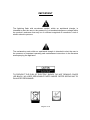
1
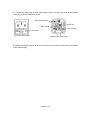
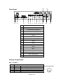
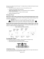
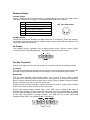
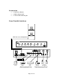
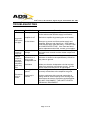
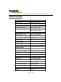
Installation & Operation Guide ADS 3120 Plus 120W ac/dc Mixer Amplifier PLEASE NOTE: THIS MANUAL AND THE NOTES CONTAINED HEREIN ARE COPYRIGHT AND MAY NOT BE REPRODUCED EITHER WHOLLY OR IN PART, IN ANY WAY WHATSOEVER, WITHOUT WRITTEN CONSENT OF ADSworldwide. Audio Design Services Ltd, St David’s House, Adcroft St, Higher Hillgate, Stockport, Cheshire SK1 3HW, UK. TEL: +44 (0)161 666 6363 FAX: +44 (0)161 666 6366. WEB: www.ads-worldwide.net © 2008 Product Compliance to EC directives for Standard Products All standard products conform to the relevant directives, regulations and standards for electronic and associated apparatus. The equipment is CE marked both on the apparatus and the packaging. Our products meet the appropriate British and International standards. A product ‘Declaration of Conformity’ Statement is available for each of the product ranges (available on request). This covers both the EMC and Low Voltage Directives. UNPACKING While all ADSworldwide equipment is carefully packed to prevent damage in transit, we recommend that the equipment is unpacked and inspected immediately on receipt. If damage has occurred please advise your carrier and your supplier who will arrange appropriate action. If it is necessary to re-pack the equipment for onward shipping or returning to ADSworldwide for service PLEASE ENSURE THAT THE ORIGINAL PACKING OR EQUIVALENT IS USED. Page 2 of 16 IMPORTANT The lightning flash with arrowhead symbol, within an equilateral triangle, is intended to alert the user to the presence of un-insulated dangerous voltage within the product's enclosure that may be of sufficient magnitude to constitute a risk of electric shock to persons. The exclamation mark within an equilateral triangle is intended to alert the user to the presence of important operating and maintenance instructions in the literature accompanying the appliance. TO PREVENT THE RISK OF ELECTRIC SHOCK, DO NOT REMOVE COVER (OR BACK). NO USER SERVICABLE PARTS INSIDE. REFER SERVICING TO QUALIFIED PERSONNEL. Page 3 of 16 TABLE OF CONTENTS INTRODUCTION .................................................................................................... 5 Features .............................................................................................................................. 5 Safety Information............................................................................................................... 5 OPERATION ........................................................................................................... 7 General Installation ............................................................................................................. 7 Front Panel ......................................................................................................................... 7 Rear Panel .......................................................................................................................... 8 Priority Connections ........................................................................................................... 8 MIC 1 and MIC 2 .......................................................................................................................... 8 Input Connections ............................................................................................................... 9 MIC 1 and MIC 2 .......................................................................................................................... 9 MIC 3 and AUX 1 ......................................................................................................................... 9 MIC 4, MIC 5, AUX 2 and AUX 3 .................................................................................................9 Phantom Power ................................................................................................................ 10 Loudspeaker Output ......................................................................................................... 10 Loudspeaker Loading ................................................................................................................. 10 Booster Output.................................................................................................................. 11 Variable Output .......................................................................................................................... 11 Fixed Output ............................................................................................................................... 11 dc Power ........................................................................................................................... 11 Facility Terminals .............................................................................................................. 11 dc Output .................................................................................................................................... 11 Restoration ................................................................................................................................. 11 Accessories ...................................................................................................................... 12 Some Possible Interfaces ................................................................................................. 12 TROUBLESHOOTING .......................................................................................... 13 SPECIFICATIONS ................................................................................................ 14 NOTES ................................................................................................................. 15 WARRANTY CONDITIONS .................................................................................. 16 Page 4 of 16 Audio Design Services Ltd., St David’s House, Adcroft Street, Higher Hillgate, STOCKPORT SK1 3HW. INTRODUCTION Features The ADS 3120 Plus is a 120 watt rms, two-zone, mixer amplifier suitable for powering medium to large sound systems where music may be required in one area and quiet in the rest of the building. Messages can be relayed to both areas using the priority switching system. Features include 220-240Vac at 50Hz or 24Vdc power operation two balanced microphone inputs (MIC 1 and MIC 2) with priority paging & chime three more balanced inputs switchable between microphone and line level two outputs - one for speech and music, one for speech only (this facility is only available on MIC 1 and MIC 2) each input has phantom power facility volume controls for all inputs, located on the front panel separate bass, treble and master volume controls, located on the front panel supplied with 19-inch rack mount ears. Additional features on the new version (Plus) of the ADS 3120 include XLR and ¼ inch 3-pole jack combination sockets for MIC 1, MIC 2 and MIC 3 5-pin DIN sockets for MIC 1 and MIC 2 (to accept microphones fitted with a 5-pin DIN plug – e.g. the ADS Signet 1A) volume restoration trim control on MIC 1 and MIC 2. Safety Information WARNING – THIS APPLIANCE MUST BE EARTHED IMPORTANT The wires in the mains lead are coloured in accordance with the following code Green and yellow Earth (E); Blue: Neutral (N); Brown: Live (L). As the colours of the wires in the mains lead of the apparatus may not correspond with the coloured markings identifying the terminals in your plug proceed as follows the wire coloured green and yellow must be connected to the terminal marked by the letter E (or the safety earth symbol), or coloured green and yellow the wire coloured blue must be connected to the terminal marked with the letter N or coloured black the wire coloured brown must be connected to the terminal marked with the letter L or coloured red. Page 5 of 16 If a 13-amp (BS1363) plug or other type of plug is used, a 5-amp fuse must be fitted either in the plug or at the distribution board. Green/Yellow Earth Brown Live Blue Neutral Fuse (max 5A) Fuse Holder IEC Mains Inlet Socket 13A Mains Plug Wiring (UK) For mains connection other than in the UK, refer to your local requirements for connection to the mains supply. Page 6 of 16 Audio Design Services Ltd., St David’s House, Adcroft Street, Higher Hillgate, STOCKPORT SK1 3HW. OPERATION General Installation ALWAYS ensure that the equipment is properly earthed (grounded). Operating without an earth is dangerous and may cause high levels of audible hum from the speaker outputs. NEVER remove the top cover of the amplifier or make an internal adjustment with the ac mains supply connected. All internal servicing should be performed by a competent and qualified engineer. DO NOT expose the unit to rain or moisture. If any fluids or foreign objects should enter the unit, disconnect the power plug immediately. DO NOT site the equipment in locations exposed to direct sunlight, near heaters or other heat sources. Avoid locations with high humidity or dust levels. DO NOT obstruct the ventilation slots in the amplifier case and allow adequate ventilation. (Ensure that a 1U ventilation panel is fitted above the unit if the amplifier is rack-mounted.) DO NOT run microphone cables near mains, data, telephone or 100V lines. AVOID jointing the microphone cables if possible. If this is unavoidable, make sure a good screen connector is used. ALWAYS use a balanced or floating low impedance microphone on long microphone runs, terminating in a balanced input. Front Panel 1 2 3 4 5 6 7 8 9 10 11 1 OVERLOAD LED INDICATOR 7 BASS CONTROL 2 MIC 1 8 TREBLE CONTROL 3 MIC 2 9 MASTER GAIN 4 MIC 3 / AUX 1 10 POWER LED 5 MIC 4 / AUX 2 11 POWER ON/OFF SWITCH 6 MIC 5 / AUX 3 Page 7 of 16 28 Rear Panel 27 26 12 13 14 15 16 17 18 19 20 21 22 12 MAINS SOCKET 13 DC IN TERMINALS 14 LOUDSPEAKER TERMINALS 15 BOOSTER OUT (VARIABLE) 16 BOOSTER OUT (FIXED OR VARIABLE) 17 AUX 3 18 MIC 5 19 AUX 2 20 MIC 4 21 AUX 1 22 MIC 3 23 MIC 2 24 MIC 1 25 MIC 1 Priority Connection 26 MIC 2 Priority Connection 27 MIC 1 Trim Control 28 MIC 2 Trim Control 25 23 24 Priority Connections MIC 1 and MIC 2 Pin 1 2 3 4 5 Signal + Ground Signal Access Access Function Positive signal input from the microphone. Connect to chassis or screen. Negative signal input from the microphone. Close pins 4 and 5. For priority access. Close pins 4 and 5. For priority access. Page 8 of 16 180o 5-pin DIN socket Input Connections MIC 1 and MIC 2 Microphone inputs 1 and 2 use an XLR / ¼” 3-pole jack combination socket and a 180˚ 5-pin DIN socket. Any of these connectors may be used. However if priority is required it may be easier to use the DIN socket and compatible ADS Signet microphone. (See Priority Connections 25 and 26 and wiring table on Page 8 for the DIN socket.) XLR/Jack Combination Socket Balanced XLR Plug Pin Configuration Unbalanced The connections on an XLR plug are numbered 1 to 3 and should be connected as follows Pin 1: Ground (or Screen). Pin 2: Signal+ (or Hot). PIN 3: Signal- (or Cold) If the signal source is not balanced then Pin 1 should be connected to Pin 3 along with the Ground (or Screen). Each of the microphone inputs 1 and 2 is provided with a trim control on the rear panel (see diagram on Page 8). This control adjusts the sensitivity of the input to allow for a wide range of input sources. Adjust this control to reduce noise and provide an acceptable, undistorted output level. MIC 3 and AUX 1 This microphone input uses an XLR / ¼” 3-pole jack combination socket (see above) and is balanced. There are no priority functions available with this input. The input can be reconfigured as an auxiliary input as follows disconnect the power supply then remove the amplifier top cover locate the correct switch on the rear PCB (Three switches are located on the rear PCB. The switch required is the left hand one when viewed from the front of the amplifier) set the switch to the position nearest to the rear panel replace the amplifier top cover. The auxiliary input uses a phono connection (see below). Pin (Signal) Sleeve (Screen) MIC 4, MIC 5, AUX 2 and AUX 3 Each microphone input uses a ¼” 3-pole jack connection (see below). Ring (Signal-) Tip (Signal+) Sleeve (Screen) Each auxiliary input uses a phono connection (see above). Page 9 of 16 All inputs are configured as AUX inputs. To configure them as balanced microphone inputs proceed as follows disconnect the power supply then remove the amplifier top cover locate the correct switch on the rear PCB (MIC 4 is the centre one and MIC 5 the right hand one when viewed from the front of the amplifier) set the switch to the position nearest to the front panel replace the amplifier top cover. Phantom Power Each of inputs has the option of phantom power, providing 18Vdc phantom power on the XLR socket. This is often used to power external low current devices such as electret condenser microphones. Phantom power is selected by jumpers located internally on the input board of the amplifier. NEVER remove the top cover of the amplifier or make an internal adjustment with the ac mains supply connected. All internal adjustment must be performed by a competent, qualified engineer. Having taken all the necessary electrical safety precautions, remove the top cover of the amplifier and locate the phantom power jumpers for the five microphone inputs. Select the appropriate jumper setting (by moving the jumper if necessary) for phantom power to be off or on, as indicated on the inset diagram below. Loudspeaker Output Two loudspeaker outputs are available – Music & Speech and Speech Only. Music & Speech gives an output at all times. Speech Only gives an output during a priority condition. Loudspeaker Loading To allow sufficient transient overload margin it is suggested that the output load should not exceed approximately 70% of the rated power output. Page 10 of 16 Booster Output Variable Output Where a variable output is required this is available through the 5-pin DIN output socket (see Rear Panel No.16 on Page 8). The output is dependent on all controls. Pin 1 2 3 4 5 Function Variable output. Screen. Open collector to ground when a priority signal is present. Fixed output. Ground. 180o 5-pin DIN socket Variable Output Two phono sockets are available (see Rear Panel No.15 on Page 8). These are connected together internally and provide a variable output, output varies with the position of the mixer and master level controls. dc Power The amplifier may be operated from a battery power source. Ensure correct polarity connection when connecting batteries. The amplifier requires a 24Vdc source. Facility Terminals A 24Vdc 0.5A supply is provided on the rear panel in conjunction with Busy and Speak terminals. dc Output The two left terminals (see diagram below) provide a 24Vdc protected output, which can be used to supply external devices (such as relays or line pre-amplifiers) up to 250mA. Restoration The two right terminals (see diagram below) can be used to drive LEDs in some microphones to show that other microphones in the system are currently broadcasting. Busy is used to indicate that the system has a priority running. Speak is used to indicate that the chime has run and the user can speak now. Another use for the busy terminal is volume restoration as used on many volume controls and for the control of other external devices and relays. When using external relays, ensure that a ‘back EMF’ diode is fitted to the relay or damage to the amplifier or other connected equipment may result. (‘Back EMF’ is caused by the collapsing magnetic field in the relay coil as the relay is switched off and depending on the relay can produce very high voltages. The diode acts as a short circuit and eliminates ‘back EMF’. Use 1N4001 diode or equivalent). Page 11 of 16 Accessories 1 x Instruction Manual 1 x Mains Supply Lead 1 x 19-inch Rack Mounting Kit Some Possible Interfaces 100V line out to loudspeakers Booster Amplifier 24V battery dc IN CD Player Tuner AUX3 AUX1 Modules can use any AUX input (unless the shared MIC is in use) Page 12 of 16 Radio Mic Paging Receiver Microphones Microphones can use any MIC input (unless the shared AUX is in use) Audio Design Services Ltd., St David’s House, Adcroft Street, Higher Hillgate, STOCKPORT SK1 3HW. TROUBLESHOOTING Symptom ac power LED does not light Sound output is very low Sound output is low and distorted. Amplifier gets very hot. Possible Cause No ac power Remedy Ensure that the supply cable is correctly connected to the mains outlet and the supply is turned on. Amplifier is off Switch on amplifier by pressing the on/off switch. ac fuse blown Remove ac power cord from mains supply and amplifier. Remove and check fuse. Only replace fuse with the same type and rating – DO NOT USE A HIGHER RATED FUSE. If the fuse has failed and a replacement also fails, contact your supplier. Check the trim controls on the rear of the amplifier, the input level controls and the master output level control. Check the loudspeaker circuit impedance (the minimum is shown in the specification). Check for any short to ground. Incorrect level settings Impedance mismatch or a short on the loudspeaker line Oscillation Poor signal ground Excessive hum or noise Earth loop is present Make sure that the loudspeaker circuits are kept away from sensitive microphone circuits. If these cross, make sure they do so at right angles. Check all signal sources to ensure that the ground (screen) connections to the amplifier are good. If other equipment with a ground connection is being used an earth loop may form causing hum. Disconnect the screen connection at the amplifier. DO NOT DISCONNECT THE SAFETY EARTH FROM ANY EQUIPMENT. Page 13 of 16 Audio Design Services Ltd., St David’s House, Adcroft Street, Higher Hillgate, STOCKPORT SK1 3HW. SPECIFICATIONS Amplifier Output Power 120W rms into 8Ω at 1 kHz Constant Voltage Output 100V Distortion at Rated Power <2% THD Frequency Response 50Hz to 18kHz, -3dB Tone Control Range Bass: ±10db at 100Hz Treble: ±10db at 10kHz Microphone Input Sensitivity (MIC 1 & 2) 1mV to 100mV at 600Ω Sensitivity (MIC 3–5) 1mV at 600Ω S/N ratio (MIC 1–5) >60dB Phantom Power 18Vdc Auxiliary Input Sensitivity (AUX 1–3) 775mV at 100kΩ, 0dB S/N ratio (AUX 1–3) >70dB Booster Output Output Level 1V at 600Ω Chime (Bing-Bong) Note 2 Mute Level <40dB Operating Conditions Mains Power 220 – 240Vac at 50Hz dc Power 24V ac Power Consumption 320W at rated power dc Power Consumption 8A at rated power Size and Weight Dimensions 88(H) x 428(W) x 268(D) mm Weight 10.2kg Page 14 of 16 NOTES Reference Note Page 15 of 16 Audio Design Services Ltd., St David’s House, Adcroft Street, Higher Hillgate, STOCKPORT SK1 3HW. WARRANTY CONDITIONS Audio Design Services Limited warrants that this product is free from defects in material and workmanship for the period of one year from the date of purchase. If this product is defective, Audio Design Services Limited agrees to repair or replace it, free of charge, subject to the following: The defect becomes apparent during unpacking or normal use The product has not been subjected to misuse, abuse, neglect, accident, incorrect wiring, improper installation or improper use The product is intact and has not been tampered with, opened, altered, or repaired by unauthorized personnel The product is delivered through the dealer or by the purchaser to Audio Design Services Ltd with all transportation charges prepaid, within one (1) year of date of sale Audio Design Services Ltd personnel examine and judge that the product is defective. If it is judged to be defective, Audio Design Services Ltd will, at their discretion, repair or replace the product with new or reconditioned parts or a product of the same or similar design Battery warranty is limited to ninety (90) days. When returning this product, please contact Audio Design Services Ltd to obtain a returns number which should be marked on any packages to be returned. Please include your name, address, telephone number, a description of the problem and your sales receipt. This warranty is in lieu of all other warranties expressed or implied and no one is authorised to assume any liability on behalf of Audio Design Services Ltd or impose any obligation on it in connection with the sale of any product other than as outlined above. Audio Design Services Ltd T/A ADSworldwide St David’s House Adcroft Street Higher Hillgate STOCKPORT SK1 3HW UK Telephone: Fax: Email: Web: 0161 666 6363 0161 666 6366 [email protected] www.ads-worldwide.net Page 16 of 16