1
DATA CENTER and CAMPUS NETWORKS
Deploying Brocade Networks with
Microsoft Lync Server 2010
This paper describes the best practices for configuring a Brocade
network infrastructure with Microsoft Lync Server 2010, details the role
of network layers in a data center, and explains why a solid network
foundation is critical for a successful deployment.
DATA CENTER and CAMPUS NETWORKS
DEPLOYMENT GUIDE
CONTENTS
Introduction..........................................................................................................................................................................................................................................4 A Global Workforce .......................................................................................................................................................... 4 Streamlined Communications ........................................................................................................................................4 Solution Components ......................................................................................................................................................................................................................5 The Network.....................................................................................................................................................................5 Microsoft Lync Server 2010 Standard Edition .............................................................................................................. 5 Microsoft Lync Server 2010 Enterprise Edition ............................................................................................................ 5 Survivable Branch Appliance .......................................................................................................................................... 6 Call Admission Control (CAC).........................................................................................................................................................................................................7 Quality of Experience........................................................................................................................................................................................................................7 Network Performance Concerns .................................................................................................................................................................................................8 Voice Quality on IP Networks .......................................................................................................................................... 8 Real-Time Effective Bandwidth.......................................................................................................................................8 Delay (or Latency) .................................................................................................................................................... 8 Packet Loss ............................................................................................................................................................10 Jitter................................................................................................................................................................................10 Reference Architecture.................................................................................................................................................................................................................11 Data Center....................................................................................................................................................................11 Core Layer...............................................................................................................................................................12 Ethernet Fabric Access Layer................................................................................................................................12 Hardware Load Balancing .....................................................................................................................................13 Campus ..........................................................................................................................................................................13 Core Layer...............................................................................................................................................................14 Aggregation Layer ..................................................................................................................................................14 Access Layer...........................................................................................................................................................14 Network Services Best Practices for Unified Communications.....................................................................................................................................15 Spanning Tree................................................................................................................................................................15 VRRP and VRRP-e ..........................................................................................................................................................16 Quality of Service (QoS).................................................................................................................................................18 Configuration Options for QoS ..............................................................................................................................18 Access Control Lists: Layer 2 Codes ............................................................................................................................20 Prioritizing Traffic ...................................................................................................................................................20 Configuring QoS .....................................................................................................................................................21 Scheduling..............................................................................................................................................................21 QoS Queuing Methods...........................................................................................................................................21 Best Practices QoS ................................................................................................................................................22 Rate Limiting..................................................................................................................................................................22 Link Aggregation ............................................................................................................................................................23 Dynamic Link Aggregation (802.1ad) ...................................................................................................................24 High Availability for Load Balancing .............................................................................................................................25 Setting Up Active-Hot Standby Redundancy ........................................................................................................26 Deploying Brocade Networks with Microsoft Lync Server 2010
2 of 52
DATA CENTER and CAMPUS NETWORKS
DEPLOYMENT GUIDE
Setting Up Active-Standby VIP Redundancy.........................................................................................................27 Setting Up Active-Active Redundancy ...................................................................................................................27 Configuring PoE for the Campus Network ...................................................................................................................28 Case Study: Fabrikam Sports.....................................................................................................................................................................................................29 Goals ..............................................................................................................................................................................30 Network Architecture.....................................................................................................................................................30 Core.........................................................................................................................................................................30 Aggregation.............................................................................................................................................................31 Access.....................................................................................................................................................................31 Load Balancers ......................................................................................................................................................32 Latency ...................................................................................................................................................................33 Server Architecture ................................................................................................................................................34 Summary ........................................................................................................................................................................34 Microsoft Lync Server 2010 Qualification .............................................................................................................................................................................35 Test Goals ......................................................................................................................................................................35 Network Design .............................................................................................................................................................35 Headquarters .........................................................................................................................................................36 ISP ...........................................................................................................................................................................36 Branch Offices........................................................................................................................................................36 Hardware and Equipment .............................................................................................................................................36 Server Roles ...........................................................................................................................................................36 Software Requirements.........................................................................................................................................36 Hardware Requirements .......................................................................................................................................37 Test Approach ................................................................................................................................................................37 Test Results ...................................................................................................................................................................38 References........................................................................................................................................................................................................................................41 Appendix: Switch Configurations..............................................................................................................................................................................................42 ISP Provider....................................................................................................................................................................42 New York ........................................................................................................................................................................43 Austin..............................................................................................................................................................................43 San Francisco ................................................................................................................................................................44 San Jose .........................................................................................................................................................................45 Brocade ServerIron ADX Application Delivery Controller (Hardware Load Balancer) ...............................................45 Call Admission Control (CAC) Configuration.................................................................................................................47 Deploying Brocade Networks with Microsoft Lync Server 2010
3 of 52
DATA CENTER and CAMPUS NETWORKS
DEPLOYMENT GUIDE
INTRODUCTION
Workers today have many means of communication—cell phones, office phones, voice mail, Voice over IP (VoIP), fax,
e-mail, instant messaging (IM), video conferencing, and other ways to communicate. Advances in each of these
technologies has increased productivity and enabled instant contact with anyone across the globe. However, this
poses some IT challenges:
•
Users still depend on their own isolated infrastructure and devices.
•
There is a lack of integration between devices.
•
The environment does not scale to meet the demands of newer technologies.
Organizations had to invest in a voice network for voice mail, telephone, and fax and then had to additionally invest
in a data network for data, Internet, and e-mail. Typically, different administrators were required to manage this
complex network. The emergence of new forms of communication, such as mobile telephony and video
conferencing, meant additional investment in infrastructure and management.
This paper is intended for network engineers, architects, and server administrators who are planning to deploy
Microsoft Lync Server 2010. It discusses network Layer 2 and Layer 3 and load balancing using a Brocade®
infrastructure. It includes guidelines on reference architectures and provides examples of configurations used during
testing at the Microsoft Training Center in Mountain View, California.
A Global Workforce
Traditional campus communications were built for employees who stayed in their own offices. However, companies
are becoming more global, and the workforce is becoming more blended. Workers now work from home or roam
between their home base and other buildings on the corporate campus. The fact is that the mobile workforce is here
to stay, and companies need to find a technology that allows mobile workers to be connected anywhere and anytime.
Unified Communications (UC) is that technology, allowing organizations to respond to these communications
challenges by “unifying” corporate communications.
Streamlined Communications
Microsoft Lync Server 2010 uses a software-based approach to improving user productivity by enabling streamlined
communications from within the most commonly used applications. It provides an integrated presence throughout
the Microsoft Office suite. Whether making a phone call from Microsoft Office Outlook, or identifying the availability
of a document’s author, users can find what they need and can communicate using the most appropriate method.
They can reach one another with a single click in Outlook and answer an e-mail with a phone call to the sender or
with a conference call. Telephone conferences or live meetings can be scheduled in Outlook with one click. In
addition, the complete conversation history, including instant messages, is kept in Outlook for further use. Using
Microsoft Lync Server 2010 as the principal client application, the solution provides a rich, integrated
communications experience for enterprise users.
Deploying Brocade Networks with Microsoft Lync Server 2010
4 of 52
DATA CENTER and CAMPUS NETWORKS
DEPLOYMENT GUIDE
SOLUTION COMPONENTS
The Network
At the core of UC is the underlying network. With voice and video converging to the same network that transmits an
organization’s data, demands rise exponentially. Successful deployment of Microsoft Lync Server 2010 requires a
solid, open, and scalable network infrastructure. Brocade provides comprehensive, end-to-end IP network
infrastructure solutions built on a wire-speed, non-blocking architecture, which provides high levels of reliability,
availability, and security in enterprise environments. The convergence of voice, data, and video places heavy
demands on the network, and and a Brocade network infrastructure has the ability to give priority to the most critical
traffic. In addition, a Brocade network allows the administrator to scale the corporate infrastructure on demand
without impacting the current operating environment.
In addition, Brocade ServerIron® Application Delivery Controllers (hardware load balancers) deployed in front of the
Microsoft Lync Server 2010 servers increase application uptime, maximize server farm utilization, and shield servers
and applications from malicious attacks. The switches receive all client requests and distribute them efficiently to
the best server among those available in the pool. These Brocade hardware load balancers consider server
availability, load, response time, and other user-configured performance metrics when selecting a server for
incoming client connections.
By performing sophisticated and customizable health checks on servers and applications, Brocade hardware load
balancers quickly identify resource outages in real time and redirect client connections to available servers. Server
capacity can be increased or decreased on demand without impacting applications and client connections. When
demand grows, IT engineers can simply slide in new server resources and configure the Brocade hardware load
balance switch to use the new servers for client connections.
NOTE: Microsoft Lync Server 2010 comes in two different versions—the Standard Edition and the Enterprise Edition—
as described below. The Standard Edition includes all of the components on a single server, while the Enterprise
Edition is deployed on multiple servers, allowing a customer to scale when demands increase.
Microsoft Lync Server 2010 Standard Edition
Microsoft Lync Server 2010 Standard Edition is deployed with the Front End Server, Microsoft SQL Server,
A/V Conferencing Server, Web Conferencing Server, and Web Components Server installed on a single
physical computer.
Microsoft Lync Server 2010 Standard Edition is recommended for small to mid-sized organizations, that is, branch
deployments that do not require high availability, and pilot deployments.
Microsoft Lync Server 2010 Enterprise Edition
In the Microsoft Lync Server 2010 Enterprise Edition consolidated configuration, one or more Enterprise Edition
servers are deployed, each running the Front End Server, A/V Conferencing Server, Web Conferencing Server, and
Web Components Server. Each of these components can be installed on one server or on separate servers to
balance the load.
The Enterprise Edition is recommended for most organizations; an expanded deployment is shown in Figure 1. It
provides simplified administration, as well as high performance and high availability. This solution enables you to
scale an environment by adding servers to the pool.
Deploying Brocade Networks with Microsoft Lync Server 2010
5 of 52
DATA CENTER and CAMPUS NETWORKS
DEPLOYMENT GUIDE
Figure 1. Microsoft Lync Server 2010 expanded deployment.
Eight Front End Servers running the recommended hardware can support 100,000 active concurrent users per pool.
The following considerations apply to the Enterprise Edition consolidated configuration:
•
A single Enterprise Edition server can be configured as an enterprise pool.
•
A hardware load balancer is required when two or more Enterprise Edition servers are configured
as a pool.
•
The back-end database must be deployed on a separate computer.
Microsoft recommends deploying hardware-based load balancers to distribute traffic to the Microsoft Lync Server
2010 Front End Servers. This allows organizations to scale, increase performance, and provide redundancy.
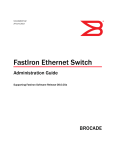
Survivable Branch Appliance
Because of the centralized deployment model of Microsoft Lync Server 2010, UC-enabled users at a remote site are
dependent on the servers in the data center for their communication and collaboration needs. Hence, they are
vulnerable to losing communication capabilities when the Wide-Area Network (WAN) is unavailable. Since “always
on” is a requirement for voice communications, it is imperative that the current UC solution continues to provide the
ability for branch users to make and receive calls, even when the network from the branch to the primary data center
is unavailable.
Survivable Branch Appliance (SBA) is a partner offering connecting the Microsoft Unified Communications
environment to the branch office PBX and/or the Public Switched Telephone Network (PSTN), while providing local
UC services and full branch office survivability. It comprises a single Windows Server application packaged in an
appliance form factor and loaded with Microsoft Lync Server 2010 software, which maintains branch office
communications even if the WAN connection to the data center becomes unavailable. With easy installation that can
be performed by a non-specialized network technician, centralized management from the data center, and seamless
operations in the event of a network outage, it is uniquely suited to the IT requirements of medium and large
branch offices.
Deploying Brocade Networks with Microsoft Lync Server 2010
6 of 52
DATA CENTER and CAMPUS NETWORKS
DEPLOYMENT GUIDE
Figure 2. Survivable branch appliance overview.
CALL ADMISSION CONTROL (CAC)
For IP-based real-time applications such as IP telephony, video, and application sharing, enterprise network
bandwidth is generally not considered a limiting factor in LAN environments. However, on WAN links between sites,
bandwidth is a finite resource. Ultimately, provisioning these links adequately is the correct approach. However, a
dependence on such network infrastructure upgrades initially can be a deployment hurdle. Upgrades to WAN links
are expensive and time-consuming. Many organizations need to experience a return on their investment in Unified
Communications firsthand before committing to WAN link upgrades. Therefore, to address UC traffic overflow, the
solution must provide an infrastructure that enables policy decisions to be made when real-time sessions are being
set up (whether or not sessions can actually be established).
When an influx of network traffic oversubscribes a WAN link, mechanisms such as queuing, buffering, and packet
drop resolve the congestion. The extra traffic is typically delayed until the network is decongested; or, if traffic is
dropped, the recipient times out and requests a retransmission. Network congestion cannot be resolved in this
manner with real-time traffic, because real-time traffic is sensitive to both latency and packet loss. This results in a
very poor quality of experience for end users. For real-time traffic, it is better to deny session requests under
congested conditions rather than allow sessions that result in a poor experience.
Bandwidth management is a solution that determines whether or not a real-time session can be established based
on the available bandwidth. The solution can also provide an alternative way to route the call when the preferred
route does not have the required bandwidth.
See the Appendix for configuration details.
QUALITY OF EXPERIENCE
Microsoft is focused on creating a Quality of Experience (QoE) based on optimizing and monitoring the user
experience. Microsoft does this by providing the following:
•
A comprehensive, user-focused approach to perceived quality. Microsoft UC QoE incorporates all
significant influencing parameters (network parameters and hardware, application, psychological, and
physical parameters) to optimize the user experience in a real-life context.
•
Intelligent, adaptive endpoints, including an advanced media stack. Microsoft UC is based on one of
the components of Microsoft Lync Server 2010, which provides the rich software that runs the
intelligent endpoints. It leverages underlying components, such as memory and CPU, to host
rich applications.
Deploying Brocade Networks with Microsoft Lync Server 2010
7 of 52
DATA CENTER and CAMPUS NETWORKS
•
DEPLOYMENT GUIDE
Real-time metrics of the actual experience. Microsoft takes metrics to a new level and goes beyond
monitoring network metrics such as packet loss, jitter, and latency. Microsoft monitors the QoE of all
users on all calls by using Microsoft Lync Server 2010 Monitoring Server, which collects comprehensive
metrics and aggregates them in a Call Detail Record (CDR).
NETWORK PERFORMANCE CONCERNS
Users determine the ultimate measure of the performance of any service. In the case of voice, that ultimate measure
is the subjective, in-context perception of voice quality by the listener. Such subjective perception incorporates and
reflects intelligibility, clarity, pleasantness of speech, absence of defects, and overall conformity—as perceived by the
listener. It goes beyond simple restitution of the actual literal content to also include appropriate perception of
speaker identity, emotions, intonation, and timbre, as well as the absence of annoying effects. In addition,
perception can be affected by an almost limitless variety of effects (delay, background noise and interference,
clipping, distortion, echo, pops and clicks, and signal cuts or drops).
One of the key areas that impacts voice quality in a VoIP solution is the network infrastructure. This paper provides a
detailed performance profile and network metrics thresholds for Microsoft Lync Server 2010, to help network
integrators define and deploy network best practices that guarantee good media quality.
Voice Quality on IP Networks
Internet Protocol (IP) networks provide best-effort data delivery by default. Best effort allows the complexity to stay in
the end-hosts, so that the network can remain relatively simple and economical. The fundamental principle of IP
networks is to leave complexity at the edges and keep the network core simple. This approach scales well, as
evidenced by the ability of the Internet to support its host count and traffic growth without any significant change in
operation. If and when network services requests from hosts exceed network capacity, the network does not abruptly
deny service to some users, but instead degrades performance progressively for all users by delaying the delivery of
packets—or even by dropping some packets.
The resulting variability in packet delivery does not adversely affect typical Internet applications (bursty and
sometimes bandwidth-intensive but not very delay-sensitive applications such as e-mail, file transfer, and Web
“elastic” applications) until very severe network performance degradation. If data packets arrive within a reasonable
amount of time and in almost any order, both the application and the user are satisfied. Delayed packets are likely to
eventually arrive, because applications typically use Transmission Control Protocol (TCP) at the transport layer. Of
course, TCP is a connection-oriented protocol with built-in adaptation mechanisms to ensure error-free data transfer,
ordered data transfer, diagnostic, re-request, and retransmission of lost packets, discarding of duplicate packets,
and flow control (also known as congestion throttling). This makes TCP “unfriendly” to real-time applications such as
VoIP applications.
Real-Time Effective Bandwidth
The measure of the bandwidth of an end-to-end network path that is actually available to applications or network
flows at a given point in time is generally expressed in kilobits per second (kbps), On a shared network, this measure
fluctuates under the influence of flows generated by other applications, flows of the same application between other
users, or up- and downtime of network elements and links.
Delay (or Latency)
Delay is the measure of the time required for a voice signal to traverse the network. It is called one-way delay when
measured endpoint to endpoint. Round-trip delay, also called Round Trip Time (RTT), is measured end-to-end and
back. Delay is generally expressed in milliseconds. Delay results from the time it takes the system or network to
digitize, encrypt where appropriate, packetize, transmit, route, buffer (often several times), depacketize, recombine,
decrypt, and restitute a voice signal.
These sources of IP telephony delay can be grouped into four main categories:
Deploying Brocade Networks with Microsoft Lync Server 2010
8 of 52
DATA CENTER and CAMPUS NETWORKS
DEPLOYMENT GUIDE
•
Processing delay includes the time required to collect a frame of voice samples before processing by
the speech encoder can occur—the actual process of encoding, encrypting if appropriate, packetizing
for transmission—and the corresponding reverse process on the receiving end, including the jitter
buffer used to compensate for varying packet arriving delay on the receiving end. The complete end-toend processing delay is often in the 60 ms to 120 ms range, when all of the contributing factors are
taken into account. The processing delay is essentially within a fixed range determined by the vendor’s
technology and implementation choices. Encoding and decoding might be repeated several times;
however, if there is any inline transcoding from one codec to another—for example, for hand-off
between networks—then accumulated processing delay can become disruptive.
•
Serialization delay is a fixed delay required to clock a voice or data frame onto a network interface,
placing the bits onto the wire for transmission. The delay varies based on the clocking speed of the
interface. A lower-speed circuit (such as a modem interface or smaller transmission circuit) has a
higher serialization delay than a higher-speed circuit. The delay can be quite significant on low-speed
links and occurs on every single link of a multihop network.
•
Network delay is mostly caused by inspecting, queuing, and buffering of packets, which can occur at
traffic shaping buffers (such as “leaky bucket” buffers), which are sometimes encountered at various
network ingress points or at various router hops encountered by the packet along the way. Network
delay on the Internet generally averages less than 40 ms when there is no major congestion. Typically,
an easy way to spot congestion is when network delays start to increase. It is good practice to create
alarms and alerts to detect such issues, so that you can quickly resolve the problem. Modernization of
routers has contributed to reducing this delay over time.
•
Propagation delay is the distance traveled by the packet, divided by the speed of signal propagation
(that is, the speed of light). Propagation delay on transcontinental routes is relatively small--typically
less than 40 ms—but propagation delay across complex intercontinental paths can be much greater.
This is especially true when satellite circuits are involved or on very long routes, such as Australia to
South Africa via Europe, which might incur up to 500 ms of one-way propagation delay.
The sum of these four delay components creates the total delay. The ITU-T has recommended 150 ms total one-way
delay (including endpoints) as the upper limit for “excellent” voice quality. Longer delays can be disruptive to the
conversation, with the risk of talkover effects and echo. When the one-way delay exceeds 250 ms, it is likely that
talkers will step over each other’s speech, which is known as step-over.
In the event of a transcontinental route with well-sized links, the total delay in non-congested conditions might be
70 ms (processing), plus 10 ms (serialization), plus 30 ms (network), plus 40 ms (propagation), which equals 150
ms total. Therefore, IP telephony calls frequently function where even small incremental delays could impact the
voice quality.
Network delay is the one component over which the system administrator has the most control. Network delay can
be reduced through a variety of network engineering means. However, the first priority of network delay engineering
is often avoidance of spikes and limitation of variability (that is, jitter) due to congestion—ahead of reduction in
normal delay. Of all the delay components, queuing at router hops is the most variable and unpredictable
component of overall delay, especially in situations of congestion. This makes it one of the areas in which Quality of
Service (QoS) techniques are most frequently used.
As network demands increase from voice and video, it is important to have network switches and routers that are
capable of scaling for these demands. Brocade switches give you the ability to scale to newer 10 Gigabit Ethernet
(GbE) technology, setting traffic rate limiting, and enabling end-to-end QoS. Network administrators need to carefully
assess their network trends over a period of time so that they can be sure of having adequate bandwidth during
peak times. In addition, Brocade IronView® Network Manager (INM) software can assist a network administrator in
analyzing the network and identifying hot spots.
Deploying Brocade Networks with Microsoft Lync Server 2010
9 of 52
DATA CENTER and CAMPUS NETWORKS
DEPLOYMENT GUIDE
Packet Loss
Packet loss occurs when packets are sent but not received at the final destination, due to a network problem. Packet
loss is the proportion (in percentages) of packets lost en route across the end-to-end network. Packets can be
designated as lost for a variety of reasons: actual errors in transmission, corruption, packets discarded from
overflowing buffers or for having stayed too long in the buffer, and packets arriving with too much delay or too much
out-of-order to still be usable. However, the main reason for packet loss is discarded packets in congested routers,
either because the buffer is full and overflowing, or due to methods such as Random Early Detection (RED) or
Weighted Early Random Detection (WRED), which proactively drop packets to avoid congestion.
Well-sized and well-managed IP backbones and LANs are designed to operate at better than a 0.5 percent packet
loss average. Packet loss on end-to-end Internet routes, however, can occasionally reach 5 percent or even 10
percent. Wi-Fi connections can experience well in excess of 10 percent loss.
Several factors make packet loss requirements somewhat variable. Even with the same average packet loss, the
manner in which the packets are lost influences voice quality:
•
There are two types of packet loss: random packet loss over time (single packets dropped every so
often during the call) and “bursty” packet loss (several contiguous packets lost in a short time window).
Losing 10 contiguous packets is worse than losing 10 packets evenly spaced over an hour.
•
Packet loss may also be more noticeable for larger voice payloads (that is, packets representing a
longer time sample) than for smaller ones, because more voice is lost in a larger payload.
•
Packet loss may be more tolerable for one codec over another, because some codecs have loss
concealment capabilities.
•
Packet loss requirements are tighter for tones (other than Dual-Tone Multi-Frequency (DTMF) signaling)
than for voice. The ear is less able to detect packet loss during speech (variable pitch) than during a
tone (consistent pitch).
•
Even small amounts of packet loss can greatly affect the ability of traditional TTY devices to work
properly, as well as transmission of faxes using the usual fax protocol T.30 over IP networks; standards
such as T.38 have been developed to reduce the impact of network issues on the reliability of faxing
over IP, but in practice they are not always supported, or the IP network may not be detected.
Jitter
Jitter is a measure of the time variability in the arrival of successive packets, generally expressed in milliseconds.
Jitter can result from packets taking different routes (for a variety of reasons, including load balancing or rerouting
due to congestion) and experiencing different propagation delays on those routes. Jitter can result from differences
in the effects of congestion, where some packets may have to wait for long buffer queues to be emptied, whereas
other packets may not. Jitter can also result in packets arriving out-of-order. Typically, the greater the network delay,
the greater the jitter, because each processing step is likely to add jitter.
The effects of jitter, if untreated, are similar to the effects of very severe packet loss at the endpoint, because
packets will arrive too late to be rendered to the end user. Therefore, the impact of jitter is reduced through the use
of a jitter buffer, located at the receiving end of the voice connection. The jitter buffer intentionally delays arriving
packets by more than the typical jitter value, in order to attempt to receive most jitter-affected packets, reorder
them, and retime them so that the end user hears the signal as intended. Unfortunately, jitter buffers introduce
incremental delay, which itself can negatively impact the experience. Therefore, jitter buffers typically contain only
about 20 to 40 ms of voice. Values of jitter in excess of the buffer length leads to packets being discarded.
By properly designing a network environment for peak loads, establishing proper QoS throughout the network, and
using Brocade Ethernet switches, you can reduce the amount of jitter. It is also important to properly provision the
network for adequate bandwidth so as to limit the amount of congestion, which can lead to increased jitter. When
deploying QoS, you should rate limit critical traffic so that other important data traffic can work in conjunction with
Deploying Brocade Networks with Microsoft Lync Server 2010
10 of 52
DATA CENTER and CAMPUS NETWORKS
DEPLOYMENT GUIDE
the Microsoft Lync Server 2010 environment if bandwidth is saturated. Fixed rate limiting allows you to specify the
maximum number of bytes a given port can send or receive, and it applies to all traffic on the rate-limited port.
REFERENCE ARCHITECTURE
Unified Communications, particularly High Definition (HD) video, is a significant driver of network traffic. Traditionally,
basic communications all had their own independent technologies, such as PBXs, telephones, and cell phones. In
many cases, these communication devices were not attached to the network. UC has now bridged that gap by
keeping people connected at all times. However, all that traffic is now sent over the network. Being able to prioritize
network traffic is very important to ensure that the most important data gets the higher priority.
Network designs vary depending on the size of your environment. Brocade has created and validated network
architectures for campus and data center environments to help simplify and speed up Microsoft Unified
Communications deployments.
Data Center
The Brocade Unified Communications reference architecture for data center environments, shown in Figure 3, is
based on a flattened two-tier network design and is comprised of the following:
•
Core layer
•
Ethernet fabric access layer
•
Hardware load balancing
Figure 3. Lync reference architecture for data center environments.
Deploying Brocade Networks with Microsoft Lync Server 2010
11 of 52
DATA CENTER and CAMPUS NETWORKS
DEPLOYMENT GUIDE
Core Layer
The core layer consists of high-speed, high-performance, and highly available switches, which connect the
aggregation layers and—in smaller environments—the access layer. In many cases, redundant 10 GbE links connect
the different layers, to provide the required bandwidth. The core layer is also known as the backbone; it is the Layer
3 domain that requires the maximum throughput, non-blocking, high-density, low-latency, and highly available design
architecture. That data center core is the source of packets that are forwarded to external entities, such as the WAN
and campus networks.
The core is one of the most important layers to consider in network design. If the core becomes a bottleneck, then all
attached devices behind it are affected as they try to reach external devices. As network traffic starts to proliferate,
having robust equipment with adequate bandwidth in the core to meet network traffic demand is of the utmost
importance. Typically in this layer QoS, Border Gateway Protocol (BGP), Open Shortest Path First (OSPF), and other
Layer 3 features are deployed.
Ethernet Fabric Access Layer
The access layer is the connection point for servers to “access” network services. The data center LAN typically
requires more resources, and in some cases 10 GbE is required to meet application requirements. Ethernet Fabric is
the key feature in this architecture, as it has collapsed three-tier architecture to two-tier architecture by eliminating
the aggregation layer.
Ethernet fabrics decrease the number of hops to create a flatter, faster architecture that is more efficient, while
remaining highly scalable and resilient. This innovative network advancement takes the most prized qualities of
Ethernet, adds much-needed intelligence, and delivers the services needed for today’s virtualized data center and
changing business requirements.
Since the access layer puts many demands on the network, scalability, high performance, reliability, Power over
Ethernet (PoE), and other advanced features are required. Layer 2 is typically deployed at this level, because it
allows a company to scale and servers and services to communicate more efficiently. The typical features configured
at this layer are Access Control Lists (ACLs), QoS, Class of Service (CoS)/Differentiated Services Code Point (DSCP),
Spanning Tree Protocol (STP), Link Layer Discovery Protocol-Media Endpoint Discovery (LLDP-MED), and PoE.
In some cases, network architects have deployed Ethernet fabrics in the access layer to take advantage of Ethernet
fabric benefits. These include:
•
Intelligent decision making
•
Reduced network complexity
•
Simplified management
•
Elasticity
•
Improved performance and scalability
To support this, Brocade VDX® switches incorporate Brocade VCS® Ethernet Fabric technology, which uses TRILL
(Transparent Interconnection of Lots of Links) frames in the data path. Further, VCS technology uses Brocade FSPF
(Fabric Shortest Path First), a well-proven link state routing protocol for Layer 2 networks, in the control plane. Link
state routing at Layer 2 is not “new,” unproven, or risky. The Brocade VCS Ethernet Fabric eliminates having to learn
L2 routing protocols, aka TRILL, multipath links, load balancing, Equal-Cost Multipath (ECMP) configuration, or lossless
Ethernet setup. These are handled automatically in a VCS Ethernet Fabric.
Brocade VCS technology can be updated with Intermediate System-to-Intermediate System (IS-IS) in the control
plane, which provides investment protection. A VCS Ethernet Fabric deployment is incremental and non-disruptive to
existing classic Ethernet environments. You can add it one server rack at a time, if you choose. Fabrics using FSPF
get large, and they are stable, resilient, self-healing, and scalable without reconfiguration of existing network
switches. Such fabrics are flatter, since most rely on core-edge topologies with very low path latency.
Deploying Brocade Networks with Microsoft Lync Server 2010
12 of 52
DATA CENTER and CAMPUS NETWORKS
DEPLOYMENT GUIDE
It is critical that you have reliable and deterministic switches that can quickly converge when outages occur. Outages
are inevitable, but having a solid design and robust Brocade switches keeps your network up and running without
affecting applications.
Hardware Load Balancing
Load balancing technology has become a technology of choice to improve the scalability, availability, and security of
IP applications. At this layer, Brocade ServerIron ADX hardware load balancers, with their networking and application
intelligence, provide rich features and the high performance required for building a massively scalable and highly
secure Microsoft Lync Server 2010 infrastructure. These features include the following:
•
Scalable Architecture that combines the leading processing performance with the highest density—the
only way to support advanced Application Delivery Controller (ADC) features and data center growth
•
Investment Protection with modular, easily upgradeable line cards, management cards, acceleration
cards, and switch fabrics to ensure ongoing value
•
Active/active and active/standby management modules—optional redundant modules for higher
availability and performance
•
Hardware-assisted, standards-based network monitoring for all application traffic flows—improving
manageability and security for network and server resources
•
Extensive and customizable service health check capabilities that monitor Layer 2, 3, 4, and 7
connectivity—along with service availability and server response time—to enable real-time problem
detection
•
Ability to remove failed servers and automatically redirect connections to new server
•
Disaster recovery and Global Server Load Balancing (GSLB) that distributes services transparently
across multiple sites and server farm locations, balancing traffic on a global basis while monitoring site,
server, and application health
•
SYN-Guard to protect server farms against multiple forms of Denial of Service (DoS) attacks, such as
TCPSYN and ACK attacks, by monitoring and tracking session flows
Microsoft recommends that you deploy a hardware-based load balancer in front of enterprise pools with multiple
Front End Servers, an array of Directors, and an array of Edge Servers. By incorporating Brocade load balancers in
front of the Microsoft Lync Server 2010 infrastructure, users are not disrupted when servers fail.
Campus
The Brocade Unified Communications reference architecture for campus environments, shown in Figure 4, is based
on a three-tier network design and is comprised of the following:
•
Core layer
•
Aggregation layer
•
Access layer
Deploying Brocade Networks with Microsoft Lync Server 2010
13 of 52
DATA CENTER and CAMPUS NETWORKS
DEPLOYMENT GUIDE
Figure 4. Lync reference architecture for campus environments.
Core Layer
The core layer consists of high-speed, high-performance, and highly available switches, which connect the
aggregation layers and, in smaller environments, the access layer. In many cases, redundant 10 GbE links connect
the different layers to provide the required bandwidth. The core layer is also known as the backbone; it is the Layer 3
domain that requires the maximum throughput, non-blocking, high density, low latency, and highly available design
architecture. That data center core is the source of packets forwarded to external entities, such as the WAN and
campus networks.
The core is one of the most important layers to consider in network design. If the core becomes a bottleneck, then all
attached devices behind it will be affected as they try to reach external devices. As network traffic starts to
proliferate, having robust equipment with adequate bandwidth in the core to meet network traffic demand is of the
utmost importance. Typically, in this layer QoS, BGP, OSPF, and other Layer 3 features are deployed.
Aggregation Layer
The aggregation layer aggregates multiple access layer switches and connects them to the campus or data center
core. Typically, devices such as firewalls and load balancers are located in the data center. In addition to the Layer 3
components listed above, this layer also deals with complex security, ACLs, scalability, QoS, STP, and so on. Typically,
each access and core switch is dual-connected to this layer for redundancy. In most cases, Layer 3 is connected to
the core, and Layer 2 is connected to the access layer.
Access Layer
The access layer is the connection point for notebooks, workstations, VoIP phones, WLAN access points, and servers
to “access” network services. The access layer is sometimes called the data center access layer or campus access
layer, but both provide the same functionality, that is, connecting devices to the network. Typically, the campus
Deploying Brocade Networks with Microsoft Lync Server 2010
14 of 52
DATA CENTER and CAMPUS NETWORKS
DEPLOYMENT GUIDE
access layer includes devices such as workstations, VoIP phones, and notebooks, which do not typically require the
same performance demands as servers require in the data center.
However, the campus LAN access layer requires PoE and PoE+ for IP phones. In most cases 1 GbE is sufficient to
meet most client demands.
Since the access layer puts many demands on the network, scalability, high performance, reliability, PoE, and other
advanced features are required. Layer 2 is typically deployed at this level, because it allows a company to scale and
servers and services to communicate more efficiently. The typical features configured at this layer are ACLs, QoS,
CoS/DSCP, STP, LLDP-MED, and PoE.
In some cases, network architects have deployed Layer 3 in the access layer to take advantage of Layer 3 benefits.
These include:
•
Server stability and application isolation
•
All uplinks available up to the ECMP maximum
•
Fast uplink convergence in the event of a failure
•
Reduction of broadcast domains
It is critical that you have reliable and deterministic switches that can quickly converge when outages occur. Outages
are inevitable, but having a solid design and robust Brocade switches keeps your network up and running without
affecting applications.
NETWORK SERVICES BEST PRACTICES FOR UNIFIED COMMUNICATIONS
Spanning Tree
Spanning Tree Protocol (STP), invented over 25 years ago, still plays a critical role in today’s network deployments.
STP is a Layer 2 protocol that eliminates redundant paths in a network. It discovers loops and then makes a decision
about which path will be used and which path will be shut down. How is this decision made? The root bridge is the
switch that decides. By default, the switch with the lowest Bridge ID (which is a combination of the switch priority
followed by the MAC address of the switch) becomes the root bridge. All Brocade switches have a default priority
of 32,678.
A disadvantage of STP is the reconfiguration and convergence time needed to recalculate optimal routes when a
switch fails. Typically, if the default Spanning Tree is used, this can take about a minute, depending on the network
size. During the convergence, applications go offline. Even though applications are built to handle a small amount of
downtime, a voice call would most likely get dropped during this convergence. Rapid Spanning Tree (RST, IEEE
802.1w) was invented to reduce the amount of time it takes to converge. RST is not based on any timer value.
Rather, it is based on the explicit handshakes between directly connected inter-switch ports to determine their role
as either a Designated Port or a Root Port. Hence, with port roles assigned sooner, the convergence time is less
than 500 ms.
NOTE: This rapid convergence does not occur on ports connected to shared media devices, such as hubs. To take
advantage of the rapid convergence provided by 802.1w, make sure to explicitly configure all point-to-point links
in a topology.
The Brocade implementation of 802.1w allows ports that are configured as edge ports to be present in an 802.1w
topology. Edge ports are ports of a bridge that are connected to workstations or computers. Edge ports do not
register any incoming Bridge Protocol Data Units (BPDU) activities. Edge ports assume Designated Port roles. Port
flapping does not cause any topology change events on edge ports, since 802.1w does not consider edge ports in
the Spanning Tree calculations.
When ports are configured for point-to-point, the switch knows that it is connected to another neighboring switch that
is also participating in RST. Configuring switches for point-to-point allows convergence to take place in about
Deploying Brocade Networks with Microsoft Lync Server 2010
15 of 52
DATA CENTER and CAMPUS NETWORKS
DEPLOYMENT GUIDE
500 ms, because ports that are participating in RST are known. Both voice and video can handle this amount of
downtime without affecting performance.
Brocade Layer 2/3 switches also support Per VLAN Spanning Tree (PVST). PVST is enabled in each VLAN as it is
enabled on a Layer 2 switch. In this case, each VLAN has its own instance of Spanning Tree and its own root bridge.
For example, if you have two VLANs, 10 and 20, VLAN 10 can have a different root bridge from VLAN 20.
To enable 802.1w for all ports in a port-based VLAN, enter commands such as these:
FastIron(config)#vlan 10
FastIron(config-vlan-10)#spanning-tree 802-1w
To configure a point-to-point port for 802.1w, enter commands such as these:
FastIron(config)#vlan 10
FastIron(config-vlan-10)#spanning-tree 802-1w e 9 admin-pt2pt-mac
To configure an edge port for 802.1w, enter commands such as these:
FastIron(config)#vlan 10
FastIron(config-vlan-10)#spanning-tree 802-1w e 9 admin-edge-port
We recommend that you use Rapid Spanning Tree Protocol (RSTP) with Microsoft Lync Server 2010. With
convergence time of about 500 ms, voice and video stay active with changes in the network, for example, when a
switch dies, computers are plugged into the network, or new switches are connected to network. If users are on a
voice call when a network switch dies with 802.1d Spanning Tree in place, the call is disconnected. Rapid Spanning
Tree (RPST), on the other hand, can converge fast enough such that Microsoft Lync Server 2010 can handle the brief
outage and the call is not dropped.
When configuring RSTP, be sure that you configure all the ports that are connected to other switches as a point-topoint connection. For all end devices, such as workstations, laptops, and VoIP phones, configure the switch as an
edge port.
VRRP and VRRP-e
Virtual Router Redundancy Protocol (VRRP) is a non-proprietary redundancy protocol designed to increase the
availability of the default gateways servicing hosts on the same subnet. This increased reliability is achieved by
advertising a “virtual router” as a default gateway to the hosts, instead of one physical router. Two or more physical
routers are then configured to represent the virtual router, with only one doing the actual routing at a given time. If
the current physical router that is routing the data on behalf of the virtual router fails, an arrangement is made for
another physical router to automatically replace it.
Traditionally, if a host default gateway goes offline, the network administrator needs to manually change the default
gateway, which is relatively simple if there are only a few hosts. But when there are hundreds or thousands of hosts,
it is an extremely complicated and cumbersome operation. Since both voice and video require the network, it is very
important that the network be robust and always online.
VRRP-e is a Brocade-enhanced version of VRRP that overcomes limitations in the standard protocol. With VRRP-e all
routers are backups for a given redundancy group, in which the router with the highest priority becomes master.
VRRP-e uses User Datagram Protocol (UDP) to send multicast “Hello” messages, and the VIP must be a unique
address on the same subnet on which VRRP-e is enabled.
VRRP-e, shown in Figure 5, is unlike VRRP in the following ways:
•
There is no “owner” router. You do not need to use an IP address configured on one of the Layer 3
Switches as the Virtual Router ID (VRID), which is the address you are backing up for redundancy. The
VRID is independent of the IP interfaces configured in the Layer 3 Switches. As a result, the protocol
does not have an “owner,” as VRRP does.
•
There is no restriction on which router can be the default master router. In VRRP, the “owner” (the
Layer 3 Switch on which the IP interface used for the VRID is configured) must be the default master.
Deploying Brocade Networks with Microsoft Lync Server 2010
16 of 52
DATA CENTER and CAMPUS NETWORKS
DEPLOYMENT GUIDE
Figure 5. Routers configured for VRRP-e to provide client redundancy.
To set up VRRP, enter the following commands on a Brocade Layer 3 switch.
Configure the owner:
Router1(config)#router vrrp
Router1(config)#inter e 1/6
Router1(config-if-1/6)#ip address 192.53.5.1
Router1(config-if-1/6)#ip vrrp vrid 1
Router1(config-if-1/6-vrid-1)#owner
Router1(config-if-1/6-vrid-1)#ip-address 192.53.5.1
Router1(config-if-1/6-vrid-1)#activate
Configure the backup:
Router2(config)#router vrrp
Router2(config)#inter e 1/5
Router2(config-if-1/5)#ip address 192.53.5.3
Router2(config-if-1/5)#ip vrrp vrid 1
Router2(config-if-1/5-vrid-1)#backup
Router2(config-if-1/5-vrid-1)#advertise backup
Router2(config-if-1/5-vrid-1)#ip-address 192.53.5.1
Router2(config-if-1/5-vrid-1)#activate
To set up VRRP-e, enter the following commands on each Layer 3 switch:
Router2(config)#router vrrp-extended
Router2(config)#inter e 1/5
Router2(config-if-1/5)#ip address 192.53.5.3
Router2(config-if-1/5)#ip vrrp-extended vrid 1
Router2(config-if-1/5-vrid-1)#backup
Router2(config-if-1/5-vrid-1)#advertise backup
Router2(config-if-1/5-vrid-1)#ip-address 192.53.5.254
Router2(config-if-1/5-vrid-1)#activate
Deploying Brocade Networks with Microsoft Lync Server 2010
17 of 52
DATA CENTER and CAMPUS NETWORKS
DEPLOYMENT GUIDE
Configure VRRP-e on default gateway routers for both the data center and campus LAN. Providing redundancy on
routers allows clients to seamlessly connect to another router within very little downtime. Note that if a voice call is in
place when the owner of the Virtual IP goes down, the phone call in most cases will drop.
Quality of Service (QoS)
Quality of Service (QoS) features are key to enabling a solid foundation for Microsoft Lync Server 2010. By Default,
Microsoft UC natively supports DiffServ through Differentiated Services Code Point (DSCP) marking by the endpoints,
which can easily be turned on or off and modified through Group Policies. A Microsoft TechNet entry
(http://technet.microsoft.com/en-us/library/dd441192(office.13).aspx) describes how to enable DSCP marking for
Microsoft Lync Server 2010. This includes: enabling QoS, installing the QoS Packet Scheduler on computers, and
verifying Group Policy settings on computers. QoS is honored by default on Brocade switches when the command
trust dscp is used.
QoS provides the ability to prioritize designated traffic over other traffic in a switch. The QoS associated with
synchronous traffic such as audio or video can be affected by delay, jitter, and packet loss. Microsoft Lync Server
2010 has been designed to work without any QoS, but when traffic demands increase and Service Level Agreements
(SLAs) are put in place, QoS is one of the most critical elements in the network. When QoS features are enabled on
Brocade switches, traffic is classified as it arrives at the switch and handled on the basis of configured priorities.
Traffic can be dropped, prioritized for guaranteed delivery, placed into a best-effort queue, or be subject to limited
delivery options. Traffic can also be controlled by leveraging rate limiting features that come with the Brocade
switches. Rate limiting limits the amount of bandwidth a certain type of traffic can use.
Classification is the process of selecting packets on which to perform QoS, reading the QoS information, and
assigning a priority to the packets. The classification process assigns a priority to packets as they enter the switch.
These priorities can be determined on the basis of information contained in the packet or assigned to the packet as
it arrives at the switch. Once a packet or traffic flow is classified, it is mapped to a forwarding priority queue. Packets
on Brocade devices are classified in up to eight traffic classes, with values from 0 through 7. Packets with higherpriority classifications are given precedence for forwarding. Typically, voice requires a classification between 4 and 6,
while video requires a classification in the range of 3 through 5, to ensure that enough resources are reserved. In
addition, you should configure rate limiting so that voice and video data does not saturate the link.
Configuration Options for QoS
The trust level in effect on an interface determines the type of QoS information the device uses for performing QoS.
The Brocade device establishes the trust level based on the configuration of certain features if the traffic is switched
or routed. The trust level can be one of the following:
•
Ingress port default priority. Not a recommended option for a Microsoft Lync Server 2010 environment,
because it assigns the entire port a priority and does not distinguish between data, voice, or video. In
addition, the port priority command never affects the DSCP value of the packet. It is used only to assign
internal prioritization for egress queueing and to assign the 802.1p value when a packet comes in
untagged without a tagged interface.
•
Static MAC address. Allows the user to control the priorities assigned to traffic based on the destination
MAC address. This is not also recommended, due to the overhead in management.
•
Access Control Lists. ACLs can prioritize traffic and mark it before sending it to the next hop. Since this
option is the most granular and suited for UC, it will be discussed in detail later.
•
Layer 2 Class of Service (CoS) value. This is the 802.1p priority value in the Ethernet frame. It can be a
value from 0 through 7. The 802.1p priority is also called the Class of Service.
Deploying Brocade Networks with Microsoft Lync Server 2010
18 of 52
DATA CENTER and CAMPUS NETWORKS
•
DEPLOYMENT GUIDE
Layer 3 Differentiated Service Code Point (DSCP). The value in the six most significant bits of the IP
packet header 8-bit DSCP field. It can be a value from 0 through 63. These values are described in
RFCs 2472 and 2475. The DSCP value is sometimes called the DiffServ value. The device
automatically maps a packet's DSCP value to a hardware-forwarding queue. Microsoft Lync Server
2010 supports this feature, and it is configured on each host. Typically, the host configuration is set up
through an Active Directory Group Policy so that it is configured only once, and then pushed out to all
the clients.
Given the different criteria, there are multiple possibilities for traffic classification within a stream of network traffic.
For this reason, the priority of packets must be resolved based on which criteria take precedence. Precedence for
Brocade switches follows the scheme illustrated in Figure 6.
Figure 6. QoS decision flow.
Once a packet is classified by one of the procedures mentioned, it is mapped to an internal forwarding queue. There
are eight queues, numbered 0 through 7. The internal forwarding priority maps to one of these eight queues. The
mapping between the internal priority and the forwarding queue cannot be changed.
Deploying Brocade Networks with Microsoft Lync Server 2010
19 of 52
DATA CENTER and CAMPUS NETWORKS
DEPLOYMENT GUIDE
Table 1. DSCP Relative to Cost of Service.
802.1p
DSCP
Brocade FCX
0
0–7
QoS p0
1
8 – 15
QoS p1
2
16 – 23
QoS p2
3
24 – 31
QoS p3
4
32 – 39
QoS p4
5
40 – 47
QoS p5
6
49 – 55
QoS p6
7
56 – 63
QoS p7
Access Control Lists: Layer 2 Codes
This option is the most granular of the three methods for prioritizing and/or marking traffic coming into the switch. All
of this is done using extended access lists.
Prioritizing Traffic
Prioritizing traffic using an access list is generally used to force the switch to honor DSCP or CoS. By leveraging ACLs,
you assign traffic that matches the ACL to a hardware-forwarding queue and re-mark the packets that match the ACL
with the 802.1p priority. In order to prioritize traffic, the administrator should identify which traffic needs to be
prioritized based on source/destination IP, port number, and so on, just like a regular ACL. Next, the traffic must
match either the incoming CoS or DSCP value before it is sent to the desired priority queue.
By default, on all Brocade switches, all untagged traffic is placed in the best-effort queue (QoS p0), which is the
lowest priority. If the packet is tagged, it is queued according to the CoS value in the 802.1p header. In order to
honor DSCP values, which Microsoft Lync Server 2010 uses, the endpoint (clients and servers) ports need to be
tagged. Given that voice and video are susceptible to latency, packet loss, and jitter, assigning a higher priority is
critical in maintaining your SLAs. However, it is not sufficient merely to set QoS on the switch to which the laptop,
desktop, or IP phone is connected. QoS needs to be configured throughout the network to allow end-to-end QoS.
Microsoft uses DSCP values for voice and video, allowing network administrators to assign different priorities for
each type of traffic. By default, Microsoft Lync Server 2010 uses DSCP 40 for the
IP QoS value and 0 for 802.1p voice. A value of 0 means DSCP is disabled and will automatically be placed in
queue0, which is best effort. That means that for networks honoring the DSCP marking, voice is prioritized higher
than video by default. By referring to Figure 6, a DSCP value of 40 is placed into the Brocade QoS queue5. Any
other traffic that is assigned a higher DSCP value, such as 56, is given precedence over voice. A network
administrator can easily change the priority of voice and video by changing the DSCP value within Group Policy or
802.1p priority marking.
Marking is the process of changing the packet’s QoS information (the 802.1p and DSCP information in a packet) for
the next hop. For example, for traffic coming from a device that does not support DiffServ, you can change the
packet’s IP Precedence value into a DSCP value before forwarding the packet. For example, with a simple switch
configuration you can have an endpoint that is marked with a DSCP value of 40 and assign it to a CoS of 7, which is
the highest priority. If you left the defaults, then the switch would follow the default CoS Map and assign it to a
hardware queue of 5.
Marking is optional and is disabled by default on the Brocade switches. Marking is performed using ACLs. When
marking is not used, the device still performs the mappings for scheduling the packet but leaves the packet’s QoS
values unchanged when the device forwards the packet.
Deploying Brocade Networks with Microsoft Lync Server 2010
20 of 52
DATA CENTER and CAMPUS NETWORKS
DEPLOYMENT GUIDE
Configuring QoS
• To enable DSCP, enter the this simple command, which is all that is necessary for configuration to
honor DSCP on Brocade switches:
FastIron(config-if-e1000-11)trust dscp
•
To change the DSCP value within Group Policy, refer to the Microsoft configuration guide. To assign
traffic that matches the ACL to a hardware forward queue and re-mark the packets that match the ACL
with the 802.p priority, use this command:
FastIron(config-if-e1000-11) access-list 101 permit ip any dscp-matching 46 802.1ppriority-marking 7
•
To change the DSCP internal forwarding priority mappings for all the DSCP ranges, enter commands
such as the following at the global CONFIG level of the Command Line Interface (CLI):
FastIron(config)#qos-tos map dscp-priority 48 to 7
This tells the switch that for any packet entering the switch with a DSCP value of 48, you should assign it to a
CoS (internal forwarding queue) value of 7 (the highest priority).
Scheduling
Scheduling is the process of mapping a packet to an internal forwarding queue based on its QoS information and
servicing the queues according to a mechanism.
QoS Queuing Methods
The following QoS queuing methods are supported in all IronWare releases for the Brocade FastIron® and TurboIron®
devices:
•
Weighted Round Robin (WRR). WRR ensures that all queues are serviced during each cycle. A
weighted fair queuing algorithm is used to rotate service among the eight queues on the Brocade
FastIron and TurboIron devices. The rotation is based on the weights you assign to each queue. This
method rotates service among the queues, forwarding a specific number of packets in one queue
before moving on to the next one. WRR is the default queuing method, and it uses a default set of
queue weights. The number of packets serviced during each visit to a queue depends on the
percentages you configure for the queues. The software automatically converts the percentages you
specify into weights for the queues.
Table 2. Default Minimum Bandwidth Percentages on Brocade Ethernet Switches Using WRR.
Queue
Without Jumbo Frames
With Jumbo Frames
QoS p7
75%
44%
QoS p6
7%
8%
QoS p5
3%
8%
QoS p4
3%
8%
QoS p3
3%
8%
QoS p2
3%
8%
QoS p1
3%
8%
QoS p0
3%
8%
These priorities can be changed. If you would like to change the recommended default configuration, please
refer to the configuration guide.
Deploying Brocade Networks with Microsoft Lync Server 2010
21 of 52
DATA CENTER and CAMPUS NETWORKS
•
DEPLOYMENT GUIDE
Strict Priority (SP). SP ensures service for high-priority traffic. The software assigns the maximum
weights to each queue, to cause the queuing mechanism to serve as many packets in one queue as
possible before moving to a lower queue. This method biases the queuing mechanism to favor the
higher queues over the lower queues.
For example, strict queuing processes as many packets as possible in QoS p3 before processing any packets in
QoS p2, then processes as many packets as possible in QoS p2 before processing any packets in QoS p1, and
so on.
•
Hybrid WRR and SP. Starting with Brocade software release FSX 02.2.00, an additional configurable
queuing mechanism combines both the strict priority and WRR mechanisms. The combined method
enables the Brocade device to give strict priority to delay-sensitive traffic, such as Voice and Video
traffic, and WRR priority to other traffic types.
By default, when you select the combined SP and WRR queuing method, the Brocade device assigns strict
priority to traffic in QoS p7 and QoS p6, and WRR priority to traffic in QoS p0 through QoS p5. Thus, the Brocade
device schedules traffic in queue 7 and queue 6 first, based on the strict priority queuing method. When there is
no traffic in queue 7 and queue 6, the device schedules the other queues in round-robin fashion from the
highest priority queue to the lowest priority queue.
Best Practices QoS
First, you should consult with upper management and get an understanding of how critical voice and video are. In
many cases, voice is very important and needs higher priority than most applications, but not all. One thing to be
sure of is that voice and video get a higher priority than day-to-day data traffic. For example, you want to prevent a
user who is watching YouTube to take up all the bandwidth and cause VOIP calls to be dropped.
Second, once you enable DSCP on the switch, any traffic that is marked with a DSCP value will follow the settings
according to Figure 6. By default all Windows clients use a DSCP value of 40 for voice and 0 for video. There are
three different options to change the DSCP value for the clients: Modify the DSCP value through an Active Directory
Group Policy, changing the registry on each client, or by remarking the packets on the Brocade switch. We
recommend that you change it by using a Group Policy, because you can configure it at one location and it will apply
to all the clients. If you make the change on the switch then it will require you make the same changes on all the
switches that see voice or video traffic. In many cases you can create custom scripts, or you can leverage Brocade
INM to distribute and apply custom QoS ACLs to multiple switches.
Rate Limiting
Each Brocade device supports line-rate rate limiting in hardware. The device creates entries in Content Addressable
Memory (CAM) for the rate limiting policies. The CAM entries enable the device to perform rate limiting in hardware
instead of sending the traffic to the CPU. The device sends the first packet in a given traffic flow to the CPU, which
creates a CAM entry—consisting of traffic source and destination addresses—for the traffic flow. The device uses the
CAM entry for rate limiting all the traffic in the same flow. A rate limiting CAM entry remains in the CAM for two
minutes before timing out.
Fixed rate limiting counts the number of bytes (for Brocade FastIron devices) or kilobits (for Brocade TurboIron
devices) that a port receives, in one-second intervals. If the number exceeds the maximum number that was
specified when the rate was configured, the port drops all further inbound packets for the duration of the one-second
interval. Once the one-second interval is complete, the port clears the counter and re-enables traffic.
To configure rate limiting on a Brocade FastIron port, enter commands such as:
FastIron(config)#interface ethernet 24
FastIron(config-if-e1000-24)#rate input fixed 500000
To configure ACL-based rate limiting, you should create individual traffic policies and then reference the traffic
policies in one or more ACL entries (also called clauses or statements). The traffic policies become effective on ports
to which the ACLs are bound.
Deploying Brocade Networks with Microsoft Lync Server 2010
22 of 52
DATA CENTER and CAMPUS NETWORKS
DEPLOYMENT GUIDE
Brocade devices support the following types of ACL-based rate limiting:
•
Fixed rate limiting. Enforces a strict bandwidth limit. The device forwards traffic that is within the limit,
but either drops all traffic that exceeds the limit, or forwards all traffic that exceeds the limit at the
lowest priority level, according to the action specified in the traffic policy.
•
Adaptive rate limiting. Enforces a flexible bandwidth limit that allows for bursts above the limit. You
can configure adaptive rate limiting to forward traffic, modify the IP precedence of traffic and forward it,
or drop traffic, based on whether the traffic is within the limit or exceeds the limit.
NOTE: Some Brocade switches do not support adaptive rate limiting, so consult the Release Notes to find out what
kind of rate limiting is supported.
To implement ACL-based fixed rate limiting, first create a traffic policy and then reference the policy in an extended
ACL statement. Lastly, bind the ACL to an interface. Steps are detailed below.
Create a traffic policy. Enter a command, such as:
FastIron(config)#traffic-policy TPD1 rate-limit fixed 100 exceed-action drop
Create an extended ACL entry or modify an existing extended ACL entry that references the traffic policy, for example:
FastIron(config)#access-list 101 permit ip host 210.10.12.2 any traffic-policy TPD1
Bind the ACL to an interface:
FastIron(config)#int e 5
FastIron(config-if-e5)#ip access-group 101 in
FastIron(config-if-e5)#exit
Link Aggregation
Link Aggregation (LAG) is the ability to configure multiple high-speed load sharing links between two Brocade Layer 2
switches or Layer 3 switches, or between a Brocade Layer 2 or Layer 3 switch and server.
In addition to enabling load sharing of traffic, LAG groups provide redundant, alternate paths for traffic if any of the
segments fail.
NOTE: Link aggregation is also referred to as a trunk, but not a VLAN Trunk. Cisco uses the term Etherchannel for
trunks, and Brocade uses the term LAGs.
There are two types of LAGs, static and dynamic (802.1ad Link aggregation).
Static LAGs are manually configured aggregate links that consist of multiple ports. Basically, when you configure a
static LAG, you configure the LAG once and then leave it alone. However, if you create a two-port LAG and then later
need to expand that LAG to four ports, you need to delete the existing LAG and create a new LAG. Switch LAGs are
designed to combine multiple physical ports into one logical pipe between Layer2/Layer3 switches. On all the newer
switches, 8 ports is the maximum number of ports per LAG group. Please refer to the configuration guide of the
switch you own to determine the number of ports per LAG group. The switch model you have in place determines the
way the LAG load balances traffic. Table 3 highlights the Brocade FCX and Brocade ICX™ load balancing methods:
Deploying Brocade Networks with Microsoft Lync Server 2010
23 of 52
DATA CENTER and CAMPUS NETWORKS
DEPLOYMENT GUIDE
Table 3. Load Balancing Methods for Brocade Trunks
Traffic Type
Load Balancing Method
L2 Bridged Non-IP
Source MAC, Destination MAC
L2 Bridged IPv4 TCP/UDP
Source IP, Destination IP, Source TCP/UDP Port, Destination TCP/UDP port
L2 Bridged IPv4 Non-TCP/UDP
Source IP, Destination IP
To configure a static LAG, enter the following commands:
FastIron(config)#trunk e 1/5 to 1/8
trunk will be created in next trunk deploy
FastIron(config)#write memory
FastIron(config)#trunk deploy
Dynamic Link Aggregation (802.1ad)
Brocade software supports the IEEE 802.3ad standard for link aggregation. This standard describes the Link
Aggregation Control Protocol (LACP), a mechanism for allowing ports on both sides of a redundant link to form a LAG
link (aggregate link), without the need for manual configuration of the ports into LAG groups.
When you enable link aggregation on a group of Brocade ports, the Brocade ports can negotiate with the ports at the
remote ends of the links to establish LAG groups.
The link aggregation feature automates LAG configuration but can coexist with the Brocade LAG group feature. Link
aggregation parameters do not interfere with LAG group parameters.
Link aggregation support is disabled by default. You can enable the feature on an individual port basis, in active or
passive mode:
•
Active mode. When you enable a port for active link aggregation, the Brocade port can exchange
standard LACP Data Unit (LACPDU) messages to negotiate LAG group configuration with the port on the
other side of the link. In addition, the Brocade port actively sends LACPDU messages on the link to
search for a link aggregation partner at the other end of the link, and it can initiate an LACPDU
exchange to negotiate link aggregation parameters with an appropriately configured remote port.
•
Passive mode. When you enable a port for passive link aggregation, the Brocade port can exchange
LACPDU messages with the port at the remote end of the link, but the Brocade port cannot search for a
link aggregation port or initiate negotiation of an aggregate link. Thus, the port at the remote end of the
link must initiate the LACPDU exchange.
To configure a dynamic LAG using default keys assigned by software:
FastIron(config)#interface ethernet 1/1
FastIron(config-if-e1000-1/1)#link-aggregate active
FastIron(config)#interface ethernet 1/2
FastIron(config-if-e1000-1/2)#link-aggregate active
To configure a dynamic LAG using an assigned unique key:
FastIron(config)#interface ethernet 1/1
FastIron(config-if-e1000-1/1)#link-aggregate active
FastIron(config)#interface ethernet 1/2
FastIron(config-if-e1000-1/2)#link-aggregate active
Deploying Brocade Networks with Microsoft Lync Server 2010
24 of 52
DATA CENTER and CAMPUS NETWORKS
DEPLOYMENT GUIDE
We recommend having at least 2 × 1 GbE ports per LAG at a minimum, to allow for redundancy when connecting
your access switch to your aggregate switch layer. Once your LAG has been created, analyze your network to make
sure that you do not have congestion on your LAGs. If congestion does occur, add more ports to the LAG to alleviate
the congestion. The same recommendations hold true if you have 10 GbE in place. Most Brocade switches have the
option for 10 GbE ports.
It is also recommended that you create a Network Interface Card (NIC) team on the Microsoft Lync Server
2010. The team creates redundancy if a NIC adapter fails. If possible, connect the NIC team to two
separate switches to eliminate a single point of failure.
When setting up a dynamic LAG, Brocade recommends that you disable or remove the cables from the ports
that you plan to enable for dynamic link aggregation. Doing so prevents the possibility that LACP will use a
partial configuration to talk to the other side of a link. A partial configuration does not cause errors, but
does sometimes require LACP to be disabled and re-enabled on both sides of the link to ensure that a full
configuration is used. It is easier to disable a port or remove its cable first. This applies to both active link
aggregation and passive link aggregation.
Figure 7. Example of multiple LAGs between access and aggregation layers.
High Availability for Load Balancing
A Microsoft Lync Server 2010 enterprise pool consisting of more than one Front End Server requires a hardware load
balancer. If you are deploying Standard Edition or a single Enterprise Edition Front End Server, a load balancer is not
required. A hardware load balancer is also required for arrays of Microsoft Lync Server 2010 Edge Servers or an
array of Standard Edition Servers configured as a Director. The requirements are summarized in Tables 4 and 5.
Table 4. Microsoft Recommended Hardware Load Balancer Requirements
Deployment
Load Balancer Requirement
A single Standard Edition Server
Load balancer not required
Enterprise pool with multiple Front End Servers
Hardware load balancer required
Array of Directors
Hardware load balancer required
Array of Edge Servers
Hardware load balancer required
Deploying Brocade Networks with Microsoft Lync Server 2010
25 of 52
DATA CENTER and CAMPUS NETWORKS
DEPLOYMENT GUIDE
Table 5. Ports Required, Load Balancer VIP Used by Enterprise Edition Front End Servers
Port Required
Port Use
5060
Client-to-server SIP communication over TCP
5061
Client-to-Front End Server SIP communication over TLS
SIP communication between Front End Servers over MTLS
5063 (TCP)
Used for incoming SIP listening requests for audio-visual (A/V) conferencing
5069 (TCP)
Used for Monitoring Server
135
To move users and perform other pool-level WMI operations over DCOM
Having no failover makes configuration and management somewhat easier, because you do not have to configure
and manage specific appliances. However, if one server fails, then your entire Unified Communications environment
is down, which means you have no VoIP, no IM, no presence, and/or no conferencing. Failover allows another
hardware load balancer to continually provide access to the servers in case of a failure. The different methods of
deploying a hardware load balancer are as follows:
•
Active-Hot Standby. One active hardware load balancer, with another hardware load balancer in
standby (supported only with switch code).
•
Active-Standby VIP. Both hardware load balancer switches can receive traffic, but only the Active VIP
handles the Layer 4–7 traffic. The other VIP is in standby mode and functions as a standby (supported
with router or switch code).
•
Active-Active. Both hardware load balancer switches are active for the same VIP, and the hardware
load balancer that receives the request is the one that services that request. In the case of a hardware
load balancer failure, the remaining hardware load balancer handles all requests (supported with
router or switch code).
Setting Up Active-Hot Standby Redundancy
In a typical hot standby configuration, one Brocade hardware load balancer is the active device and performs all the
Layer 2 switching as well as the Layer 4 server load balancing, while the other hardware load balancer monitors the
switching activities and remains in a hot standby role.
If the active hardware load balancer becomes unavailable, the standby hardware load balancer immediately
assumes the responsibilities of the unavailable hardware load balancer switch. The failover from the unavailable
hardware load balancer to the standby hardware load balancer happens transparently to users. Both hardware load
balancer switches share a common MAC address, which is known to the clients. Therefore, if a failover occurs, the
clients still know the hardware load balancer by the same MAC address. The active sessions that are running on the
clients continue, and the clients and routers do not need to re-ARP (Address Resolution Protocol) for the hardware
load balancer MAC address.
NOTE: All real servers must be connected to the Brocade ServerIron switches via a Layer 2 switch or NIC team
directly to the hardware load balancer switches (with the active NIC connected to the active hardware load balancer).
•
To configure port 1 on each hardware load balancer, enter the following command:
Hardware load balance (config)# server backup Ethernet 1 00e0.1234.1234 vlan-id 999
(This is the same primary MAC address used on both hardware load balancer switches.)
Deploying Brocade Networks with Microsoft Lync Server 2010
26 of 52
DATA CENTER and CAMPUS NETWORKS
•
DEPLOYMENT GUIDE
Configure VLAN 999, used for the sync connection between the hardware load balancer switches. Note
that you must turn off Spanning Tree.
Hardware load balance (config)# vlan 999
Hardware load balance (config)# untagged ethernet 1
Hardware load balance (config)# no spanning-tree
•
To set the number of minutes that the primary hardware load balancer waits before retaking over the
primary role after an outage, enter the following command (only on the primary hardware load
balancer; 5 minutes is the minimum value):
Hardware load balance# server backup-preference 5
•
To save the configuration to NVRAM, enter the following command:
Hardware load balance# write memory
Setting Up Active-Standby VIP Redundancy
The configuration uses an active and standby VIP for each VIP created. The active VIP and backup VIP are
determined by the sym-priority value associated with the VIP. The VIP with the highest sym-priority value is
considered the active VIP, and the others are considered standbys. The configuration does not require any changes
to Spanning Tree and does not require any sync connection between the hardware load balancer, as it uses the
network topology. Note that there cannot be a router hop between the two hardware load balancer switches, and
there must be Layer 2 connectivity.
The minimum configuration for Active VIP is as follows. Configure the VIP to use sym-priority:
Hardware load balance1 (config)# server virtual vip1 1.1.1.1
Hardware load balance1 (config)# sym-priority 10
The minimum configuration for Standby VIP is:
Hardware load balance2 (config)# server virtual vip1 1.1.1.1
Hardware load balance2 (config)# sym-priority 5
Setting Up Active-Active Redundancy
Active-active SLB uses session information to ensure that the same hardware load balancer load balances all
requests for a given VIP. The first hardware load balancer that receives a request for the VIP load balances the
request, creates a session table entry for the VIP, and sends the session information to the other hardware load
balancer. Both hardware load balancer switches in the configuration use the session information, so that the same
hardware load balancer is used for subsequent requests for the VIP.
In this example, hardware load balancer A and hardware load balancer B each have been configured to provide
active-active Symmetrical Server Load Balancing (SSLB) for the HTTP port on VIP1 and VIP2. The first hardware load
balancer to receive a request for an HTTP port on one of these VIPs load balances the request, creates session
entries for the VIP, and sends the session information to the other hardware load balancer. Both hardware load
balancer switches use the session information for the VIP to ensure that the same hardware load balancer load
balances subsequent requests for the same application port and VIP.
Either hardware load balancer can use session information to forward the server reply back to the client. For
example, if hardware load balancer A is the load balancer for a client request, and the server reply comes back
through hardware load balancer B, hardware load balancer B can use the session information received from
hardware load balancer A, through session synchronization, to perform the required address translations and send
the reply to the client. Hardware load balancer B does not need to forward the reply to hardware load balancer A for
address translation and forwarding.
Deploying Brocade Networks with Microsoft Lync Server 2010
27 of 52
DATA CENTER and CAMPUS NETWORKS
DEPLOYMENT GUIDE
The minimum configuration for active-active is VIP. Configure the VIP to use sym-active:
Hardware
Hardware
Hardware
Hardware
load
load
load
load
balance
balance
balance
balance
(config)# server virtual vip1 1.1.1.1
(config)# Port 80
(config)# sym-priority 10
(config)#sym-active
Configuring PoE for the Campus Network
Power over Ethernet is a core component for Unified Communications. Microsoft Lync Server 2010 endpoints do not
require PoE unless you are using IP phones, such as the Polycom CX700 IP phone. Polycom extends this Microsoft
Lync Server 2010 user experience with a broad portfolio of high-definition voice and video endpoints, including the
CX family of phones, the HDX family of video conferencing systems, and the RPX and TPX telepresence suites.
Brocade PoE devices provide Power over Ethernet, which is compliant with the standards described in the IEEE
802.3af specification for delivering in-line power. The 802.3af specification defines the standard for delivering power
over existing network cabling infrastructure and enabling multicast-enabled full streaming audio and video
applications for converged services, such as VoIP, WLAN access points, IP surveillance cameras, and other IP
technology devices. PoE technology eliminates the need for an electrical outlet and dedicated UPS near IP-powered
devices. With power sourcing devices such as the Brocade FastIron® CX, power is consolidated and centralized in
wiring closets, improving the reliability and resiliency of the network. Because PoE can provide power over an
Ethernet cable, power is continuous, even if the main power source fails.
To enable a port to receive in-line power for 802.3af-compliant and non-compliant power consuming devices, enter
commands such as the following:
FastIron#config t
FastIron(config)#interface e 1/1
FastIron(config-if-e1000-1/1)#inline power
After these commands are run, the console displays the following message:
FastIron(config-if-e1000-1/1)#PoE Info: Power enabled on port 1/1.
When PoE is enabled on a port to which a power-consuming device is attached, then by default the Brocade
PoE device supplies 15.4 watts of power at the RJ45 jack, minus any power loss through the cables. For example, a
PoE port with a default maximum power level of 15.4 watts receives a maximum of 12.95 watts of power after 2.45
watts of power loss through the cable.
NOTE: It is best practice to enable PoE on all ports.
Deploying Brocade Networks with Microsoft Lync Server 2010
28 of 52
DATA CENTER and CAMPUS NETWORKS
DEPLOYMENT GUIDE
CASE STUDY: FABRIKAM SPORTS
Consider the example of a fictional, but representative, global corporation called Fabrikam Sports. Fabrikam is a
well-known, well-established clothing manufacturer of high-end sports apparel. The recent success of the company
has put a lot of pressure on its IT organization to scale rapidly. Like all growing organizations, Fabrikam has deployed
many different communications technologies along the way. These communications technologies have included
telephony systems, conferencing and collaboration tools, and e-mail. However, a different administrator was
required for each technology to keep up with a rapidly growing mobile workforce. The company realized that in its
current situation, it would be unable to scale to meet projected growth.
Fabrikam maintains offices in the U.S. and is currently planning to open offices around the world. Clothing is
manufactured in Texas, designers are based in San Francisco, a regional sales office is located in New York, and
headquarters are in Seattle. There is currently a total of 4,500 employees worldwide, and this number is growing
rapidly—there are over 200 sales representatives in the U.S. and over 50 sales representatives divided between
Europe and Asia. As a result, the company is facing many challenges in its ability to collaborate effectively and in real
time. Fabrikam Sports is looking for a technology that centralizes VoIP, presence (the reporting of users online),
mobile client connectivity, and conferencing, so that the company can streamline communications to dramatically
reduce overall costs.
Currently, in each office Fabrikam has a PBX with two Primary Rate Interfaces (PRIs) out to the PSTN and a separate
hardware platform for video conferencing, and all employees use their own personal accounts for Instant Messaging
(using Yahoo, MSN, AOL, and so on). The IT department wants to unify these platforms so that they can easily
manage the different technologies in one framework. Microsoft Lync Server 2010 has been chosen, because it
offers a complete set of UC tools and easily integrates with Fabrikam’s current implementation of Microsoft
Exchange Server 2010.
By implementing these solutions, Microsoft Lync Server 2010 lowers Total Cost of Ownership (TCO) by reducing the
following costs:
•
Hardware costs. Historically, every office needed its own PBX equipment and its own trunk
to the PSTN. Every time an office came online, Fabrikam had to buy a PBX, a dedicated LAG from the
PSTN, and a phone plan. With Microsoft Lync Server 2010, Fabrikam now has centralized
communications to the existing IP network, which largely eliminates hardware costs.
•
Maintenance costs. Each Fabrikam office had its own dedicated PBX; however, each was from a
different manufacturer. This was costly, because administrators found it difficult to maintain and
upgrade all the different systems. Typically, IT had to place a tech support call in to each vendor for
help with the upgrade process. In addition, if a user moved or relocated to another office, the
administrator had to manually reconfigure the PBX. With Microsoft Lync Server 2010, a user can be
located anywhere and still be connected, because the communication is software-based.
•
Cost of long-distance phone calls. Fabrikam was spending a lot of money on long-distance calling to
both customers and mobile workers. To reduce some of the costs, mobile workers were using calling
cards. In addition, it took a full-time employee just to manage the calling plans for all the offices.
Microsoft Lync Server 2010 offers an IP-based system to make on-net calls possible at essentially no
cost. Additionally, if off-network calls are made, Microsoft Lync Server 2010 automatically routes calls
as cheaply as possible.
•
High Availability. Fabrikam has decided to place a Survivable Branch Appliance (SBA) at sites in Austin
and San Francisco to increase the availability of Microsoft Communicator 2010. The SBA allows remote
users to use the local SBA as a Front End Server instead of traversing the WAN to leverage the Front
End Servers at headquarters. Even if the WAN connection between the branch office and headquarters
goes down, users are not affected and can IM their colleagues in the local office and also place
outgoing calls.
In order for Fabrikam to deliver Microsoft Lync Server 2010, a sound network infrastructure was required. The
networking team realized that Unified Communications was going to create greater demands due to voice, video,
Deploying Brocade Networks with Microsoft Lync Server 2010
29 of 52
DATA CENTER and CAMPUS NETWORKS
DEPLOYMENT GUIDE
and conferencing converging onto the network. Fabrikam has already standardized on Brocade Ethernet products for
its load balancing, switching, and routing needs, because the Brocade products deliver the highest performance,
lowest price, and lowest power consumptions on the market.
Goals
For a successful deployment, the Fabrikam network team wanted to verify that the network was properly configured
to meet the demands of Microsoft Lync Server 2010. The team decided to implement IM, presence, VoIP, and video.
The CEO and management team decided that voice and video were the most critical application within the company.
Given this, the team needed to put QoS in place to give priority over all other applications.
In addition, the network team wanted to be sure that its network was robust at all layers of the network: access,
aggregate, and core. By leveraging a tiered network architecture, Fabrikam can easily integrate Microsoft Lync Server
2010 non-disruptively in the network.
The network team set forth the following goals.
•
Three-tiered network architecture for both the campus and data center LAN at the headquarters and in
the San Francisco and Austin offices. This means placing the following installations:
o
Brocade FCX and ICX enabled with PoE+ at the campus LAN access layer
o
Brocade FastIron® SX at the campus aggregation layer
o
Brocade VDX, Brocade ServerIron® ADX, and Brocade SAN in the data center Brocade NetIron®
MLX® at the network core
•
Place 10 GbE 802.1ad LAGs between each switch and the upper layer (see Figures 7 and 8). This
provides complete redundancy in each layer.
•
Provide complete redundancy in each layer.
•
Purchase SIP (Session Initiation Protocol) LAGs from the ISP that allow the company to take advantage
of all the features of Microsoft Lync Server 2010 across all offices and mobile users.
•
Honor the QoS configured on all switches. Create an 802.1p marking ACLs to change the default DSCP
value assigned by Microsoft Lync Server 2010, to provide higher priority for voice and video. In
addition, configure rate limiting so that voice and video do not take up all the bandwidth.
•
Deploy Rapid Spanning Tree on each VLAN.
•
Load balance Microsoft Lync Server 2010 Front-End, Edge, and Directory Servers to increase
performance and security and to provide redundancy if any one of the Front End Servers fails.
•
Ensure that each office experiences a Mean Opinion Score (MOS) that is greater than 3.5 in all cases.
Network Architecture
The Fabrikam network team took a look at the requirements for Microsoft Lync Server 2010 and deployed
the following network architecture.
Core
The core is the most critical element in the network. Since San Jose, Seattle, and Austin are the largest offices,
Fabrikam has standardized using the Brocade NetIron MLX at the core for both the data center and campus LAN.
The Brocade NetIron MLX Series of advanced routers provides industry-leading 10 GbE and 1 GbE port density, wirespeed performance, and a rich set of IPv4, IPv6, Multiprotocol Label Switching (MPLS), Virtual Private LAN Services
(VPLS), multi-VRF (Virtual Routing and Forwarding), and Carrier Ethernet capabilities.
Deploying Brocade Networks with Microsoft Lync Server 2010
30 of 52
DATA CENTER and CAMPUS NETWORKS
DEPLOYMENT GUIDE
In addition, the Brocade NetIron MLX switches will be configured for only Layer 3 and will include features such as
OSPF, LACP LAGs, and VRRP-e. Each Brocade NetIron MLX will have two separate LAGs with a 2 × 10 GbE LACP LAG
to each aggregation switch. OSPF will maintain the link state information and provide redundancy in case of a switch
failure.
The Fabrikam New York sales office will use the Brocade FastIron Super X as the core. Due to the size of the office,
there is no separation of the data center and campus LAN. The Brocade FastIron Super X will be running Layer 3 with
all the same functions as the Brocade NetIron MLX.
The features included in the core to meet the demands of Microsoft Lync Server 2010 are as follows:
•
VRRP-e. This feature provides redundancy to routers with a LAN. Clients configure their default gateway
to the virtual router ID. This enables the client to maintain connectivity if a Brocade NetIron MLX
goes offline.
•
OSPF. The core routers need to be configured with OSPF for both internal and external routes. OSPF
gathers link state information from available routers and constructs a topology map of the network.
•
LAGs. The team decided to enable two separate LAGs. Each LAG will be a 2 × 10 GbE LACP LAG to
adjacent switches. By enabling the LAG, you can effectively provide 20 GbE of bandwidth between the
switches and provide redundancy if one or more ports goes offline.
•
QoS ACLs. Ensure that the QoS enabled at the access layer is maintained.
Aggregation
The aggregation layer is also very important in the network architecture, because it is the bridge between the data
center and campus LAN access and core layers. The main Fabrikam offices (San Jose, Seattle, and Austin) will use
the Brocade FastIron Super X as aggregation switches running Layer 3 OSPF up to the core and Layer 2 to the
access layer. Brocade FastIron Super X switches will include the Layer 3 features OSPF, LACP, and QoS. In addition,
they will have the following Layer 2 features:
•
VLAN. Fabrikam has decided to create separate VLANs for the different types of traffic. Client data
traffic, which includes Live Communications Manager traffic, will run on VLAN 10. Pure VoIP traffic,
which includes Polycom CX600 phones, will run on VLAN 20. Monitoring traffic will run on VLAN 30.
•
Traffic Rate Limiting. Even though Fabrikam has made voice and video a higher priority than typical
day-to-day traffic, it wants to be sure that video does not consume all the available bandwidth. Since
video, especially HD video, is bandwidth-demanding, Fabrikam has decided to limit the bandwidth
available to video use traffic shaping on the Brocade switches. However, if video does reach its allotted
bandwidth, and there is additional bandwidth available, then the Brocade switches will apply best effort
to the remaining packets.
•
Per VLAN Spanning Tree. Per VLAN Spanning Tree will be enabled on each VLAN. PVST allows each
VLAN to have its own Root Bridge. This ensures that if any switch goes offline, alternate paths are
available for the traffic flow. On each interface that is connected to an adjacent switch, use the
command admin-pt2pt-mac to decrease the convergence time of Spanning Tree to a few milliseconds
and allow voice and video calls to maintain state if a switch goes offline.
•
QoS ACLs. Ensure that the QoS enabled at the access layer is maintained.
The aggregation layer is also the layer to which load balancers and firewalls are connected.
Access
The access layer is the layer in which the endpoints connect laptops and desktops from the campus LAN and servers
from the data center. Fabrikam has decided to use 48-port Brocade FCX switches with PoE at the access layer for
the campus LAN and 48-port Brocade FCX switches without PoE for the data center. The Brocade FCX is designed for
wire-speed and non-blocking performance.
Deploying Brocade Networks with Microsoft Lync Server 2010
31 of 52
DATA CENTER and CAMPUS NETWORKS
DEPLOYMENT GUIDE
Utilizing built-in 16 Gigabits per second (Gbps) stacking ports and Brocade IronStack® technology, Fabrikam will
have the flexibility to stack up to eight switches into a single logical switch with up to 384 ports. In addition, PoE
models support the emerging Power over Ethernet Plus (PoE+) standard to deliver up to
30 watts of power to edge devices, enabling next-generation campus applications. The access layer will have two
separate LAGs to two different aggregation switches to provide redundancy and use leverage Multiple Spanning Tree
Protocol (MSTP).
At this layer, QoS is applied to actual voice and video packets.
•
QoS ACLs. Access Control Lists will need to be created to map the DSCP values to the appropriate cost
of service value. Fabrikam management wants to ensure that voice has one of the highest priorities,
because they cannot afford dropped calls. However, IT wants to be sure that other priorities such as
alerts, control traffic, and Active Directory have a higher priority than all other traffic. Fabrikam has
decided to configure the appropriate DSCP values as follows:
–
Video: DSCP value of 30, CoS 3
–
Voice: DSCP value of 40, CoS 5
–
Control Traffic: DSCP value of 48, CoS 7
Figure 8. Fabrikam reference architecture.
Load Balancers
Hardware load balancers are one of the most critical elements when deploying Microsoft Lync Server 2010. For the
Fabrikam installation, Brocade ServerIron ADX hardware load balancers were placed in front of the Front-End,
Director, and Edge Servers, providing a single user connection point (VIP) to an abundance of servers in the
background. The Brocade ServerIron ADX hardware load balancer ensures that traffic is properly balanced among all
the real servers and that traffic is not sent to a failed server. The Brocade ServerIron ADX hardware load balancer
Deploying Brocade Networks with Microsoft Lync Server 2010
32 of 52
DATA CENTER and CAMPUS NETWORKS
DEPLOYMENT GUIDE
provides DoS security to the servers by ensuring that traffic from a hacker will be placed into the “bit bucket” and not
forwarded to the real servers. Note that the Brocade ServerIron ADX is not a single point of failure, as it can be
configured with another Brocade ServerIron ADX to provide different types of redundancy, as discussed earlier in this
document.
Latency
Latency is a critical element that needs to be taken into account when designing a network. Fabrikam wants to be
sure that latency will not degrade the performance of Microsoft Lync Server 2010. Between each site the latency
was measured as follows:
•
Between San Jose and New York: 50 ms
•
Between San Jose and Austin: 25 ms
•
Between San Jose and Seattle: 5 ms
Fabrikam has implemented certain features in the Brocade switches to help deal with latency and jitter by providing
QoS, rate limiting, and enough bandwidth in the switches themselves—however, none of these features can
overcome the challenges of distance. Fabrikam has set up an SLA with the ISP such that latency will not exceed
100 ms.
Figure 9. Logical hardware load balancing Microsoft Lync Server 2010 servers.
Deploying Brocade Networks with Microsoft Lync Server 2010
33 of 52
DATA CENTER and CAMPUS NETWORKS
DEPLOYMENT GUIDE
Server Architecture
Given the size of the company, Fabrikam has decided to centralize the deployment of the Microsoft Lync Server
2010 servers. The company wants to make sure that full redundancy is built into all layers of the Microsoft Lync
Server 2010 deployment to ensure no single point of network failure. The company has settled on this deployment:
•
Demilitarized Zone (DMZ)
–
•
Edge Servers: Two Edge Servers are deployed to service external clients residing outside the
internal network. Microsoft Lync Server 2010 Edge Servers provide multiple roles such as an
Access Edge Server, Web Conferencing Edge Server, A/V Edge Server, and Reverse Proxy Server. If
demands increase on these servers, then these roles will be split into separate servers. The Edge
Server sits behind the Brocade ServerIron ADX hardware load balancer to provide redundancy,
security, and reliability.
Internal
–
Director Servers: Director Servers are used for external user authentication and to pass requests
to the Front End Servers. The Director Servers are also load balanced to distribute the load and
provide redundancy.
–
Front End Servers: Fabrikam has decided to consolidate many roles on the Front End Servers,
including voice, IM, presence, and conferencing. If the Front End Servers become overburdened,
then these roles can be moved to dedicated servers.
–
Monitoring Server: Fabrikam has decided to install a single Monitoring Server that collects metrics
from the Microsoft Lync Server 2010 clients, to provide a QoE score.
–
Survivable Branch Appliance: Fabrikam has decided to place SBAs in San Francisco and Austin to
provide local authentication and provide higher availability.
Summary
Leveraging both Brocade products and Microsoft Lync Server 2010, Fabrikam met and exceeded all of their initial
goals. ROI benefits were seen immediately and, at the same time, end-user satisfaction has risen to a new level due
to the performance enhancements of Microsoft Lync Server 2010 and the Brocade infrastructure. End users
embraced the fact that Microsoft Lync Server 2010 simplified communications by blending services that used to be
managed separately into a single platform, providing connection to anyone at any time over any type of device.
The network team was delighted to see how easy it was to configure and set up a Brocade environment. They feel
confident knowing that the network can scale to meet the needs of their most demanding users. The Brocade
networking products exceeded the network performance standards required for an optimal Microsoft Lync Server
2010 experience and have proven to integrate seamlessly at all levels in the network.
Deploying Brocade Networks with Microsoft Lync Server 2010
34 of 52
DATA CENTER and CAMPUS NETWORKS
DEPLOYMENT GUIDE
MICROSOFT LYNC SERVER 2010 QUALIFICATION
This section describes the test configuration and test cases used to test interoperability between Brocade
networking products and Microsoft Lync Server 2010. Microsoft Unified Communications solutions use the power of
software to streamline communication. Microsoft Lync Server 2010, one of the cornerstones of the Microsoft UC
solution, is the platform for presence, instant messaging, conferencing, and enterprise voice for businesses around
the world.
Brocade offers a complete line of enterprise and service provider Ethernet switches, Ethernet routers, application
management, and network-wide security products. With industry-leading features, performance, reliability, and
scalability capabilities, Brocade products enable network convergence and secure network infrastructures to support
advanced data, voice, and video applications. The complete Brocade product portfolio enables end-to-end
networking from the edge to the core of today's networking infrastructures.
Test Goals
The Microsoft Lync Server 2010 network certification tested both voice and video over distances using Brocade
Ethernet switches and load balancers. The objectives were as follows:
•
Availability. One of the primary responsibilities of the Brocade hardware load balancer is to ensure
application availability through application health checks, resilient Layer 2/3 mechanisms, and internal
High Availability (HA).
•
Performance. Given the different latencies and packet loss between remote offices, users in remote
offices should still be able to perform voice and video calls without call drops, echoes, or talkovers.
•
Optimization. To optimize traffic, QoS ACLs were applied to both voice and video traffic, giving it higher
priority over other traffic. In addition, traffic rate limiting was applied to video.
Network Design
Figure 10 shows the network topology used for testing. An expanded deployment model was used to separate the
Microsoft Lync Server 2010 roles.
Figure 10. Microsoft Lync Server 2010 testing with Brocade Ethernet switches.
Deploying Brocade Networks with Microsoft Lync Server 2010
35 of 52
DATA CENTER and CAMPUS NETWORKS
DEPLOYMENT GUIDE
Headquarters
All the main Microsoft Lync Server 2010 servers were located at the headquarters, which included two Front End
Servers, two Director Servers, one Monitoring Server, and two Edge Servers. The two Edge Servers were placed into
the DMZ that serviced external clients connecting to the environment.
Microsoft core services, such as Active Directory and SQL Server, were also deployed at the headquarters. SQL
Server 2008 was configured using Microsoft Clustering Services to provide fault tolerance. The SQL Server 2008
database resided on an enterprise-class HP storage system. The SQL Server 2008 servers used Brocade Fibre
Channel (FC) Host Bus Adapters (HBAs) connected to a Brocade 5100 Switch. The infrastructure included Brocade
FastIron SX 800 Switches for Layer 2/3 services and a pair of Brocade hardware load balancer ServerIron ADX 1000
switches for hardware-based load balancing for the Edge Servers, Front End Servers, and Director Servers.
ISP
The Brocade MLX was used to simulate an Internet Service Provider (ISP). A Brocade FastIron SX was configured for
OSPF, to direct traffic to the appropriate site.
Branch Offices
Each branch office used a Brocade FCX for both Layers 2 and 3. In addition, each site was configured for a different
latency based on the distance from the headquarters. The following link was leveraged for estimated latencies
between each site. A 15 percent packet loss between the San Jose and New York sites simulated the extreme end of
packet loss. In most cases, 5 percent is the maximum packet loss experienced with a reliable service provider. Even
with a 15 percent packet loss, the quality of voice and High Definition video calls were not affected. However, video
is more susceptible to latency and will get out of sync between the voice and video. In addition, SBAs were placed in
Austin and San Francisco.
The following were the latencies and packet loss between the sites. Different packet losses were simulated to
observe the effect on calls.
•
San Jose to New York: 50 ms latency with 0–15 percent packet loss
•
•
San Jose to Austin: 25 ms latency with 0–15 percent packet loss
San Jose to Seattle: 5 ms latency with 0–15 percent packet loss
Hardware and Equipment
Server Roles
• FE-1: Front-End Microsoft Lync Server 2010 server
• FE-2: Front-End Microsoft Lync Server 2010 server
• Dir-1: Director Microsoft Lync Server 2010 server
• Dir-2 Director Microsoft Lync Server 2010 server
• Edge-1: Edge Microsoft Lync Server 2010 server
• Edge-2 Edge Microsoft Lync Server 2010 server
• Mon-1: Monitoring Microsoft Lync Server 2010 server
• SQL-1: Back End SQL Server
• SQL-2 Back End SQL Server
• DC1: Domain Controller
• AUSBOA: Microsoft Lync Server 2010SBA
• SFBOA: Microsoft Lync Server 2010SBA
Software Requirements
• All the servers: Microsoft Windows 2008 R2 operating system
• Microsoft SQL Server 2008: SQL Server instances, using Microsoft Clustering Services
• Microsoft Lync Server 2010 with the most recent patches at the time of writing
Deploying Brocade Networks with Microsoft Lync Server 2010
36 of 52
DATA CENTER and CAMPUS NETWORKS
DEPLOYMENT GUIDE
Hardware Requirements
• Campus and Data Center Core Switches – Brocade MLX
• Campus Aggregation Switches – Brocade SX 800
• Campus / Branch Access Switch – Brocade ICX
• Data Center Ethernet Fabric – Brocade VDX
• Data Center Storage Fabric – Brocade 5120
• Data Center Hardware Load Balancer – Brocade ServerIron ADX 1000
• Servers: HP DL-380 with 4 GB RAM, 146 GB hard drive, Windows 2008 64 bit
Test Approach
When a call is assigned a MOS score greater than 3.5, based on the Microsoft Quality of Experience monitoring role,
specifically the Listening Quality (LQ) MOS scale, it is considered a successful call.
Table 6. Listening Quality MOS scale
MOS Score
Quality of Speech
5
Excellent
4
Good
3
Fair
2
Poor
1
Bad
The test consisted of the three branch offices with a varying latency and different amounts of packet loss. To
simulate the latency and packet loss, a Shunra WAN simulator was used. To simulate I/O, Iometer software (from the
Open Source Development Lab [OSDL]) was used on the client side to saturate the link.
On the client side, both Microsoft Qualified soft clients (headsets) and Polycom CX600 IP phones optimized for
Microsoft Office Communicator 2010 were used to place the calls. The Polycom CX 600 provides a high-quality
handset for crystal-clear, natural conversations without echoes or feedback, all at a very low cost.
Microsoft Lync Server 2010 Monitoring Server was used to provide the key metrics that measured the success of the
tests. These metrics included average jitter, average delay, average packet loss, and average MOS score, as
summarized in Table 7. Anything with a MOS score of less than 3.5 was not acceptable. Note that a score of 4 or
above is considered “toll quality,” and most of the scores in this testing were toll quality. In addition to the results
provided by the Monitoring Server, subjective evaluation was also used to judge the sound quality and the voice
quality. When the tests were conducted, the quality of all calls was considered clear with no feedback, echoes or
long pauses. In addition, the quality of the call for both voice and video were better than Microsoft Communication
Server 2010, especially under extreme conditions.
Deploying Brocade Networks with Microsoft Lync Server 2010
37 of 52
DATA CENTER and CAMPUS NETWORKS
DEPLOYMENT GUIDE
Figure 11 Network with associated latencies.
Voice calls were made using (1) the soft clients, (2) the Polycom CX700 phones, and (3) High Definition
video calls:
1.
From Seattle to all the remote sites
2.
From San Francisco to all the remote sites
3.
From New York to all the remote sites
4.
From Austin to all the remote sites
5.
Three conference calls among all the sites using (a) soft clients, (b) all Polycom phones, and
(c) all soft clients plus Polycom phones
Test Results
The key metric in determining the success of the tests was the Mean Opinion Score (MOS). In most cases the
average MOS score was greater than 4; that is, between good and excellent. As expected, when the packet loss
was increased above 25 percent across the high-latency links, call quality started to diminish, which reduced the
MOS score. However, when packet loss was less than 25 percent, call quality was clear without any type of
noticeable degradation. The Polycom CX600 produced a better voice experience than the soft clients, due to the
hardware offloading.
HD video quality saw the biggest impact when packet loss was greater than 15 percent. When tests were conducted
with 10 percent packet loss and 55 ms latency, the HD video experience was very good, with a MOS score of 3.93.
The boundary for Microsoft Lync Server 2010 was 5 percent packet loss, thus a big improvement was seen for
HD video.
The latency used during the tests did not have an impact on voice calls. Even during the tests between New York and
Austin, which had a total latency of 75 ms, call quality was excellent.
Deploying Brocade Networks with Microsoft Lync Server 2010
38 of 52
DATA CENTER and CAMPUS NETWORKS
DEPLOYMENT GUIDE
Overall, the test was successful. By implementing a Microsoft Lync Server 2010 on a Brocade network infrastructure,
customers can feel confident that they can have a successful deployment. In addition, the call quality and
experience are significantly better than Microsoft Communication Server 2010. Details are provided below (scores
are averaged to summarize the results).
Table 7. Summary of Test Results
Average
Jitter
Average
Delay
Average
Packet Loss
Average
MOS
No load/packet loss
1.07
12.07
0.00
4.07
5% packet loss
1.30
1.00
3.00
3.91
15% packet loss
1.33
45.17
14.83
3.84
25% packet loss
1.50
51.50
26.00
4.07
80% pipe full
1.00
7.00
0.00
4.11
No load/packet loss
1.33
42.00
0.00
4.10
10% packet loss
1.50
63.50
10.00
3.86
15% packet loss
1.50
43.00
15.33
3.82
80% pipe full
1.00
16.25
0.00
4.12
No load/packet loss
1.00
6.50
0.00
4.10
80% pipe full
1.00
9.75
0.00
4.11
15% packet loss
1.50
53.25
15.00
3.91
80% pipe full
1.00
20.00
0.00
4.14
15% packet loss
2.50
49.50
15.00
3.83
15% packet loss
1.50
45.75
15.00
3.98
15% packet loss
2.00
58.67
14.83
3.92
New York to all sites
using soft client
No load/packet loss
1.50
54.50
0.00
4.10
15% packet loss
1.75
57.63
14.88
3.96
New York to all sites
using Polycom CX600
No loss
1.50
62.00
0.00
4.10
10% packet loss
1.50
63.50
10.00
3.86
15% packet loss
1.60
60.60
15.00
3.86
HQ to all sites using soft
client
5% packet loss
4.83
30.67
5.83
4.10
San Francisco to all sites
using soft client
5% packet loss
3.50
27.25
5.75
4.07
Austin to all sites using
soft client
5% packet loss
5.25
45.25
5.75
4.08
Average Score
With
Audio
HQ to all sites using soft
client
HQ to all sites using
Polycom CX600
San Francisco to all sites
using soft client
San Francisco to all sites
using Polycom CX600
Austin to all sites using
soft client
Austin to all sites using
Polycom CX600
Video
Deploying Brocade Networks with Microsoft Lync Server 2010
39 of 52
DATA CENTER and CAMPUS NETWORKS
Average Score
DEPLOYMENT GUIDE
With
Average
Jitter
Average
Delay
Average
Packet Loss
Average
MOS
New York to all sites
using soft client
5% packet loss
6.33
53.00
6.17
4.06
Video between HQ and
New York
10%
1.00
50.00
10.00
3.93
Deploying Brocade Networks with Microsoft Lync Server 2010
40 of 52
DATA CENTER and CAMPUS NETWORKS
DEPLOYMENT GUIDE
REFERENCES
The following resources were consulted to perform the solution testing:
•
Brocade NetIron Configuration Guide (MLX)
•
Brocade VDX Configuration Guide
•
Brocade ServerIron ADX Configuration Guide
•
Brocade SAN Design Guide
•
Brocade FastIron Configuration Guide (FCX, SX, ICX)
•
Performance Profile for Microsoft Lync Server 2010
•
Microsoft Quality of Experience Guide:
http://www.microsoft.com/downloads/en/confirmation.aspx?familyId=05625af1-3444-4e67-95573fd5af9ae8d1&displayLang=en
•
Microsoft Lync Server 2010 Technet Guide:
http://technet.microsoft.com/en-us/library/dd250572(office.13).aspx
•
Microsoft Lync Server 2010 Configuration Guide
Deploying Brocade Networks with Microsoft Lync Server 2010
41 of 52
DATA CENTER and CAMPUS NETWORKS
DEPLOYMENT GUIDE
APPENDIX: SWITCH CONFIGURATIONS
ISP Provider
ver V2.4.0eT143
trust dscp
module 1 rx-bi-1g-24-port-copper
module 2 rx-bi-1g-24-port-fiber
module 3 rx-bi-10g-4-port
module 4 rx-bi-10g-4-port
no spanning-tree
vlan 1 name DEFAULT-VLAN
hostname SPCORE
router ospf
area 20
area 30
area 40
area 11
redistribution connected
redistribution static
interface management 1
ip address 209.157.22.254/24
interface ethernet 1/1
port-name to hq
ip ospf area 11
ip address 10.11.57.2/24
ip access-group 101 in
interface ethernet 1/2
port-name To Austin
ip ospf area 30
ip address 10.30.57.2/24
ip access-group 101 in
interface ethernet 1/3
port-name To New York
ip ospf area 20
ip address 10.20.57.2/24
ip access-group 101 in
interface ethernet 1/4
port-name to Seattle
ip ospf area 40
ip address 10.40.57.2/24
ip access-group 101 in
router bgp
address-family ipv4 unicast
exit-address-family
address-family ipv4 multicast
exit-address-family
address-family ipv6 unicast
exit-address-family
address-family ipv6 multicast
exit-address-family
access-list 101 permit ip any any dscp-matching 40 traffic-policy audio
access-list 101 permit ip any any 802.1p-priority-matching 7 dscp-matching 48
access-list 101 permit ip any any 802.1p-priority-matching 5 dscp-matching 40
Deploying Brocade Networks with Microsoft Lync Server 2010
42 of 52
DATA CENTER and CAMPUS NETWORKS
DEPLOYMENT GUIDE
access-list 101 permit ip any any 802.1p-priority-matching 3 dscp-matching 30
access-list 101 permit ip any any 802.1p-priority-matching 0
end
New York
Current configuration:
ver 07.0.00T7f3
trust dscp
stack unit 1
module 1 fcx-48-poe-port-management-module
module 2 fcx-cx4-2-port-16g-module
vlan 1 name DEFAULT-VLAN by port
vlan 21 by port
untagged ethe 1/1/20 to 1/1/39
router-interface ve 21
traffic-policy Video rate-limit fixed 100 exceed-action drop
boot sys fl sec
hostname NewYork
router ospf
area 20
redistribution connected
interface ethernet 1/1/1
ip access-group 101 in
ip address 10.20.57.1 255.255.255.0
ip helper-address 1 10.10.57.2
ip ospf area 20
interface ethernet 1/1/33
load-interval 30
interface ethernet 1/1/34
inline power
interface ve 21
ip access-group 101 in
ip address 10.21.57.1 255.255.255.0
ip helper-address 1 10.10.57.3
access-list 101 permit ip any any dscp-matching 40 traffic-policy audio
access-list 101 permit ip any any dscp-matching 48 802.1p-priority-marking 7
access-list 101 permit ip any any dscp-matching 40 802.1p-priority-marking 5
access-list 101 permit ip any any dscp-matching 30 802.1p-priority-marking 3
access-list 101 permit ip any any dscp-matching 0
Austin
module 1 fgs-48-port-management-module
module 2 fgs-xfp-2-port-10g-module
vlan 1 name DEFAULT-VLAN by port
vlan 31 by port
untagged ethe 0/1/30 to 0/1/39
router-interface ve 31
traffic-policy audio rate-limit fixed 100 exceed-action permit-at-low-pri
boot sys fl sec
hostname Austin
router ospf
area 30
redistribution connected
Deploying Brocade Networks with Microsoft Lync Server 2010
43 of 52
DATA CENTER and CAMPUS NETWORKS
interface ethernet 0/1/1
trust dscp
ip access-group 101 in
ip address 10.30.57.1 255.255.255.0
ip helper-address 1 10.10.57.2
ip ospf area 30
interface ethernet 0/1/33
load-interval 30
trust dscp
interface ethernet 0/1/34
inline power
trust dscp
interface ve 31
ip access-group 101 in
ip address 10.31.57.1 255.255.255.0
ip helper-address 1 10.10.57.3
access-list 101 permit ip any any dscp-matching
access-list 101 permit ip any any dscp-matching
access-list 101 permit ip any any dscp-matching
access-list 101 permit ip any any dscp-matching
access-list 101 permit ip any any dscp-matching
access-list 101 permit ip any any
DEPLOYMENT GUIDE
40
40
48
30
0
traffic-policy audio
802.1p-priority-marking 5
802.1p-priority-marking 7
802.1p-priority-marking 3
San Francisco
stack unit 1
module 1 fcx-48-poe-port-management-module
module 2 fcx-cx4-2-port-16g-module
global-stp
vlan 1 name DEFAULT-VLAN by port
vlan 10 name data by port
spanning-tree 802-1w
vlan 20 name polycom by port
untagged ethe 1/1/40 to 1/1/48
spanning-tree 802-1w
vlan 40 by port
untagged ethe 1/1/30 to 1/1/39
router-interface ve 40
boot sys fl sec
hostname Seattle
ip route 0.0.0.0 0.0.0.0 10.40.57.2
router ospf
area 40
redistribution connected
traffic-policy audio rate-limit fixed 100 exceed-action permit-at-low-pri
interface ethernet 1/1/1
trust dscp
load-interval 30
ip access-group 101 in
ip address 10.40.57.1 255.255.255.0
ip ospf area 40
interface ethernet 1/1/34
inline power
interface ve 40
Deploying Brocade Networks with Microsoft Lync Server 2010
44 of 52
DATA CENTER and CAMPUS NETWORKS
ip access-group 101 in
ip address 10.41.57.1 255.255.255.0
ip helper-address 1 10.10.57.3
access-list 101 permit ip any any dscp-matching
access-list 101 permit ip any any dscp-matching
access-list 101 permit ip any any dscp-matching
access-list 101 permit ip any any dscp-matching
access-list 101 permit ip any any dscp-matching
DEPLOYMENT GUIDE
40
30
48
40
0
traffic-policy audio
802.1p-priority-marking 3
802.1p-priority-marking 7
802.1p-priority-marking 5
San Jose
stack unit 1
module 1 fcx-48-poe-port-management-module
module 2 fcx-cx4-2-port-16g-module
vlan 1 name DEFAULT-VLAN by port
vlan 21 by port
untagged ethe 1/1/20 to 1/1/39
router-interface ve 21
traffic-policy Video rate-limit fixed 100 exceed-action drop
boot sys fl sec
hostname NewYork
router ospf
area 20
redistribution connected
interface ethernet 1/1/1
trust dscp
ip access-group 101 in
ip address 10.20.57.1 255.255.255.0
ip helper-address 1 10.10.57.2
ip ospf area 20
traffic-policy audio rate-limit fixed 100 exceed-action permit-at-low-pri
interface ethernet 1/1/33
trust dscp
load-interval 30
interface ethernet 1/1/34
trust dscp
inline power
interface ve 21
ip access-group 101 in
ip address 10.21.57.1 255.255.255.0
ip helper-address 1 10.10.57.3
access-list 101 permit ip any any dscp-matching 40 traffic-policy audio
access-list 101 permit ip any any dscp-matching 48 802.1p-priority-marking 7
access-list 101 permit ip any any dscp-matching 40 802.1p-priority-marking 5
access-list 101 permit ip any any dscp-matching 30 802.1p-priority-marking 3
access-list 101 permit ip any any dscp-matching 0
access-list 101 permit ip any any
Brocade ServerIron ADX Application Delivery Controller (Hardware Load Balancer)
server
server
server
server
tcp
snmp-poll 6
backup ethe 16 001b.edc2.a050 vlan-id 999
backup-preference 5
port 5060
Deploying Brocade Networks with Microsoft Lync Server 2010
45 of 52
DATA CENTER and CAMPUS NETWORKS
DEPLOYMENT GUIDE
server port 5061
tcp
server port 5063
tcp
server port 135
tcp
server port 80
tcp
server port 443
tcp
server port 444
tcp
server port 5069
tcp
server source-nat
server source-nat-ip 192.168.10.251 255.255.255.0 0.0.0.0 port-range 2
server router-ports ethernet 1
server router-ports ethernet 2
context default
server real EEFE2 192.168.10.4port http
port http url "HEAD /"
port http l4-check-only
port 444
port ssl
port 135
port sips
port sip
port 5069
server real EEFE1 192.168.10.3port http
port http url "HEAD /"
port http l4-check-only
port 444
port ssl
port 135
port sips
port sip
port 5069
port 5063
server virtual fevip 10.10.57.13
predictor least-conn
port http
port 444
port ssl sticky
port 135
port sips
port sip
port 5069
port 5063
bind http EEFE1 http EEFE 2 http
bind 444 EEFE1 444 EEFE2 444
bind ssl EEFE1 ssl EEFE2 ssl
bind 135 EEFE1 135 EEFE2 135
bind sips EEFE1 sips EEFE2 sips
Deploying Brocade Networks with Microsoft Lync Server 2010
46 of 52
DATA CENTER and CAMPUS NETWORKS
DEPLOYMENT GUIDE
bind sip EEFE1 sip EEFE2 sip
bind 5069 EEFE1 5069 EEFE2 5069
bind 5063 EEFE1 5063 EEFE2 5063
vlan 1 name DEFAULT-VLAN by port
vlan 999 by port
untagged ethe 16
no spanning-tree
vlan 5 by port
vlan 10 by port
tagged ethe 1 to 2
no spanning-tree
aaa authentication web-server default local
no enable aaa console
hostname ADX1
ip address 10.10.57.17 255.255.255.0
ip default-gateway 10.10.57.254
telnet server
username admin password .....
snmp-server
no-asm-block-till-bootup
end
Call Admission Control (CAC) Configuration
Figure 11. Topology showing links between sites.
Deploying Brocade Networks with Microsoft Lync Server 2010
47 of 52
DATA CENTER and CAMPUS NETWORKS
DEPLOYMENT GUIDE
Four regions and sites are represented in Figure 11: Seattle, San Francisco, Austin, and New York.
1.
Create network regions. Each region has a specified central site. Check for the designated central site
and use that reference in the following commands:
New-CsNetworkRegion –Identity Seattle -CentralSite <replace with the central site
from topology> -Description “HeadQuarters - Seattle”
New-CsNetworkRegion –Identity SanFrancisco -CentralSite <replace with the central
site from topology> -Description “Remote region 1 - SFO”
New-CsNetworkRegion –Identity Austin -CentralSite <replace with the central site
from topology> -Description “Remote region 2 - Austin”
New-CsNetworkRegion –Identity NewYork -CentralSite <replace with the central site
from topology> -Description “Remote region 3 - NY”
2.
Create bandwidth policy profiles. Bandwidth policy profiles are predefined policies that can be applied
to multiple network sites. The example policies created in this step set limits for overall audio traffic,
individual audio sessions, overall video traffic, and individual video sessions. For example, the
5Mb_Link bandwidth policy profile sets the following limits:
•
Audio Limit: 2,000 kbps
•
Audio Session Limit: 200 kbps
•
Video Limit: 1,700 kbps
•
Video Session Limit: 700 kbps
Run the New-CsNetworkBandwidthPolicyProfile command to create bandwidth policy profiles:
New-CsNetworkBandwidthPolicyProfile -Identity 5Mb_Link –Desription “BW profile for 5Mb
links” -AudioBWLimit 2000 -AudioBWSessionLimit 200 -VideoBWLimit 1700 VideoBWSessionLimit 700
New-CsNetworkBandwidthPolicyProfile -Identity 10Mb_Link –Desription “BW profile for
10Mb links” -AudioBWLimit 4000 -AudioBWSessionLimit 200 -VideoBWLimit 2800 VideoBWSessionLimit 700
New-CsNetworkBandwidthPolicyProfile -Identity 50Mb_Link –Desription “BW profile for
50Mb links” -AudioBWLimit 20000 -AudioBWSessionLimit 200 -VideoBWLimit 14000 VideoBWSessionLimit 700
New-CsNetworkBandwidthPolicyProfile -Identity 25Mb_Link –Desription “BW profile for
25Mb links” -AudioBWLimit 10000 -AudioBWSessionLimit 200 -VideoBWLimit 7000 VideoBWSessionLimit 700
3.
Create network sites. Designate each site within each region:
New-CsNetworkSite -NetworkSiteID SeattleSite -Description "Seattle Site" NetworkRegionID Seattle -BWPolicyProfileID 10MB_Link
New-CsNetworkSite -NetworkSiteID SanFranciscoSite -Description "Remote Site - SFO"
-NetworkRegionID SanFrancisco -BWPolicyProfileID 5MB_Link
New-CsNetworkSite -NetworkSiteID AustinSite -Description "Remote Site - Austin" NetworkRegionID Austin -BWPolicyProfileID 10MB_Link
New-CsNetworkSite -NetworkSiteID NewYorkSite -Description "Remote Site - NewYork" NetworkRegionID NewYork -BWPolicyProfileID 10MB_Link
Deploying Brocade Networks with Microsoft Lync Server 2010
48 of 52
DATA CENTER and CAMPUS NETWORKS
4.
DEPLOYMENT GUIDE
For each subnet in the topology, specify the associated network site. Every subnet in the network
topology must be associated with a specific network site, because subnet information is used to
determine the network site on which an endpoint is located. When the locations of both parties in a
session are known, CAC can determine whether or not there is sufficient bandwidth to establish a call.
If you are working with a large number of subnets, it is recommended that you use a Comma-Separated Value
(CSV) file with four columns: IPAddress, mask, description, and NetworkSiteID.
For a single subnet, use the following command:
New-CSNetworkSubnet –SubnetID “192.168.10.0” –MaskBits “24” –NetworkSiteID
SeattleSite
For bulk, the following example shows the contents of a CSV file named subnet.csv:
IPAddress, mask, description, NetworkSiteID
192.168.10.0, 24, "Seattle:Subnet for SeattleSite", SeattleSite
10.11.57.0, 24, "Seattle:Subnet for SeattleSite", SeattleSite
10.21.57.0, 24, "NewYork:Subnet", NewYorkSite
10.31.57.0, 24, "Austin:Subnet", AustinSite
10.41.57.0, 24, "SanFrancisco:Subnet", SanFranciscoSite
5.
Create network regions. Each region has a specified central site. Check for the designated Central site
and use that reference in the following commands:
New-CsNetworkRegion –Identity Seattle -CentralSite <replace with the central site
from topology> -Description “HeadQuarters - Seattle”
New-CsNetworkRegion –Identity SanFrancisco -CentralSite <replace with the central
site from topology> -Description “Remote region 1 - SFO”
New-CsNetworkRegion –Identity Austin -CentralSite <replace with the central site
from topology> -Description “Remote region 2 - Austin”
New-CsNetworkRegion –Identity NewYork -CentralSite <replace with the central site
from topology> -Description “Remote region 3 - NY”
6.
Create bandwidth policy profiles. Bandwidth policy profiles are predefined policies that can be applied
to multiple network sites. The example policies created in this step set limits for overall audio traffic,
individual audio sessions, overall video traffic, and individual video sessions. For example, the
5Mb_Link bandwidth policy profile sets the following limits:
–
Audio Limit: 2,000 kbps
–
Audio Session Limit: 200 kbps
–
Video Limit: 1,700 kbps
–
Video Session Limit: 700 kbps
Run the New-CsNetworkBandwidthPolicyProfile command to create bandwidth policy profiles:
New-CsNetworkBandwidthPolicyProfile -Identity 5Mb_Link –Desription “BW profile for
5Mb links” -AudioBWLimit 2000 -AudioBWSessionLimit 200 -VideoBWLimit 1700 VideoBWSessionLimit 700
New-CsNetworkBandwidthPolicyProfile -Identity 10Mb_Link –Desription “BW profile for
10Mb links” -AudioBWLimit 4000 -AudioBWSessionLimit 200 -VideoBWLimit 2800 VideoBWSessionLimit 700
New-CsNetworkBandwidthPolicyProfile -Identity 50Mb_Link –Desription “BW profile for
50Mb links” -AudioBWLimit 20000 -AudioBWSessionLimit 200 -VideoBWLimit 14000 VideoBWSessionLimit 700
Deploying Brocade Networks with Microsoft Lync Server 2010
49 of 52
DATA CENTER and CAMPUS NETWORKS
DEPLOYMENT GUIDE
New-CsNetworkBandwidthPolicyProfile -Identity 25Mb_Link –Desription “BW profile for
25Mb links” -AudioBWLimit 10000 -AudioBWSessionLimit 200 -VideoBWLimit 7000 VideoBWSessionLimit 700
7.
Create network sites. Each site within each region is designated:
New-CsNetworkSite -NetworkSiteID SeattleSite -Description "Seattle Site" NetworkRegionID Seattle -BWPolicyProfileID 10MB_Link
New-CsNetworkSite -NetworkSiteID SanFranciscoSite -Description "Remote Site - SFO"
-NetworkRegionID SanFrancisco -BWPolicyProfileID 5MB_Link
New-CsNetworkSite -NetworkSiteID AustinSite -Description "Remote Site - Austin" NetworkRegionID Austin -BWPolicyProfileID 10MB_Link
New-CsNetworkSite -NetworkSiteID NewYorkSite -Description "Remote Site - NewYork" NetworkRegionID NewYork -BWPolicyProfileID 10MB_Link
8.
For each subnet in the topology, specify the associated network site. Every subnet in the network
topology must be associated with a specific network site, because subnet information is used to
determine the network site on which an endpoint is located. When the locations of both parties in a
session are known, CAC can determine if there is sufficient bandwidth to establish a call.
If you are working with a large number of subnets, it is recommended that you use a Comma-Separated
Value (CSV) file with four columns: IPAddress, mask, description, and NetworkSiteID.
For a single subnet use the following command:
New-CSNetworkSubnet –SubnetID “192.168.10.0” –MaskBits “24” –NetworkSiteID
SeattleSite
For bulk, the following example shows the contents of a CSV file named subnet.csv:
IPAddress, mask, description, NetworkSiteID
192.168.10.0, 24, "Seattle:Subnet for SeattleSite", SeattleSite
10.11.57.0, 24, "Seattle:Subnet for SeattleSite", SeattleSite
10.21.57.0, 24, "NewYork:Subnet", NewYorkSite
10.31.57.0, 24, "Austin:Subnet", AustinSite
10.41.57.0, 24, "SanFrancisco:Subnet", SanFranciscoSite
Run the following command to import subnet.csv and store its contents in the Communications Server 2010
management store:
import-csv subnet.csv | foreach {New-CSNCSSubnet _.IPAddress -MaskBits $_.mask Description $_.description -NetworkSiteID $_.NetworkSiteID}
9.
Create network region links. The example topology has a link between each of the regions. Create links
from Seattle to San Francisco, Austin, and New York. Create links from San Francisco to Austin and
New York, Create a link from Austin to New York.
Links from Seattle:
New-CsNetworkRegionLink -NetworkRegionLinkID Seattle_SanFrancisco -NetworkRegionID1
Seattle -NetworkRegionID2 SanFrancisco -BWPolicyProfileID 5Mb_Link
New-CsNetworkRegionLink -NetworkRegionLinkID Seattle_Austin -NetworkRegionID1
Seattle -NetworkRegionID2 Austin -BWPolicyProfileID 10Mb_Link
New-CsNetworkRegionLink -NetworkRegionLinkID Seattle_NewYork -NetworkRegionID1
Seattle -NetworkRegionID2 NewYork -BWPolicyProfileID 10Mb_Link
Deploying Brocade Networks with Microsoft Lync Server 2010
50 of 52
DATA CENTER and CAMPUS NETWORKS
DEPLOYMENT GUIDE
Links from San Francisco:
New-CsNetworkRegionLink -NetworkRegionLinkID SanFrancisco_Austin -NetworkRegionID1
SanFrancisco -NetworkRegionID2 Austin -BWPolicyProfileID 5Mb_Link
New-CsNetworkRegionLink -NetworkRegionLinkID SanFrancisco_NewYork -NetworkRegionID1
SanFrancisco -NetworkRegionID2 NewYork -BWPolicyProfileID 5Mb_Link
Links from Austin:
New-CsNetworkRegionLink -NetworkRegionLinkID Austin_NewYork -NetworkRegionID1
Austin -NetworkRegionID2 NewYork -BWPolicyProfileID 5Mb_Link
10. Define a route between each pair of network regions. Network inter-region routes specify the region
links that are required for every pair of network regions in the enterprise. In the example topology,
region routes must be defined for Seattle, San Francisco, Austin, and New York.
Run the New-CsNetworkInterRegionRoute command to define the required routes:
Routes from Seattle:
New-CsNetworkInterRegionRoute -Identity Seattle_SFO_Route -NetworkRegionID1 Seattle
-NetworkRegionID2 SanFrancisco -NetworkRegionLinkIDs "Seattle_SanFrancisco”
New-CsNetworkInterRegionRoute -Identity Seattle_Austin_Route -NetworkRegionID1
Seattle -NetworkRegionID2 Austin -NetworkRegionLinkIDs "Seattle_Austin"
New-CsNetworkInterRegionRoute -Identity Seattle_NewYork_Route -NetworkRegionID1
Seattle -NetworkRegionID2 NewYork -NetworkRegionLinkIDs "Seattle_NewYork"
Routes from San Francisco:
New-CsNetworkInterRegionRoute -Identity SFO_Austin_Route -NetworkRegionID1
SanFrancisco -NetworkRegionID2 Austin -NetworkRegionLinkIDs "SanFrancisco_Austin”
New-CsNetworkInterRegionRoute -Identity SFO_NewYork_Route -NetworkRegionID1
SanFrancisco -NetworkRegionID2 NewYork -NetworkRegionLinkIDs "SanFrancisco_NewYork"
Routes from Austin:
New-CsNetworkInterRegionRoute -Identity Austin_NewYork_Route -NetworkRegionID1
Austin -NetworkRegionID2 NewYork -NetworkRegionLinkIDs "Austin_NewYork"
11. Enable Call Admission Control. After you have completed the steps to configure the CAC settings, run
the Set-CsNetworkConfiguration command to enable Call Admission Control:
Set-CsNetworkConfiguration -EnableBandwidthPolicyCheck 1
12. Enable logging and debugging:
Get-CsNetworkConfiguration
In the last line, look for:
EnableBandwidthPolicyCheck : True
Set-CsBandwidthPolicyServiceConfiguration -EnableLogging 1
Locate the following line in the topology file and check the ShareName (usually “mcs”):
<FileStoreService ShareName="mcs"
xmlns="urn:schema:Microsoft.Rtc.Management.Deploy.ServiceRoles.2008" />
Locate the given folder (“mcs”) on the FE or SE box, which is where PDP log files are generated.
For example; ..\mcs\co1-ApplicationServer-1\AppServerFiles\PDP.
Deploying Brocade Networks with Microsoft Lync Server 2010
51 of 52
DATA CENTER and CAMPUS NETWORKS
DEPLOYMENT GUIDE
© 2012 Brocade Communications Systems, Inc. All Rights Reserved. 03/12 GA-DG-435-00
Brocade, Brocade Assurance, the B-wing symbol, DCX, Fabric OS, MLX, SAN Health, VCS, and VDX are registered trademarks, and AnyIO,
Brocade One, CloudPlex, Effortless Networking, ICX, NET Health, OpenScript, and The Effortless Network are trademarks of Brocade
Communications Systems, Inc., in the United States and/or in other countries. Other brands, products, or service names mentioned may
be trademarks of their respective owners.
Notice: This document is for informational purposes only and does not set forth any warranty, expressed or implied, concerning any
equipment, equipment feature, or service offered or to be offered by Brocade. Brocade reserves the right to make changes to this
document at any time, without notice, and assumes no responsibility for its use. This informational document describes features that may
not be currently available. Contact a Brocade sales office for information on feature and product availability. Export of technical data
contained in this document may require an export license from the United States government.
Deploying Brocade Networks with Microsoft Lync Server 2010
52 of 52