1
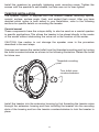
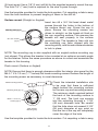
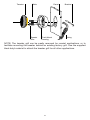
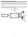
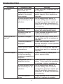
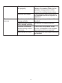
Component Speakers
355cs
356cs
table of contents
introduction . . . . . . . . . . . . . . . . . . . . . . . . . . . . . . . . . . . . . . . . . . . . . . . . . . . . . 3
about this manual . . . . . . . . . . . . . . . . . . . . . . . . . . . . . . . . . . . . . . . . . . . . . . . . 3
features . . . . . . . . . . . . . . . . . . . . . . . . . . . . . . . . . . . . . . . . . . . . . . . . . . . . . . . . 3
cautions . . . . . . . . . . . . . . . . . . . . . . . . . . . . . . . . . . . . . . . . . . . . . . . . . . . . . . . . 5
installation planning . . . . . . . . . . . . . . . . . . . . . . . . . . . . . . . . . . . . . . . . . . . . . . . 6
amplifier requirements . . . . . . . . . . . . . . . . . . . . . . . . . . . . . . . . . . . . . . . . . . . . . 6
mounting locations . . . . . . . . . . . . . . . . . . . . . . . . . . . . . . . . . . . . . . . . . . . . . . . 6
specifications . . . . . . . . . . . . . . . . . . . . . . . . . . . . . . . . . . . . . . . . . . . . . . . . . . . . 7
crossover features and connections . . . . . . . . . . . . . . . . . . . . . . . . . . . . . . . . . . 9
speaker wiring . . . . . . . . . . . . . . . . . . . . . . . . . . . . . . . . . . . . . . . . . . . . . . . . . . 10
speaker installation . . . . . . . . . . . . . . . . . . . . . . . . . . . . . . . . . . . . . . . . . . . . . . 11
tweeter installation . . . . . . . . . . . . . . . . . . . . . . . . . . . . . . . . . . . . . . . . . . . . . . . 12
crossover installation . . . . . . . . . . . . . . . . . . . . . . . . . . . . . . . . . . . . . . . . . . . . . 17
connecting the system . . . . . . . . . . . . . . . . . . . . . . . . . . . . . . . . . . . . . . . . . . . . 18
crossover connections and input switch setting . . . . . . . . . . . . . . . . . . . . . . . . 19
bi-amplified connections to crossover . . . . . . . . . . . . . . . . . . . . . . . . . . . . . . . . 20
bi-wire connections to crossover . . . . . . . . . . . . . . . . . . . . . . . . . . . . . . . . . . . . 21
troubleshooting . . . . . . . . . . . . . . . . . . . . . . . . . . . . . . . . . . . . . . . . . . . . . . . . . 22
notes . . . . . . . . . . . . . . . . . . . . . . . . . . . . . . . . . . . . . . . . . . . . . . . . . . . . . . . . . 25
introduction
Thank you for choosing PrecisionPower™ automotive component loudspeakers.
These reference quality speakers combine the acoustic excellence achieved from
25 years of loudspeaker research and development, with innovative and timeless
industrial design, and cutting edge material choices. Tuned for precise reproduction
of the supplied musical signal, they accurately deliver every nuance and detail
while retaining the classic "PrecisionPower™ sound" that has enchanted multiple
generations of owners. With a minimum of care, this high performance component
speaker system will deliver years of trouble-free satisfaction.
about this manual
To achieve optimum performance from your PrecisionPower™automotive
component loudspeakers, we recommend that you read this manual thoroughly
before installation and use. For the best results and support, please consult
with your local authorized PrecisionPower™ retailer. Technical support is also
available from PrecisionPower™ at 1-800-753-0800 selection 3. Keep this
manual in a safe place for future reference.
features
Molded woofer basket - The backbone of any good woofer is its basket. It provides
the proper alignment and support structure for the magnet and moving parts while
the very thin braces guarantee a minimum of early reflections off the basket that
would be ordinarily transmitted as sonic colorations through the cone.
Woofer cone - Interlaced Aramid Fiber (Kevlar) with Mica and fiberglass mixture
in a IMPP (Injection Molded Poly Propylene) base, cones provide the perfect
combination of rigidity and low moving mass for ultra-low distortion and superior
transient response.
Vented voice coil - Magnet cooling vent construction enhances power handling
capabilities of the woofer. The voice coil is made using copper clad aluminum wire
to minimize weight and increase efficiency and low frequency response.
Extended center pole - Woofer magnet geometry provides a symmetrical magnetic
pattern to reduce THD.
Tweeter - Ultra-light silk dome design is treated with polymer compound to control all
non-linear resonances.
Multi-mount tweeter - The following mounting options (surface, angled surface,
flush, or angled flush) are supplied to mount the ferrofluid cooled neodymium
tweeter.
Tweeter level control - A three-position switch adjusts the volume of the tweeter
with respect to the midrange.
Tweeter phase switch - A two-position switch which allows 180° or 0° phase
difference between the tweeters and midranges.
Midrange contour control - A two-position switch offers a frequency response
correction circuit to adjust for flat frequency response in the car on axis or off
axis.
Bi-amplifiable/ bi-wirable - The passive crossover supplied with this system is biamplifiable or bi-wirable; typically only available in high quality audiophile home
loudspeakers.
Solid state tweeter protection - Advanced protection circuitry provides protection
for the tweeter against overpowering or amplifier clipping.
Cautions
Study your automobile thoroughly before you drill or cut any holes. Take extra care
when working near gas tanks, gas lines, brake or hydraulic lines and electrical
wiring.
Wear eye and ear protection when using power tools. Keep the woofers and
tweeters away from metal filings and shavings. Once foreign objects are stuck to
the magnets or tweeter dome, it will be virtually impossible to remove them. Keep
the tweeters in their protective bags until final mounting to prevent any possibility
of metal dust or chips from passing through the grille and accumulating on the
dome.
Exercise caution when working with the cs series with the grille removed. A slip of
the hand with a screwdriver or other tool can result in irreparable damage to the
cone or dome. Do not touch the cone or dome.
Do not install the components where they will be subject to excessive heat,
moisture or dust, or where they will be kicked or repeatedly bumped or brushed.
Make absolutely sure that the woofer is connected to the lowpass output and the
tweeter is connected to the highpass output of the crossover network. If these
connections are reversed, low-frequency signals will be fed to the tweeter without
fuse protection. In this case, the tweeter may be damaged, such damage is not
covered by the warranty.
When removing or installing the grills be careful not to brush the woofer's rubber
surround or the tweeter's dome with the edge of the grille. Cutting or tearing the
surround or dome will destroy the unit.
Never run wires outside or beneath the vehicle where they can be snagged by
road hazards or the moving parts of the vehicle. Use existing wire channels,
sills, panels and molding strips inside the automobile to hide the wiring for neat
appearance and safety.
Make sure your radio/cassette/cd player and or other equipment is turned off
while connecting the speaker terminals. Turn on the various components and
slowly advance the volume control ONLY after checking and double checking all
connections.
NOTE: If the sound is weak or distorted, immediately turn down the volume and
see the section entitled Troubleshooting.
installation planning
Proper installation planning is the best way to maximize performance. By planning
your installation carefully you can avoid situations where the performance or
reliability of your system is compromised. Your authorized PrecisionPower™
dealer or PrecisionPower™ audio technical support at 1-800-753-0800 selection
3 has been trained to know how to maximize your speakers sonic potential. They
are a valuable resource in helping you with your system design and installation.
amplifier requirements
This speaker system requires a minimum of 45 watts per channel to achieve
reasonable listening volumes in a moving automobile without clipping the amplifier.
PrecisionPower™ recommends no more than 150 watts per channel as a
maximum so as not to exceed the thermal or mechanical limitations of the speaker
system. Any amplifier between 45 watts and 150 watts may be used. If you choose
to use an amplifier with more than 150 watts use caution as speaker damage may
occur at high volume settings. All PrecisionPower™ loudspeakers will produce
reasonable volume levels in the automotive environment using moderate amplifier
power. However, the use of a low powered amplifier to try and attain very high
volume levels can lead to overdriving the amplifier and damaging the speaker
system. As a rule, do not turn the volume up above the point where you hear
distortion on musical peaks from either an overdriven amplifier or mechanical
noise from an overstressed speaker. For the best performance and reliability;
select an amplifier with slightly more than the maximum power you are likely to
need to generate the desired volume levels. This margin of reserve power will
ensure that the amplifier will not be routinely driven beyond its design limits.
Warning: Excessive sound pressure level can permanently damage your
hearing. The maximum volume levels attainable with PrecisionPower™ speakers,
combined with high-power amplification, may exceed safe levels of extended
listening.
mounting locations
There are many possible choices of mounting locations. The vehicle factory
locations will usually dictate the woofer mounting position. Because of its small
size and multiple mounting options, the tweeter can go virtually anywhere.
PrecisionPower™ uses an unusually low crossover frequency for the tweeter
which means you are not restricted to mounting the tweeter close to the midrange
speaker. The tweeter can be mounted as far as 24" (60 cm) from the midrange
speaker without causing adverse effects on the sound quality. However, better
results are usually obtained by locating the tweeters and midranges relatively
close to each other, and by keeping the sound path lengths between the listener
and the left and right speakers as equal as possible.
PrecisionPower™ cannot recommend specific tweeter mounting locations for
each vehicle, but in general try to keep the tweeters as far to the sides of the car
as practical. Avoid placing them above ear level unless the woofers are also above
ear level. Place the tweeters in similar locations on both sides of the vehicle. Try
a few locations by just placing the tweeter or taping it in a location and listening
to ensure the desired stereo image and high frequency dispersion are achieved
before committing to a location by drilling holes in the vehicle. You should also
experiment with the tweeter phase switch settings to find the most effective
combination of location and phase.
Specifications
355cs
356cs
Frequency response
77Hz -22kHz
60Hz -22kHz
Sensitivity
86db
87db
Impedance
4 ohms
4 ohms
Recommended amplifier
power
50/100
60/120
Mounting depth (woofer)
(in)
2.5
2.5
Fs
77.28 Hz
65.96 Hz
Re
3.40 ohms
3.40 ohms
Qms
6.24
5.91
Qes
0.64
0.65
Qts
0.58
0.58
L1
.52
.5
Vas (L)
3.57
7.38
Mms (Kg)
.012
.013
Cms
.298
.437
BI
6.22
5.38
Xmax
.11328
.11328
Crossover features and connections
Tweeter
DC Clip
Protection
Tweeter
Thermal
Breaker
Midrange
Contour Switch
Tweeter
Phase Switch
Parallel Bi-amp
Switch
Tweeter Level
Switch
IN
OUT
Woofer Tweeter Woofer Tweeter
+ + + + demo
car
180°
p
b
0
-3
0°
+3
Midrange Contour switch
Positions of Demo or Car are provided to offer different contours to midrange
woofer frequency response. This switch should be left in the Car position for most
applications.
Bi-amp/Parallel switch
Select the Bi-amp position if you intend on driving the woofers and tweeters with
separate amplifiers (four channels). Select the Parallel position if you intend on
driving the woofers and tweeters with the same amplifier (two channels).
Tweeter Level switch
The three-position switch in the crossover box adjusts the output level of the
tweeter. The mid-position (0) is referenced as equal output from the midrange
speaker and the tweeter. The high position (+3) provides 3dB more output from
the tweeter. The low position (-3) provides 3dB less output from the tweeter. Select
the position of this switch for your listening preference.
Tweeter Phase switch
Select 0 or 180 degrees phase relationship between the tweeters. Select the
position of this switch for your listening preference.
Tweeter Thermal breaker
This component protects the tweeter speaker if too much power is delivered to the
tweeter. If activated the tweeter will briefly stop producing sound until the breaker
automatically resets.
Tweeter DC Clip Protector
These components limit the amount of current delivered to the tweeter if they are
overdriven by either excess amplification or clipped signal from an overdriven
amplifier.
Connections to the amplifier
The crossovers are supplied with a removable screw type connector. The
crossover has two sets of input terminals, this allows the system to be driven by
either two or four channels of amplification. To correctly use these wiring schemes
you must move the Bi-amp/Parallel switch to the desired position.
To bi-amplify the system you will need two stereo amplifiers (or 4 amplifier
channels) with one pair of channels to drive the tweeters and one pair to drive
the woofers.
You may also Bi-wire the system by connecting the woofer input terminals to the
amplifier and connecting the woofer input terminals to the same amplifier with
another set of speaker wires. This is sometimes done to allow a specific high
frequency or low frequency cabling to be used for the two separate signal paths.
See Crossover Installation for additional information on bi-wiring.
Be sure to connect the positive crossover terminals to the positive speaker
terminals and positive amplifier terminals, also ensure that the negative crossover
terminals connect to the negative amplifier and speaker terminals. Once all of the
wires are attached to the connector and the crossover is mounted, the connector
can be plugged into its mating receptacle on the crossover.
SPEAKER WIRING
Speaker wire selection
Use insulated two-conductor stranded wire to connect the crossover to the
speakers and amplifier. The size of the wire can have an audible effect of the
performance of the system. Stranded 18 gauge "zip cord" will work, but can result
in lower output or unpredictable frequency response. For wire runs of 50 feet (15
m) or less, we recommend 16 gauge or larger wire. The crossover connector will
accept up to 14 gauge wire.
Polarity and phasing
The polarity of the positive/negative orientation of the connections for every
speaker and amplifier connection must be consistent so all the speakers will be
in phase. When the polarity of one connection is reversed, bass output may be
reduced or stereo imaging degraded. Most speaker wire is marked so you can
identify the two conductors. There may be ribs or a stripe on the insulation of one
conductor, or the wire may have clear insulation with different color conductors
(copper and silver). There may also be polarity indications printed on the
insulation. Identify the positive and negative conductors and be consistent with
10
every speaker and amplifier connection. The supplied speaker wire has a white
stripe to indicate the (+) positive conductor.
Termination
The woofer uses an angled locking screw connection integrated to the basket of
the speaker. The tweeter wires are terminated with molded connectors (male and
female). Use the supplied wire with insulated connectors to extend the tweeter
wires to the crossover section. Alternatively you may solder the tweeter wire
connections and insulate them with high quality heat shrink tubing.
SPEAKER INSTALLATION
Woofer installation
The woofer will fit into many standard factory mounting locations using the
existing mounting holes in the automobile. Remove the trim panels and inspect
the installation locations before you cut and drill the holes required to mount the
woofer. Removing the panel will also make it much easier to route wiring inside
the door. Look for original equipment speaker installation cutouts that can be used
to install the woofers with little or no modifications. Use the supplied template to
help you locate and mark the holes needed to install the speakers.
If the planned installation location is in a door panel, be sure the speaker will not
interfere with the window lowering mechanism. Ensure that the speaker wires are
positioned to clear all moving parts inside the door.
For each woofer you will need to cut one large hole and drill small holes around
the circumference. If the mounting surface is covered by carpet or fabric, use a
knife or razor to cut the material away from the holes to be cut. This prevents
material or fibers from becoming tangled in the drill bit or cutting blade. If you
are using the packaged metal screws provided in the hardware kit, drill the four
speaker mounting screw holes with a 1/8"(3 mm) drill.
Clean the work areas of all filings and shavings with a vacuum cleaner before you
proceed with woofer mounting.
Woofer mounting
Route the speaker wire from the woofer installation locations to the crossovers.
Pull the wire through the installation hole and attach the terminals on the ends
to terminals connections on the speakers. Refer to the speaker wiring section of
this manual and the wiring diagrams. Push the wire back into the area behind
the installation location and be sure it will not interfere with the speaker or get
snagged by any mechanisms in the area.
Attach the supplied foam gasket strip to the mounting surface of the speaker.
This will ensure an air tight seal, which is required to achieve the best bass
performance.
11
Install the speakers by gradually tightening each mounting screw. Tighten the
screws until the speaker is well seated, but take care not to over-tighten.
TWEETER INSTALLATION
The speaker system is supplied with five different tweeter mounting options:
coaxial, surface, surface angle, flush, and angled flush mount. After you have
decided which option is best suited to your installation, refer to the following
sections for specific details on mounting the tweeter.
Coaxial mount
These components have the unique ability to also be used as a coaxial speaker
in specific applications. This allows the tweeter to be placed directly in the center
of the woofer without obstructing the voice coil or the function of the woofer.
CAUTION: Use caution to not damage the speaker cone in the procedure
described in the next steps.
Unscrew and remove the center bullet from the threaded mounting post by turning
the bullet counterclockwise as shown in the following illustration. Retain the bullet
for future use.
Threaded mounting
post
Turn bullet nose
counterclockwise
Install the tweeter into the extension housing by first threading the tweeter wires
through the extension housing and then installing the tweeter into the mounting
slots of the housing and turn the tweeter counterclockwise to lock the tweeter in
place.
12
Coaxial
Extension
Tweeter
Tweeter
Speaker
Wires
Mounting
Slots (qty 4)
Mounting
Tabs (qty 4)
CAUTION: Do NOT overtighten the tweeter assembly.
Now feed the tweeter speaker wires through the front center of the woofer (where
the aluminum bullet was removed) As shown in the next illustration. Align and
thread the coaxial tweeter assembly on the threaded post in the center of the
woofer. Rotate the coaxial tweeter assembly clockwise until snug. Connect the
tweeter wires to the tweeter output from the crossover.
Threaded mounting
post
Turn tweeter
coaxial mount
assembly
clockwise
The tweeter is mounted at and angled relative to the woofer. Before final woofer
mounting, rotate the woofer so that the tweeter is pointed in the desired direction,
typically towards the listener's ear location.
Surface mount (Straight or Angled)
The preparation of the mounting surface for the tweeter involves drilling three
holes. Two holes are for the mounting screws. Their centers must be spaced15/16”
13
(24 mm) apart. Use a 1/8" (3 mm) drill bit for the supplied screws to mount the cup.
The third 1/4” (7 mm) hole is required for the wire to pass through.
Use the template provided to locate the hole centers. Cut carpeting or fabric away
from the hole locations to prevent tangling of fibers in the drill bit.
Surface mount (Straight or Angled)
Insert two #6 x 3/4" flat head sheet metal
screws through the holes in the bottom of
the surface mount cup. Screw the cup in
place. Ensure the mounting screws are
driven in straight, so the heads sit flush on
the cup mounting surface. This ensures the
tweeter will seat properly in the surface
mounting cup. The tweeter is then slid into
the mounting cup (tabs aligned with the
mounting slots), and turned counterclockwise
to lock in place.
Mounting slots (qty 4)
#6 x 3/4" screws
(qty 2)
NOTE: The mounting cup is also supplied with an angled surface mounting cup
(not shown). This allows the tweeter to be mounted at an optimum acoustic angle
for the listener. Follow the same procedure as above to mount and assemble the
tweeter in this housing.
Flush mount (Surface or Angled)
Note: Ensure that there is enough clearance within the interior door panel for the
M4-0.7 X 4-1/2 cm (1.77 inches) flat head mounting screws. Reduce the length of
the mounting screw as necessary to meet clearance.
Check the intended installation site
to be sure that there is sufficient
depth behind the mounting surface
for the rear cup and mounting screws.
The minimum depth required behind
the back of the mounting surface is
1" (25 mm). The front cup mounts
into the mounting through a 1-7/8"
(48 mm) diameter hole. Be careful
that the hole does not exceed 2-1/8"
(55 mm) diameter at any point so
that the rim of the cup will completely
cover the edge of the hole.
Metal mounting bracket
Mounting slots (qty 4)
M4-0.7 x 4-1/2 cm
screws (qty 2)
Flush Angled
Mounting Cup
Use the template provided to locate the hole centers. Cut carpeting or fabric away
14
from the hole locations to prevent tangling of fibers in the saw blade.
Insert the two M4-0.7 X 4-1/2 cm (1.77 inches) flat head metal screws through the
mounting holes and just start the threads into the metal mounting bracket. With
the metal bracket attached to the mounting cup slide one end of the metal bracket
and then the other end into the mounting hole. Hold the mounting cup in its final
position and tighten, but do not over tighten the two mounting screws.
The tweeter is then slid into the mounting cup (tabs aligned with the mounting
slots), and turned counterclockwise to lock in place.
NOTE: The mounting cup is also supplied with an angled surface mounting cup
(not shown). This allows the tweeter to be mounted at an optimum acoustic angle
for the listener. Follow the same procedure as above to mount and assemble the
tweeter in this housing.
Tweeter mounting
Route the wire from the crossover locations to the tweeter locations. Pull the wire
through the wire hole and attach crossover wires to the wires from the tweeters.
Connect the positive wire to the positive (+) terminal of the tweeter, which is
marked with the white trace. See the information in the speaker wiring section
of this manual and the wiring diagrams. Push the wire back into the area behind
the installation location and be sure it will not interfere with the speaker or with
anything behind the mounting panel. To attach the tweeter to the surface or flush
mount assembly, align the tabs in the mounting cup with the relieved areas in the
tweeter mount.
Mounting
Screws
Tweeter
TWEETER
Tweeter
Wiring
Surface Mount Housing
Panel
15
Wiring
Tweeter
Bolts
Tweeter
Wire
Panel
Flush Mount
Housing
Bracket
Wiring
NOTE: The tweeter grill can be easily removed for coaxial applications, or to
facilitate mounting the tweeter behind an existing factory grill. Use the supplied
black butyl material to attach the tweeter grill for all other applications.
16
Crossover INSTALLATION
The system supports conventional wiring, Bi-wiring or Bi-amping using the
supplied passive crossovers. While conventional (parallel mode) wiring will provide
excellent sound, bi-wiring or bi-amping may further enhance the performance in
no-compromise systems.
Bi-wiring uses a separate pair of speaker wires for the high frequency and low
frequency signal between an amplifier channel and its associated crossover
network. This gives you the option of choosing wire which may have slightly
different sonic characteristics in order to optimize performance of each frequency
range. Also, it reduces the overall wiring resistance between the crossover and
amplifier, much like the use of larger gauge wire. This option provides the most
benefit when the crossover network is mounted a long distance away from the
amplifier. If the crossover is mounted close to the amplifier it is doubtful that there
will be an appreciable difference between bi-wiring and conventional wiring.
Bi-amping uses a separate amplifier channel for the high-frequency and lowfrequency sections, instead of the single amplifier channel used in conventional
and bi-wired connections. Bi-amping provides the additional advantage of allowing
use of the amplifier's level controls to provide an additional level of fine-tuning not
possible with the tweeter-level switch alone. In addition, at high power levels, a
bi-amplified connection can help protect the tweeter from amplifier clipping, which
is more likely to occur on channels driving the midrange. When bi-amping using
the passive crossovers, the midrange low-pass filter and tweeter high-pass filter
on the amplifier or external active crossover should be bypassed.
Carefully route the wires from the woofer and tweeter to the crossover mounting
location. The crossover installation location should be reasonably accessible to
allow easy connection of the wires and adjustment of the internal switches. If the
crossover must be mounted in an inaccessible location make the speaker wire
connections and adjustments before final installation. Be sure the installation
location has adequate clearance to allow the removal and replacement of the
cover. Mounting the crossover requires removing the top cover of its housing.
Grasp the top cover at the front and back. Compress the cover slightly in the
center and lift it off the bottom of the housing. Mounting the crossover requires
four holes in a rectangular pattern 2 13/16" x 4 1/4" (7.14 cm x 10.8 cm) on a flat
surface. Use the crossover as a template for drilling the mounting holes.
Align the mounting holes in the bottom half of the crossover unit with the holes
you have drilled at the installation site. Pass the four #6 x 1 1/4" screws through
the holes in the crossover unit, and tighten them until the assembly is firmly in
place. As before, do not over-tighten; this is especially important if the mounting
surface is not perfectly flat.
17
After all the connections and any necessary adjustments have been made snap
the cover back in place.
connecting the system
Trim the speaker wire as needed. Strip about 1/4" (6 mm) of the insulation from
the ends. Twist the exposed strands thoroughly to prevent any loose strands from
causing a short circuit. You may also "tin" the wire with a soldering iron. The wires
attach to a removable connector which in its assembled position has the screws
facing the bottom of the crossover. Insert the prepared wire into the appropriate
location (see diagram or refer to the crossover circuit board) in the connector strip
and tighten the screws to secure the wires in place. Be sure to note the polarity
marking on the circuit board.
18
Crossover CONNECTIONS AND INPUT SWITCH SETTING
Route the wires connected to the input terminals on the crossover network to the
power amplifier. Connect the wires to the amplifier outputs as recommended by
the manufacturer of the unit. Make sure there are no stray strands of wire which
could cause a short circuit. Observe left/right polarity markings.
6WDQGDUG
6ZLWFKLQ3DUDOOHO3RVLWLRQ
7ZHHWHU
%LDPS3DUDOOHO
,1
Amplifier
287
7ZHHWHU
&URVVRYHU
:RRIHU
7ZHHWHU
:RRIHU
:RRIHU
NOTE: In this configuration, you may connect the amplifier (+) positive to either
the tweeter (+) or woofer (+) terminal, and the amplifier (-) negative to either the
tweeter (-) or woofer (-) terminal. The parallel switch ensures that both halves of
the crossover are supplied with signal as least one (+) and (-) input terminal are
connected.
19
BI-AMPLIFIER CONNECTIONS TO CROSSOVER
Connections from the crossover to the woofer and tweeter are the same as the
normal wiring method. Connect the amplifier you have chosen for the tweeter to
the “Tweeter In” terminals input. Connect the woofer amplifier to the “Woofer In”
terminals.
NOTE: You must move the selectable switch to the Bi-amp position. Failure to set
the switch correctly may cause damage to the amplifiers or the crossover.
Bi-Amplified
(Switch in Bi-amp Position)
Tweeter
P
+
IN
Tweeter Amplifer
-
B
+
-
+
-
OUT
+
Tweeter
-
Tweeter
Woofer
Crossover
+
+
-
+
Woofer
-
Woofer
Woofer Amplifer
-
20
-
+
BI-WIRE CONNECTIONS TO CROSSOVER
Connections from the crossover to the woofer and tweeter are the same as the
normal wiring method. Connect the amplifier to the tweeter input terminals with
one run of wire. Connect the amplifier to the woofer input terminals with another
run of wire.
NOTE: You must move the Bi-amp/parallel switch to the parallel position. Failure
to set the switch correctly will not damage the equipment, but could interfere with
any enhancement of the sound due to bi-wiring.
Bi-Wired
(Switch in Parallel Position)
Tweeter
P
B
IN
+
+
-
-
+
+
-
OUT
+
Tweeter
-
Tweeter
Woofer
Crossover
Amplifer
-
+
Woofer
-
Woofer
21
-
+
tROUBLESHOOTING
Symptom
No output
Probable Cause
Remedy
Source or amplifier
not turned on.
Check source or amplifier and fix
as required.
Audio input not connected or no output
from source.
Check RCA connection and
signal integrity, fix or replace as
required.
Bi-amp/parallel switch Set Bi-amp/parallel switch to
set incorrectly for ap- correct setting (see Crossover
plication.
connections and input switch setting, Bi-amplified connections to
crossover, or Bi-wire connections
to crossover).
Audio cycles on
and off
Distorted output
Protection circuit
activated.
Turn down volume, protection
circuit will automatically reset.
Speaker wires not
connected.
Check speaker wires and fix or
replace as required.
Speaker damaged.
Check system with known working speaker and fix or replace as
required
Thermal protection
engaged.
Check that amplifier has adequate ventilation, check speaker
impedance load
Loose or poor audio
connections.
Check RCA power and speaker
connections and fix or replace as
required.
Preamp volume set
Check volume or preamp and
to high exceeding
adjust appropriately.
maximum capability of
amplifier.
Impedance load to
amplifier too low.
Check speaker impedance load, if
below 1 ohm rewire the speakers
to achieve a higher impedance.
Bi-amp/parallel switch Set Bi-amp/parallel switch to
set incorrectly for ap- correct setting (see Crossover
plication.
connections and input switch setting, Bi-amplified connections to
crossover, or Bi-wire connections
to crossover).
Shorted speaker
wires.
Check speaker wire connections
and fix or replace as needed.
22
Poor bass response
Speaker not connected properly.
Check speaker wring and fix or
replace as needed. Refer to the
speaker wiring section of this
manual for detailed instructions.
Speaker damaged.
Check system with known working speaker and fix or replace as
required
Speakers wired with
wrong polarity.
Check speaker polarity and fix as
needed.
Stereo/bridge switch
set to bridge position.
Set switch to stereo position.
Speaker connected
across wrong output
terminals.
Check that the speaker wires
are not connected to the bridged
terminals and fix as needed
Source set to mono.
Check source and adjust controls
as needed
23
24
Notes
________________________________________________________________
________________________________________________________________
________________________________________________________________
________________________________________________________________
________________________________________________________________
________________________________________________________________
________________________________________________________________
________________________________________________________________
________________________________________________________________
________________________________________________________________
________________________________________________________________
________________________________________________________________
________________________________________________________________
________________________________________________________________
________________________________________________________________
________________________________________________________________
________________________________________________________________
________________________________________________________________
________________________________________________________________
________________________________________________________________
________________________________________________________________
________________________________________________________________
________________________________________________________________
________________________________________________________________
________________________________________________________________
________________________________________________________________
________________________________________________________________
________________________________________________________________
________________________________________________________________
________________________________________________________________
________________________________________________________________
________________________________________________________________
________________________________________________________________
________________________________________________________________
________________________________________________________________
________________________________________________________________
________________________________________________________________
________________________________________________________________
________________________________________________________________
________________________________________________________________
________________________________________________________________
________________________________________________________________
________________________________________________________________
25
Warranty
LIMITED ONE-YEAR CONSUMER WARRANTY/
*LIMITED TWO-YEAR CONSUMER WARRANTY FOR AUTHORIZED DIRECTED DEALER
PURCHASE & INSTALLATION
Directed Electronics (herein “Directed”) promises to the original purchaser, to repair or replace with a
new or refurbished unit (at Directed’s sole and absolute discretion) this product should it prove to be
defective in workmanship or material under normal use, for a period of *two-years from the date of
purchase from the authorized Directed dealer PROVIDED the product was purchased and installed by
an authorized Directed dealer. During this *two-year period, there will be no charge for the repair or
replacement PROVIDED the unit is returned to Directed, shipping prepaid, along with the required proof
of installation, the bill of sale or other dated proof of purchase, and the consumer’s contact information.
If the unit is installed by anyone other than an authorized Directed dealer, the warranty period will be
one-year from the date of purchase. This warranty is non-transferable and does not apply to any unit
that has been modified or used in a manner contrary to its intended purpose, and does not cover damage
to the unit caused by installation or removal of the unit. During this one-year period, there will be no
charge for the repair or replacement PROVIDED the unit is returned to Directed, shipping pre-paid,
along with the bill of sale or other dated proof of purchase and the consumer’s contact information. This
warranty is void if the product has been damaged by accident or unreasonable use, neglect, improper
service or other causes not arising out of defects in materials or construction. This warranty does not
cover the elimination of externally generated static or noise, or the correction of antenna problems or
weak reception, damage to speakers, accessories, electrical systems, cosmetic damage or damage due
to negligence, misuse, failure to follow operating instructions, accidental spills or customer applied
cleaners, damage due to environmental causes such as floods, airborne fallout, chemicals, salt, hail,
lightning or extreme temperatures, damage due to accidents, road hazards, fire, theft, loss or vandalism,
damage due to improper connection to equipment of another manufacturer, modification of existing
equipment, or Product which has been opened or tampered for any reason. Units which are found to
be damaged by abuse resulting in thermally damaged voice coils are not covered by this warranty but
may be replaced at the absolute and sole discretion of Directed. Unit must be returned to Directed,
postage pre-paid, with bill of sale or other dated proof of purchase bearing the following information:
consumer's name, telephone number, and address, authorized dealer's name and address, and product
description. Unit must be returned to the following address: ATTN: WARRANTY DEPARTMENT, Directed
Electronics , 1 Viper Way, Vista, CA 92081. Note: This warranty does not cover labor costs for the removal
and reinstallation of the unit. IN ORDER FOR THE TWO-YEAR WARRANTY TO BE VALID, YOUR UNIT
MUST BE SHIPPED WITH PROOF OF INSTALLATION BY AN AUTHORIZED DIRECTED DEALER. ALL UNITS
RECEIVED BY DIRECTED FOR WARRANTY REPAIR WITHOUT PROOF OF DIRECTED DEALER INSTALLATION
AND PURCHASE WILL BE COVERED BY THE LIMITED 1 YEAR WARRANTY.
BY PURCHASING THIS PRODUCT, ALL WARRANTIES INCLUDING BUT NOT LIMITED TO EXPRESS
WARRANTY, IMPLIED WARRANTY, WARRANTY OF MERCHANTABILITY, FITNESS FOR PARTICULAR
PURPOSE, AND WARRANTY OF NON-INFRINGEMENT OF INTELLECTUAL PROPERTY ARE EXPRESSLY
EXCLUDED TO THE MAXIMUM EXTENT ALLOWED BY LAW, AND DIRECTED NEITHER ASSUMES NOR
AUTHORIZES ANY PERSON TO ASSUME FOR IT ANY LIABILITY IN CONNECTION WITH THE SALE OF
THE PRODUCT. DIRECTED HAS ABSOLUTELY NO LIABILITY FOR ANY AND ALL ACTS OF THIRD PARTIES
INCLUDING ITS AUTHORIZED DEALERS OR INSTALLERS. IN NO EVENT WILL DIRECTED BE LIABLE FOR ANY
INCIDENTAL, SPECIAL OR CONSEQUENTIAL DAMAGES (INCLUDING LOSS OF PROFITS). BY PURCHASING
THIS PRODUCT, THE CONSUMER AGREES AND CONSENTS THAT ALL DISPUTES BETWEEN THE CONSUMER
AND DIRECTED SHALL BE RESOLVED IN ACCORDANCE WITH CALIFORNIA LAWS IN SAN DIEGO COUNTY,
CALIFORNIA. This warranty is only valid for sale of Product within the United States of America. Product
sold outside of the United States of America is sold “AS-IS,” and shall have NO WARRANTY, express or
implied. Some states do not allow limitation on how long an implied warranty lasts. In such states, the
limitation or exclusions of this Limited Warranty may not apply. Some states do not allow the exclusion
or limitation of incidental or consequential damages. In such states, the exclusion or limitation of this
Limited Warrantymay not apply to you. This Limited Warranty gives you specific legal rights, and you may
have other rights which vary from state to state. 920-0033 Rev 02-07
To find out more about other Precision Power products please visit: www.precisionpower.com
© 2007 Directed Electronics. All rights reserved. G39302.07 2007-09