1
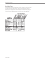
Modula Documentation
q
q
q
q
q
q
ESD Warning
Safety Information & Notices
Welcome
Installation and Setup Guide
Warranty/Service & Returns
Glossary
Control Options
q
q
q
q
CP-20A Control Panel Operation (Front)
CP-10 Control Panel Operation (Front & Remote)
CP-20 Control Panel Operation (Front & Remote)
Serial Control Operation (BCS)
Enclosure (Board Set) Supplements*
q
q
q
q
q
q
q
q
Standard Video Enclosures
S-Video & Stereo Enclosures
CAT-5 Video & Audio Enclosures
CAT-5/RGBHV Enclosure
Wideband Enclosures
Stereo (with Wideband) Enclosures
SDI Digital Video Enclosures
Series4 (CatPro and RGBHV/HD-15) Enclosures
Mounting Accessories
q
q
q
Transmitter/Receiver Module Mounting Plate
Module Rack Mounting Tray
12-Box Rack Mount 4 RU Enclosure
Miscellaneous Supplements
q
CAT-5 Wiring Diagrams for Transmitter/Receiver Link Cable
* To search the Enclosure Supplements according to board signal type, see the
chart on the next page.
August 2006
Modula Documentation
Board Signal Types
Each Enclosure (Board Set) Supplement includes a chapter for each board signal
type that can be used in that enclosure. The dots in the chart below indicate
which Enclosure Supplements contain information for the different signal types.
Click the Enclosure Supplement name on the left to go to that supplement.
August 2006
ESD Warning
To avoid ESD (Electrostatic Discharge) damage to sensitive components,
make sure you are properly grounded before touching any internal
materials.
When working with any equipment manufactured with electronic
devices, proper ESD grounding procedures must be followed to ensure
people, products, and tools are as free of static charges as possible.
Grounding straps, conductive smocks, and conductive work mats are
specifically designed for this purpose.
Anyone performing field maintenance on AutoPatch equipment should
use an appropriate ESD field service kit complete with at least a
dissipative work mat with a ground cord and a UL listed adjustable wrist
strap with another ground cord. These items should not be manufactured
locally, since they are generally composed of highly resistive conductive
materials to safely drain static charges, without increasing an
electrocution risk in the event of an accident. ESD protective equipment
can be obtained from 3M™, Desco®, Richmond Technology®, Plastic
Systems®, and other such vendors.
Modula Binder Introduction
When using and installing your AutoPatch product, adhere to the following basic safety
precautions. For more information about operating, installing, or servicing your
AutoPatch product see your product documentation.
ä Read and understand all instructions before using and installing AutoPatch products.
ä Use the correct voltage range for your AutoPatch product.
ä There are no user serviceable parts inside an AutoPatch product; service should only
be done by qualified personnel.
ä If you see smoke or smell a strange odor coming from your AutoPatch product, turn
it off immediately and call AutoAssist.
ä Turn off and unplug an enclosure before adding or removing boards, unless otherwise
specified in that product’s documentation.
ä To avoid shock or potential ESD (Electrostatic Discharge) damage to equipment,
make sure you are properly grounded before touching components inside an
AutoPatch product.
ä For products with multiple power supplies in each unit, make sure all power supplies
are turned on simultaneously.
ä Use surge protectors and/or AC line conditioners when powering AutoPatch
products.
ä Only use a fuse(s) with the correct fuse rating in your enclosure.
ä Make sure the power outlet is close to the product and easily accessible.
ä Make sure the product is on or attached to a stable surface.
ä Turn off equipment before linking pieces together, unless otherwise specified in that
product’s documentation.
ä For safety and signal integrity, use a grounded external power source and a grounded
power connector.
Modula Binder Introduction
Safety
Important Safety Information
and Instructions
Safety
Information et directives
de sécurité importantes
Veuillez vous conformer aux directives de sécurité ci-dessous lorsque vous installez et
utilisez votre appareil AutoPatch. Pour de plus amples renseignements au sujet de
l’installation, du fonctionnement ou de la réparation de votre appareil AutoPatch, veuillez
consulter la documentation accompagnant l’appareil.
ä Lisez attentivement toutes les directives avant d’installer et d’utiliser les appareils
AutoPatch.
ä Le voltage doit être approprié à l’appareil AutoPatch.
ä Les appareils AutoPatch ne contiennent aucune pièce réparable par l’usager; la
réparation ne doit être effectuée que par du personnel qualifié.
ä Si de la fumée ou une odeur étrange se dégagent d’un appareil AutoPatch, fermez-le
immédiatement et appelez le Service de soutien technique (AutoAssist).
ä Fermez et débranchez le boîtier avant d’ajouter ou d’enlever des plaquettes, à moins
d’indication contraire fournie dans la documentation du appareil.
ä Pour éviter les chocs ou les dommages éventuels causés à l’équipement par une
décharge électrostatique, veillez à ce le dispositif oit bien relié à la terre avant de
toucher les composantes se trouvant à l’intérieur d’un appareil AutoPatch.
ä Veillez à ce que tous les blocs d’alimentation des appareils dotés de blocs
d’alimentation multiples dans chaque unité soient allumés simultanément.
ä Servez-vous de protecteurs de surtension ou de conditionneurs de lignes à courant
alternatif lorsque vous mettez les appareils AutoPatch sous tension.
ä Placez uniquement des fusibles de calibre exact dans les boîtiers.
ä Veillez à ce que la prise de courant soit proche de l’appareil et facile d’accès.
ä Veillez à ce que votre appareil AutoPatch soit installé sur une surface stable ou qu’il
y soit fermement maintenu.
ä Fermez toutes les composantes de l’équipement avant de relier des pièces, à moins
d’indication contraire fournie dans la documentation de l’appareil.
ä Par mesure de sécurité et pour la qualité des signaux, servez-vous d’une source
d’alimentation externe mise à la terre et d’un connect d’alimentation mis à la terre.
Modula Binder Introduction
AutoPatch© 2003, all rights reserved. No part of this publication may be reproduced,
stored in a retrieval system, or transmitted, in any form or by any means, electronic,
mechanical, photocopying, recording, or otherwise, without the prior written permission
of AutoPatch. Copyright protection claimed extends to AutoPatch hardware and software
and includes all forms and matters copyrightable material and information now allowed
by statutory or judicial law or here in after granted, including without limitation, material
generated from the software programs which are displayed on the screen such as icons,
screen display looks, etc. Reproduction or disassembly of embodied computer programs
or algorithms is expressly prohibited.
No patent liability is assumed with respect to the use of information contained herein.
While every precaution has been taken in the preparation of this publication, AutoPatch
assumes no responsibility for error or omissions. No liability is assumed for damages
resulting from the use of the information contained herein.
Further, this publication and features described herein are subject to change without
notice. The United States Federal Communications Commission (in 47CFR 15.838) has
specified that the following notice be brought to the attention of the users of this product.
Federal Communication Commission Radio Frequency Interference Statement:
“This equipment has been tested and found to comply with the limits for a Class A digital
device, pursuant to Part 15 of the FCC Rules. These limits are designed to provide
reasonable protection against harmful interference when the equipment is operated in a
commercial environment. This equipment generates, uses, and can radiate radio
frequency energy and, if not installed and used in accordance with the instruction
manual, may cause harmful interference to radio communications. Operation of this
equipment in a residential area is likely to cause harmful interference in which case the
user will be required to correct the interference at his own expense.
If necessary, the user should consult the dealer or an experienced radio/television
technician for additional suggestions. The user may find the booklet, How to Identify
and Resolve Radio-TV Interference Problems, prepared by the Federal Communications
Commission to be helpful.”
Modula Binder Introduction
Notices
Notices
This booklet is available from the U.S. Government Printing Office, Washington, D.C.
20402, Stock N. 004-000-00345-4.
Use shielded cables. To comply with FCC Class B requirement, all external data interface
cables and adapters must be shielded.
AutoPatch®, AutoAssist®, Modula®, Flex-Slot™, Ultra-Flat Response Certified™,
XNNet™, and XNConnect® are trademarks of XN Technologies, Inc.
MS-DOS®, Windows®, and Windows95® are registered trademarks of Microsoft
Corporation.
Notices
3M®, Desco®, Richmond Technology®, and Plastic Systems® are registered trademarks.
®
®
Neuron and LonTalk are registered trademarks of Echelon.
®
TosLink is a registered trademark of the Toshiba Corporation.
®
Ethernet is a registered trademark of the Xerox Corporation.
Modula Binder Introduction
Welcome
Welcome to the Modula Documentation & Software Binder. The first
four sections of this binder each have their own Contents and, with the
Installation & Setup – Designed to provide the installation technician
with quick, easy-to-follow instructions for installing a Modula
Distribution Matrix and preparing it for operation.
Boards & Specifications – Contains information on individual types of
boards and their specifications.
Front Panel Operation – Designed for the end-user operating a system
with a local front panel.
Serial Control Operation (BCS) – Designed for the end-user operating
a system by serial control using BCS (Basic Control Structure) protocol
information.
Warranty / Service & Returns – Includes warranty and service
information.
Glossary – Contains an alphabetical listing of terms and definitions
common to AutoPatch products.
Modula Binder Introduction
i
Welcome
exception of short Boards & Specifications sections, their own Index.
This binder has been assembled with information for the Modula
Distribution Matrix that you ordered. It includes directions for operating
the particular type of control panel you selected and for attaching sources
and destination to the specific boards installed for your custom
configuration. This binder is organized into the following tabbed
sections:
Welcome
The Modula Documentation & Software Binder also contains the
following material:
Quick Reference Guide (for operation) – included with the Front
Panel Operation section.
AutoPatch Software and Documentation CD ROM – in the right front
pocket.
AutoPatch Modula Connector Guide – in the back pocket.
Welcome
The AutoPatch Software and Documentation CD includes an interface
library, the XNNet Communication Library, with programming examples
for programmers who want to set up their own control programs.
The Modula Documentation & Software Binder does not include any
detailed information about SBCs (Single Bus Controllers), remote
control panels, or status display devices for the Modula. Visit our web
site, www.autopatch.com, or call AutoAssist for more information about
these accessories (see Technical Support, page iii).
Product Notes
A Modula Distribution Matrix can stand alone or comprise a virtually
unlimited number of linked enclosures, including any other AutoPatch
products with an XNNet network compatible interface. Each Modula
enclosure can hold up to 16 boards with 4 connectors each. The
Modula’s Flex-Slot™ frame provides enclosure capacity for nine
combinations of input to output connectors: 32x32, 4x60, 8x56, 12x52,
16x48, 60x4, 56x8, 52x12, and 48x16, as well as subsets of these
configurations (for example, 12x4 or 8x36). In addition, boards in a
Modula Series4™ Distribution Matrix (a compact 4 RU) route up to
32x32 RGBHV signals through DB-15 connectors.
Note: Please note the Modula Distribution Matrix is available in
several models and various configurations, so the illustrations in this
binder may differ from the model(s) you purchased.
Modula Distribution Matrices fit in a broad range of audio/video/data
environments and are controllable from a variety of sources, including
local control panels, remote control panels, or any control device that can
send ASCII characters through an RS232 or RS422 serial cable.
ii
Modula Binder Introduction
Technical Support
Modula features include:
q Ability to mix a variety of audio, video, and data boards in a single
enclosure
q Modular in increments of 4 inputs and 4 outputs per signal type
q High bandwidth-linearity and low crosstalk
q Controllable via Ethernet, Neuron®, RS-232/RS-422,
local control panels, remote control panels, and Single Bus
Controllers, plus links to status display devices
q Optional redundant power supplies and vertical-interval switching
q Programmable macro functions
q Supports paralleled multi-channel signal routing
Welcome
q System self-diagnostics
q Ultra-Flat Response Certified™
q Lifetime Warranty (see Warranty tab at the back of this binder)
Technical Support
AutoPatch provides technical support 24 hours a day, 7 days a week
(except for U.S. holidays). Before calling with a question, please consult
the Modula documentation. If this binder cannot fully answer your
question, have your serial number ready (located on the expansion plate
to the right of the power receptacle on the rear of the enclosure) and call
your authorized AutoPatch dealer or call AutoPatch AutoAssist at: (toll
free for U.S. and Canada) 800-622-0246 or (international) 509-235-2636.
You can also reach us through our web site: www.autopatch.com, or
e-mail our AutoPatch Technical Support Specialists at:
[email protected]
Modula Binder Introduction
iii
Welcome
Icon Legend
ESD Warning: The icon to the left indicates text regarding potential
danger associated with the discharge of static electricity from an outside
source, such as human hands, into an integrated circuit, often resulting
in damage to the circuit.
Caution: The icon to the left indicates text that cautions readers against
actions that could cause potential injury to the product or the possibility
of serious inconvenience.
Start of Procedure: The icon to the left indicates the start of a
Welcome
procedure. Procedures are usually numbered, unless only one step.
iv
Modula Binder Introduction