1
MOTION CONTROLLER (SV43) Programming Manuai,
type A172SHCPUN,A171SHCPUN,A273UHCPU(32 axis feature),A173UHCPU(S1)
MOTION CONTROLLER
(SV43)
Programming Manual
type A172SHCPUN, A171SHCPUN
A273UHCPU(32 axis feature)
A173UHCPU(S1)
MITSUBISHI
ELECTRIC
INTORODUCTION
Thank you for purchasing the Mitsubishi Motion Controller/Personal Machine Controller. This instruction
manual describes the handling and precautions of this unit. Incorrect handing will lead to unforeseen events,
so we ask that you please read this manual thoroughly and use the unit correctly.
Please make sure that this manual is delivered to the final user of the unit and that it is stored for future
reference.
Precautions for Safety
Please read this instruction manual and enclosed documents before starting installation, operation, maintenance or inspections to ensure correct usage. Thoroughly understand the machine,
safety information and precautions before starting operation.
The safety precautions are ranked as "Warning" and "Caution" in this instruction manual.
! WARNING
When a dangerous situation may occur if handling is mistaken
leading to fatal or major injuries.
! CAUTION
When a dangerous situation may occur if handling is mistaken
leading to medium or minor injuries, or physical damage.
Note that some items described as cautions may lead to major results depending on the
situation. In any case, important information that must be observed is described.
−I−
For Safe Operation
1. Prevention of electric shocks
! WARNING
Never open the front case or terminal covers while the power is ON or the unit is running, as
this may lead to electric shocks.
Never run the unit with the front case or terminal cover removed. The high voltage terminal
and charged sections will be exposed and may lead to electric shocks.
Never open the front case or terminal cover at times other than wiring work or periodic
inspections even if the power is OFF. The insides of the control unit and servo amplifier are
charged and may lead to electric shocks.
When performing wiring work or inspections, turn the power OFF, wait at least ten minutes,
and then check the voltage with a tester, etc. Failing to do so may lead to electric shocks.
Always ground the control unit, servo amplifier and servomotor with Class 3 grounding. Do
not ground commonly with other devices.
The wiring work and inspections must be done by a qualified technician.
Wire the units after installing the control unit, servo amplifier and servomotor. Failing to do
so may lead to electric shocks or damage.
Never operate the switches with wet hands, as this may lead to electric shocks.
Do not damage, apply excessive stress, place heavy things on or sandwich the cables, as
this may lead to electric shocks.
Do not touch the control unit, servo amplifier or servomotor terminal blocks while the power
is ON, as this may lead to electric shocks.
Do not touch the internal power supply, internal grounding or signal wires of the control unit
and servo amplifier, as this may lead to electric shocks.
2. For fire prevention
! CAUTION
Install the control unit, servo amplifier, servomotor and regenerative resistor on inflammable
material. Direct installation on flammable material or near flammable material may lead to
fires.
If a fault occurs in the control unit or servo amplifier, shut the power OFF at the servo
amplifier's power source. If a large current continues to flow, fires may occur.
When using a regenerative resistor, shut the power OFF with an error signal. The regenerative resistor may abnormally overheat due to a fault in the regenerative transistor, etc., and
may lead to fires.
Always take heat measures such as flame proofing for the inside of the control panel where
the servo amplifier or regenerative resistor is installed and for the wires used. Failing to do
so may lead to fires.
− II −
3. For injury prevention
! CAUTION
Do not apply a voltage other than that specified in A172SHCPUN/A171SHCPUN user's manual,
A273UHCPU user’s manual, A173UHCPU(S1) user’s manual or the instruction manual for the
product you are using on any terminal. Doing so may lead to destruction or damage.
Do not mistake the terminal connections, as this may lead to destruction or damage.
Do not mistake the polarity (+/−), as this may lead to destruction or damage.
The servo amplifier's heat radiating fins, regenerative resistor and servo amplifier, etc., will
be hot while the power is ON and for a short time after the power is turned OFF. Do not
touch these parts as doing so may lead to burns.
Always turn the power OFF before touching the servomotor shaft or coupled machines, as
these parts may lead to injuries.
Do not go near the machine during test operations or during operations such as teaching.
Doing so may lead to injuries.
4. Various precautions
Strictly observe the following precautions.
Mistaken handling of the unit may lead to faults, injuries or electric shocks.
(1) System structure
! CAUTION
Always install a leakage breaker on the control unit and servo amplifier power source.
If installation of a magnetic contactor for power shut off during an error, etc., is specified in
the instruction manual for the servo amplifier, etc., always install the magnetic contactor.
Install an external emergency stop circuit so that the operation can be stopped immediately
and the power shut off.
Use the control unit, servo amplifier, servomotor and regenerative resistor with the combinations listed in A172SHCPUN/A171SHCPUN user’s manual or the instruction manual for
the product you are using. Other combinations may lead to fires or faults.
If safety standards (ex., robot safety rules, etc.,) apply to the system using the control unit,
servo amplifier and servomotor, make sure that the safety standards are satisfied.
If the operation during a control unit or servo amplifier error and the safety direction
operation of the control unit differ, construct a countermeasure circuit externally of the
control unit and servo amplifier.
In systems where coasting of the servomotor will be a problem during emergency stop,
servo OFF or when the power is shut OFF, use dynamic brakes.
Make sure that the system considers the coasting amount even when using dynamic
brakes.
In systems where perpendicular shaft dropping may be a problem during emergency stop,
servo OFF or when the power is shut OFF, use both dynamic brakes and magnetic brakes.
The dynamic brakes must be used only during emergency stop and errors where servo OFF
occurs. These brakes must not be used for normal braking.
The brakes (magnetic brakes) assembled into the servomotor are for holding applications,
and must not be used for normal braking.
Construct the system so that there is a mechanical allowance allowing stopping even if the
stroke end limit switch is passed through at the max. speed.
− III −
! CAUTION
Use wires and cables that have a wire diameter, heat resistance and bending resistance
compatible with the system.
Use wires and cables within the length of the range described in A172SHCPUN/
A171SHCPUN user’s manual or the instruction manual for the product you are using.
The ratings and characteristics of the system parts (other than control unit, servo amplifier,
servomotor) must be compatible with the control unit, servo amplifier and servomotor.
Install a cover on the shaft so that the rotary parts of the servomotor are not touched during
operation.
There may be some cases where holding by the magnetic brakes is not possible due to the
life or mechanical structure (when the ball screw and servomotor are connected with a
timing belt, etc.). Install a stopping device to ensure safety on the machine side.
(2) Parameter settings and programming
! CAUTION
Set the parameter values to those that are compatible with the control unit, servo amplifier,
servomotor and regenerative resistor model and the system application. The protective
functions may not function if the settings are incorrect.
The regenerative resistor model and capacity parameters must be set to values that
conform to the operation mode, servo amplifier and servo power unit. The protective
functions may not function if the settings are incorrect.
Set the mechanical brake output and dynamic brake output validity parameters to values
that are compatible with the system application. The protective functions may not function if
the settings are incorrect.
Set the stroke limit input validity parameter to a value that is compatible with the system
application. The protective functions may not function if the setting is incorrect.
Set the servomotor encoder type (increment, absolute position type, etc.) parameter to a
value that is compatible with the system application. The protective functions may not
function if the setting is incorrect.
Set the servomotor capacity and type (standard, low-inertia, flat, etc.) parameter to values
that are compatible with the system application. The protective functions may not function if
the settings are incorrect.
Set the servo amplifier capacity and type parameters to values that are compatible with the
system application. The protective functions may not function if the settings are incorrect.
Use the program commands for the program with the conditions specified in the instruction
manual.
Set the sequence function program capacity setting, device capacity, latch validity range,
I/O assignment setting, and validity of continuous operation during error detection to values
that are compatible with the system application. The protective functions may not function if
the settings are incorrect.
Some devices used in the program have fixed applications, so use these with the conditions
specified in the instruction manual.
The input devices and data registers assigned to the link will hold the data previous to when
communication is terminated by an error, etc. Thus, an error correspondence interlock
program specified in the instruction manual must be used.
Use the interlock program specified in the special function unit's instruction manual for the
program corresponding to the special function unit.
− IV −
(3) Transportation and installation
! CAUTION
Transport the product with the correct method according to the weight.
Use the servomotor suspension bolts only for the transportation of the servomotor. Do not
transport the servomotor with machine installed on it.
Do not stack products past the limit.
When transporting the control unit or servo amplifier, never hold the connected wires or
cables.
When transporting the servomotor, never hold the cables, shaft or detector.
When transporting the control unit or servo amplifier, never hold the front case as it may fall
off.
When transporting, installing or removing the control unit or servo amplifier, never hold the
edges.
Install the unit according to A172SHCPUN/A171SHCPUN user's manual, A273UHCPU user’s
manual, A173UHCPU(S1) user’s manual or the instruction manual for the product you are using
in a place where the weight can be withstood.
Do not get on or place heavy objects on the product.
Always observe the installation direction.
Keep the designated clearance between the control unit or servo amplifier and control panel
inner surface or the control unit and servo amplifier, control unit or servo amplifier and other
devices.
Do not install or operate control units, servo amplifiers or servomotors that are damaged or
that have missing parts.
Do not block the intake/outtake ports of the servomotor with cooling fan.
Do not allow conductive matter such as screw or cutting chips or combustible matter such
as oil enter the control unit, servo amplifier or servomotor.
The control unit, servo amplifier and servomotor are precision machines, so do not drop or
apply strong impacts on them.
Securely fix the control unit and servo amplifier to the machine according to
A172SHCPUN/A171SHCPUN/A273UHCPU/A173UHCPU(S1) user’s manual or the
instruction manual for the product you are using. If the fixing is insufficient, these may come
off during operation.
Always install the servomotor with reduction gears in the designated direction. Failing to do
so may lead to oil leaks.
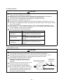
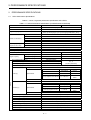
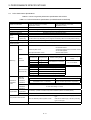
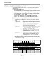
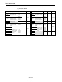
Store and use the unit in the following environmental conditions.
Environment
Ambient
temperature
Ambient humidity
Storage
temperature
Atmosphere
Altitude
Vibration
Conditions
Control unit/servo amplifier
Servomotor
0°C to +55°C
0°C to +40°C
(With no freezing)
(With no freezing)
According to each instruction
80%RH or less
manual.
(With no dew condensation)
According to each instruction
−20°C to +65°C
manual.
Indoors (where not subject to direct sunlight).
No corrosive gases, flammable gases, oil mist or dust must exist.
1000m or less above sea level.
According to each instruction manual.
−V−
! CAUTION
When coupling with the synchronization encoder or servomotor shaft end, do not apply
impact such as by hitting with a hammer. Doing so may lead to detector damage.
Do not apply a load larger than the tolerable load onto the servomotor shaft. Doing so may
lead to shaft breakage.
When not using the unit for a long time, disconnect the power line from the control unit or
servo amplifier.
Place the control unit and servo amplifier in static electricity preventing vinyl bags and store.
When storing for a long time, contact the Service Center or Service Station.
(4) Wiring
! CAUTION
Correctly and securely wire the wires. Reconfirm the connections for mistakes and the
terminal screws for tightness after wiring. Failing to do so may lead to run away of the
servomotor.
After wiring, install the protective covers such as the terminal covers to the original
positions.
Do not install a phase advancing capacitor, surge absorber or radio noise filter (option FRBIF) on the output side of the servo amplifier.
Correctly connect the output side (terminals U, V, W). Incorrect connections will lead the
servomotor to operate abnormally.
Do not connect a commercial power supply to the servomotor, as this may lead to trouble.
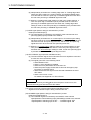
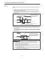
Do not mistake the direction of the surge absorbing diode
Servo amplifier
installed on the DC relay for the control signal output of
VIN
(24VDC)
brake signals, etc. Incorrect installation may lead to signals
not being output when trouble occurs or the protective
functions not functioning.
Control output
signal
RA
Do not connect or disconnect the connection cables
between each unit, the encoder cable or sequence expansion cable while the power is ON.
Securely tighten the cable connector fixing screws and fixing mechanisms. Insufficient fixing
may lead to the cables combing off during operation.
Do not bundle the power line or cables.
(5) Trial operation and adjustment
! CAUTION
Confirm and adjust the program and each parameter before operation. Unpredictable
movements may occur depending on the machine.
Extreme adjustments and changes may lead to unstable operation, so never make them.
When using the absolute position system function, on starting up, and when the controller or
absolute value motor has been replaced, always perform a home position return.
− VI −
(6) Usage methods
! CAUTION
Immediately turn OFF the power if smoke, abnormal sounds or odors are emitted from the
control unit, servo amplifier or servomotor.
Always execute a test operation before starting actual operations after the program or
parameters have been changed or after maintenance and inspection.
The units must be disassembled and repaired by a qualified technician.
Do not make any modifications to the unit.
Keep the effect or magnetic obstacles to a minimum by installing a noise filter or by using
wire shields, etc. Magnetic obstacles may affect the electronic devices used near the control
unit or servo amplifier.
When using the CE mark-compatible equipment, refer to "EMC Installation Guidelines" (data
number IB(NA)-*****-*) for the motion controller and to the corresponding EMC guideline data for
the servo amplifier, inverter and other equipment.
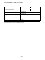
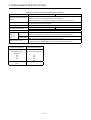
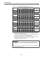
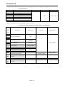
Use the units with the following conditions.
Item
Input power
Input frequency
Tolerable momentary
power failure
Conditions
According to A172SHCPUN/A171SHCPUN/
A273UHCPU/A173UHCPU(S1) user’s
manual.
According to A172SHCPUN/A171SHCPUN/
A273UHCPU/A173UHCPU(S1) user’s
manual.
According to A172SHCPUN/A171SHCPUN/
A273UHCPU/A173UHCPU(S1) user’s
manual.
(7) Remedies for errors
! CAUTION
If an error occurs in the self diagnosis of the control unit or servo amplifier, confirm the
check details according to the instruction manual, and restore the operation.
If a dangerous state is predicted in case of a power failure or product failure, use a
servomotor with magnetic brakes or install a brake mechanism externally.
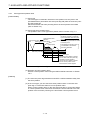
Use a double circuit construction so that the
magnetic brake operation circuit can be
Shut off with the
operated by emergency stop signals set
emergency stop
Shut off servo ON signal OFF,
signal (EMG).
alarm, magnetic brake signal.
externally.
If an error occurs, remove the cause, secure
Servo motor
RA1
EMG
the safety and then resume operation.
Magnetic
The unit may suddenly resume operation
24VDC
brakes
after a power failure is restored, so do not go
near the machine. (Design the machine so
that personal safety can be ensured even if
the machine restarts suddenly.)
− VII −
(8) Maintenance, inspection and part replacement
! CAUTION
Perform the daily and periodic inspections according to the instruction manual.
Perform maintenance and inspection after backing up the program and parameters for the
control unit and servo amplifier.
Do not place fingers or hands in the clearance when opening or closing any opening.
Periodically replace consumable parts such as batteries according to A172SHCPUN/
A171SHCPUN user's manual, A273UHCPU user’s manual, A173UHCPU(S1) user’s manual or
the instruction manual for the product you are using.
! CAUTION
Do not touch the lead sections such as ICs or the connector contacts.
Do not place the control unit or servo amplifier on metal that may cause a power leakage or
wood, plastic or vinyl that may cause static electricity buildup.
Do not perform a megger test (insulation resistance measurement) during inspection.
When replacing the control unit or servo amplifier, always set the new unit settings correctly.
When the controller or absolute value motor has been replaced, carry out a home position
return operation using one of the following methods, otherwise position displacement could
occur.
1) After writing the servo data to the PC using peripheral device software, switch on the
power again, then perform a home position return operation.
2) Using the backup function of the peripheral device software, load the data backed up
before replacement.
After maintenance and inspections are completed, confirm that the position detection of the
absolute position detector function is correct.
Do not short circuit, charge, overheat, incinerate or disassemble the batteries.
The electrolytic capacitor will generate gas during a fault, so do not place your face near the
control unit or servo amplifier.
The electrolytic capacitor and fan will deteriorate. Periodically change these to prevent
secondary damage from faults. Replacements can be made by the Service Center or
Service Station.
(9) Disposal
! CAUTION
Dispose of this unit as general industrial waste.
Do not disassemble the control unit, servo amplifier or servomotor parts.
Dispose of the battery according to local laws and regulations.
− VIII −
(10) General cautions
! CAUTION
All drawings provided in the instruction manual show the state with the covers and safety
partitions removed to explain detailed sections. When operating the product, always return
the covers and partitions to the designated positions, and operate according to the
instruction manual.
− IX −
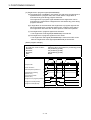
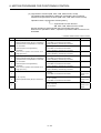
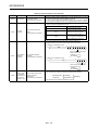
Revisions
*The manual number is given on the bottom left of the back cover.
Print Date
*Manual Number
Revision
Feb., 2000 IB(NA)-0300014-A First edition
This manual confers no industrial property rights or any rights of any other kind, nor does it confer any patent
licenses. Mitsubishi Electric Corporation cannot be held responsible for any problems involving industrial
property rights which may occur as a result of using the contents noted in this manual.
© 2000 Mitsubishi Electric Corporation
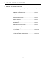
CONTENTS
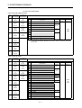
1. GENERAL DESCRIPTION....................................................................................................... 1- 1 to 1-17
1.1 System Configuration .......................................................................................................................
1.1.1 A172SHCPUN system overall configuration .............................................................................
1.1.2 A171SHCPUN system overall configuration .............................................................................
1.1.3 A273UHCPU (32 axis feature) system overall configuration.....................................................
1.1.4 A173UHCPU (S1) system overall configuration ........................................................................
1.1.5 System configuration precautions .............................................................................................
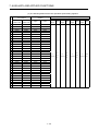
1.2 Table of Software Package ..............................................................................................................
1.3 Positioning Control by the Servo System CPU ................................................................................
1- 3
1- 3
1- 4
1- 5
1- 6
1- 7
1- 9
1- 9
2. PERFORMANCE SPECIFICATIONS ...................................................................................... 2- 1 to 2-10
2.1 SCPU Performance Specifications .................................................................................................. 2- 1
2.2 PCPU Performance Specifications .................................................................................................. 2- 5
2.3 The Differences between A172SHCPUN/A171SHCPUN and A171S (S3) and the Differences between
A273UHCPU (32 axis feature) and A173UHCPU (S1) .................................................................. 2- 9
2.3.1 The differences between A172SHCPUN/A171SHCPUN and A171S(S3) ................................ 2- 9
2.3.2 The differences between A273UHCPU and A173UHCPU (S1)................................................ 2-10
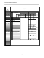
3. POSITIONING SIGNALS ......................................................................................................... 3- 1 to 3-79
3.1 Internal Relays ................................................................................................................................. 3- 2
3.1.1 Axis status ................................................................................................................................ 3-13
3.1.2 Axis command signals.............................................................................................................. 3-24
3.1.3 Common devices...................................................................................................................... 3-35
3.2 Data Registers ................................................................................................................................ 3-41
3.2.1 Axis monitor devices................................................................................................................. 3-50
3.2.2 Control change registers .......................................................................................................... 3-55
3.2.3 Tool length offset data .............................................................................................................. 3-56
3.2.4 Common device ....................................................................................................................... 3-57
3.2.4.1 A172SHCPUN/A171SHCPUN .............................................................................................. 3-57
3.2.4.2 A273UHCPU (32 axis feature)/A173UHCPU (S1) ................................................................ 3-60
3.3 Special Relays (SP.M) .................................................................................................................... 3-65
3.4 Special Registers (SP.D) ................................................................................................................ 3-68
3.4.1 A172SHCPUN/A171SHCPUN ................................................................................................. 3-68
3.4.2 A273UHCPU (32 axis feature)/A173UHCPU (S1) ................................................................... 3-76
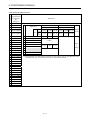
4. PARAMETERS FOR POSITIONING CONTROL .................................................................... 4- 1 to 4-35
4.1 System Settings ...............................................................................................................................
4.2 Fixed Parameters.............................................................................................................................
4.2.1 Setting the number of pulses per revolution/travel value per revolution/unit magnification.......
4.2.2 Upper stroke limit value/lower stroke limit value .......................................................................
4.2.3 Command in-position range ......................................................................................................
4.2.4 Rapid feedrate setting ...............................................................................................................
−I−
4- 2
4- 3
4- 4
4- 6
4- 7
4- 8
4.3 Servo Parameters ............................................................................................................................ 4- 9
4.3.1 MR- -B servo parameters..................................................................................................... 4-10
4.3.2 Position control gain 1, 2 .......................................................................................................... 4-15
4.3.3 Speed control gain 1, 2............................................................................................................. 4-16
4.3.4 Speed integral compensation ................................................................................................... 4-17
4.3.5 In-position range....................................................................................................................... 4-17
4.3.6 Feed forward gain..................................................................................................................... 4-17
4.3.7 Load inertia ratio....................................................................................................................... 4-18
4.3.8 Automatic tuning....................................................................................................................... 4-18
4.3.9 Servo responsiveness setting................................................................................................... 4-19
4.3.10 Notch filter .............................................................................................................................. 4-20
4.3.11 Electromagnetic brake sequence ........................................................................................... 4-20
4.3.12 Monitor output mode............................................................................................................... 4-20
4.3.13 Optional function 1.................................................................................................................. 4-20
4.3.14 Optional function 2.................................................................................................................. 4-21
4.3.15 Monitor output 1, 2 offset........................................................................................................ 4-22
4.3.16 Pre-alarm data selection......................................................................................................... 4-23
4.3.17 Zero speed ............................................................................................................................. 4-23
4.3.18 Excessive error alarm level .................................................................................................... 4-23
4.3.19 Optional function 5.................................................................................................................. 4-23
4.3.20 PI-PID switching position droop.............................................................................................. 4-24
4.3.21 Torque control compensation factor....................................................................................... 4-24
4.3.22 Speed differential compensation ............................................................................................ 4-24
4.4 Home Position Return Data ............................................................................................................ 4-25
4.5 JOG Operation Data ....................................................................................................................... 4-27
4.6 Parameter Block.............................................................................................................................. 4-28
4.6.1 Relationships among the speed limit value, acceleration time,
deceleration time, and rapid stop deceleration time ............................................................... 4-31
4.6.2 S curve ratio ............................................................................................................................. 4-33
4.6.3 Allowable error range for circular interpolation ......................................................................... 4-34
4.7 Work Coordinate Data .................................................................................................................... 4-35
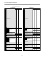
5. SEQUENCE PROGRAMS AND SFC PROGRAMS ................................................................ 5- 1 to 5-26
5.1 Cautions on Creating a Sequence Program or SFC Program ......................................................... 5- 1
5.2 Motion Program Start Request Instruction (DSFRP/SVST) ............................................................. 5- 2
5.2.1 Start request instruction for 1 to 3 axes (DSFRP): when using A172SHCPUN/A171SHCPUN
................................................................................................................................................... 5- 2
5.2.2 Start request instruction for 1 to 8/1 to 4 axes (SVST).............................................................. 5- 5
5.3 Home Position Return Instructions (DSFLP/CHGA) ........................................................................ 5- 8
5.3.1 DSFLP instruction: when using A172SHCPUN/A171SHCPUN ................................................ 5- 8
5.3.2 CHGA instruction...................................................................................................................... 5-10
5.4 Speed Change Instructions (DSFLP/CHGV) .................................................................................. 5-12
5.4.1 DSFLP instruction (When using A172SHCPUN/A171SHCPUN)............................................. 5-12
5.4.2 CHGV instruction...................................................................................................................... 5-15
5.5 Moving Backward during Positioning .............................................................................................. 5-18
5.6 CHGT instruction............................................................................................................................. 5-20
− II −
5.7 SFC Programs ................................................................................................................................ 5-22
5.7.1 Starting and stopping SFC programs ....................................................................................... 5-22
5.7.2 Motion program start request ................................................................................................... 5-23
6. MOTION PROGRAMS FOR POSITIONING CONTROL....................................................... 6- 1 to 6-133
6.1 Motion Program Makeup.................................................................................................................. 6- 1
6.2 Instructions for Creating Motion Programs ...................................................................................... 6- 4
6.3 G Code List ...................................................................................................................................... 6- 8
6.4 Special M Code List ......................................................................................................................... 6- 9
6.5 Instruction Symbol/Character List ................................................................................................... 6-10
6.6 Method for Setting Positioning Data................................................................................................ 6-12
6.6.1 Direct designation (numerical value) ........................................................................................ 6-12
6.6.2 Indirect designation (variable: #****) ......................................................................................... 6-12
6.6.3 About operational data ............................................................................................................. 6-19
6.6.4 Instruction symbol setting range list ......................................................................................... 6-28
6.6.5 Positioning control unit for 1 axis............................................................................................... 6-30
6.6.6 Control units for interpolation control........................................................................................ 6-30
6.6.7 Control in the control unit of “degree” ....................................................................................... 6-32
6.7 About Coordinate Systems.............................................................................................................. 6-34
6.8 G Code ............................................................................................................................................ 6-35
6.8.1 G00 PTP positioning at rapid feedrate ..................................................................................... 6-38
6.8.2 G01 CP positioning at speed specified in F.............................................................................. 6-40
6.8.3 G02 Circular interpolation CW (Circular arc center coordinate designation) ........................... 6-42
6.8.4 G03 Circular interpolation CCW (Circular arc center coordinate designation)......................... 6-44
6.8.5 G02 Circular interpolation CW (Radius designation)................................................................ 6-46
6.8.6 G03 Circular interpolation CCW (Radius designation) ............................................................. 6-48
6.8.7 G04 Dwell ................................................................................................................................. 6-50
6.8.8 G09 Exact stop check .............................................................................................................. 6-52
6.8.9 G23 Cancel, cancel start invalidity............................................................................................ 6-54
6.8.10 G24 Cancel, cancel start ........................................................................................................ 6-56
6.8.11 G25 High-speed oscillation..................................................................................................... 6-58
6.8.12 G26 High-speed oscillation stop............................................................................................. 6-60
6.8.13 G28 Home position return ...................................................................................................... 6-62
6.8.14 G30 Second home position return........................................................................................... 6-64
6.8.15 G32 Skip................................................................................................................................. 6-66
6.8.16 G43 Tool length offset (+)....................................................................................................... 6-70
6.8.17 G44 Tool length offset (-) ....................................................................................................... 6-72
6.8.18 G49 Tool length offset cancel................................................................................................. 6-74
6.8.19 G53 Mechanical coordinate system selection ........................................................................ 6-76
6.8.20 G54 to G59 Work coordinate system selection....................................................................... 6-78
6.8.21 G61 Exact stop check mode ................................................................................................... 6-80
6.8.22 G64 Cutting mode .................................................................................................................. 6-82
6.8.23 G90 Absolute value command ............................................................................................... 6-84
6.8.24 G91 Incremental value command .......................................................................................... 6-86
6.8.25 G92 Coordinate system setting .............................................................................................. 6-88
6.8.26 G100, G101 Time-fixed acceleration/deceleration, acceleration-fixed acceleration/deceleration
switching instructions ........................................................................................................... 6-90
− III −
6.9 M Code............................................................................................................................................ 6-92
6.10 Special M Code ............................................................................................................................. 6-92
6.10.1 M00 Program stop .................................................................................................................. 6-93
6.10.2 M01 Optional program stop .................................................................................................... 6-95
6.10.3 M02 Program end................................................................................................................... 6-97
6.10.4 M30 Program end................................................................................................................... 6-99
6.10.5 M98, M99 Subprogram call, subprogram end ...................................................................... 6-101
6.10.6 M100 Preread inhibit ............................................................................................................. 6-103
6.11 Miscellaneous.............................................................................................................................. 6-105
6.11.1 Program control function (IF, GOTO statement) .................................................................. 6-106
6.11.2 Program control function (IF, THEN, ELSE, END statements) ............................................ 6-108
6.11.3 WHILE DO statement........................................................................................................... 6-110
6.11.4 Four fundamental operators, assignment operator (+, -, *, /, MOD, =) ................................ 6-112
6.11.5 Trigonometric functions (SIN, COS, TAN, ASIN, ACOS, ATAN) ......................................... 6-114
6.11.6 Real number to BIN value conversion (INT)......................................................................... 6-116
6.11.7 BIN value to real number conversion (FLT) ......................................................................... 6-118
6.11.8 Functions (SQRT, ABS, BIN, BCD, LN, EXP, RND, FIX, FUP) ........................................... 6-120
6.11.9 Logical operators (AND, OR, XOR, NOT, <<, >>)................................................................ 6-122
6.11.10 Move block wait functions (WAITON, WAITOFF) .............................................................. 6-124
6.11.11 Parameter block change (PB) ............................................................................................ 6-126
6.11.12 Torque limit value change (TL)............................................................................................ 6-128
6.11.13 Bit device set, reset functions (SET, RST) ......................................................................... 6-130
6.11.14 Conditional branch using bit device (ON, OFF).................................................................. 6-132
7. AUXILIARY AND APPLIED FUNCTIONS................................................................................ 7- 1 to 7-52
7.1 Limit Switch Output Function ........................................................................................................... 7- 2
7.1.1 Limit switch output data ............................................................................................................. 7- 2
7.1.2 Limit switch output function ....................................................................................................... 7- 2
7.2 Backlash Compensation Function.................................................................................................... 7- 4
7.3 Torque Limit Function ...................................................................................................................... 7- 6
7.3.1 Torque limit value changing function ......................................................................................... 7- 6
7.4 Electronic Gear Function.................................................................................................................. 7- 8
7.5 Absolute Positioning System........................................................................................................... 7-10
7.6 Home Position Return ..................................................................................................................... 7-13
7.6.1 Near-zero point dog type home position return ........................................................................ 7-13
7.6.2 Count type home position return .............................................................................................. 7-15
7.6.3 Data setting type home position return..................................................................................... 7-16
7.6.4 Execution of home position return............................................................................................ 7-17
7.7 Speed Change ................................................................................................................................ 7-19
7.8 JOG Operation ................................................................................................................................ 7-23
7.8.1 Individual start .......................................................................................................................... 7-23
7.8.2 Simultaneous start.................................................................................................................... 7-27
7.9 Manual Pulse Generator Operation ................................................................................................ 7-31
7.10 Override Ratio Setting Function .................................................................................................... 7-40
7.11 FIN Signal Waiting Function.......................................................................................................... 7-43
7.12 Single Block................................................................................................................................... 7-47
7.13 Enhanced Present Value Control .................................................................................................. 7-51
7.14 High-Speed Reading of Designated Data ..................................................................................... 7-52
− IV −
APPENDICES ......................................................................................................................APP- 1 to APP-79
APPENDIX 1 SCPU ERROR CODE LIST ......................................................................................... APP- 1
Appendix 1.1 SCPU Error Code List .............................................................................................. APP- 1
APPENDIX 2 ERROR CODES STORED BY THE PCPU ................................................................. APP- 5
Appendix 2.1 Motion Program Setting Errors ................................................................................. APP- 7
Appendix 2.2 Minor Errors.............................................................................................................. APP- 8
Appendix 2.3 Major Errors............................................................................................................. APP-16
Appendix 2.4 Servo Errors ............................................................................................................ APP-19
Appendix 2.5 PC Link Communication Errors ............................................................................... APP-33
Appendix 2.6 LED Indications When Errors Occur at the PCPU .................................................. APP-34
APPENDIX 3 SPECIAL RELAYS AND SPECIAL REGISTERS ....................................................... APP-37
Appendix 3.1 Special Relays (SP.M)............................................................................................. APP-37
Appendix 3.2 Special Registers (SP.D)......................................................................................... APP-40
APPENDIX 4 EXAMPLE PROGRAMS ............................................................................................. APP-51
Appendix 4.1 Word Data 1 Word Shift to Left ............................................................................... APP-51
Appendix 4.2 Word Data 1 Word Shift to Right............................................................................. APP-53
Appendix 4.3 Reading M Codes.................................................................................................... APP-55
Appendix 4.4 Error Code Reading................................................................................................. APP-56
Appendix 4.5 Magnitude Comparison and Four Fundamental Operations of 32-Bit Monitor Data
................................................................................................................................ APP-57
APPENDIX 5 SERVO MOTOR TYPE-BASED RATED SPEED AND FEEDBACK PULSE COUNT LIST
.................................................................................................................................... APP-59
APPENDIX 6 PROCESSING TIMES ................................................................................................ APP-60
−V−
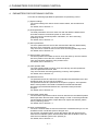
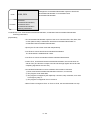
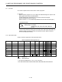
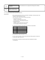
1. GENERAL DESCRIPTION
1. GENERAL DESCRIPTION
This manual describes the positioning control parameters, positioning-dedicated
devices, positioning methods and other information required to execute positioning
control with the motion controller (SV43). The motion controller (SV43) uses the
NC language (EIA) (hereafter referred to as the "motion program") as a
programming language.
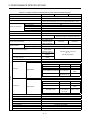
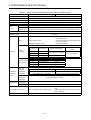
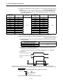
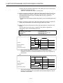
The motion controller (SV43) can exercise the following positioning control.
Number of Axes Controlled in
Positioning Control
Applicable CPU
A172SHCPUN
8
A171SHCPUN
4
A273UHCPU (32 axis feature)
32
A173UHCPU(S1)
32
In this manual, the above CPUs are collectively referred to as the "servo system
CPUs".
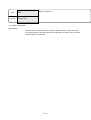
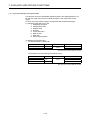
The following software packages are used to make system settings, and to set,
test and monitor the servo parameters and motion programs.
• SW2SRX-GSV43P software package
....................... Abbreviated to "GSV43P"
• SW2NX-GSV43P software package
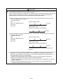
! CAUTION
When designing the system, provide external protective and safety circuits to ensure safety in the
event of trouble with the motion controller.
There are electronic components which are susceptible to the effects of static electricity mounted
on the printed circuit board. When handling printed circuit boards with bare hands you must
ground your body or the work bench.
Do not touch current-carrying or electric parts of the equipment with bare hands.
Make parameter settings within the ranges stated in this manual.
Use the program instructions that are used in programs in accordance with the conditions
stipulated in this manual.
Some devices for use in programs have fixed applications: they must be used in accordance with
the conditions stipulated in this manual.
1−1
1. GENERAL DESCRIPTION
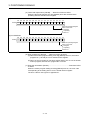
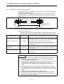
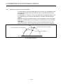
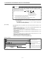
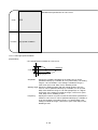
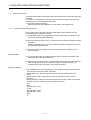
Conventions Used in this Manual
Positioning signals are always indicated in the following order: signal for
A172SHCPUN signal for A171SHCPUN signal for A273UHCPU (32 axes
feature) signal for A173UHCPU(S1). If only one positioning signal is indicated,
this means that the signal is used in common by every CPUs.
The explanatory text is written with reference to the A172SHCPU: if you are not
using an A172SHCPUN, the positioning signals should be read as the positioning
signals for the CPU you are using.
(For the positioning signals used with each CPU, refer to Appendix 6.)
A172SHCPUN/A171SHCPUN
A273UHCPU (32 axis feature) /A173UHCPU(S1)
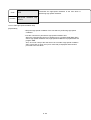
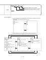
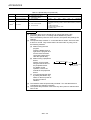
3. POSITIONING SIGNALS
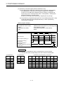
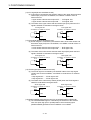
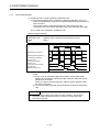
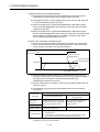
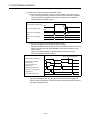
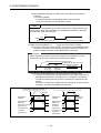
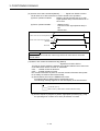
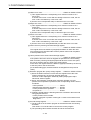
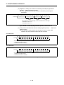
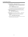
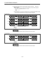
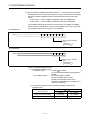
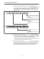
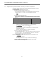
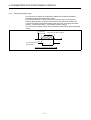
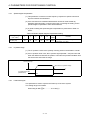
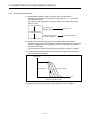
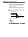
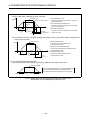
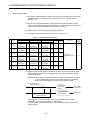
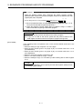
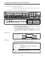
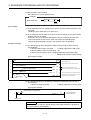
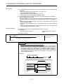
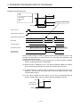
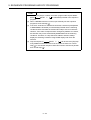
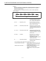
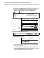
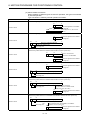
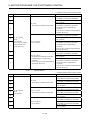
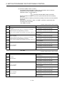
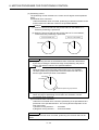
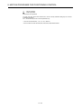
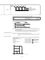
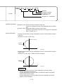
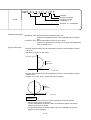
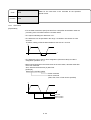
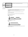
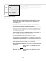
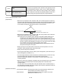
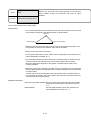
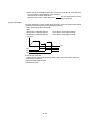
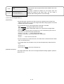
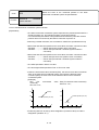
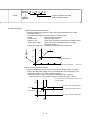
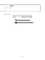
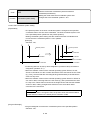
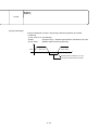
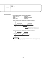
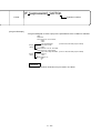
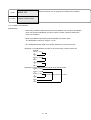
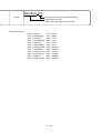
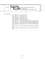
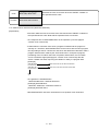
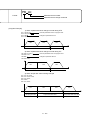
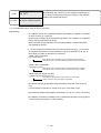
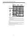
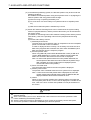
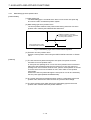
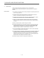
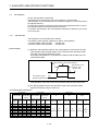
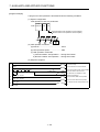
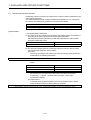
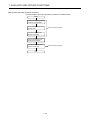
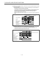
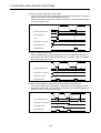
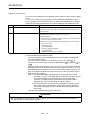
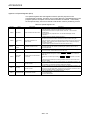
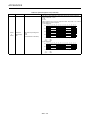
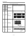
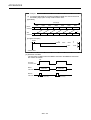
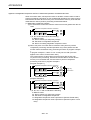
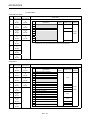
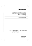
3.1.24 Error reset command (M1807+20n/M3207+20n)
(1) The error reset command is used to clear the minor error code or major error
code storage area of an axis for which the error detection signal has come ON
(M1607+20n), and to reset the error detection signal (M1607+20n).
ON
Error detection (M1607+20n)
OFF
ON
Error reset (M1807+20n)
OFF
Minor error code storage
area
**
00
Major error code storage
area
**
00
* *: Error code
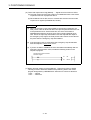
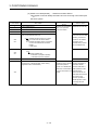
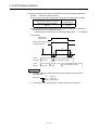
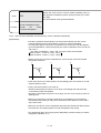
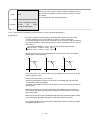
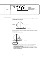
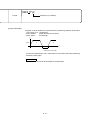
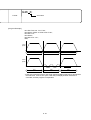
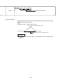
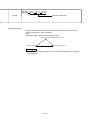
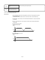
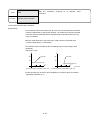
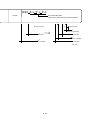
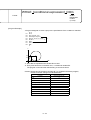
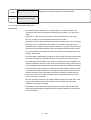
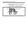
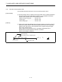
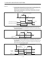
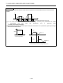
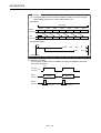
(2) The motion program running status is reset if the error is reset during a
temporary stop (M1403+10n) made by the stop command (M1800+20n) during
an automatic start or if the error is reset during a block stop made by M00/M01.
Block stop made by M00/M01
Start acceptance (M2001+n)
Automatically operating
(M1402+10n)
Temporary stopping (M1403+10n)
DSFRP/SVST instruction
Temporary stop instruction
(M1500+10n)
Error reset (M1807+20n)
OFF
ON
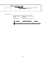
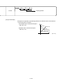
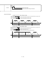
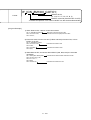
(3) When the error reset command is switched on during automatic operation
(M1402+10n ON), the above reset processing is performed after stop processing
is executed under the temporary stop command (M1500+10n).
3 - 19
1−2
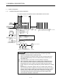
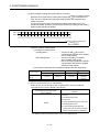
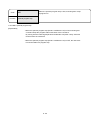
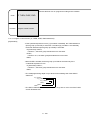
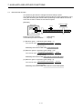
1. GENERAL DESCRIPTION
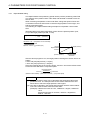
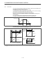
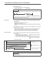
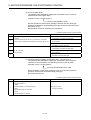
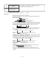
1.1
System Configuration
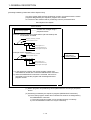
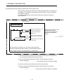
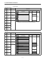
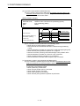
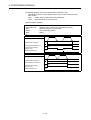
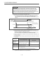
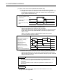
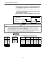
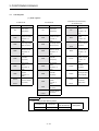
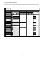
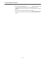
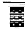
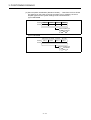
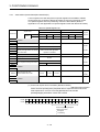
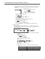
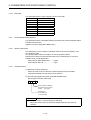
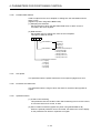
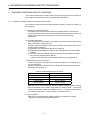
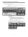
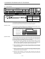
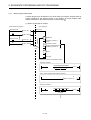
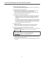
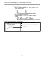
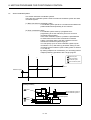
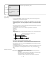
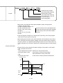
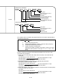
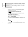
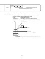
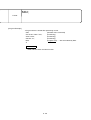
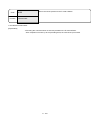
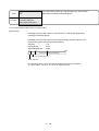
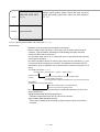
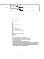
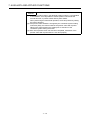
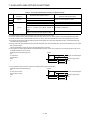
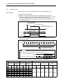
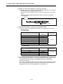
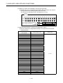
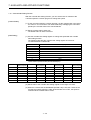
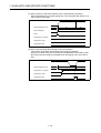
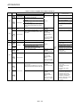
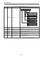
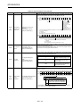
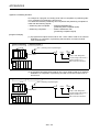
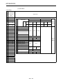
1.1.1
A172SHCPUN system overall configuration
An example system configuration with A172SHCPUN is shown below.
A6BAT
A172SHCPUN A172S A1S
ENC
Y42
A1S I/O module or
Special function module
Emergency stop input
PC extension base
unit extension cable
(A1SC B for A1S6 B
Main base unit
(A178B-S1/A17 B) and A168B)
(A1S NB for A6 B)
P Manual pulse generator 1
(MR-HDP01)
Synchronous encoder cable 1
(MR-HSCBL M)
E Synchronous encoder 1
(MR-HENC)
100/200VAC
PC (DOS/V)
RS422
Power supply module
Battery
Sequencer slot
Limit swith output
module
Manual pulse
generator/synchronous
encoder interface module
Motor slot
PC extension unit
Up to one extension base unit for A1S6 B
Up to one extension base unit for A168B(GOT compatible)
Up to one extension bese unit for A6 B
External input signals
FLS
RLS
STOP
DOG/CHANGE
Communication cable
(A270CDCBL M/A270BDCBL M)
PC (DOS/V)
TREN
SSCNET2
Upper limit LS
Lower limit LS
Stop signal
8
Near-zero point dog/change
over between speed and position
Tracking
1
Brake output
SSCNET interface card/board
(A30CD-PCF/A30BD-PCF)
Motion net cable
d1
SSCNET1
d2
d3
d8
Termination resistance
M
E
M
E
M
E
M
E
MR-H-B/MR-J2-B/MR-J-B
servo amplifiers Max. 8 axes
NOTES
(1) When using the PC extension base and bus connection type GOT,
choose the A168B as the PC extension base.
When not using the PC extension base, the bus connection type GOT
can be connected directly to the PC extension base connector of the
main base unit.
(2) Use motion slots to mount PC A1S I/O modules if necessary.
(3) When the power supply to the servo system CPU is switched ON and
OFF, erroneous process outputs may temporarily be made due to the
delay between the servo system CPU power supply and the external
power supply for processing (especially DC), and the difference in startup
times.
For example, if the power supply to the servo system CPU comes ON
after the external power supply for processing comes ON at a DC output
module, the DC output module may temporarily give erroneous outputs
when the power to the servo system CPU comes ON. Accordingly a
circuit that ensures that the power supply to the servo system CPU
comes ON first should be constructed.
1−3
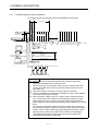
1. GENERAL DESCRIPTION
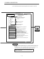
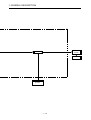
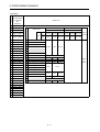
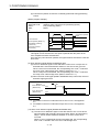
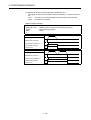
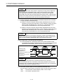
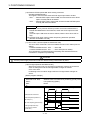
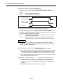
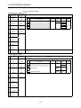
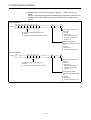
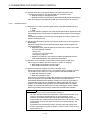
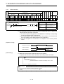
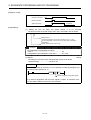
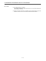
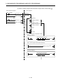
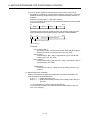
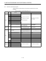
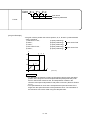
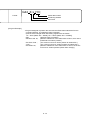
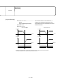
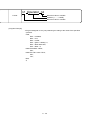
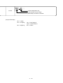
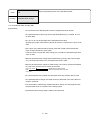
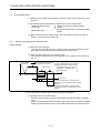
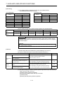
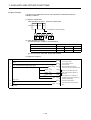
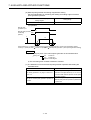
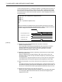
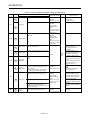
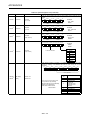
1.1.2
A171SHCPUN system overall configuration
An example system configuration with A171SHCPUN is shown below.
A6BAT
A171SHCPUN A172S A1S
ENC
Y42
Power supply module
Battery unit
Sequencer slot
Limit swith output
module
Manual pulse
generator/synchronous
encoder interface module
Motor slot
A1S I/O module or
Special function module
Emergency stop input
PC extension base
unit extension cable
(A1SC B for A1S6 B PC extension unit
Main base unit
(A178B-S1/A17 B) and A168B)
Up to one extension base unit for A1S6 B
P Manual pulse generator 1
(A1S NB for A6 B)
Up to one extension base unit for A168B(GOT compatible)
(MR-HDP01)
Up to one extension bese unit for A6 B
Synchronous encoder cable 1
(MR-HSCBL M)
E Synchronous encoder 1
(MR-HENC)
100/200VAC
PC (DOS/V)
RS422
Communication cable
(A270CDCBL M/A270BDCBL
PC (DOS/V)
External input signals
FLS
RLS
STOP
DOG/CHANGE
M)
TREN
SSCNET2
Upper limit LS
Lower limit LS
Stop signal
Near-zero point dog/speed/
position switching
Tracking
4
1
Brake output
SSCNET interface card/board Motion net cable
(A30CD-PCF/A30BD-PCF)
d1
SSCNET1
d2
d3
d4
Termination resistance
M
E
M
E
M
E
M
E
MR-H-B/MR-J2-B/MR-J-B
Servo amplifiers MAX.4 axes
NOTES
(1) When using the PC extension base and bus connection type GOT,
choose the A168B as the PC extension base.
When not using the PC extension base, the bus connection type GOT
can be connected directly to the PC extension base connector of the
main base unit.
(2) Use motion slots to mount PC A1S I/O modules if necessary.
(3) Though A172SENC has external input signals for 8 axes, make settings
for the first 4 axes (PXO to PXOF).
(4) When the power supply to the servo system CPU is switched ON and
OFF, erroneous process outputs may temporarily be made due to the
delay between the servo system CPU power supply and the external
power supply for processing (especially DC), and the difference in startup
times.
For example, if the power supply to the servo system CPU comes ON
after the external power supply for processing comes ON at a DC output
module, the DC output module may temporarily give erroneous outputs
when the power to the servo system CPU comes ON. Accordingly a
circuit that ensures that the power supply to the servo system CPU
comes ON first should be constructed.
1−4
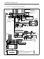
1. GENERAL DESCRIPTION
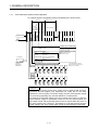
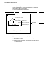
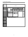
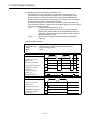
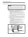
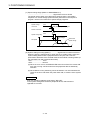
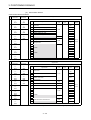
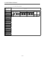
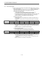
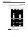
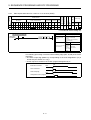
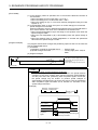
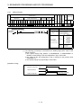
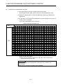
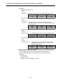
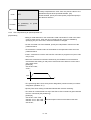
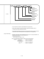
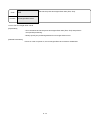
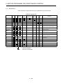
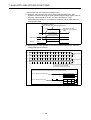
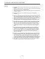
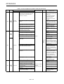
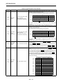
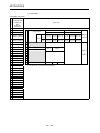
1.1.3
A273UHCPU (32 axis feature) system overall configuration
0
0
0
0
1
2
3
4
0
MR-RB30
MR-RB50
A300RU-50
EMG
External input signals (5 points)
FLS Upper LS
RLS Lower LS
STOP Stop signal
DOG Near-zero point dog
CHANGE Speed position change
DB COMDB IN-
100/200VAC
M
E
Motion network cable
(between CPU and
separated amplifier)
MR-JBUS M
MR-J2HBUS M-A
3-phase power supply
200V
DB OUTDB IN+
EMG
Emergency
stop
0
Set the line information (wiring information) of:
Servo power supply module (A230P),
Regenerative brake resistor AC motor drive module,
A278LX (brake output) and
MR-RB064
A240DY
MR-RB10
in "System settings".
A62P A273UHCPU A278 A240 A221 A211 A222AM-20 A230P
LX
DY
AM-20 AM-20
BRAKE
Brake output
AC motor drive
module
(ADU)
M
E
M
E
M
E
MR-HCBL M
MR-HSCBL M
Up to 16 axes
(Up to 32 axes including those
of separated amplifiers)
M
E
SSCNET1
Separated amplifier (MR-H-B/MR-J-B/MR-J2-B servo amplifier)
d2
d8
0
1
7
Termination
connector
MR-TM/MR-A-TM
MR-HCBL M
M
MR-HSCBL M E
MR-JCCBL M
MR-JHSCBL M
HA-*H series motor
HC-MF series motor
HA-FF series motor
HA-SF series motor
M
E
M
E
SSCNET2
Up to 8 axes/network, up to a total of 32 axes
( Up to 32 axes including those of ADUs)
MELSECNET(II)
MELSECNET/B
MELSECNET/10
PC extension base
(A68B/A65B/A62B)
HA-*H series motor (ABS and incremental systems may be mixed)
d1
8
1
Sequencer module
d1
d2
d8
0
1
7
Network module
MR-JBAT
4,8,8 n
Servo power supply
module line number
Servo
power
supply
module
Power supply module
Battery unit
(ADU(ABS))
Servo external
signal module
Dynamic brake
module
<Main base unit>
A278B/A275B
CPU module
Control power supply
module
The system configuration example of the motion controller (SV43) is shown below.
MR-JBAT
SSCNET3
Limit switch output module
SSCNET4
Man-machine
control module
Pulse generator/synchronous
encoder interface module
<Motion extension base>
A268B/A255B
d1
d2
d8
0
1
7
M
E
M
E
M
E
M
E
M
E
M
E
Battery unit
Needed when using MR-J-B(ABS)
Needed for each network
d1
d2
d8
0
1
7
MR-JBAT
M
E
1
1
1
1
M
E
M
E
1
A62P A271 A273 AY42 A278 A221 A211 A230P
DVP EX
LX AM AM
Servo power supply module line number
Limit output
64 points
P
1
Manual pulse generator (INC)
Motion network cable
(between separated amplifier)
MR-HBUS M
MR-J2HBUS M-A
MR-J2HBUS M
3
External input signal
3
TREN tracking enable
AX
AY
Motion module
PC I/O modules
2
4
Up to four extension bases
The I/O numbers of the "PC I/O modules" loaded into the main and
motion extension bases should be assigned to higher than those
used in the PC extension. (Set in "System settings")
PC special modules must not be loaded.
1−5
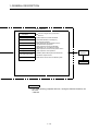
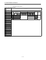
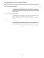
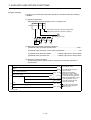
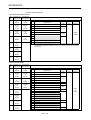
1. GENERAL DESCRIPTION
A173UHCPU(S1) system overall configuration
An example system configuration with A173UHCPU(S1) is shown below.
PC input module
A173UHCPU A172S A172S
ENC
ENC
Sequencer slot
Limit swith output
module
Manual pulse
generator/synchronous
encoder
Motor slot
external signal
input module
1.1.4
A1S
Y42
A1S
Y41
PC I/O module
A1S
6 P
AnS I/O module or
Special function module
Emergency stop
100/200VAC
AnS I/O module or
Special function module
Main base unit
(A178B-S2)
P Manual pulse generator
(MR-HDP01)
PC extension base: A1S6 B/A168B
1 extension base can be increased *1.
A172SENC: Up to 4 modules usable
1
When 4 modules are used
External input signals of 32
axes can be entered.
Tracking enable inputs of 4 points
3 manual pulse generators usable
Brake output of 1 point
(all axes in batch)
External input signals
FLS
RLS
STOP
DOG/CHANGE
PC (DOS/V)
TREN
SSCNET
Upper limit LS
Lower limit LS
Stop signal
Near-zero point dog/speed/
position switching
Tracking
8
1
Brake output
SSCNET interface
card/board
(A30CD-PCF
/A30BD-PCF)
MR-J2-B/MR-H-B(N) (up to 8 axes per SSCNET line)
*1: Use A168B when using PC
extension base and connecting
GOT by bus connection.
SSCNET1
M
E
M
E
M
E
M
E
M
E
M
E
M
E
M
E
M
E
M
E
M
E
M
E
M
E
M
E
M
E
M
E
SSCNET2
SSCNET3
SSCNET4
NOTES
When the power supply to the servo system CPU is switched ON and OFF,
erroneous process outputs may temporarily be made due to the delay
between the servo system CPU power supply and the external power supply
for processing (especially DC), and the difference in startup times.
For example, if the power supply to the servo system CPU comes on after the
external power supply for processing comes on at a DC output module, the
DC output module may temporarily give erroneous outputs when the power to
the servo system CPU comes on. Accordingly a circuit that ensures that the
power supply to the servo system CPU comes on first should be constructed.
1−6
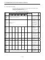
1. GENERAL DESCRIPTION
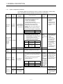
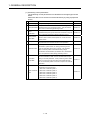
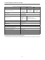
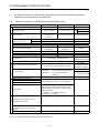
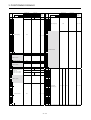
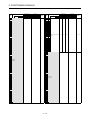
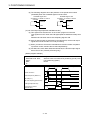
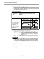
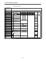
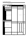
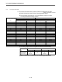
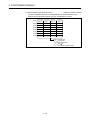
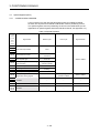
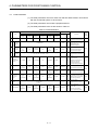
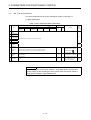
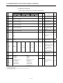
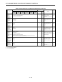
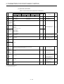
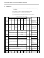
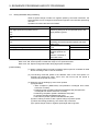
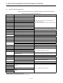
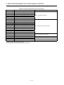
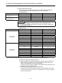
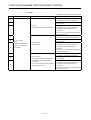
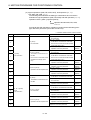
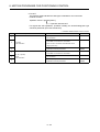
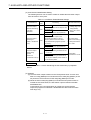
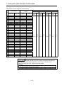
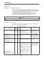
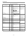
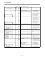
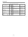
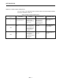
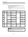
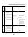
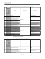
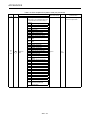
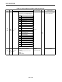
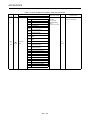
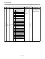
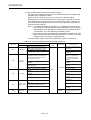
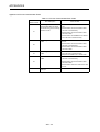
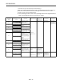
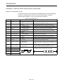
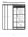
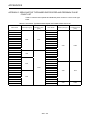
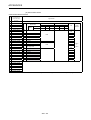
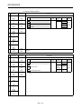
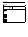
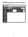
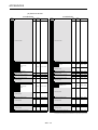
1.1.5
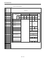
System configuration precautions
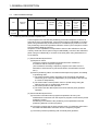
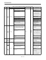
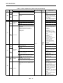
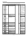
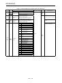
The following table summarizes the notes on system configuration, system setup
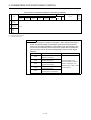
items, and relative checks that differ from those of the A171SCPU.
Product
Name
Separated
amplifier
Module
Name
MR-J2-B
MR-H-B
MR-J-B
Manual pulse
generator
/synchronous A172SENC
encoder
interface
module
A171SENC
Man/machine
control
A271DVP
module
Number of
Available
Modules
1. MR-J2-B allows the use of the following
motors with high-resolution encoders.
• HC-MF***W1 (32768PLS)
• HA-FF***W1 (32768PLS)
• HC-SF**2W2 (131072PLS)
2. [Allowable travel value during power-off]
• Max. 8 axes for
When ABS motor is used, set the
A172SHCPUN
allowable travel value during servo
• Max. 4 axes for
amplifier power-off by rpm (rotations per
A171SHCPUN
minute).
This setting value is used for checking
when the servo amplifier is switched ON.
1
Setting range
Default value
0 to 16383 (rpm)
10 (rpm)
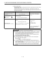
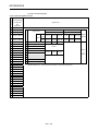
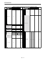
1. External signals
(1) Set the axis numbers which use
external signals FLS, RLS, STOP, and
DOG/CHANGE for A172SENC CTRL
connector signals PX0 to PX1F.
The axes which do not use external
signals may be left unspecified.
CPU unit
Setting range
Default value
A172SHCPUN
Set axes 1 to 8 for
PX0 to PX1F.
Axes 1 to 8
are set.
A171SHCPUN
Set axes 1 to 4 for
the first half (PX0
to PX0F).
Axes 1 to 4
are set.
0
Settings cannot be made.
0
Not available. Settings cannot be made.
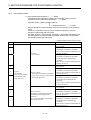
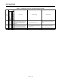
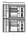
PC CPU I/O A1SX**
A1SY**
module
(motion slot) A1SH42
Up to 256 I/O
points (total)
A1S68B
A1S65B
Up to 1 stage
A168B
Up to 3 stages
PC
extension
base unit
Relative
Check
System Setup Item
Notes and Remarks
• Connect the servo
amplifier to the
'SSCNET1'
interface.
• The setting range
changes for highresolution encoder
support.
• The external signal
• The same
setup window has
axis
been improved for
number
a better
must not be
understanding.
set.
• The conventional
A171SENC can
also be used for
A171SHCPUN and
A172SHCPUN.
However, it must
be set as
A172SENC during
system setting.
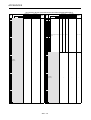
• Though settings
• The total
1. Set the number of points and the starting
can be made within
number of
I/O number for PC CPU I/O modules to be
a range of X/Y0 to
points must
mounted on the motion extension base
X/Y7FF, they must
be less than
unit.
be made in the
or equal to
The number to be set must not precede
range defined in the
256.
the I/O numbers for use by the PC
left-hand column.
• The starting
extension base unit.
I/O number
plus number
Effective
of occupied
CPU unit
Default value
setting range
points must
X/Y0∼X/Y3FF
A172SHCPUN
be less than
or equal to
X/Y0∼X/Y1FF
A171SHCPUN
X/Y800.
• Use this unit for
systems capable of
one-stage extension.
• Use this base in a
system having two
or more extension
bases.
1−7
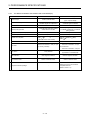
1. GENERAL DESCRIPTION
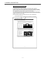
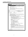
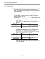
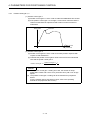
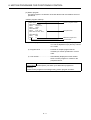
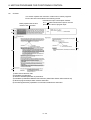
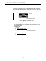
POINT
1. When using the existing A171SCPU user program and parameters,
perform the following procedure:
(1) Start the peripheral S/W package by A172SHCPUN or A171SHCPUN,
then read the sequence file and servo file created for A171SCPU via
the File Read function.
(2) Display the System Setup screen.
The existing system status is displayed with the following alert:
(Start by A172SHCPUN)
Replaces A171SCPU with A172SHCPUN.
Replaces A171SENC with A172SENC.
YES
The character string "A171SHCPUN" is
displayed only when A171SHCPUN is
used for startup.
This message is displayed only when
A171SENC has been set.
NO
(3) Select “YES” and the existing settings will be replaced with those for
the startup CPU module.
Select “NO” and the existing A171SCPU settings will remain in effect.
(4) Utilization of motion program
(a) The handling of the variable type changes.
When a variable has no representation of the type, it is handled as
a 32-bit integer type in the A171SCPU.
A variable is handled as a 16-bit integer type in the
A172SHCPUN/ A171SHCPUN.
"L" or ":L" is added when a variable is handled as a 32-bit integer
type in the A172SHCPUN/A171SHCPUN.
Example:
1) For A171SCPU
#0 ..... [D1,D0] 32-bit integer type
2) For A172SHCPUN/A171SHCPUN
#0 ..... [D0] 16-bit integer type
When handled as 32-bit integer type
#0:L ..... [D1,D0]
For more information, refer to "6.6 Method for Setting the
Positioning Data".
(b) Add a return code to the last line of a program.
The GSV43P edit screen changes.
Before utilizing the program created on SW2SRX-GSV43 Ver.
F/SW2NX-GSV43P Ver. B or earlier, add a return code to the last
line of the program.
After utilization, make an error check for each program number.
The program may not be displayed properly in the presence of an
error.
* Other than system setup data and motion program data can be used
without change.
1−8
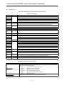
1. GENERAL DESCRIPTION
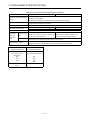
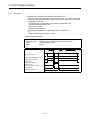
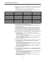
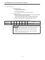
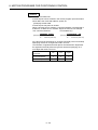
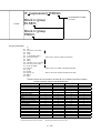
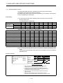
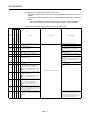
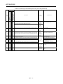
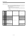
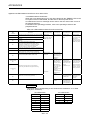
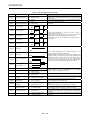
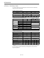
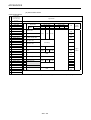
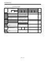
1.2
Table of Software Package
Peripheral software package
Use
Peripheral
devices
For machine
tool
peripheral
DOS/V
1.3
Model name
English
Applicable
Version
SW2SRX-GSV43PE From 00A on
Unit OS software package model name
For
A172SH
CPUN
For
A171SH
CPUN
For
A273UH
CPU
(32 axis
feature)
For
A173UH
CPU
SW0SRXSV43C
SW0SRXSV43F
SW2SRXSV43U
SW2SRXSV43A
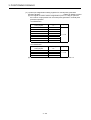
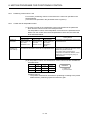
Positioning Control by the Servo System CPU
A servo system CPU can execute positioning control and sequence control for 8
axes (when using A172SHCPUN), 4 axes (when using A171SHCPUN) or 32 axes
(when using A273UHCPU (32 axis feature) or A173UHCPU) by means of a multiaxis positioning control CPU (hereafter called the "PCPU") and a sequence control
CPU (hereafter called the "SCPU").
Sequence control capabilities are equivalent to those of the A2SHCPU's I/O and
memory enhanced version (when using A172SHCPUN), to those of the A2SHCPU
(when using A171SHCPUN), or to those of the A3U (when using A273UHCPU or
A173UHCPU).
(1) Control handled by the SCPU
(a) Sequence control
The SCPU controls I/O modules and special function modules in
accordance with the sequence program.
(The method for executing a sequence program is the same as in the
A2SHCPU's I/O and memory enhanced version, the A2SHCPU and the
A3U.)
(b) Start of positioning start in accordance with sequence program, and setting
of positioning data
1) The SCPU requests motion programs to be executed by the DSFRP
instruction (up to 3 axes for interpolation) or by the SVST instruction (up
to 4 axes for interpolation).
2) The SCPU make a home position return or speed change using the
DSFLP instruction or CHGA/CHGV instruction.
3) The SCPU performs JOG operation.
4) The SCPU sets the data required to execute manual pulse generator
operation.
(2) Control handled by the PCPU
(a) The PCPU executes motion programs requested to be run by the
DSFRP/SVST instruction from the sequence program to exercise the preset
positioning control.
Positioning control data are the positioning control parameters and the
positioning data set in motion programs.
(b) The PCPU changes the set home position return or positioning speed set in
the DSFLP/CHGA/CHGV instruction from the sequence program.
(c) The PCPU performs positioning with a manual pulse generator.
1−9
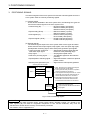
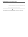
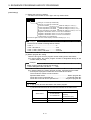
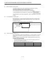
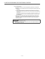
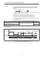
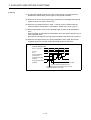
1. GENERAL DESCRIPTION
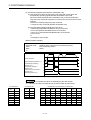
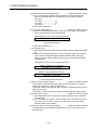
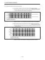
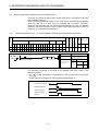
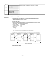
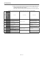
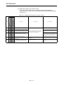
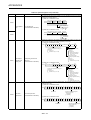
[Executing Positioning Control with a Servo System CPU]
The servo system CPU executes positioning control in accordance with the motion
programs designated by the sequence program of the SCPU.
An overview of the method used for positioning control is presented below.
Servo System CPU System
SCPU Control
using a
.............. Created and modified
1
Sequence program
peripheral device*
Example: DSFRP instruction (A273UHCPU (32 axIs feature) and
A173UHCPU: unusable
"Execution positioning" command
Interlock condition for axis 1
M2001
DSFRP
D1
K15
Motion program No.15
Axis 1 (Controlled axis No.)
Motion program start request
Example: SVST instruction
Request for
execution of
motion program
"Execution positioning" command
Interlock condition for axis 1
M2001
SVST
J1
K15
Motion program No.15
Axis 1 (Controlled axis No.)
Motion program start request
1) In the sequence program, the motion program number and
controlled axis number are set with the DSFRP/SVST instruction.
2) When the DSFRP/SVST instruction is executed, the PCPU is
requested to execute the program with the designated servo
program number.
(1) Motion programs and positioning control parameters are set using a peripheral
device.
(2) Positioning is started by the sequence program (DSFRP/SVST instruction).
(a) The motion program number and controlled axis number are designated by
the DSFRP/SVST instruction.
1) The motion program number can be set either directly or indirectly.
2) The controlled axis number can only be set directly.
1 − 10
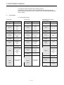
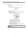
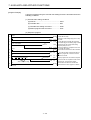
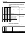
1. GENERAL DESCRIPTION
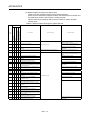
(3) The positioning specified by the designated motion program is executed.
PCPU Control
Motion program
...............
Created and modified using a
1
peripheral device*
Motion program No.
(Program No. allowing program
designation with the SVST
instrctuin)
0015;
N10 G91 G00;
G28 X0. Y0.;
X250.;
N20 M20;
X-50. Y120.;
N30 G01 X25. F500.;
G-coded motion program
(Refer to section 6.1.)
N80 M21;
M02;
%
Program end instruction
which must be set
Positioning control
parameters
Set and changed using a peripheral
device *1
System settings
System data such as axis allocations
Fixed parameters
Home position return data
Fixed data decided, for example, by
the mechanical system
Data decided by the specifications of the
connected servo equipment
Data required to execute acceleration,
deceleration, etc. in positioning control
Data required to execute home position retrun
JOG operation data
Data required for JOG operation
Limit switch output data
ON/OFF pattern data required to execute the
limit switch output function
Work coordinate setting
Data used to set the work coordinate system
Servo parameters
Parameters block
Servo
amplifier
Servo motor
REMARK
*1: Any of the following peripheral devices, running the GSV43P software, can
be used.
• An IBM PC/AT or 100% compatible machine in which PC-DOS 5.0 or a
later version has been installed (hereafter called an “IBM PC”)
IBM is a registered trade mark of International Business
Machines Corporation
1 − 11
1. GENERAL DESCRIPTION
[Executing JOG Operation with a Servo System CPU]
The servo system CPU can be used to perform JOG operation on a designated
axis in accordance with a sequence program.
An overview of JOG operation is presented below.
Servo System CPU System
SCPU Control
Sequence program
.......
Created and modified using a
peripheral device*1
JOG speed setting command
Interlock signal for axis 1
M2001
DMOVP K1000 D964
JOG speed setting
SET M10
Setting of "JOG speed setting
completed flag"
M1802
Switches the forward JOG
execution command (M1802)
ON/OFF
Forward JOG execution command
M10
M1803
Reverse JOG execution
command (for interlock)
Request for
execution of JOG
operation
In the sequence program, after setting the JOG speed, turn the
JOG operation execution flag (M1802/M1803) ON.
(1) Set the positioning control parameters using a peripheral device.
(2) Using the sequence program, set the JOG speed in the JOG operation speed
setting register for each axis.
(3) JOG operation is executed while the JOG operation execution flag is kept ON
by the sequence program.
1 − 12
1. GENERAL DESCRIPTION
PCPU Control
Positioning control
parameters
Set and changed using a peripheral
device *1
System settings
System data such as axis allocations
Fixed parameters
Home position return data
Fixed data decided, for example, by
the mechanical system
Data decided by the specifications of the
connected servo equipment
Data required to execute acceleration,
deceleration, etc. in positioning control
Data required to execute home position retrun
JOG operation data
Data required for JOG operation
Limit switch output data
ON/OFF pattern data required to execute the
limit switch output function
Work coordinate setting
Data used to set the work coordinate system
Servo parameters
Parameters block
Servo
amplifier
Servo motor
REMARK
*1: Any of the following peripheral devices, running the GSV43P software, can
be used.
• IBM PC
1 − 13
1. GENERAL DESCRIPTION
[Executing Manual Pulse Generator Operation with a Servo System CPU]
When executing positioning control with a manual pulse generator connected to an
A172SENC or A171SENC, manual pulse generator operation must be enabled by
the sequence program.
An overview of positioning control using manual pulse generator operation is
presented below.
Servo System CPU System
SCPU Control
Sequence program
MOVP K1 D1012
Operated axis
Input manual pulse generator used
MOVP K100 D1016
SET M2012
Setting for controlling axis 1 with
manual pulse generator P1
1 pulse input magnification
setting is 100
Manual pulse generator used
Operated axis number
1 pulse input magnification
Manual pulse generator
enable
Setting of axis 1 manual pulse
generator operation enable flag
Resetting of axis 1 manual pulse generator
operation enable flag
RST M2012
Manual pulse generator operation
completed flag
Use the sequence program to turn the manual pulse generator
operation enable flag ON after setting the manual pulse generator
used, operation number, and magnification for 1 pulse input.
(1) Set the manual pulse generator used, operated axis number, and magnification
for 1 pulse input by using the sequence program.
(2) Turn the manual pulse generator operation enable flag ON by using the
sequence program.
........................................... manual pulse generator operation enabled
(3) Perform positioning by operating the manual pulse generator.
(4) Turn the manual pulse generator operation enable flag OFF by using the
sequence program.
....................................... manual pulse generator operation completed
1 − 14
1. GENERAL DESCRIPTION
Servo
amplifier
PCPU
Servo motor
Manual pulse
generator
1 − 15
1. GENERAL DESCRIPTION
(1) Positioning control parameters
The positioning control parameters are classified into the eight types shown
below.
Parameter data can be set and corrected interactively by using a peripheral
device.
Item
1 System settings
Description
Reference
The system settings set the modules used, axis numbers, etc.
Section 4.1
Fixed parameters are set for each axis. Their settings are
2 Fixed parameters predetermined by the mechanical system. They are used for
servo motor control during positioning control.
Section 4.2
3
Servo
parameters
Servo parameters are set for each axis. Their settings are
predetermined by the type of servomotor connected. They are
set to control the servomotors during positioning control.
Section 4.3
4
Home position
return data
Home position return data is set for each axis. The return
direction, return method, return speed, etc. are set for home
position return.
Section 4.4
5 JOG operation
JOG operation data is set for each axis. The speed limit value
and parameter block number are set for JOG operation.
Section 4.5
6 Parameter block
Up to 16 parameter blocks are set for acceleration,
deceleration, speed control, etc. during positioning control.
They are designated by the servo program, JOG operation
data, and home position return data to easily change
acceleration and deceleration (acceleration time, deceleration
time, and speed limit value) during positioning control.
Section 4.6
Limit switch
output data
Limit switch output data (ON/OFF pattern data) is set for each
axis to be used when "USE" is set for the limit switch output
setting in the fixed parameter. When positioning control takes
place on an axis for which limit switch output data has been
set, the set ON/OFF pattern of the axis is output to an external
destination.
Section 7.1
Work coordinate
data
Data used to set the work coordinate system. 6 different work
coordinates can be set per axis.
1) G54 Work coordinate system 1
2) G55 Work coordinate system 2
3) G56 Work coordinate system 3
4) G57 Work coordinate system 4
5) G58 Work coordinate system 5
6) G59 Work coordinate system 6
Section 4.7
7
8
1 − 16
1. GENERAL DESCRIPTION
(2) Motion program
A motion program is designed to exercise positioning control and is requested
to be started by the sequence program.
It comprises a motion program number, G code and positioning data.
For details, see Chapter 6.
• Motion program No. ....... This number is designated in the sequence program.
• G code ........................... Indicates the type of positioning control.
• Positioning data ............. Needed to execute the G code. Required data is
predetermined for each G code.
(3) Sequence program
The sequence program serves to enable the execution of positioning control by
motion programs, JOG operation, and manual pulse generator operation.
For details, see Chapter 5.
1 − 17
2. PERFORMANCE SPECIFICATIONS
2. PERFORMANCE SPECIFICATIONS
2.1
SCPU Performance Specifications
Table 2.1.1 and 2.1.2 give the performance specifications of the SCPU.
Table 2.1.1 SCPU Performance Specifications (A172SHCPUN/A171SHCPUN)
Item
A172SHCPUN
Control method
I/O control method
Refresh method/direct method (selectable)
Sequence control dedicated language
(Relay symbol language, logic symbol language, MELSAP II (SFC))
Programming language
Number of instructions
A171SHCPUN
Stored program repeated operation
Sequence instructions
26
Basic instructions
131
Applied instructions
102
Special dedicated instructions
12
Motion dedicated instructions
Processing speed (µs)
(Sequence instruction)
6
0.25 to 1.9 µs/step
Direct method
0.25 µs/step
Refresh method
Number of I/O points
2048 (X/Y0 to X/Y7FF)
Number of real I/O points
1024 (X/Y0 to X/Y3FF)
Watchdog timer (WDT)
10 to 2000ms
Memory size (internal RAM)
Main sequence program
Program capacity
512 (X/Y0 to X/Y1FF)
192 kbytes
64 kbytes
Max. 30 k steps
Max. 14 k steps
Sub-sequence program
None
None
Micro computer program
Max. 58 kbytes
Max. 26 kbytes
1000 (M0 to M999)
Total 2048 points common to
M, L, S
(set with parameters)
No. of internal relays (M) (*1)
No. of latch relays (L)
1048 points (M1000 to M2047)
No. of step relays (S)
0 point (none at initial status)
No. of link relays (B)
1024 points (B0 to B3FF)
Points
Timers (T)
256 points
Time setting
Device
100 ms timer
0.1 to 3276.7s
T0 to T199
10 ms timer
0.01 to 327.67s
T200 to T255
100 ms elapsed time indicator
0.1 to 3276.7s
none at initial
status
Specifications
Set with parameters
256 points
Device
Points
Counters (C)
Setting range
Device
Normal counter
1 to 32767
C0 to C255
Interrupt program counter
1 to 32767
none at initial
status
Specifications
Set with parameters
No. of data registers (D) (*1)
1024 points (D0 to D1023)
No. of link registers (W)
1024 points (W0 to W3FF)
No. of annunciators (F)
256 points (F0 to F255)
No. of file registers (R)
Max. 8192 points (R0 to R8191) (set with parameters)
No. of accumulators (A)
2 points (A0, A1)
No. of index registers (V, Z)
2 points (V, Z)
No. of pointers (P)
256 points (P0 to P255)
No. of interrupt pointers (I)
32 points (I0 to I31)
No. of special-function relays (M)
256 points (M9000 to M9255)
2−1
2. PERFORMANCE SPECIFICATIONS
Table 2.1.1 SCPU Performance Specifications (Continued)
Item
A172SHCPUN
No. of special-function registers (D)
No. of expansion file register block
A171SHCPUN
256 points (D9000 to D9255)
Max. 10 blocks
(set by memory capacity)
Max. 2 blocks
(set by memory capacity)
No. of comments
Max. 4032 (64 kbytes), 1 point = 16 bytes
(Set in 64-point unit)
Number of expansion comments (*2)
Max. 3968 points (63 kbytes), 1 point = 16 bytes
(Set in 64-point unit)
Self-diagnostic function
Watchdog error monitoring, memory/CPU/input/output/battery, etc. error
detection
Operation mode on error
Select stop/continue
Output mode selection when switching from STOP to
RUN
Select re-output operation status before STOP (default) or output after
operation execution.
Clock function
Year, month, day, hour, minute, day of the week (leap year automatic
distinction)
Program/parameter storage in ROM
Not possible
(*1) Range of positioning dedicated devices differs depending on the OS. For details, see Chapter 3.
(*2) The expansion comments are not stored in the internal memory of the CPU.
2−2
2. PERFORMANCE SPECIFICATIONS
Table 2.1.2 SCPU Performance Specifications (A273UHCPU/A173UHCPU(S1))
Item
A273UHCPU
Control method
I/O control method
Programming language
Sequence instructions
Basic instructions
Number of instructions
Applied instructions
Special dedicated instructions
Motion dedicated instructions
Processing speed (µs) (Sequence instruction)
Number of I/O points
Number of real I/O points
Watchdog timer (WDT)
Memory size (internal RAM)
Program capacity
Main sequence program
Sub-sequence program
No. of internal relays (M) (*1)
No. of latch relays (L)
No. of step relays (S)
No. of link relays (B)
Points
Device
Timers (T)
Specifications
Specifications
A173UHCPU-S1
Stored program repeated operation
Refresh method (partial direct I/O enabled by instruction)
Sequence control dedicated language
(Relay symbol language, logic symbol language, MELSAP II (SFC))
22
252
252
204
4
0.15 µs/step
8192 (X/Y0 to X/Y1FFF)
2048 (X/Y0 to X/Y7FF)
2048 (X/Y0 to X/Y7FF)
(Within the range of 1 expansion base unit)
200ms
For loaded memory
cassette capacity
256 kbytes
1024kbytes
(Max. 1024kbytes)
Max. 30 k steps
Max. 30 k steps
8191
(M0 to M999,
M2048 to M8191)
Total 8191 points common to
M, L, S
1048 points (M1000 to
(set with parameters)
M2047)
0 point (none at initial
status)
8192 points (B0 to B1FFF)
2048 points (Initial status: 256 points)
Time setting
Device
100 ms timer
10 ms timer
0.1 to 3276.7s
0.01 to 327.67s
100 ms elapsed time indicator
0.1 to 3276.7s
T0 to T199
T200 to T255
none at initial
status
Extended timer
Time set by word
device (D, W, R)
T256 to T2047
Set with parameters
1024 points (Initial status: 256 points)
Points
Counters (C)
A173UHCPU
Setting range
Device
Normal counter
1 to 32767
Interrupt program counter
C244 to 255
C0 to C255
none at initial
status
Extended counter
Count value set
by word device
(D, W, R)
C256 to C1023
Set with parameters
8192 points (D0 to D8191)
8192 points (W0 to W1FFF)
2048 points (F0 to F2047)
Max. 8192 points (R0 to R8191) (set with parameters)
2 points (A0, A1)
14 points (V, V1 to V6, Z, Z1 to Z6)
256 points (P0 to P255)
32 points (I0 to I31)
256 points (M9000 to M9255)
No. of data registers (D) (*1)
No. of link registers (W)
No. of annunciators (F)
No. of file registers (R)
No. of accumulators (A)
No. of index registers (V, Z)
No. of pointers (P)
No. of interrupt pointers (I)
No. of special-function relays (M)
2−3
2. PERFORMANCE SPECIFICATIONS
Table 2.1.2 SCPU Performance Specifications (Continued)
Item
A273UHCPU
A173UHCPU
No. of special-function registers (D)
No. of expansion file register block
A173UHCPU-S1
256 points (D9000 to D9255)
Max. 46 blocks
(set by memory
cassette or memory
capacity)
Max. 2 blocks
(set by memory
capacity)
Max. 46 blocks
(set by memory
capacity)
No. of comments
Max. 4032 (64 kbytes), 1 point = 16 bytes
(Set in 64-point unit)
Number of expansion comments (*2)
Max. 3968 points (63 kbytes), 1 point = 16 bytes
(Set in 64-point unit)
Self-diagnostic function
Watchdog error
monitoring,
Watchdog error monitoring
memory/CPU/input/out
(watchdog timer fixed to 200msec)
put/battery, etc. error
detection
Operation mode on error
Select stop/continue
Output mode selection when switching from STOP to
RUN
Select re-output operation status before STOP (default) or output after
operation execution.
Clock function (*3)
Year, month, day, hour, minute, day of the week (leap year automatic
distinction)
Program/parameter storage in ROM
Not possible
RUN-time start method
Initial start
Latch (power failure compensation) range
L1000 to L2047 (default) (latch ranges can be set for L, B, T, C, D and
W)
Remote RUN and PAUSE contacts
From among X0 to X1FFF, one point can each be set as the RUN and
PAUSE contacts.
I/O assignment
The number of I/O points occupied and module type can be registered.
Step run
Sequence program operation can be executed and stopped.
Interrupt processing
Interrupt or cyclic interrupt signal can be used to run interrupt program.
Data link
MELSECNET/10, MELSECNET(II)
(*1) Range of positioning dedicated devices differs depending on the OS. For details, see Chapter 3.
(*2) The expansion comments are not stored in the internal memory of the CPU.
(*3) The year data read by the clock element is only the lower two digits of the year.
When used in sequence control, the year data must be compensated for by the sequence program in some applications of using the data.
2−4
2. PERFORMANCE SPECIFICATIONS
2.2
PCPU Performance Specifications
Table 2.2.1 and 2.2.2 give the performance specifications of the PCPU.
Table 2.2.1 PCPU Performance Specifications (A172SHCPUN/A171SHCPUN)
Item
Number of control axes
A172SHCPUN
A171SHCPUN
8 axes (simultaneous: 2 to 4 axes,
independent: 8 axes)
Interpolation functions
4 axes (simultaneous: 2 to 4 axes,
independent: 4 axes)
Linear interpolation (4 axes max.), circular interpolation (2 axes)
Control modes
PTP(point to point), constant speed control, high-speed oscillation control
mm ! inch ! degree
Control units
Programming language
Motion
program
Dedicated instructions (NC language (EIA))
Capacity
Number of points
for positioning
Program setting method
59kbytes
Approx. 2700 points/axis
(These values vary depending on the programs. Positioning data can be designated indirectly.)
Setting with an IBM PC, running the GSV43P software
Number of simultaneously
startable programs
Method
8 programs
PTP
: Selection of absolute data method or
incremental method
Constant speed control
: The absolute method and incremental method
can be used together
High-speed oscillation control
: Absolute data method
Commands can be selected for each axis.
Control Unit
Positioning
Position
commands
mm
× 10−4 mm
inch
× 10−5 inch
degree
Control Unit
Speed command
(command unit)
Acceleration/
deceleration
control
Automatic
trapezoidal
acceleration/
deceleration
S curve
acceleration/
deceleration
Backlash
Compensation compensation
Electronic gear
Home position return function
Command Unit
−5
× 10
Address Setting Range
−2147483648 to 2147483647
degree
Travel Value Setting
Range
0 to ±2147483647
0 to 35999999
Speed Setting range
mm
0.01 to 6000000.00
(mm/min)
inch
0.001 to 600000.000
(inch/min)
degree
0.001 to 2147483.647
(degree/min)
(*1)
Acceleration-fixed acceleration/deceleration
Time-fixed acceleration/deceleration
Acceleration time: 1 to 65535ms
Deceleration time: 1 to 65535ms
Acceleration/deceleration time: 1 to 5000ms
(Only constant speed control is possible.)
S curve ratio setting: 0 to 100%
(0 to 65535) × position command unit (units converted to pulses: 0 to 65535 pulses)
Compensation function for error in actual travel value with respect to command value
When an absolute position system is not used : Selection of near-zero point dog type or count
type
When an absolute position system is used
: Selection of data set type, near-zero point dog
type or count type
JOG operation function
Provided
2−5
2. PERFORMANCE SPECIFICATIONS
Table 2.2.1 PCPU Performance Specifications (Continued)
Item
A172SHCPUN
A171SHCPUN
A maximum of one manual pulse generator can be connected.
Manual pulse generator operation
A maximum of three manual pulse generators can be operated.
function
Setting of magnification: 1 to 10000. It is possible to set the smoothing magnification.
M code output function provided
M code completion wait function provided
M function
Skip function
Provided
Limit switch output function
Number of output points
8 point/axis
Number of ON/OFF setting points
10 points/axis
Override ratio setting function
High-speed
reading of
designated
data
Override ratio setting: 0 to 100%
Number of input
points
Max. 9 points
(TREN input of A172SENC (1 point) + one motion slot PC input module (8 points))
Data latch timing
At leading edge of the TREN input signal
Within 0.8ms of the signal leading edge for the PC input module
Absolute position system
Possible with a motor equipped with an absolute position detector.
(Possible to select the absolute data method or incremental method for each axis)
(*1) Acceleration-fixed acceleration/deceleration and time-fixed acceleration/deceleration are switched over as indicated below.
Acceleration-fixed
acceleration/deceleration
Time-fixed
acceleration/deceleration
During G100
G00 (without M code
designation)
G28
G30
G53
During G100
G00 (with M code designation)
All move commands during
G101
G01
G02
G03
G32
-
2−6
2. PERFORMANCE SPECIFICATIONS
Table 2.2.2 PCPU Performance Specifications (A273UHCPU/A173UHCPU(S1))
Item
Number of control axes
A273UHCPU (32 axis feature)
Interpolation functions
Linear interpolation (4 axes max.), circular interpolation (2 axes)
Control modes
PTP(point to point), constant speed control, high-speed oscillation control
mm ! inch ! degree
Control units
Programming language
Motion
program
A173UHCPU(S1)
32 axes (simultaneous: 2 to 8 axes, independent: 32 axes)
Dedicated instructions (NC language (EIA))
Capacity
Number of points
for positioning
Program setting method
126kbytes
Approx. 5400 points/axis
(These values vary depending on the programs. Positioning data can be designated indirectly.)
Setting with an IBM PC, running the GSV43P software
Number of simultaneously
startable programs
Method
8 programs
PTP
: Selection of absolute data method or
incremental method
Constant speed control
: The absolute method and incremental method
can be used together
High-speed oscillation control
: Absolute data method
Commands can be selected for each axis.
Control Unit
Positioning
Position
commands
mm
× 10−4 mm
inch
× 10−5 inch
degree
Control Unit
Speed command
(command unit)
Acceleration/
deceleration
control
Automatic
trapezoidal
acceleration/
deceleration
S curve
acceleration/
deceleration
Backlash
Compensation compensation
Electronic gear
Home position return function
Command Unit
mm
Address Setting Range
−2147483648 to 2147483647
× 10−5 degree
Travel Value Setting
Range
0 to ±2147483647
0 to 35999999
Speed Setting range
0.01 to 6000000.00
(mm/min)
inch
0.001 to 600000.000
(inch/min)
degree
0.001 to 2147483.647
(degree/min)
(*1)
Acceleration-fixed acceleration/deceleration
Time-fixed acceleration/deceleration
Acceleration time: 1 to 65535ms
Deceleration time: 1 to 65535ms
Acceleration/deceleration time: 1 to 5000ms
(Only constant speed control is possible.)
S curve ratio setting: 0 to 100%
(0 to 65535) × position command unit (units converted to pulses: 0 to 65535 pulses)
Compensation function for error in actual travel value with respect to command value
When an absolute position system is not used : Selection of near-zero point dog type or count
type
When an absolute position system is used
: Selection of data set type, near-zero point dog
type or count type
JOG operation function
Provided
2−7
2. PERFORMANCE SPECIFICATIONS
Table 2.2.2 PCPU Performance Specifications (Continued)
Item
A273UHCPU (32 axis feature)
A173UHCPU(S1)
Up to 3 manual pulse generators are connectable. Up to 3 axes can be operated simultaneously
Manual pulse generator operation
per manual pulse generator.
function
Input magnification setting: 1 to 10000, with smoothing magnification setting
M code output function provided
M code completion wait function provided
M function
Skip function
Provided
Limit switch output function
Number of output points
8 point/axis
Number of ON/OFF setting points
10 points/axis
Override ratio setting function
High-speed
reading of
designated
data
Override ratio setting: 0 to 100%
Number of input
points
Max. 9 points
Max. 11 points
(TREN input of A273EX (3 points) + one motion (TREN input of A172SENC (1 point) + one
motion slot PC input module (8 points))
slot PC input module (8 points))
Data latch timing
At leading edge of the TREN input signal
Within 0.8ms of the signal leading edge for the PC input module
Absolute position system
Possible with a motor equipped with an absolute position detector.
(Possible to select the absolute data method or incremental method for each axis)
(*1) Acceleration-fixed acceleration/deceleration and time-fixed acceleration/deceleration are switched over as indicated below.
Acceleration-fixed
acceleration/deceleration
Time-fixed
acceleration/deceleration
During G100
G00 (without M code
designation)
G28
G30
G53
During G100
G00 (with M code designation)
All move commands during
G101
G01
G02
G03
G32
-
2−8
2. PERFORMANCE SPECIFICATIONS
2.3
The Differences between A172SHCPUN/A171SHCPUN and A171S(S3) and the Differences between
A273UHCPU (32 axis feature) and A173UHCPU(S1)
2.3.1
The differences between A172SHCPUN/A171SHCPUN and A171S(S3)
Motion
Item
Number of control axes
Computing frequency
Sequencer CPU
Processing speed (µs)
(Sequence instruction)
A172SHCPUN
A171SHCPUN
8 axes
4 axes
3.5ms/1 to 8 axes
3.5ms/1 to 4 axes
Equivalent to reinforced
I/O memory of
A2SHCPU
Equivalent to A2SHCPU
Direct method
PC
Program capacity (main sequence)
MELSECNET/J
System configuration
No. of SSCNET I/F
1.0 µs/step
512 points
256 points
192 kbytes (Equivalent to
A3NMCA24)
64 kbytes (Equivalent to
A3NMCA8)
32 kbytes
Max. 30 k step
Max. 14 k step
Max. 8 k step
Max. 8192 points
Max. 10 blocks
Max. 4096 points
Max. 3 blocks
" (Supported by special commands)
None
" (By means of
FROM/TO commands)
Max. three (*2)
Max. one
A172SENC
(Corresponding to external signal input 8-axes)
A171SENC
(Corresponding to external signal input 4-axes)
2CH.
SSCNET1 ......... For connection of servo amplifier
SSCNET2 ......... For personal computer link
dedicated
Unavailable
A171S
: 1CH.
A171S-S3 : 2CH.
(as given to the left)
Max. two
Compatibility
After starting A172SH/A171SH and reading a file,
those created by A171SCPU can be used as it is.
Parameter
Additional functions
Motion program
−
1024 points
No. of available A271DVP
Sequence program, parameter
Equivalent to A1SCPU
0.25 µs/step
Number of PC extension base unit
Pulser synchronous encoder interface unit
7.1 ms/4 axes
2048 points
No. of file register (R)
No. of expansion file register blocks (*1)
SV43
1.0 to 2.3 µs/step
Refresh method
Memory capacity (built-in RAM)
4 axes
3.5 ms/1 to 3 axes
0.25 to 1.9 µs/step
No. of I/O
No. of actual I/O
A171SCPU(S3)
• Support of high-resolution encoder
(32768PLS/131072PLS)
"
×
• A torque limit value can be changed from a
sequence program (CHGT instruction
addition).
"
×
• Retracing during positioning
"
×
System setting
By making sure of system setting screen after being
started up by A172SH/A171SH and reading a file,
changeover below is carried out: now the system is
ready for operation.
A171SCPU → A172SH/A171SHCPUN
A171SENC → A172SENC
(*1) No. of expansion file register blocks varies depending on the setting of program capacity, No. of file registers, and No. of comments.
(*2) Up to one extension base for the MELSEC PC A2SHCPU-S1/A2SHCPU.
2−9
2. PERFORMANCE SPECIFICATIONS
2.3.2
The differences between A273UHCPU and A173UHCPU(S1)
Item
A273UHCPU
A173UHCPU(S1)
A278LX, A273EX used
A172SENC used
(up to 4 inputs usable)
DOG/CHANGE signal
Near-zero point DOG signal and
CHANGE signal are independent
Near-zero point DOG signal and
CHANGE signal are shared
Synchronous encoder
12 encoders usable
4 encoders usable
3 manual pulse generators usable:
usable with one A273EX
3 manual pulse generators usable: one
A172SENC needed per one manual
pulse generator
3 points
1 point
12 points
4 points
External input
Motion control
Manual pulse generator
High-speed read (TREN input)
External input clutch
Usable servo amplifier
B/MR-H
B(N)/
• MR-J2MR-J
B
• ADU (AC motor drive module)
Motion extension base
Within 4 extension bases
Others
Sequence control
Cam data
256 lines of resolution × 256 pcs. (set
by memory cassette)
B/MR-H
• MR-J2MR-J
B
B(N)/
None
A173UHCPU
...... 256 lines of resolution × 64 pcs.
A173UHCPU-S1
...... 256 lines of resolution × 256 pcs.
2 key switches
1 key switch
(equivalent to A172SHCPUN)
LED indication
With segment indication
Without segment indication
PC extension base
Within 7 extension bases
Within 1 extension base
Key switch
−
Peripheral software package
2 − 10
Usable from among A173UHCPUcompatible versions
(Refer to section 1.3)
3. POSITIONING SIGNALS
3. POSITIONING SIGNALS
The internal signals of the servo system CPU and the external signals sent to the
servo system CPU are used as positioning signals.
(1) Internal signals
Of the devices available in the servo system CPU, the following four types are
used for the internal signals of the servo system CPU.
• Internal relay (M) .............................. M1400 to M2047 (348 points)
M2000 to M3839 (840 points)
M4000 to M4719 (720 points)
• Special relay (SP.M) ........................ M9073 to M9079 (7 points)
M9073 to M9079 (7 points)
• Data register (D) .............................. D500 to D1023 (524 points)
D0 to D1689 (1690 points)
• Special register (SP.D) .................... D9180 to D9199 (20 points)
D1980 to D9199 (20 points)
(2) External signals
The external signals input to the servo system CPU are the upper and lower
stroke end limit switch input signals, stop signals, near-zero point dog signal,
speed/position switching signal, and manual pulse generator input signals.
• Upper and lower stroke end ............ Signals that control the upper limit and
limit switch input signal
lower limit of the positioning range
• Stop signal ....................................... Stop signal for speed control
• Near-zero point dog signal............... The ON/OFF signal from the near-zero
point dog
• Speed/position switching signal ....... Signal that switches control from speed to
position control
• Manual pulse generator input .......... Signal from the manual pulse generator
Servo System CPU System
SP.D, SP.M, X*1
Y *2
SCPU
PCPU
D *3
M
*4
External
interface
*1: SP.D, SP.M and X are signals that notify the
SCPU of the PCPU control status.
*2: Y are signals that notify the PCPU of position
control commands from the SCPU.
*3: D are registers that notify the PCPU of control
commands from the SCPU and the SCPU of
control status information from the PCPU.
*4: M are flags that notify the PCPU of control
commands from the SCPU and the SCPU
of control status information from the PCPU.
Near-zero point dog signal
Upper limit/lower stroke end limit switch
Stop signal
Manual pulse generator
Fig.3.1 Flow of Positioning Signals
POINT
When the monitor data (machine values, actual present values, deviation counter, etc.) stored in the
data registers (D) are used for magnitude comparison or four function arithmetic, they must be
transferred to another device memory once and then processed.
For transfer, refer to "Appendix-4.5".
3−1
3. POSITIONING SIGNALS
The following section describes the positioning devices.
It indicates the device refresh cycles for signals with the positioning direction
PCPU→SCPU and the device fetch cycles for those with the positioning direction
SCPU→PCPU.
3.1
Internal Relays
(1) List of internal relays
A172SHCPUN
A273UHCPU (32 axis feature)/
A173UHCPU(S1)
A171SHCPUN
Device No.
Purpose
Device No.
Purpose
Device No.
Purpose
M0
User device
(1400 points)
M0
User device
(1400 points)
M0
User device
(2000 points)
M1400
Axis status for
SV43
(10 points × 8
axes)
M1400
Axis status for
SV43
(10 points × 4
axes)
M2000
Common device
(88 points)
M1480
Unusable
(20 points)
M1440
Unusable
(60 points)
M2320
Unusable
(80 points)
M1500
Axis command
signal for SV43
(10 points × 8
axes)
M1500
Axis command
signal for SV43
(10 points × 4
axes)
M2400
Axis status
(20 points × 32
axes)
M1580
Unusable
(20 points)
M1540
Unusable
(60 points)
M3040
Unusable
(160 points)
M1600
Axis status
(20 points × 8
axes)
M1600
Axis status
(20 points × 4
axes)
M3200
M3839
Axis command
signal
(20 points × 32
axes)
M1760
Unusable
(40 points)
M1680
Unusable
(120 points)
M3840
User device
(160 points)
M1800
M1800
Axis command
signal
(20 points × 8
axes)
Axis command
signal
(20 points × 4
axes)
M4000
Axis status for
SV43
(10 points × 32
axes)
M4320
Unusable
(80 points)
M4400
Axis command
signal for SV43
(10 points × 32
axes)
M1960
M2000
M2047
Unusable
(40 points)
M1880
M1960
Common device
(88 points)
M2000
Common device
(88 points)
M2047
M4720
M8191
3−2
User device
(3472 points)
3. POSITIONING SIGNALS
POINTS
• Total Number of User Device Points
A172SHCPUN
1400 points
A171SHCPUN
1400 points
A273UHCPU
(32 axis feature)
5632 points
A173UHCPU(S1)
(1) Internal relays for positioning control are not latched even inside the latch
range.
In this manual, in order to indicate that internal relays for positioning
control are not latched, the expression used in this text is "M1400 to
M1999".
(2) Internal relays for positioning control are monitored from peripheral
devices as shown below.
(a) When peripheral devices are started with GSV43P, positioning
control internal relays within a latch range are indicated by L1400 to
L1999.
3−3
3. POSITIONING SIGNALS
(2) Axis status
• Axis status for SV43
Axis
No.
A172SHCPUN
Device Number
A171SHCPUN
Device Number
1
M1400
to
M1409
M1400
to
M1409
2
M1410
to
M1419
M1410
to
M1419
3
M1420
to
M1429
M1420
to
M1429
4
M1430
to
M1439
M1430
to
M1439
5
M1440
to
M1449
6
M1450
to
M1459
7
M1460
to
M1469
8
M1470
to
M1479
Signal Name
Fetch
Cycle
Signal Name
0
Unusable
1
Unusable
2
Automatically operating
3
Temporarily stopping
4
Unusable
5
Unusable
6
Unusable
7
Unusable
Refresh Cycle
Signal
Direction
−
10ms
−
8
Unusable
9
Single block mode in progress (*1)
SCPU
←
PCPU
3.5ms
(*1) The single block in progress is not an axis status. It is used with the first axis
(M1409) only. The user cannot use it for other than the first axis.
• Axis status
Axis
No.
A172SHCPUN
Device Number
A171SHCPUN
Device Number
1
M1600
to
M1619
M1600
to
M1619
2
M1620
to
M1639
M1620
to
M1639
3
M1640
to
M1659
M1640
to
M1659
4
M1660
to
M1679
M1660
to
M1679
5
M1680
to
M1699
6
M1700
to
M1719
7
M1720
to
M1739
8
M1740
to
M1759
Signal Name
Signal Name
0
Fetch
Cycle
Refresh Cycle
Signal
Direction
Positioning start completed
1
Positioning completed
2
In-position
3
Command in-position
4
Unusable
5
Unusable
6
Zero pass
3.5ms
7
Error detection
8
Servo error detection
3.5ms
9
Home position return request
10ms
3.5ms
10
Home position return completed
11
External signal FLS
12
External signal RLS
13
External signal STOP
14
External signal DOG/CHANGE
Immediately
10ms
15
Servo ON/OFF
16
Torque control in progress
17
(External signal DOG/CHANGE)
10ms
18
19
Unusable
M code output in progress
3.5ms
3−4
3.5ms
SCPU
←
PCPU
3. POSITIONING SIGNALS
Axis No.
• Axis status
A273UHCPU
(32 axis feature)
A173UHCPU
(S1)
Device No.
1
M2400 to M2419
2
M2420 to M2439
3
M2440 to M2459
4
M2460 to M2479
Single name
Signal name
A173
SV43
5
Fetch cycle
Set number of axis
1 to 12
13 to 24 25 to 32
1 to 12
13 to 24 25 to 32
1 to 8
9 to 18
19 to 32
1 to 8
9 to 18
3.5ms
7.1ms
14.2ms
UHCPU
A273
M2480 to M2499
Refresh cycle
Set number of axis
Signal
direction
19 to 32
UHCPU
6
M2500 to M2519
0
7
M2520 to M2539
1
Positioning start completed
Positioning completed
8
M2540 to M2559
2
In-position
9
M2560 to M2579
3
Command in-position
10 M2580 to M2599
4
Unusable
11 M2600 to M2619
5
Unusable
12 M2620 to M2639
6
Zero pass
13 M2640 to M2659
7
Error detection
14 M2660 to M2679
8
Servo error detection
3.5ms
15 M2680 to M2699
9
Home position return request
10ms
16 M2700 to M2719
10 Home position return completed
17 M2720 to M2739
11 External signal FLS
18 M2740 to M2759
12 External signal RLS
19 M2760 to M2779
13 External signal STOP
20 M2780 to M2799
14 External signal DOG
21 M2800 to M2819
15 Servo ON/OFF
22 M2820 to M2839
16 Torque control in progress
23 M2840 to M2859
17 (External signal CHANGE)
24 M2860 to M2879
18 Unusable
25 M2880 to M2899
19 M code output in progress
Immediately
3.5ms
10ms
3.5ms
10ms
3.5ms
26 M2900 to M2919
27 M2920 to M2939
28 M2940 to M2959
29 M2960 to M2979
30 M2980 to M2999
31 M3000 to M3019
32 M3020 to M3039
3−5
7.1ms
14.2ms
20ms
7.1ms
14.2ms
20ms
7.1ms
14.2ms
20ms
7.1ms
14.2ms
SCPU
PCPU
3. POSITIONING SIGNALS
Axis No.
• Axis status for SV43
A273UHCPU
(32 axis feature)
A173UHCPU
(S1)
Device No.
1
M4000 to M4009
2
M4010 to M4019
3
M4020 to M4029
4
M4030 to M4039
Single name
Signal name
A173
SV43
5
Fetch cycle
Set number of axis
1 to 12
13 to 24 25 to 32
1 to 12
13 to 24 25 to 32
1 to 8
9 to 18
1 to 8
9 to 18
UHCPU
A273
M4040 to M4049
Refresh cycle
Set number of axis
19 to 32
Signal
direction
19 to 32
UHCPU
6
M4050 to M4059
0
Unusable
7
M4060 to M4069
1
Unusable
8
M4070 to M4079
2
Automatically operating
9
M4080 to M4089
3
Temporarily stopping
10 M4090 to M4099
4
Unusable
11 M4100 to M4109
5
Unusable
12 M4110 to M4119
6
Unusable
13 M4120 to M4129
7
Unusable
14 M4130 to M4139
8
Unusable
15 M4140 to M4149
9
Single block mode in progress (*1)
16 M4150 to M4159
17 M4160 to M4169
−
10ms
20ms
SCPU
PCPU
−
3.5ms
7.1ms
14.2ms
(*1) The single block in progress is not an axis status. It is used with the first axis (M4009) only. The
user cannot use it for other than the first axis.
18 M4170 to M4179
19 M4180 to M4189
20 M4190 to M4199
21 M4200 to M4209
22 M4210 to M4219
23 M4220 to M4229
24 M4230 to M4239
25 M4240 to M4249
26 M4250 to M4259
27 M4260 to M4269
28 M4270 to M4279
29 M4280 to M4289
30 M4290 to M4299
31 M4300 to M4309
32 M4310 to M4319
3−6
3. POSITIONING SIGNALS
(3) Axis command signals
• Axis command signals for SV43
Axis
No.
A172SHCPUN
Device Number
A171SHCPUN
Device Number
1
M1500
to
M1509
M1500
to
M1509
2
M1510
to
M1519
M1510
to
M1519
3
4
M1520
to
M1529
M1530
to
M1539
5
M1540
to
M1549
6
M1550
to
M1559
7
M1560
to
M1569
8
M1570
to
M1579
M1520
to
M1529
M1530
to
M1539
Signal Name
Fetch
Cycle
Signal Name
0
Temporary stop command
1
Optional program stop
2
Optional block skip
3
Single block
4
Restart
5
Override valid/invalid
6
Unusable
Refresh
Cycle
Signal
Direction
3.5ms
At start
SCPU
7
Unusable
8
Single block mode (*1)
3.5ms
PCPU
−
9 Single block start (*1)
(*1) The single block mode and single block start are not axis statuses. They are used
with the first axis (M1508, M1509) only. The user cannot use them for other than
the first axis.
• Axis command signals
Axis
No.
A172SHCPUN
Device Number
A171SHCPUN
Device Number
1
M1800
to
M1819
M1800
to
M1819
2
M1820
to
M1839
M1820
to
M1839
M1840
to
M1859
M1840
to
M1859
3
4
5
6
7
8
M1860
to
M1879
M1880
to
M1899
M1900
to
M1919
M1920
to
M1939
M1940
to
M1959
M1860
to
M1879
Signal Name
Signal Name
0
Stop command
1
Rapid stop command
2
Forward rotation JOG command
3
Reverse rotation JOG command
4
Completion signal OFF command
Unusable
6
Limit switch output enable
7
Error reset
8
Servo error reset
9
Start-time stop input invalid
10
Unusable
Unusable
12
Unusable
13
Unusable
14
Unusable
15
Servo OFF
16
Unusable
17
Unusable
18
Unusable
19
FIN signal
Refresh
Cycle
Signal
Direction
3.5ms
10ms
−
5
11
Fetch
Cycle
3.5ms
10ms
At start
SCPU
PCPU
−
3.5ms
−
3.5ms
3−7
3. POSITIONING SIGNALS
Axis No.
• Axis command signals
A273UHCPU
(32 axis feature)
A173UHCPU
(S1)
Device No.
1
M3200 to M3219
2
M3220 to M3239
3
M3240 to M3259
4
M3260 to M3279
Single name
Signal name
A173
SV43
5
Fetch cycle
Set number of axis
1 to 12
13 to 24 25 to 32
1 to 12
13 to 24 25 to 32
1 to 8
9 to 18
1 to 8
9 to 18
19 to 32
3.5ms
7.1ms
14.2ms
UHCPU
A273
M3280 to M3299
Refresh cycle
Set number of axis
19 to 32
Signal
direction
UHCPU
6
M3300 to M3319
0
Stop command
7
M3320 to M3339
1
Rapid stop command
8
M3340 to M3359
2
Forward rotation JOG
command
9
M3360 to M3379
3
Reverse rotation JOG
command
10 M3380 to M3399
4
Completion signal OFF
command
11 M3400 to M3419
5
Unusable
12 M3420 to M3439
6
Limit switch output enable
13 M3440 to M3459
7
Error reset
14 M3460 to M3479
8
Servo error reset
15 M3480 to M3499
9
Start-time stop input invalid
16 M3500 to M3519
10 Unusable
17 M3520 to M3539
11 Unusable
18 M3540 to M3559
12
19 M3560 to M3579
13 Unusable
20 M3580 to M3599
14 Unusable
21 M3600 to M3619
15 Servo OFF
10ms
3.5ms
16 Unusable
23 M3640 to M3659
17 Unusable
24 M3660 to M3679
18 Unusable
25 M3680 to M3699
19 FIN signal
7.1ms
10ms
14.2ms
20ms
At start
At start
−
3.5ms
7.1ms
14.2ms
−
3.5ms
26 M3700 to M3719
27 M3720 to M3739
28 M3740 to M3759
29 M3760 to M3779
30 M3780 to M3799
31 M3800 to M3819
32 M3820 to M3839
3−8
7.1ms
SCPU
PCPU
−
Present feed value update
request command
22 M3620 to M3639
20ms
14.2ms
3. POSITIONING SIGNALS
Axis No.
• Axis command signals for SV43
A273UHCPU
(32 axis feature)
A173UHCPU
(S1)
Device No.
1
M4400 to M4409
2
M4410 to M4419
3
M4420 to M4429
4
M4430 to M4439
Single name
Signal name
A173
SV43
5
Fetch cycle
Set number of axis
1 to 12
13 to 24 25 to 32
1 to 12
13 to 24 25 to 32
1 to 8
9 to 18
19 to 32
1 to 8
9 to 18
3.5ms
7.1ms
14.2ms
UHCPU
A273
M4440 to M4449
Refresh cycle
Set number of axis
Signal
direction
19 to 32
UHCPU
6
M4450 to M4459
0
Temporary stop command
7
M4460 to M4469
1
Optional program stop
8
M4470 to M4479
2
Optional block skip
9
M4480 to M4489
3
Single block
10 M4490 to M4499
4
Restart
11 M4500 to M4509
5
Override valid/invalid
12 M4510 to M4519
6
Unusable
13 M4520 to M4529
7
Unusable
14 M4530 to M4539
8
Single block mode (*1)
15 M4540 to M4549
9
Single block start (*1)
16 M4550 to M4559
17 M4560 to M4569
At start
SCPU
3.5ms
7.1ms
14.2ms
PCPU
−
(*1) The single block mode and single block start are not axis statuses. They are used with the first axis
(M4408, M4409) only. The user cannot use them for other than the first axis.
18 M4570 to M4579
19 M4580 to M4589
20 M4590 to M4599
21 M4600 to M4609
22 M4610 to M4619
23 M4620 to M4629
24 M4630 to M4639
25 M4640 to M4649
26 M4650 to M4659
27 M4660 to M4669
28 M4670 to M4679
29 M4680 to M4689
30 M4690 to M4699
31 M4700 to M4709
32 M4710 to M4719
3−9
3. POSITIONING SIGNALS
(4) Common devices
A172SHCPUN
Device
Number
M1960
M1961
M1962
M1963
M1964
M1965
M1966
M1967
M1968
M1969
M1970
M1971
M1972
M1973
M1974
M1975
M1976
M1977
M1978
M1979
M1980
M1981
M1982
M1983
M1984
M1985
M1986
M1987
M1988
M1989
M1990
M1991
M1992
M1993
M1994
M1995
M1996
M1997
M1998
M1999
M2000
M2001
M2002
M2003
M2004
M2005
M2006
M2007
M2008
M2009
M2010
M2011
M2012
M2013
M2014
M2015
M2016
M2017
M2018
M2019
M2020
M2021
M2022
M2023
M2024
M2025
M2026
M2027
M2028
M2029
M2030
M2031
M2032
M2033
M2034
M2035
M2036
M2037
M2038
M2039
M2040
M2041
M2042
M2043
M2044
M2045
M2046
M2047
Signal Name
Unusable (40 points)
PC READY flag
Axis 1
Axis 2
Axis 3
Axis 4
START accept flag
(8 points)
Axis 5
Axis 6
Axis 7
Axis 8
All-axes servo ON accept flag
Unusable (2 points)
Manual pulse generator enable flag
Unusable (2 points)
JOG simultaneous start command
Unusable (4 points)
A172SHCPUN
Fetch
Cycle
Refresh
Cycle
Signal Direction
−
−
−
10ms
10ms
−
−
−
−
System setting error flag
All-axes servo ON command
Unusable (4 points)
Motion slot module error detection flag
−
−
−
−
SCPU→PCPU
−
−
END
SCPU←PCPU
−
−
END
SCPU←PCPU
−
−
END
SCPU←PCPU
SCPU→PCPU
3.5ms
−
SCPU←PCPU
SCPU→PCPU
10ms
PC link communication error flag
Unusable (6 points)
−
10ms
Start buffer full
Axis 1
Axis 2
Axis 3
Axis 4
Speed change flag
(8 points)
Axis 5
Axis 6
Axis 7
Axis 8
Unusable (5 points)
SCPU→PCPU
−
−
END
SCPU←PCPU
Device
Number
M1960
M1961
M1962
M1963
M1964
M1965
M1966
M1967
M1968
M1969
M1970
M1971
M1972
M1973
M1974
M1975
M1976
M1977
M1978
M1979
M1980
M1981
M1982
M1983
M1984
M1985
M1986
M1987
M1988
M1989
M1990
M1991
M1992
M1993
M1994
M1995
M1996
M1997
M1998
M1999
M2000
M2001
M2002
M2003
M2004
M2005
M2006
M2007
M2008
M2009
M2010
M2011
M2012
M2013
M2014
M2015
M2016
M2017
M2018
M2019
M2020
M2021
M2022
M2023
M2024
M2025
M2026
M2027
M2028
M2029
M2030
M2031
M2032
M2033
M2034
M2035
M2036
M2037
M2038
M2039
M2040
M2041
M2042
M2043
M2044
M2045
M2046
M2047
Signal Name
Unusable (40 points)
PC READY flag
Axis 1
Axis 2
START accept flag
(4 points)
Axis 3
Axis 4
Unusable (4 points)
Fetch
Cycle
Refresh
Cycle
Signal Direction
−
−
−
10ms
−
All-axes servo ON accept flag
Unusable (2 points)
Manual pulse generator enable flag
Unusable (2 points)
JOG simultaneous start command
Unusable (4 points)
−
System setting error flag
All-axes servo ON command
Unusable (4 points)
Motion slot module error detection flag
SCPU←PCPU
−
−
10ms
SCPU←PCPU
−
−
−
−
−
−
−
SCPU→PCPU
−
−
END
SCPU←PCPU
−
−
END
SCPU←PCPU
−
−
END
SCPU←PCPU
SCPU→PCPU
−
−
END
SCPU←PCPU
3.5ms
−
−
SCPU→PCPU
10ms
PC link communication error flag
Unusable (6 points)
10ms
10ms
Start buffer full
Axis 1
Axis 2
Speed change flag
(4 points)
Axis 3
Axis 4
Unusable (9 points)
SCPU→PCPU
* The entry "END" in the Refresh Cycle column indicates 80ms or a longer sequence program scan time.
3 − 10
3. POSITIONING SIGNALS
Signal name
Device
No.
M2000
M2001
M2002
M2003
M2004
M2005
M2006
M2007
M2008
M2009
M2010
M2011
M2012
M2013
M2014
M2015
M2016
M2017
M2018
M2019
M2020
M2021
M2022
M2023
M2024
M2025
M2026
M2027
M2028
M2029
M2030
M2031
M2032
M2033
M2034
M2035
M2036
M2037
M2038
M2039
M2040
M2041
M2042
M2043
M2044
M2045
M2046
M2047
M2048
SV43
Refresh cycle
Fetch cycle
Set No. of axis
Set No. of axis
A173UHCPU 1 to 12 13 to 24 25 to32 1 to 12 13 to 24 25 to32
A273UHCPU
1 to 8
9 to 18 19 to 32 1 to 8
PLC READY flag
Signal
direction
20ms
SCPU → PCPU
Axis2
Axis3
Axis4
Axis5
Axis6
Axis7
Axis8
Axis9
Axis10
Axis11
Axis12
Axis13
Axis14
Axis15
Start accept flag
SCPU ← PCPU
10ms
Axis17
Axis18
Axis19
Axis20
Axis21
Axis22
Axis23
Axis24
Axis25
Axis26
Axis27
Axis28
Axis29
Axis30
Axis31
Axis32
Unusable
PC link communication error flag
Unusable (6 points)
System setting error flag
All axes servo ON command
Unusable (4 points)
Motion slot module error detection flag
−
10ms
−
−
−
−
SCPU ← PCPU
10ms
3.5ms 7.1ms 14.2ms
SCPU → PCPU
−
−
SCPU ← PCPU
10ms
10ms
JOG simultaneous start command
M2049 All axes servo ON accept flag
−
SCPU ← PCPU
−
SV43
9 to 18 19 to 32
10ms
Axis1
Axis16
Signal name
Device
No.
20ms
SCPU → PCPU
Axis2
M2130
Axis3
M2131
Axis4
M2132
Axis5
M2133
Axis6
M2054
M2134
Axis7
M2055
M2135
Axis8
M2056
M2136
Axis9
M2137
Axis10
M2058
M2138
Axis11
M2059
M2139
Axis12
M2060
M2140
Axis13
M2051
Manual pulse generator 1 enable flag
M2052
Manual pulse generator 2 enable flag
M2053
Manual pulse generator 3 enable flag
M2057 Unusable (7 points)
SCPU ← PCPU
10ms
−
20ms
−
SCPU → PCPU
−
Fetch cycle
Set No. of axis
A173UHCPU 1 to 12 13 to 24 25 to32 1 to 12 13 to 24 25 to32
A273UHCPU
M2080 Axis20
M2081 Axis21
M2082 Axis22
M2083 Axis23
M2084 Axis24
M2085 Axis25
M2086 Axis26 Speed change flag
M2087 Axis27
M2088 Axis28
M2089 Axis29
M2090 Axis30
M2091 Axis31
M2092 Axis32
M2093
M2094
M2095
M2096
M2097
M2098
M2099
M2100
M2101
M2102
M2103
M2104
M2105
M2106
M2107
M2108
M2109
M2110 Unusable (35 points)
M2111
M2112
M2113
M2114
M2115
M2116
M2117
M2118
M2119
M2120
M2121
M2122
M2123
M2124
M2125
M2126
M2127
M2128 Axis1
M2129
M2050 Start buffer full
END
Refresh cycle
Set No. of axis
1 to 8
9 to 18 19 to 32 1 to 8
9 to 18 19 to 32
SCPU ← PCPU
END
−
Signal
direction
−
−
M2061
Axis1
M2141
Axis14
M2062
Axis2
M2142
Axis15
M2063
Axis3
M2143
Axis16
M2064
Axis4
M2144
Axis17
M2065
Axis5
M2145
Axis18
M2066
Axis6
M2146
Axis19
M2067
Axis7
M2147
Axis20
M2068
Axis8
M2148
Axis21
M2069
Axis9
M2149
Axis22
M2070
Axis10
M2150
Axis23
M2071
Axis11
M2151
Axis24
M2072
Axis12
M2152
Axis25
M2073
Axis13
M2153
Axis26
M2074
Axis14
M2154
Axis27
M2075
Axis15
M2155
Axis28
M2076
Axis16
M2156
Axis29
M2077
Axis17
M2157
Axis30
M2078
Axis18
M2158
Axis31
M2079
Axis19
M2159 Axis32
* The entry "END" in the Refresh Cycle column indicates 50ms or a longer sequence program scan time.
Speed change flag
END
SCPU ← PCPU
3 − 11
Automatically
decelerating flag
3.5ms 7.1ms 14.2ms
SCPU ← PCPU
3. POSITIONING SIGNALS
Device
No.
Signal name
SV43
M2160
M2161
M2162
M2163
M2164
M2165
M2166
M2167
M2168
M2169
M2170
M2171
M2172
M2173
M2174
M2175
M2176
M2177
M2178
M2179
M2180
M2181
M2182
M2183
M2184
M2185
M2186
M2187
M2188
M2189
M2190
M2191
M2192
M2193
M2194
M2195
M2196
M2197
M2198
M2199 Unusable
M2200 (80 points)
M2201
M2202
M2203
M2204
M2205
M2206
M2207
M2208
M2209
M2210
M2211
M2212
M2213
M2214
M2215
M2216
M2217
M2218
M2219
M2220
M2221
M2222
M2223
M2224
M2225
M2226
M2227
M2228
M2229
M2230
M2231
M2232
M2233
M2234
M2235
M2236
M2237
M2238
M2239
Refresh cycle
Fetch cycle
Set No. of axis
Set No. of axis
A173UHCPU 1 to 12 13 to 24 25 to32 1 to 12 13 to 24 25 to32
A273UHCPU
1 to 8
9 to 18 19 to 32 1 to 8
−
Signal
direction
Device
No.
9 to 18 19 to 32
−
−
Signal name
SV43
Refresh cycle
Fetch cycle
Set No. of axis
Set No. of axis
A173UHCPU 1 to 12 13 to 24 25 to32 1 to 12 13 to 24 25 to32
A273UHCPU
1 to 8
9 to 18 19 to 32 1 to 8
M2240 Axis1
M2241 Axis2
M2242 Axis3
M2243 Axis4
M2244 Axis5
M2245 Axis6
M2246 Axis7
M2247 Axis8
M2248 Axis9
M2249 Axis10
M2250 Axis11
M2251 Axis12
M2252 Axis13
M2253 Axis14
M2254 Axis15
M2255 Axis16 Speed change accepting
3.5ms 7.1ms 14.2ms
M2256 Axis17 flag "0"
M2257 Axis18
M2258 Axis19
M2259 Axis20
M2260 Axis21
M2261 Axis22
M2262 Axis23
M2263 Axis24
M2264 Axis25
M2265 Axis26
M2266 Axis27
M2267 Axis28
M2268 Axis29
M2269 Axis30
M2270 Axis31
M2271 Axis32
M2272
M2273
M2274
M2275
M2276
M2277
M2278
M2279
M2280
M2281
M2282
M2283
M2284
M2285
M2286
M2287
M2288
M2289
M2290
M2291
M2292
M2293
M2294
M2295 Unusable
−
M2296 (48 points)
M2297
M2298
M2299
M2300
M2301
M2302
M2303
M2304
M2305
M2306
M2307
M2308
M2309
M2310
M2311
M2312
M2313
M2314
M2315
M2316
M2317
M2318
M2319
Signal
direction
9 to 18 19 to 32
SCPU ← PCPU
−
−
* The entry "END" in the Refresh Cycle column indicates 50ms or a longer sequence program scan time.
3 − 12
3. POSITIONING SIGNALS
3.1.1
Axis status
(1) Automatically operating signal (M1402+10n/M4002+10n)
When the axis used is specified in the SVST instruction, this signal is ON while
the block of the specified motion program is being executed. It turns OFF when:
• M02/M30 is executed;
• Temporary stop command turns ON (M1500+10n/M4400+10n);
• External STOP signal turns ON;
• Error reset is made;
• Emergency stop is made;
• Single block execution is ended by M0, M01 or single block;
or
• Stop or rapid stop command turns ON.
[Motion program example]
0001;
G90 G00 X100.;
X200.;
M02;
%
Program No.
Absolute value command PTP positioning (X100.)
PTP positioning (X200.)
Reset
100
SVST instruction
ON
Start acceptance (M2001+n)
Automatically operating
(M1402+10n)
Temporarily stopping
(M1403+10n)
Temporary stop command
(M1500+10n)
Restart (M1504+10n)
ON
OFF
ON
OFF
ON
OFF
ON
OFF
3 − 13
200
3. POSITIONING SIGNALS
(2) Temporarily stopping signal (M1403+10n/M4003+10n)
(a) This signal turns ON if the temporary stop command is given when the
automatically operating signal (M1402+10n/M4002+10n) is ON.
When the restart signal (M1504+10n/M4404+10n) is turned ON during a
temporary stop, automatic operation is resumed from the block where it had
stopped.
There is the following temporary stop command.
• Temporary stop command (M1500+10n/M4400+10n)
(b) The temporarily stopping signal turns OFF when:
• Restart signal (M1504+10n/M4404+10n) is turned ON;
• Error reset (M1807+20n/M3207+20n) is turned ON;
• Servo error reset (M1808+20n/M3208+20n) is turned ON;
• Error occurs;
or
• Emergency stop is made.
[Motion program example]
0001;
G90 G00 X100.;
X200.;
M02;
%
Program No.
Absolute value command PTP positioning (X100.)
PTP positioning (X200.)
Reset
100
200
SVST instruction
ON
Start acceptance (M2001+n) *1
OFF
ON
Automatically operating *2
(M1402+10n)
Temporarily stopping *2
(M1403+10n)
Temporary stop command *2
(M1500+10n)
Restart (M1504+10n) *2
OFF
ON
OFF
ON
OFF
ON
OFF
Fig. 3.2 Temporarily Stopping Signal ON/OFF Timing
REMARKS
*1: n in M2001+n indicates the value corresponding to the axis number.
*2: n indicates the value corresponding to the axis number as listed below.
<A172SHCPUN>
<A171SHCPUN>
Axis
No.
<A273UHCPU (32 axis feature) / A173UHCPU>
Axis
No.
Axis
No.
Axis
No.
Axis
No.
Axis
No.
n
1
0
1
0
1
0
9
8
17
16
25
24
2
1
2
1
2
1
10
9
18
17
26
25
3
2
3
2
3
2
11
10
19
18
27
26
4
3
4
3
4
3
12
11
20
19
28
27
5
4
5
4
13
12
21
20
29
28
6
5
6
5
14
13
22
21
30
29
7
6
7
6
15
14
23
22
31
30
8
7
8
7
16
15
24
23
32
31
n
3 − 14
n
n
n
n
3. POSITIONING SIGNALS
(3) Single block in progress signal (M1409/M4009)
(a) The single block is available in two modes: a mode where a single block is
specified before a program start; and a mode where a single block is
executed at any point during program execution.
The single block in progress signal indicates that a single block can be
executed in the mode where a single block is executed at any point during
program execution.
(b) A single block is executed when the single block in progress signal is ON.
When the single block in progress signal is OFF, make an SVST start or
turn single block start from OFF to ON to perform continuous operation.
(c) The single block in progress signal turns ON when:
• The single block mode signal (M1508/M4408) is turned ON.
(d) The single block in progress signal turns OFF when:
• The single block start signal (M1509/M4409) is turned from OFF to ON
after the single block mode signal (M1508/M4408) is turned OFF.
[Motion program example]
Program No.
Absolute value command PTP positioning (X100.)
CP positioning (X200.)
CP positioning (X300.)
CP positioning (X400.)
Reset
0001;
N1 G90 G01 X100. F1000.;
N2 X200.;
N3 X300.;
N4 X400.;
M02;
%
100
1
Sequence No.
200
2
300
3
400
4
ON
SVST instruction
ON
Start acceptance (M2001+n)
OFF
Automatically operating
OFF
(M1402+10n)
Command in-position
OFF
(M1603+20n)
Single block in progress (M1409) OFF
ON
ON
ON
ON
ON
ON
Single block mode (M1508)
OFF
Single block start (M1509)
OFF
ON
ON
Fig. 3.3 Single Block Signal Timings
3 − 15
3. POSITIONING SIGNALS
(4) Positioning start completed signal (M1600+20n/M2400+20n)
(a) This signal comes ON when starting of positioning control of the axis
designated by the DSFRP/SVST instruction in the sequence program is
completed.
It does not come ON when positioning control starts due to a home position
return, JOG operation or manual pulse generator operation.
(b) The positioning start completed signal goes OFF at the leading edge
(OFF→ON) of the end signal OFF command (M1804+20n) or when
positioning is completed.
At the leading edge (OFF → ON) of the end signal OFF command (M1804 + 20n)
Dwell time
V
t
DSFRP/SVST instruction
ON
Start reception flag (M2001+n) *1 OFF
ON
Positioning start completed
signal (M1600+20n) *2
OFF
End signal OFF command
(M1804+20n) *2
OFF
ON
When positioning is completed
Dwell time
Positioning completed
t
V
DSFRP/SVST instruction
ON
*1
Start reception flag (M2001+n) OFF
ON
Positioning start completed
signal (M1600+20n) *2
OFF
Fig. 3.4 Positioning Start Completed Signal ON/OFF Timing
REMARKS
*1: n in M2001+n indicates the value corresponding to the axis number.
*2: n indicates the value corresponding to the axis number as listed below.
<A172SHCPUN>
<A171SHCPUN>
Axis
No.
<A273UHCPU (32 axis feature) / A173UHCPU>
Axis
No.
Axis
No.
Axis
No.
Axis
No.
Axis
No.
n
1
0
1
0
1
0
9
8
17
16
25
24
2
1
2
1
2
1
10
9
18
17
26
25
3
2
3
2
3
2
11
10
19
18
27
26
4
3
4
3
4
3
12
11
20
19
28
27
5
4
5
4
13
12
21
20
29
28
6
5
6
5
14
13
22
21
30
29
7
6
7
6
15
14
23
22
31
30
8
7
8
7
16
15
24
23
32
31
n
3 − 16
n
n
n
n
3. POSITIONING SIGNALS
(5) Positioning completed signal (M1601+20n/M2401+20n)
(a) This signal comes ON when positioning control of the axis designated by
the DSFRP/SVST instruction in the sequence program is completed.
It does not come ON when positioning control is started, or stopped part
way through, due to a home position return, JOG operation, manual pulse
generator operation, or speed control.
It does not come ON when positioning is stopped part way through.
(b) The positioning completed signal goes OFF at the leading edge (OFF→ON)
of the end signal OFF command (M1804+20n), or when a positioning
control start is completed.
[Motion program example]
Program No.
Absolute value command PTP positioning (X100.)
PTP positioning (X200.)
PTP positioning (X300.), dwell (500ms)
Reset
0001;
N1 G90 G01 X100. F1000.;
X200.;
G00 X300. G04 P500;
M02;
%
Dwell
SVST instruction
ON
Start acceptance (M2001+n) *1
OFF
*2
Automatically operating
OFF
(M1402+10n)
Positioning completed *2
OFF
(M1601+20n)
Completion signal OFF instruction OFF
(M1804+20n) *2
ON
ON
ON
ON
Fig. 3.5 Positioning Completed Signal ON/OFF Timing
REMARKS
*1: n in M2001+n indicates the value corresponding to the axis number.
*2: n indicates the value corresponding to the axis number as listed below.
<A172SHCPUN>
<A171SHCPUN>
Axis
No.
<A273UHCPU (32 axis feature) / A173UHCPU>
Axis
No.
Axis
No.
Axis
No.
Axis
No.
Axis
No.
n
1
0
1
0
1
0
9
8
17
16
25
24
2
1
2
1
2
1
10
9
18
17
26
25
3
2
3
2
3
2
11
10
19
18
27
26
4
3
4
3
4
3
12
11
20
19
28
27
5
4
5
4
13
12
21
20
29
28
6
5
6
5
14
13
22
21
30
29
7
6
7
6
15
14
23
22
31
30
8
7
8
7
16
15
24
23
32
31
n
3 − 17
n
n
n
n
3. POSITIONING SIGNALS
(6) In-position signal (M1602+20n/M2402+20n)
(a) The in-position signal comes ON when the number of droop pulses in the
deviation counter enters the "in-position range" set in the servo parameters.
It goes OFF when axis motion starts.
[Motion program example]
0001;
G90 G00 X100.;
X200.;
M02;
%
Program No.
Absolute value command PTP positioning (X100.)
PTP positioning (X200.)
Reset
In-position range
SVST instruction
Start acceptance (M2001+n)
Automatically operating
(M1402+10n)
In-position (M1602+20n)
ON
OFF
(b) An in-position check is performed in the following cases.
• When the servo power supply is switched on
• After automatic acceleration/deceleration is started during positioning
control
• After deceleration is started as a result of the JOG start signal going OFF
• When manual pulse generator operation is in progress
• After the near-zero point dog comes ON during a home position return
• After deceleration is started as a result of a stop command
• When a speed change to a speed of "0" is executed
• After deceleration is started under temporary stop command
(7) Command in-position signal (M1603+20n/M2403+20n)
(a) The command in-position signal comes ON when the absolute value of the
difference between the command position and the feed present value enters
the "command in-position range" set in the fixed parameters.
It goes OFF in the following cases.
• When positioning control starts
• When a home position return is executed
• When speed control is executed
• When JOG operation is performed
• When manual pulse generator operation is performed
3 − 18
3. POSITIONING SIGNALS
(b) Command in-position checks are continually performed during positioning
control.
[Motion program example]
0001;
G90 G00 X100.;
X200.;
M02;
%
Program No.
Absolute value command PTP positioning (X100.)
PTP positioning (X200.)
Reset
Command in-position
range
SVST instruction
Start acceptance (M2001+n)
Automatically operating
(M1402+10n)
Command in-position
(M1603+20n)
ON
OFF
(8) Zero pass signal (M1606+20n/M2406+20n)
This signal comes ON when the zero point is passed after the power to the
servo amplifier has been switched ON.
Once the zero point has been passed, the signal remains ON until the CPU has
been reset.
(9) Error detection signal (M1607+20n/M2407+20n)
(a) The error detection signal comes ON when a minor error or major error is
detected and is used to determine whether or not errors have occurred.
*1
When a minor error is detected, the corresponding error code is stored in
the minor error code storage area. (Refer to section 3.2.1.)
*2
When a major error is detected, the corresponding error code is stored in
the major error code storage area. (Refer to section 3.2.1.)
(b) When the error reset signal (M1807+20n/M3207+20n) comes ON, the error
detection signal goes OFF.
Minor error or major error
detected
Error detection signal
OFF
(M1607+20n)
Error reset signal
(M1807+20n)
ON
ON
OFF
REMARKS
*1: For details on the error codes when minor errors occur, see Appendix
2.2.
*2: For details on the error codes when major errors occur, see Appendix
2.3.
(10) Servo error detection signal (M1608+20n/M2408+20n)
(a) The servo error detection signal comes ON when an error occurs at the
servo amplifier side (excluding errors that cause alarms, and emergency
*1
stops) , and is used to determine whether or not servo errors have
occurred.
When an error is detected at the servo amplifier side, the corresponding
*1
error code is stored in the servo error code storage area.
3 − 19
3. POSITIONING SIGNALS
(b) The servo error detection signal goes OFF when the servo error reset
signal (M1808+20n/M3208+20n) comes ON, or when the servo power
supply is switched back on.
Servo error detected
Servo error detecation signal
OFF
(M1608+20n)
Servo error reset OFF
signal (M1808+20n)
ON
ON
OFF
REMARK
*1: For details on the error codes of errors detected at the servo amplifier
side, see Appendix 2.4.
(11) Home position return request signal (M1609+20n/M2409+20n)
This signal comes ON when it is necessary to confirm the home position
address when the power is switched on or during positioning control.
(a) When not using an absolute value system
1) The home position return request signal comes ON in the following
cases:
• When the power is switched on, or the servo system CPU is reset.
• During a home position return operation.
2) The home position return request signal goes OFF when the home
position return operation is completed.
(b) When using an absolute value system
1) The home position return request signal comes ON in the following
cases:
• During a home position return operation.
• When a backup data (reference value) sum check error occurs (when
the power is switched on).
2) The home position return request signal goes OFF when the home
position return operation is completed.
Operation in G28 of the motion program changes with the ON/OFF of
the home position return request signal.
When home
position return
request signal is
OFF
The axis starts from the present position, passes through the
specified mid point, and returns to the home position at rapid
feedrate.
When home
position return
request signal is
ON
Dog, count or data setting type home position return is performed
in accordance with the home position return data.
(12) Home position return completed signal (M1610+20n/M2410+20n)
(a) The home position return completed signal turns ON when a home
position return started by the DSFLP/CHGA instruction is completed
properly.
(b) This signal turns OFF at positioning start, JOG operation start or manual
pulse generator operation start.
(c) If near-zero point dog type home position return is started by the
DSFLP/CHGA instruction while the home position return completed signal
is ON, "continuous home position return start error" occurs and a home
position return start cannot be made.
3 − 20
3. POSITIONING SIGNALS
(13) FLS signal (M1611+20n/M2410+20n)
(a) FLS signal is controlled by the ON/OFF status of the upper stroke end limit
switch input (FLS) to the A172SENC, A171SENC or A278LX from an
external source.
• Upper stroke end limit switch input OFF ...... FLS signal: ON
• Upper stroke end limit switch input ON ........ FLS signal: OFF
(b) The status of the upper stroke end limit switch input (FLS) when the FLS
signal is ON/OFF is indicated in the figure below.
FLS signal: ON
A172SENC, A171SENC or A278LX
FLS
FLS signal: OFF
A172SENC, A171SENC or A278LX
FLS
FLS
COM
FLS
COM
(14) RLS signal (M1612+20n/M2412+20n)
(a)The RLS signal is controlled by the ON/OFF status of the lower stroke end
limit switch input (FLS) to the A172SENC, A171SENC or A278LX from an
external source.
• Lower stroke end limit switch input OFF ...... RLS signal: ON
• Lower stroke end limit switch input ON ........ RLS signal: OFF
(b) The status of the lower stroke end limit switch input (RLS) when the RLS
signal is ON/OFF is indicated in the figure below.
RLS signal: ON
RLS signal: OFF
A172SENC, A171SENC or A278LX
A172SENC, A171SENC or A278LX
RLS
RLS
RLS
COM
RLS
COM
(15) STOP signal (M1613+20n/A2413+20n)
(a) The STOP signal is controlled by the ON/OFF status of the stop signal
(STOP) sent to the A172SENC, A171SENC or A278LX from an external
source.
• Stop signal OFF ..... STOP signal: OFF
• Stop signal ON ....... STOP signal: ON
(b) The status of the external stop switch (STOP) when the STOP signal is
ON/OFF is indicated in the figure below.
STOP signal: ON
A172SENC, A171SENC or A278LX
STOP
STOP
COM
STOP signal: OFF
A172SENC, A171SENC or A278LX
STOP
STOP
COM
(16) DOG/CHANGE signal (M1614+20n) (for A172SHCPUN/A171SHCPUN)
(a) The DOG/CHANGE signal is controlled by the ON/OFF of the external
near-zero point dog input or speed/position control switching input
(DOG/CHANGE) provided to the A172SENC or A171SENC.
3 − 21
3. POSITIONING SIGNALS
(b) Independently of whether the "Leading edge valid" or "Trailing edge valid"
setting has been made in the system settings, the DOG/CHANGE signal
turns ON and the near-zero point dog or CHANGE signal turns OFF when
the near-zero point dog or CHANGE signal turns ON.
(c) When the "Leading edge valid" setting is made in the system settings, a
near-zero point dog or CHANGE input is provided when the near-zero
point dog or CHANGE signal turns ON. When the "Trailing edge valid"
setting is made, a near-zero point dog or CHANGE input is provided when
the near-zero point dog or CHANGE signal turns OFF.
(17) DOG signal (M2414+20n) (for A273UHCPU (32 axis
feature)/A173UHCPU(S1))
(a) The DOG signal is controlled by the ON/OFF of the external near-zero
point dog (DOG) input provided to the A278LX.
(b) Independently of whether the "A contact input" or "B contact input" setting
has been made in the system settings, the near-zero point dog signal turns
ON when the near-zero point dog turns ON, and the near-zero point dog
signal turns OFF when the near-zero point dog turns OFF.
(c) When the "A contact input" setting is made in the system settings, a nearzero point dog input is provided when the near-zero point dog turns ON,
and when the "B contact input" setting is made, a near-zero point dog input
is provided when the near-zero point dog turns OFF.
(18) Servo READY signal (M1615+20n/M2415+20n)
(a) The servo READY signal comes ON when the servo amplifiers connected
to each axis are in the READY status.
(b) The signal goes OFF in the following cases.
• When M2042 is OFF
• When no servo amplifier is installed
• When the servo parameters have not been set
• When the power supply module has received an emergency stop
input from an external source
• When the M1815+20n signal comes ON and establishes the servo
OFF status
• When a servo error occurs
For details, see Appendix 2.4 "Servo Errors"
POINT
When an axis driven by an MR- -B becomes subject to a servo error, the
affected axis only goes into the servo OFF status.
(19) Torque control in progress signal (M1616+20n/M2416+20n)
Signals for axes whose torque is being controlled are ON.
(20) CHANGE signal (M2417+20n) (for A273UHCPU (32 axis
feature)/A173UHCPU(S1))
(a) The CHANGE signal is controlled by the ON/OFF of the external
speed/position control switching input (CHANGE) provided to the A278LX.
• Speed/position switching input is OFF ..... CHANGE signal: OFF
• Speed/position switching input is ON ....... CHANGE signal: ON
3 − 22
3. POSITIONING SIGNALS
(b) The following diagrams show the positions of the speed select switch
(CHANGE) when the CHANGE signal is ON and OFF.
CHANGE signal: ON
CHANGE signal: OFF
A172SENC, A171SENC or A278LX
CHANGE
CHANGE
A172SENC, A171SENC or A278LX
CHANGE
CHANGE
COM
COM
(21) M code output signal (M1619+20n/M2419+20n)
(a) This signal turns ON when M** in the motion program is executed.
This signal turns OFF when the FIN signal (M1819+20n/M3219+20n) turns
ON.
Read the M code when the M code outputting signal is ON.
(b) If the G and M codes are described in the same block, the M code output
signal turns ON at the start of G code processing.
(c) When you want to execute the miscellaneous function M after completion
of position control, describe the M code independently.
(d) For M00, M01, M02, M30, M98, M99 and M100, the M code output signal
does not turn ON. (Internal processing only)
[Motion program example]
0001;
G90 G00 X100. M10.;
X200.;
M02;
%
Program No.
Absolute value command PTP positioning (X100.) M10
PTP positioning (X200.)
Reset
Command in-position range setting
100
200
SVST instruction
Start acceptance (M2001+n)
M10
ON
M code (D***)
M code outputting (M1619+20n)
OFF
OFF
ON
FIN signal (M1819+20n)
Command in-position
(M1603+20n)
3 − 23
3. POSITIONING SIGNALS
3.1.2
Axis command signals
(1) Temporary stop command (M1500+10n/M4400+10n)
(a) The motion program which is making a positioning start (G00, G01, etc.)
under the DSFRP/SVST instruction is stopped temporarily by the temporary
stop command.
(The motion program stops temporarily if any of the temporary stop
commands for the axis names specified in the SVST instruction turns ON.)
(b) To restart, turn ON M1504+10n/M4404+10n.
[Motion program example]
01;
G90 G00 X100.;
M02;
%
Program No.
Absolute value command PTP positioning (X100.)
Reset
G90 G00 X100.;
DSFRP/SVST instruction
Start acceptance (M2001+n)
Automatically operating
(M1402+10n)
Temporarily stopping
(M1403+10n)
Temporary stop command
(M1500+10n)
Restart (M1504+10n)
Temporarily
stopping
ON
OFF
OFF
Temporarily
stopping
ON
OFF
OFF
ON
OFF
ON
OFF
(c) Among the positioning start instructions, the following instructions must be
noted.
1) A dog, count or data setting type home position return under G28 is
stopped and ended by the temporary stop command. After that, restart
(M1504+10n) is invalid.
When you want to execute G28 again, start the motion program using
the SVST instruction.
2) The axis executing G25 (high-speed oscillation) ignores the temporary
stop.
POINT
(1) During a home position return made by JOG operation, manual pulse
generator, DSFLP/CHGA instruction or the like, the temporary stop
command is ignored.
3 − 24
3. POSITIONING SIGNALS
(2) Optional program stop command (M1501+10n/M4401+10n)
This signal is used to select whether a block stop is made in a block where
"M01" exists.
• ON ...... A block stop is made at the end of that block.
• OFF ..... Execution shifts to the next block.
[Motion program example]
0001;
G90 G00 X100.;
M01;
X200.;
M02;
%
Program No.
Absolute value command PTP positioning (X100.)
Optional program stop command
PTP positioning (X200.)
Reset
When M1501+10n is ON
100
200
DSFRP/SVST instruction
Start acceptance (M2001+n)
ON
Automatically operating
(M1402+10n)
OFF
Restart (M1504+10n)
OFF
ON
When M1501+10n is OFF
100
DSFRP/SVST instruction
Start acceptance (M2001+n)
ON
Automatically operating
(M1402+10n)
OFF
Restart (M1504+10n)
OFF
3 − 25
200
3. POSITIONING SIGNALS
(3) Optional block skip command (M1502+10n/M4402+10n)
This signal is used to select whether a block headed by "/" is to be executed or
not.
• ON ...... That block is not executed and execution shifts to the next block.
• OFF .... That block is executed.
[Motion program example]
0001;
G90 G00 X100.;
/X200.;
M02;
%
Program No.
Absolute value command PTP positioning (X100.)
PTP positioning (X200.)
Reset
When M1502+10n is ON
100
DSFRP/SVST instruction
Start acceptance (M2001+n)
Automatically operating
(M1402+10n)
ON
OFF
When M1502+10n is OFF
100
DSFRP/SVST instruction
Start acceptance (M2001+n)
Automatically operating
(M1402+10n)
ON
OFF
3 − 26
200
3. POSITIONING SIGNALS
(4) Single block command (M1503+10n/M4403+10n)
This single block is the mode where a single block is specified before a
program start. For the mode where a single block is executed at any point
during program run, refer to the single block mode signal (M1508/M4408).
By turning ON the single block command before a program start, commands in
program operation can be executed block by block.
The single block signal is checked only at a motion program start and is not
checked during operation. Therefore, the single block signal is not made valid if
it is turned ON during operation.
• ON ................ Program is executed block by block.
The first start is made by turning ON the restart command
(M1504+10n) after execution of the DSFRP/SVST instruction.
After that, a start is made by turning ON the restart command
(M1504+10n/M4404+10n).
• OFF .............. All blocks are executed continuously by the DSFRP/SVST
instruction.
[Motion program example]
0001;
G90 G00 X100.;
X200.;
M02;
%
Program No.
Absolute value command PTP positioning (X100.)
PTP positioning (X200.)
Reset
When M1503+10n is ON
G90G00X100.
X200.
M02
100
Single block command
(M1503+10n)
200
DSFRP/SVST instruction
Start acceptance (M2001+n)
Automatically operating
(M1402+10n)
Temporarily stopping
(M1403+10n)
Restart (M1504+10n)
ON
OFF
OFF
ON
OFF
When M1503+10n is OFF
G90G00X100.
100
Single block command
(M1503+10n)
DSFRP/SVST instruction
Start acceptance (M2001+n)
Automatically operating
(M1402+10n)
ON
OFF
3 − 27
X200.
200
3. POSITIONING SIGNALS
(5) Restart command (M1504+10n/M4404+10n)
This signal resumes bock execution when it is turned ON during a block stop
under the M00, M01 or single block command or during a temporary stop under
the temporary stop command. (This signal is valid for the motion program only.
It is invalid for a home position return, etc.)
[Motion program example]
0001;
G90 G00 X100.;
M00;
X200.;
M02;
%
Program No.
Absolute value command PTP positioning (X100.)
Block stop
PTP positioning (X200.)
Reset
G90G00X100. M00
X200.
X200.
DSFRP/SVST instruction
Start acceptance (M2001+n)
ON
Automatically operating
(M1402+10n)
Temporarily stopping
(M1403+10n)
Temporary stop command
(M1500+10n)
Restart (M1504+10n)
Block stop
Temporarily stopping
ON
OFF
(6) Override ratio valid/invalid (M1505+10n/M4405+10n)
This signal is used to set whether the override ratio is valid or invalid.
• ON ................ Valid: Turning ON M1505+10n/M4405+10n during motion
program run starts positioning at the specified speed
multiplied by the value (%) stored in the override ratio
setting register.*1
• OFF .............. Invalid: Positioning is controlled at the override ratio of 100%.
REMARK
*1: Under G25 (high-speed oscillation) or G28 (dog, count, data setting) in the
motion program or during a home position return made by JOG operation,
manual pulse generator, DSFLP/CHGA instruction or the like, positioning
is controlled at the override ratio of 100%. (The override ratio is made
invalid.)
(7) Single block mode signal (M1508/M4408)
(a) The single block mode signal makes a single block valid in the mode where
a single block is executed at any point during program execution.
(b) Turning ON the single block mode turns ON the single block in progress
(M1409).
3 − 28
3. POSITIONING SIGNALS
(8) Single block start signal (M1509/M4409)
(a) The single block start signal restarts a single block in the mode where a
single block is executed at any point during program execution.
(b) The single block start is made valid by turning it from OFF to ON. Note that
it is not accepted during axis movement.
(c) When the single block in progress (M1409/M4409) is ON and the single
block mode (M1508/M4408) is ON, making a single block start continues
single block operation.
(d) When the single block in progress (M1409/M4409) is ON and the single
block mode (M1508/M4408) is OFF, making a single block start stops single
block operation and starts continuous operation. At this time, the single
block in progress (M1409/M4409) turns OFF.
(9) Stop command (M1800+20n/M3200+20n)
(a) The stop command is a signal used to stop an axis that is currently being
driven and becomes effective at its leading edge (OFF→ON). (An axis for
which the stop command is ON cannot be started.)
ON
Stop command
OFF
(M1800+20n)
Stop command for
designated axis
V
Control when stop
command is OFF
Set speed
Stop
t
Deceleration processing
(b) During automatic operation started by the DSFRP/SVST instruction, the
program is ended by the stop command. (The motion program is stopped if
any of the stop commands for the axis names specified in the
DSFRP/SVST instruction turns ON.)
(c) M1504+10n/M4404+10n (restart) is valid only after M1500+10n/M4400+10n
(temporary stop).
(d) The following stop processing is performed when the stop command is
turned ON.
Control Being
Executed
Position control
during motion
program run
JOG operation
Manual pulse
generator operation
Processing when the Stop Command Comes ON
If Control is Being Executed
If Deceleration Stop Processing is
Being Executed
The stop command is ignored and
The axis decelerates to a stop in the
deceleration time set in the parameter deceleration stop processing
continues. (Note 1)
block or servo program. (Note 1)
An immediate stop is executed, with
no deceleration processing.
−
(1) The axis decelerates to a stop in the deceleration time set in the
parameter block.
Home position return
(2) A "stop during home position return" error occurs and the error code
(202) is stored in the minor error storage area for each axis.
(Note 1) The deceleration time under G00 including M code, G01, G02, G03 or G32 is equivalent to the
acceleration time set in the parameter block.
3 − 29
3. POSITIONING SIGNALS
POINT
If a home position return being made is stopped by turning ON the stop
command (M1800+20n/M3200+20n), make a home position return again.
If the stop command is turned ON after the near-zero point dog has turned
ON in the near-zero point dog type home position return, make a home
position return after performing JOG operation, positioning or the like to move
the axis to a position before the near-zero point dog is turned ON.
(10) Rapid stop command (M1801+20n/M3201+20n)
(a) The rapid stop command is a signal used to rapidly stop an axis that is
currently being driven and becomes effective at its leading edge
(OFF→ON). (An axis for which the rapid stop command is ON cannot be
started.)
ON
Rapid stop
OFF
command
(M1801+20n)
V
Rapid stop command
for designated axis
Control when rapid
stop command is OFF
Set speed
Stop
t
Rapid stop processing
(b) During automatic operation started by the DSFRP/SVST instruction, the
program is ended by the rapid stop command.
(The motion program is stopped if any of the rapid stop commands for the
axis names specified in the DSFRP/SVST instruction turns ON.)
(c) M1504+10n/M4404+10n (restart) is valid only after M1500+10n/M4400+10n
(temporary stop).
(d) The following stop processing is performed when the rapid stop command is
turned ON.
Control Being
Executed
Position control
during motion
program run
JOG operation
Manual pulse
generator operation
Processing when the Rapid Stop Command Comes ON
If Control is Being Executed
If Deceleration Stop Processing is
Being Executed
Deceleration processing is canceled and
The axis decelerates to a stop in the
deceleration time set in the parameter rapid stop processing executed instead.
(Note 1)
block or servo program. (Note 1)
An immediate stop is executed, with
no deceleration processing.
(1) The axis decelerates to a stop in the rapid stop deceleration time set in
the parameter block.
Home position return
(2) A "stop during home position return" error occurs and the error code
(203) is stored in the minor error storage area for each axis.
(Note 1) The deceleration-to-rapid-stop time under G00 including M code, G01, G02, G03 or G32 is
equivalent to the acceleration time set in the parameter block.
3 − 30
3. POSITIONING SIGNALS
POINT
If a home position return being made is stopped by turning ON the rapid stop
command (M1801+20n/M3201+20n), make a home position return again.
If the rapid stop command is turned ON after the near-zero point dog has
turned ON in the near-zero point dog type home position return, make a home
position return after performing JOG operation, positioning or the like to move
the axis to a position before the near-zero point dog is turned ON.
(11) Forward JOG start command (M1802+20n/M3202+20n)/Reverse JOG start
command (M1803+20n/M3203+20n)
(a) While the sequence program keeps M1802+20n/M3203+20n ON, JOG
operation is executed in the direction in which address numbers increase.
When M1802+20n/M3202+20n is turned OFF, a deceleration stop is
executed in the deceleration time set in the parameter block.
(b) While the sequence program keeps M1803+20n/M3203+20n ON, JOG
operation is executed in the direction in which address numbers decrease.
When M1803+20n/M3203+20n is turned OFF, a deceleration stop is
executed in the deceleration time set in the parameter block.
POINT
Establish an interlock in the sequence program to make it impossible for the
forward JOG start command (M1802+20n/M3202+20n) and the reverse JOG
start command (M1803+20n/M3203+20n) to be ON at the same time.
(12) End signal OFF command (M1804+20n/M3204)
(a) The end signal OFF command is used to turn off the positioning start
completed signal (M1600+20n/M2400+20n) and the positioning completed
signal (M1601+20n/M2401+20n) by using the sequence program.
Positioning start
completed signal
(M1600+20n)
OFF
Positioning completed signal
OFF
(M1601+20n)
End signal OFF command
(M1804+20n)
t
ON
ON
ON
OFF
POINT
Do not turn the end signal OFF command ON with a PLS command.
If it is turned ON with a PLS command, it will not be possible to turn OFF the
positioning start completed signal (M1600+20n/M2400+20n) or the positioning
completed signal (M1601+20n/M2401+20n).
(13) Limit switch output enable command (M1806+20n/M3208+20n)
The limit switch output enable command is used to enable limit switch output.
• ON .........The limit switch output ON/OFF pattern can be output.
• OFF .......Limit switch output goes OFF.
3 − 31
3. POSITIONING SIGNALS
(14) Error reset command (M1807+20n/M3207+20n)
(a) The error reset command is used to clear the minor error code or major
error code storage area of an axis for which the error detection signal has
come ON (M1607+20n/M3207+20n: ON), and reset the error detection
signal (M1607+20n/M3207+20n).
ON
Error detection (M1607+20n) OFF
ON
Error reset (M1807+20n)
OFF
Minor error code storage
area
**
00
Major error code storage
area
**
00
* *: Error code
(b) If an error reset is made during the temporary stop
(M1403+10n/M4003+10n) under the stop command
(M1800+20n/M3200+20n) during automatic operation or if an error reset is
made during a block stop under M00/M01, the motion program running
status is reset.
When a next start is made, the DSFRP/SVST instruction must be
executed. (Restart cannot be made.)
Block stop under M00/M01
Start acceptance (M2001+n)
Automatically operating
(M1402+10n)
Temporarily stopping
(M1403+10n)
DSFRP/SVST instruction
Temporary stop command
(M1500+10n)
Error reset (M1807+20n)
OFF
ON
(c) When the error reset command is turned ON during automatic operation
(M1402+10n/M4002+10n ON), the above reset processing is performed
after the stop processing is carried out under the temporary stop command
(M1500+10n/M4400+10n).
3 − 32
3. POSITIONING SIGNALS
(15) Servo error reset command (M1808+20n/M3208+20n)
(a) The servo error reset command is used to clear the servo error code
storage area of an axis for which the servo error detection signal has come
ON (M1608+20n/M2408+20n): ON), and reset the servo error detection
signal (M1608+20n/M2408+20n).
ON
Servo error detection signal
OFF
(M1608+20n)
ON
Servo error reset command
OFF
(M1808+20n)
Servo error code storage
area
**
00
* *: Error code
(b) If an error reset is made during the temporary stop
(M1403+10n/M4003+10n) under the stop command
(M1800+20n/M2400+20n) during automatic operation or if an error reset is
made during a block stop under M00/M01, the motion program running
status is reset.
When a next start is made, the DSFRP/SVST instruction must be
executed. (Restart cannot be made.)
Block stop underr M00/M01
Start acceptance (M2001+n)
Automatically operating
(M1402+10n)
Temporarily stopping
(M1403+10n)
DSFRP/SVST instruction
Temporary stop command
(M1500+10n)
Servo error reset (M1808+20n)
OFF
ON
(c) When the error reset command is turned ON during automatic operation
(M1402+10n/M4002+10n ON), the above reset processing is performed
after the stop processing is carried out under the temporary stop command
(M1500+10n/M4400+10n).
POINT
*:
Do not turn the error reset command (M1807+20n/M3207+20n) or servo
error reset command (M1808+20n/M3208+20n) ON with a PLS
command.
If a PLS command is used, it will not be possible to reset the error or
servo error.
REMARK
For details on minor error code, major error code, and servo error code
storage areas, see Appendix 2.
3 − 33
3. POSITIONING SIGNALS
(16) External STOP input/invalid when starting command
(M1809+20n/M3209+20n)
This signal is used to make external STOP signal input valid or invalid.
• ON.........External STOP input is set as invalid, and even axes for which STOP
input is currently ON can be started.
• OFF.......External STOP input is set as valid, and axes for which STOP input is
currently ON cannot be started.
POINTS
(1) To stop an axis by external STOP input after it has been started with the
M1809+20n/M3209+20n command ON, switch the STOP input from OFF
to ON
(if STOP input is ON when the axis is started, switch it from ON to OFF to
ON).
(2) External STOP input causes a block stop during automatic operation
(M1402+10n/M4002+10n ON).
(17) Servo OFF command (M1815+20n/M3215+20n)
The servo OFF command is used to establish the servo OFF status (free run
status).
• M1815+20n/M3215+20n : OFF .........Servo ON
• M1815+20n/M3215+20n : ON...........Servo OFF (free run status)
This command is not effective during positioning and should therefore be
executed on completion of positioning.
CAUTION
Turn the power supply at the servo side OFF before turning a servomotor by hand.
(18) FIN signal (M1819+20n/M3219+20n)
When an M code is set in a point during positioning, travel to the next block
does not take place until the FIN signal state changes as follows:
OFF→ON→OFF
Positioning to the next block begins after the FIN signal state changes as
above.
[Motion program example]
0001;
G90 G00 X100. M10;
X200.;
M02;
%
Program No.
Absolute value command PTP positioning (X100.) M10
PTP positioning (X200.)
Reset
Command in-position range setting
100
200
DSFRP/SVST instruction
Start acceptance (M2001+n)
M10
M code (D***)
M code outputting (M1619+20n)
ON
FIN signal (M1819+20n)
OFF
Command in-positiion
(1603+20n)
3 − 34
3. POSITIONING SIGNALS
3.1.3
Common devices
POINTS
(1) Internal relays for positioning control are not latched even inside the latch
range.
In this manual, in order to indicate that internal relays for positioning
control are not latched, the expression used in this text is "M2000 to
M2047".
(2) The range of devices allocated as internal relays for positioning control
cannot be used by the user even if their applications have not been set.
(1) PC READY flag (M2000)...........Signal sent from SCPU to PCPU
(a) This signal serves to notify the PCPU that the SCPU is normal. It is
switched ON and OFF by the sequence program.
1) While M2000 is ON, the positioning control or home position return
specified by the motion program, or the JOG operation or manual pulse
generator operation specified by the sequence program, can be
executed.
2) Control in above (1) is not exercised if M2000 is turned ON while M2000
is OFF or in the test mode using peripheral device [while the test mode in
progress flag (M9075) is ON].
(b) The fixed parameters, servo parameters, and limit switch output parameters
can only be changed using a peripheral device when M2000 is OFF. If an
attempt is made to change this data while M2000 is ON, an error will occur.
(c) When M2000 is switched from OFF to ON, the following processing occurs.
1) Processing details
• The servo parameters are transferred to the servo amplifier.
• The M code storage area for all axes is cleared.
• The default value of 300% is set in the torque limit value storage area.
(See Section 4.6.)
• The PCPU READY-completed flag (M9074) is turned ON.
2) If there is an axis currently being driven, an error occurs, and the
processing in (c) 1) above is not executed.
3) While the test mode is in effect, the processing in (c) 1) above is not
executed. When the test mode is cancelled, the processing in (c) 1)
above is executed if M2000 is ON.
V
Positioning start
Deceleration to stop
t
ON
PC READY flag
OFF
(M2000)
ON
PCPU READY
completed flag
(M9074)
OFF
The PCPU READY-completed
flag (M9074) does not come ON
because deceleration is in progress.
Servo parameters set in the servo
amplifiers, M code cleared.
3 − 35
3. POSITIONING SIGNALS
(d) When M2000 is switched from ON to OFF, the following processing is
executed.
1) Processing details
• The PCPU READY-completed flag (M9074) is turned OFF.
• The axis being driven is decelerated to a stop.
POINT
The PC READY flag (M2000) goes OFF when the servo system CPU is in the
STOP status. When the RUN status is re-established, the status is the same
as before the STOP was executed.
ON
M2000
OFF
Switch from RUN to STOP
Switch from STOP to RUN
(2) Start accept flag (M2001+n)...........Signal sent from PCPU to SCPU
(a) The start accept flag comes ON when the positioning start (DSFRP/ SVST)
instruction is executed in the sequence program: use it as an interlock to
enable or disable execution of the DSFRP/SVST instruction.
Example
When requesting execution of the servo programs for positioning on axis 1
and axis 3, use the start accept flags in the way shown below.
DSFRP/SVST instruction execution request
DSFRP/SVST instruction execution
enable/disabled specification
M2001
M2003
SVST J1J3 K1
Axis 1 start
Axis 3 start
accept flag
accept flag
(b) The start accept flag ON/OFF processing takes the following form.
1) The start accept flag for the designated axis comes ON in response to a
DSFRP/SVST instruction, and goes OFF on completion of positioning.
The start accept flag will also go OFF if positioning is stopped part way
through.
(However, if positioning is stopped part way through by a speed change
to speed 0, the start accept flag will remain ON.)
Positioning stopped part way through
Positioning completed normally
V
V
Dwell time
t
Positioning
completion
DSFRP/SVST
instruction
DSFRP/SVST
instruction
ON
ON
Start accept flag
(M2001+n)
OFF
Positioning
OFF
completed
ON
(M1601+20n)
OFF
Positioning start
Start accept flag
OFF
(M2001+n)
Positioning completed
(M1601+20n)
Positioning start
completed
(M1600+20n)
t
Positioning Stopped part
start
way through
ON
OFF
completed
(M1600+20n)
3 − 36
3. POSITIONING SIGNALS
2) When positioning control is executed by turning ON the JOG operation
command (M1802+20n/M3202+20n or M1803+20n/M3203+20n), the
start accept flag goes OFF when positioning is stopped by turning the
JOG operation command OFF.
3) The start accept flag is ON while the manual pulse generator enable flag
(M2012/M2051: ON) is ON.
The start accept flag is OFF while the manual pulse generator enable
flag (M2012/M2051: OFF) is OFF.
4) When M2000 is OFF, execution of a DSFRP/SVST instruction causes
the start accept flag to come ON; the flag goes OFF when M2000 comes
ON.
ON
PC READY (M2000)
OFF
DSFRP/SVST instruction
ON
Start accept flag
OFF
CAUTION
The user must not turn start accept flags ON/OFF.
• If a start accept flag that is ON is switched OFF with the sequence program or a peripheral
device, no error will occur but the positioning operation will not be reliable. Depending on the
type of machine, it might operate in an unanticipated manner.
• If a start accept flag that is OFF is switched ON with the sequence program or a peripheral
device, no error will occur at that time, but the next time an attempt is made to start the axis an
error will occur during a start accept flag being ON and the axis will not start.
REMARK
A numerical value corresponding to an axis number is entered for "n".
<A172SHCPUN>
<A171SHCPUN>
Axis
No.
<A273UHCPU (32 axes feature) / A173UHCPU>
Axis
No.
Axis
No.
Axis
No.
Axis
No.
Axis
No.
n
1
0
1
0
1
0
9
8
17
16
25
24
2
1
2
1
2
1
10
9
18
17
26
25
3
2
3
2
3
2
11
10
19
18
27
26
4
3
4
3
4
3
12
11
20
19
28
27
5
4
5
4
13
12
21
20
29
28
6
5
6
5
14
13
22
21
30
29
7
6
7
6
15
14
23
22
31
30
8
7
8
7
16
15
24
23
32
31
n
3 − 37
n
n
n
n
3. POSITIONING SIGNALS
(3) All axis servo start accept flag (M2009/M2049)
.......................................................Signal sent from PCPU to SCPU
The all axis servo start accept flag serves to notify that servo operation is
possible.
• ON ........The servomotor can be driven.
• OFF ........The servomotor cannot be driven.
ON
All axes servo start
OFF
accept flag (M2009)
ON
All axes servo start OFF
command (M2042)
ON
Servo ON
OFF
(4) Manual pulse generator enable flag (M2012/M2051 to M2053)
.......................................................Signal sent from SCPU to PCPU
The manual pulse generator enable flags set the enabled or disabled status for
positioning with the pulse input from the manual pulse generators connected to
P1 of the A273EX/A172SENC/A171SENC.
• ON ........Positioning control is executed in accordance with the input from
the manual pulse generators.
• OFF ........Positioning with the manual pulse generators is not possible
because the input from the manual pulse generators is ignored.
REMARK
*: For details on the P1 connector of the A273EX/A172SENC/A171SENC,
refer to the (A172SHCPUN/A171SHCPUN/A273UHCPU/A173UHCPU(S1))
Motion Controller User's Manual.
(5) JOG simultaneous start command (M2015/M2048)
.......................................................Signal sent from SCPU to PCPU
(a) When M2015/M2048 is turned ON, JOG operation is simultaneously started
on the axes for which JOG operation is to be executed (of axes 1 to 4) as
set in the JOG operation simultaneous start axis setting register (D1015).
(b) When M2015/M2048 is turned OFF, motion on the axis currently executing
JOG operation decelerates to a stop.
(6) Start buffer full (M2020/M2050) ............... Signal sent from PCPU to SCPU
(a) This signal comes ON when 16 or more requests have been issued
simultaneously to the PCPU by means of position start (DSFRP/SVST)
instructions and/or control change (DSFLP) instructions in the sequence
program.
(b) Reset M2020/M2050 by using the sequence program.
3 − 38
3. POSITIONING SIGNALS
(7) Speed change flags (M2021 to M2028/M2061+n)
............................................................ Signal from PCPU to SCPU
The speed change flags come ON when a speed change is executed in
response to a control change (DSFLP/CHGV) instruction in the sequence
program: use them for interlocks in speed change programs.
ON
Speed change
command
OFF
Delay due to sequence program
DSFLP instruction
ON
Speed change flag
OFF
13 to 16ms
Speed change
Speed after
speed change
Set speed
t
Speed change completed
(8) System setting error flag (M2041)................. Signal sent from PCPU to SCPU
When the power is switched ON, or when the servo system CPU is reset, the
system setting data set with a peripheral device is input, and a check is
performed to determine if the set data matches the module mounting status (of
the main base unit and extension base units).
• ON .......................... Error
• OFF ........................ Normal
(a) When an error occurs, the ERROR LED at the front of the CPU comes ON.
Also, the error log can be known from the peripheral devices started by
GSV43P.
(b) When M2041 is ON, positioning cannot be started. You must eliminate the
cause of the error and switch the power back ON, or reset the servo system
CPU.
REMARK
Even if a module is loaded at a slot set as "NO USE"
in the system setting data set with a peripheral device, that slot will be
regarded as not used.
3 − 39
3. POSITIONING SIGNALS
(9) All axes servo start command (M2042) ............. Signal from SCPU to PCPU
The all axes servo start command is used to enable servo operation.
(a) Servo operation enabled⋅ ⋅ ⋅ ⋅ ⋅ ⋅ M2042 is turned ON while the servo OFF
signal (M1815+20n) is OFF and there is no
servo error.
(b) Servo operation disable⋅ ⋅ ⋅ ⋅ ⋅ ⋅ ⋅ ⋅• M2042 is OFF
• The servo OFF signal (M1815+20n) is
ON
• Servo error
ON
All axes servo start command (M2042) OFF
ON
All axes servo start accept command
(M2009) OFF
Servo ON
POINT
M2042 has been turned ON, it will not go OFF even if the CPU is set in the
STOP status.
(10) Motion slot module fault detection flag (M2047)
........................................................... Signal from PCPU to SCPU
This flag is used to determine whether the modules loaded in the motion slots
of the main base unit are "normal" or "abnormal".
• ON ...... Loaded module is abnormal
• OFF .... Loaded module is normal
The module information at power-on and the module information after poweron are always checked to detect abnormality.
(a) When M2047 turns ON, the ERROR LED of the
A172SHCPUN/A171SHCPUN/A173UHCPU(S1) is lit.
The following message appears on the LED display of the A273UHCPU.
"SL00 UNIT ERROR"
I/O slot No. (0 to 7)
Base unit No. (0: Main base 1: Motion extension base)
(b) Use the sequence program to perform appropriate processing (e.g. stop
the operating axis or switch servo OFF) at detection of a fault.
3 − 40
3. POSITIONING SIGNALS
3.2
Data Registers
(1) Data registers
A172SHCPUN
Device No.
D0
A273UHCPU (32 axis feature) /
A173UHCPU (S1)
A171SHCPUN
Purpose
Device No.
User device
(500 points)
D0
Purpose
Device No.
D0
D640
Control change
register
(2 points × 32
axes)
User device
(500 points)
D500
Control change
register for SV43
(6 points × 8
axes)
D500
Control change
register for SV43
(6 points × 4
axes)
D560
Tool length offset
data (40 points)
D560
Tool length offset
data (40 points)
D600
Axis monitor
device for SV43
(20 points × 8
axes)
D600
Axis monitor
device for SV43
(20 points × 4
axes)
D760
Unusable
(40 points)
Purpose
Axis monitor
device
(20 points × 32
axes)
D704
D799
Common device
(96 points)
D800
Axis monitor
device for SV43
(20 points × 32
axes)
D680
Unusable
(120 points)
D1440
Control change
register for SV43
(6 points × 32
axes)
D800
Axis monitor
device
(20 points × 8
axes)
D800
Axis monitor
device
(20 points × 4
axes)
D1632
Unusable
(18 points)
D960
Control change
register
(6 points × 8
axes)
D880
Unusable
(80 points)
D1650
Tool length offset
data (40 points)
D960
Control change
register
(6 points × 4
axes)
D1008
D1023
Common device
(16 points)
D984
D1008
D1023
D1690
D8191
User device
(6502 points)
Unusable
(24 points)
Common device
(16 points)
POINT
• Total number of user device points
A172SHCPUN
800 points
A171SHCPUN
800 points
3 − 41
A273UHCPU
(32 axis feature)
A173UHCPU (S1)
6502 points
3. POSITIONING SIGNALS
(2) Axis monitor devices
• Axis monitor devices for SV43
Axis
No.
1
2
3
4
A172SHCPUN
Device No.
A171SHCPUN
Device No.
D600
D600
to
to
D619
D619
D620
D620
to
to
7
8
0
1
Refresh
cycle
Fetch
cycle
Unit
D639
2
Execution sequence No. (main)
D640
3
Execution block No. (main)
−
−
END
−
to
to
4
Execution program No. (sub)
D659
D659
5
Execution sequence No. (sub)
−
D660
D660
6
Execution block No. (sub)
−
−
−
to
to
7
Unusable
D679
D679
8
G43/44 command
−
9
Tool length offset data No.
−
to
END
10
Tool length offset
11
Command
unit
12 Unusable
to
13 Unusable
−
D719
14 Unusable
−
15 Unusable
to
16 Unusable
SCPU←
PCPU
−
D700
D720
Signal
direction
Command
unit
Current value
D639
D699
6
Signal name
D640
D680
5
Signal name
−
−
−
D739
17 Unusable
−
D740
18 Unusable
−
to
19 Unusable
−
D759
• Axis monitor devices
Axis
No.
1
2
3
4
A172SHCPUN
Device No.
A171SHCPUN
Device No.
D800
D800
to
to
D819
D819
D820
D820
to
to
6
8
0
1
D839
D839
2
D840
3
Refresh
cycle
Fetch
cycle
Unit
3.5ms
Actual current value
Command
unit
to
to
4
D859
5
D860
D860
6
Minor error code
to
to
7
Major error code
Immediately
D879
D879
8
Servo error code
10ms
−
END
Command
unit
to
Deviation counter value
9
Travel after DOG/CHANGE ON
10
D899
11 Home position return second travel
D900
12 Execution program No.
to
13 M code
15 Unusable
to
16 Unusable
D939
17
D940
18
to
PLS
−
−
SCPU←
PCPU
PLS
3.5ms
−
−
%
14 Torque limit value
D920
Signal
direction
Command
unit
Machine value
D859
D919
7
Signal name
D840
D880
5
Signal name
−
Actual present value at STOP input
19 Unusable
−
−
END
Command
unit
−
−
D959
* The entry "END" in the Refresh Cycle column indicates 80ms or a longer sequence program scan time.
3 − 42
3. POSITIONING SIGNALS
(2) Axis monitor device
• Axis monitor device
A273UHCPU
Axis
(32 axis feature)/
No.
A173UHCPU(S1)
1
D0 to D19
2
D20 to D39
3
D40 to D59
4
D60 to D79
5
D80 to D99
6
D100 to D119
7
D120 to D139
8
D140 to D159
9
D160 to D179
10
D180 to D199
11
D200 to D219
12
D220 to D239
13
D240 to D259
14
D260 to D279
15
D280 to D299
16
D300 to D319
17
D320 to D339
18
D340 to D359
19
D360 to D379
20
D380 to D399
21
D400 to D419
22
D420 to D439
23
D440 to D459
24
D460 to D479
13 M code
25
D480 to D499
14 Torque limit value
26
D500 to D519
27
D520 to D539
28
D540 to D559
29
D560 to D579
16 Unusable
−
30
D580 to D599
17 Unusable
−
31
D600 to D619
32
D620 to D639
18 Actual present value at stop
19 input
Signal name
Device No.
Signal name
SV43
Refresh cycle
Fetch cycle
Set No. of axis
Set No. of axis
A173UHCPU
1 to 12
13 to 24
25 to32
1 to 12
13 to 24
25 to32
A273UHCPU
1 to 8
9 to 18
19 to 32
1 to 8
9 to 18
19 to 32
0
1
Machine value
2
3
Actual current value
4
5
Deviation counter value
6
Minor error code
Unit
Signal
direction
Command
Unit
3.5ms
7.1ms
14.2ms
Command
Unit
PLS
−
Immediately
−
7
Major error code
8
Servo error code
10ms
9
Home position return second
Travel
3.5ms
10 Travel after DOG/CHANGE
11 ON
12 Execution program No.
3.5ms
20ms
7.1ms
14.2ms
−
PLS
END
Command
unit
At start
−
7.1ms
14.2ms
SCPU
←
PCPU
−
%
−
15 Unusable
−
END
Command
unit
*"END" in Refresh Cycle indicates a longer one of "50ms" and "sequence program scan time".
3 − 43
3. POSITIONING SIGNALS
(2) Axis monitor device
• Axis monitor device for SV43
A273UHCPU
Axis
(32 axis feature)/
No.
A173UHCPU(S1)
1
D800 to D819
2
D820 to D839
3
D840 to D859
4
D860 to D879
5
D880 to D899
6
D900 to D919
7
D920 to D939
8
D940 to D959
9
D960 to D979
10
D980 to D999
11
D1000 to D1019
12
D1020 to D1039
13
D1040 to D1059
14
D1060 to D1079
15
D1080 to D1099
16
D1100 to D1119
17
D1120 to D1139
18
D1140 to D1159
19
D1160 to D1179
20
D1180 to D1199
21
D1200 to D1219
22
D1220 to D1239
23
D1240 to D1259
24
25
26
D1300 to D1319
27
D1320 to D1339
28
D1340 to D1359
29
D1360 to D1379
16 Unusable
−
30
D1380 to D1399
17 Unusable
−
31
D1400 to D1419
32
D1420 to D1439
18 Unusable
19 Unusable
−
Signal name
Device No.
Signal name
SV43
0
1
2
3
Refresh cycle
Fetch cycle
Set No. of axis
Set No. of axis
A173UHCPU
1 to 12
13 to 24
25 to32
1 to 12
13 to 24
25 to32
A273UHCPU
1 to 8
9 to 18
19 to 32
1 to 8
9 to 18
19 to 32
Unit
Command
Unit
Current value
Execution sequence No. (main)
−
Execution block No. (main)
−
Execution program No. (sub)
END
−
4
5
Execution sequence No. (sub)
−
6
Execution block No. (sub)
−
7
Unusable
8
G43/G44 command
9
Tool length offset data No.
−
−
−
END
10
Tool length offset
11
−
Command
unit
12 Unusable
−
D1260 to D1279
13 Unusable
−
D1280 to D1299
14 Unusable
−
15 Unusable
Signal
direction
−
SCPU
←
PCPU
−
−
*"END" in Refresh Cycle indicates a longer one of "50ms" and "sequence program scan time".
3 − 44
3. POSITIONING SIGNALS
(3) Control change register
• Control change register for SV43
Axis
No.
1
2
3
A172SHCPUN
Device No.
A171SHCPUN
Device No.
D500
D500
Signal name
to
to
D505
D505
D506
D506
0
Override ratio setting register
to
to
1
Unusable
−
D511
D511
2
Unusable
−
D512
D512
3
Unusable
to
to
4
Unusable
−
D517
D517
5
Unusable
−
D518
D518
4
to
to
D523
5
D523
D524
to
6
D530
to
Signal name
Refresh
cycle
Fetch
cycle
Unit
3.5ms
%
−
−
Signal
direction
SCPU
→
PCPU
D529
D535
D536
7
8
to
D541
D542
to
D547
D548
D524
to
to
D559
D559
Unusable
• Control change register
Axis
No.
1
2
A172SHCPUN
Device No.
A171SHCPUN
Device No.
D960
D960
to
to
D965
D965
D966
D966
0
Unusable
to
to
1
Unusable
D971
D971
2
D972
3
4
Signal name
D972
Signal name
3
To
To
4
D977
D977
5
D78
D78
(*1)
to
to
D983
D983
Speed change flag
JOG speed setting register *1
indicates the backup register.
to
D990
to
D995
D996
7
to
D1001
D1002
8
Unit
Signal
direction
−
D989
6
Fetch
cycle
−
D984
5
Refresh
cycle
to
D1007
3 − 45
At
DSFLP
execution
Command
unit
At start
Command
unit
SCPU
→
PCPU
3. POSITIONING SIGNALS
• Control change register
(3) Control change register
A273UHCPU
Axis
(32 axis feature)/
No.
A173UHCPU(S1)
1
D640, D641
2
D642, D643
3
D644, D645
4
D646, D647
5
D648, D649
6
D650, D651
7
D652, D653
8
D654, D655
9
D656, D657
10
D658, D659
11
D660, D661
12
D662, D663
13
D664, D665
14
D666, D667
15
D668, D669
16
D670, D671
17
D672, D673
18
D674, D675
19
D676, D677
20
D678, D679
21
D680, D681
22
D682, D683
23
D684, D685
24
D686, D687
25
D688, D689
Signal name
Device No.
26
D690,D691
27
D692, D693
28
D694, D695
29
D696, D697
30
D698, D699
31
D700, D701
32
D702, D703
Signal name
SV43
0
1
Refresh cycle
Fetch cycle
Set No. of axis
Set No. of axis
A173UHCPU
1 to 12
13 to 24
25 to32
1 to 12
13 to 24
25 to32
A273UHCPU
1 to 8
9 to 18
19 to 32
1 to 8
9 to 18
19 to 32
JOG speed setting register
At start
3 − 46
Unit
Signal
direction
Command
unit
SCPU
→ PCPU
3. POSITIONING SIGNALS
(3) Control change register
• Control change register for SV43
A273UHCPU
Axis
(32 axis feature)/
No.
A173UHCPU(S1)
1
D1440 to D1445
2
D1446 to D1451
3
D1452 to D1457
4
D1458 to D1463
5
D1464 to D1469
6
D1470 to D1475
0
Override ratio setting register
7
D1476 to D1481
1
Unusable
−
−
8
D1482 to D1487
2
Unusable
−
−
9
D1488 to D1493
3
Unusable
−
−
10
D1494 to D1499
4
Unusable
−
−
11
D1500 to D1505
5
Unusable
−
−
12
D1506 to D1511
13
D1512 to D1517
14
D1518 to D1523
15
D1524 to D1529
16
D1530 to D1535
17
D1536 to D1541
18
D1542 to D1547
19
D1548 to D1553
20
D1554 to D1559
21
D1560 to D1565
22
D1566 to D1571
23
D1572 to D1577
24
D1578 to D1583
25
D1584 to D1589
26
D1590 to D1595
27
D1596 to D1601
28
D1602 to D1607
29
D1608 to D1613
30
D1614 to D1619
31
D1620 to D1625
32
D1626 to D1631
Signal name
Device No.
Signal name
SV43
Refresh cycle
Fetch cycle
Set No. of axis
Set No. of axis
A173UHCPU
1 to 12
13 to 24
25 to32
A273UHCPU
1 to 8
9 to 18
19 to 32
3 − 47
1 to 12
13 to 24
25 to32
1 to 8
9 to 18
19 to 32
3.5ms
7.1ms
14.2ms
Unit
Signal
direction
%
SCPU
→ PCPU
3. POSITIONING SIGNALS
(4) Common devices
A172SHCPUN
Device
No.
Signal Name
Fetch Cycle
Refresh
Cycle
A171SHCPUN
Signal
Direction
D1008
D1009
D1010
D1013
D1014
Signal Name
Fetch Cycle
Refresh
Cycle
Signal
Direction
D1008
Limit switch output disable
setting register (4 points)
3.5ms
Setting Register for a axis
number controlled with
manual pulse generator 1
Manual
pulse
generator
operation
enabled
D1009
D1010
D1011
D1012
Device
No.
Unusable (2 points)
−
SCPU
→PCPU
−
D1013
D1014
D1015
JOG operation simultaneous start axis setting
register
D1016
Axis 1
D1016
D1017
Axis 2
D1017
D1018
Axis 3
D1019
Axis 4
D1020
Axis 5
1 pulse input modification setting
register for manual
pulse generators
D1021
Axis 6
(8 points)
D1022
Axis 7
D1022
D1023
Axis 8
D1023
At driving
Manual
pulse
generator
operation
enabled
D1015
SCPU
→PCPU
3.5ms
Setting Register for a axis
number controlled with
manual pulse generator 1
Manual
pulse
generator
operation
enabled
D1011
D1012
−
Limit switch output disable
setting register (4 points)
D1018
D1019
Unusable (2 points)
−
JOG operation simultaneous start axis setting
register
At driving
Axis 1 1 pulse input modiAxis 2 fication setting regAxis 3 ister for manual
pulse generator (4
Axis 4
points)
Manual
pulse
generator
operation
enabled
Unusable (4 points)
−
SCPU
→PCPU
−
−
SCPU
→PCPU
D1020
D1021
3 − 48
−
−
3. POSITIONING SIGNALS
(4) Common devices
A273UHCPU (32 axis feature) / A173UHCPU (S1)
Signal name
Device No.
SV43
D704
D705
D706
D707
D708
D709
D710
D711
D712
D713
D714
D715
D716
D717
D718
D719
D720
D721
D722
D723
D724
D725
D726
D727
D728
D729
D730
D731
D732
D733
D734
D735
D736
D737
D738
D739
D740
D741
D742
D743
D744
D745
D746
D747
D748
D749
D750
D751
D752
D753
D754
D755
D756
D757
D758
D759
D760
D761
D762
D763
D764
D765
D766
D767
D768
D769
D770
D771
D772
D773
D774
D775
D776
D777
D778
D779
D780
D781
D782
D783
D784
D785
D786
D787
D788
D789
D790
D791
D792
D793
D794
D795
D796
D797
D798
D799
A173UHCPU
A273UHCPU
Unusable (6 points)
1 to 12
1 to 8
Refresh cycle
Set No. of axis
13 to 24
9 to 18
25 to 32
19 to 32
1 to 12
1 to 8
−
Fetch cycle
Set No. of axis
13 to 24
9 to 18
25 to 32
19 to 32
−
JOG simultaneous start axis setting register
Signal direction
−
At start
Manual pulse generator 1 axis No. setting register
Manual pulse generator 2 axis No. setting register
Manual pulse generator 3 axis No. setting register
Axis 1
Axis 2
Axis 3
Axis 4
Axis 5
Axis 6
Axis 7
Axis 8
Axis 9
Axis 10
Axis 11
Axis 12
Axis 13
Axis 14
Axis 15
Axis 16 Manual pulse generator 1-pulse input magnification
Axis 17 setting register
Axis 18
Axis 19
Axis 20
Axis 21
Axis 22
Axis 23
Axis 24
Axis 25
Axis 26
Axis 27
Axis 28
Axis 29
Axis 30
Axis 31
Axis 32
Manual pulse generator 1 smoothing magnification setting register
Manual pulse generator 2 smoothing magnification setting register
Manual pulse generator 3 smoothing magnification setting register
Unusable (5 points)
SCPU → PCPU
When manual pulse generator enable
−
−
−
Limit switch output disable setting register
3.5ms
7.1ms
14.2ms
SCPU → PCPU
Limit switch output status storage register
Servo amplifier type
At power ON
3 − 49
3. POSITIONING SIGNALS
3.2.1
Axis monitor devices
(1) Monitor data areas (D600 to D759, D800 to D959, D800 to D1439, D0 to D639)
.........................................................................................Data from PCPU to SCPU
The monitor data areas are used by the PCPU to store data such as the
present value, actual machine value and deviation counter's droop pulse value
during positioning control.
They can be used to check the positioning control status in the sequence
program.
The user cannot write data into the monitor data areas.
For the delay time from when a positioning device (input, internal relay, special
relay) turns ON/OFF until data is stored into the monitor data area, refer to
Appendix 6 Processing Time List.
(a) Present value..........................................................Data from PCPU to SCPU
1) This register stores the address in the work coordinate system (G54 to
G59) specified in the motion program.
This value is stored on the assumption that 0.0001mm is equal to 1.
(1mm = 10000)
The following assumes that the setting from the peripheral device is
G54=1000.
Machine value
10000000
Present value
0
0
Machine value zero position
-1000000
Work coordinate system G54 zero position
At the 10000000 position of the machine value, the present value is 0.
2) The present value shifts depending on the work coordinate system
selection (G54 to G59) and G92 (coordinate system setting).
When "G90 G00 X0.;" (G54 selected) and "G92 X500." are executed in
the above status, the present value is as follows.
Machine value
10000000
Present value
0
0
Machine value zero position
"G92 X500." executed
-1000000
Work coordinate system G54 zero position
5000000
0
-5000000
The 0 position of the present value is re-set to 500., which results in the
present value of 5000000.
3 − 50
3. POSITIONING SIGNALS
(b) Execution sequence No. (main) storage register ...Data from PCPU to SCPU
This register stores the N No. (sequence No.) of the main sequence being
executed.
This number changes to zero at a motion program start.
The following data are the changes of the execution motion program No.,
execution sequence No. and execution block No.
Program
Execution motion program No.
Execution sequence No.
Execution block No.
1
0
0
G00 X100.;
1
0
1
X200.;
1
0
2
0001;
N100
N200
Y100.;
1
100
0
Z100.;
1
100
1
X300.;
1
100
2
G01 X350. F100.;
1
200
0
Y200. Z200;
1
200
1
M10;
1
200
2
M02;
1
200
3
%
1
200
3
(c) Execution block No. (main) storage register...........Data from PCPU to SCPU
This register stores the block No. being executed.
This number changes to zero when the motion program is started by the
DSFRP/SVST instruction.
This number changes to zero when the sequence No. (N****) described in
the motion program is executed, and is incremented every time a single
block is executed. (Be careful when executing the IF-THEN-ELSE-END or
WHILE-DO instruction. For details, refer to Sections 6.11.2 and 6.11.3.)
(d) Execution program No. (sub) storage register .......Data from PCPU to SCPU
1) This register stores the 0 No. of the subprogram started by "M98"
(subprogram call).
2) When a subprogram is called from a subprogram, this number changes
to the 0 No. of the subprogram called.
When the subprogram is ended by "M99", this number changes to the 0
No. of the subprogram which called.
3) This number changes to 0 when the motion program is started by the
DSFRP/SVST instruction.
(e) Execution sequence No. (sub) storage register .....Data from PCPU to SCPU
1) This register stores the 0 No. of the subprogram started by "M98"
(subprogram call).
2) When a subprogram is called from a subprogram, this number changes
to the 0 No. of the subprogram called.
When the subprogram is ended by "M99", this number changes to the 0
No. of the subprogram which called.
3) This number changes to 0 when the motion program is started by the
DSFRP/SVST instruction.
(f) Execution block No. (sub) storage register .............Data from PCPU to SCPU
1) This register stores the block No. of the subprogram started by "M98"
(subprogram call).
2) When a subprogram is called from a subprogram, this number changes
to the block No. of the subprogram called.
When the subprogram is ended by "M99", this number changes to the
block No. of the subprogram which called.
3) This number changes to 0 when the motion program is started by the
DSFRP/SVST instruction.
3 − 51
3. POSITIONING SIGNALS
(g) G43/G44 instruction storage register......................Data from PCPU to SCPU
1) Any of the following values is stored when the tool length offset (G43,
G44) or tool length offset cancel (G49) set in the motion program is
executed.
• For G43 .............................43
• For G44 .............................44
• For G49 .............................0
2) This value defaults to 0.
(h) Tool length offset data No ......................................Data from PCPU to SCPU
1) When the tool length offset (G43, G44) command is given, this register
stores the preset tool length offset data No.
[Example] When the X axis is assigned to axis 3
"G43 X100. H20;" is executed.
↓
20 is stored into D649.
2) This value defaults to 0.
(i) Tool length offset
1) This register stores the offset value specified in the tool length offset data
No.
2) When the tool length offset (G43, G44) command is given, the contents
of the corresponding data registers (D560 to D599: offset value) are
stored into the tool length offset area according to the preset tool length
offset data No.
[Example] When the X axis is assigned to axis 3
D560 = 50000 (H1 = 5.0000mm)
"G43 X50. H1;" is executed.
↓
50000 is stored into D610 and D611.
"G49 X50.;" is executed.
↓
0 is stored into D610 and D611.
(j) Machine value storage register................................Data from PCPU to SCPU
The machine value represents the address in the mechanical coordinate
system determined by a home position return.
This value remains unchanged if "G92" and work coordinate system (G54 to
G59) are executed.
This value is used to process the stroke limit range and limit switch output.
(k) Actual machine value..............................................Data from PCPU to SCPU
1) This register stores the actual motor position (machine value - deviation
counter value).
2) In a stop status, the machine value is equal to the actual machine value.
(At a motor stop, the servo lock force of the motor causes the actual
machine value to vary slightly.)
(l) Deviation counter value (droop pulses) ...................Data from PCPU to SCPU
This register stores the difference between the machine value and actual
machine value.
3 − 52
3. POSITIONING SIGNALS
(m) Minor error code ....................................................Data from PCPU to SCPU
1) This register stores the corresponding error code at occurrence of a
minor error.
If another minor error occurs after the storage of the error code, the old
error code is overwritten by a new error code.
2) Use the error reset (M1807+20n) to clear the minor error code.
(n) Major error code .....................................................Data from PCPU to SCPU
1) This register stores the corresponding error code at occurrence of a
major error.
If another major error occurs after the storage of the error code, the old
error code is overwritten by a new error code.
2) Use the error reset (M1807+20n) to clear the major error code.
(o) Servo error code .....................................................Data from PCPU to SCPU
1) This register stores the corresponding error code at occurrence of a
servo error.
If another servo error occurs after the storage of the error code, the old
error code is overwritten by a new error code.
2) Use the servo error reset (M1808+20n) to clear the servo error code.
(p) After near-zero point dog ON travel storage register
................................................................................Data from PCPU to SCPU
This register stores the distance (unsigned) traveled from when the nearzero point dog turns ON after start of home position return until completion
of home position return.
(q) Home position return second travel storage register
................................................................................Data from PCPU to SCPU
If the position where the axis has stopped as specified in the travel setting
after near-zero point dog ON by the peripheral device is not the zero point,
the axis is moved to the zero point in the second travel.
At this time, this register stores the distance (signed) traveled by the axis up
to the zero point in the second travel.
(In the data setting type, the data remains unchanged from the previous
value.)
(r) Execution program No. (main) storage register ......Data from PCPU to SCPU
1) When the SVST instruction is executed, this register stores the 0 No.
(motion program No.) of the main program being run.
The 0 No. of the subprogram started by "M98" (subprogram call) is
stored into another register.
2) When JOG operation, manual pulse generator operation or home
position return operation is performed, the corresponding value is stored
as follows.
• JOG operation ....................................... FFFFH
• Manual pulse generator operation......... FFFEH
• Home position return operation ............. FFFCH
• At power-on ........................................... FF00H
3) FFFDH is stored while the following items are executed in the test mode
using peripheral device.
• Home position return is made.
• Position loop gain or position control gain 1 check is executed in servo
diagnostics.
(s) M code storage register ..........................................Data from PCPU to SCPU
1) The M code set in the motion program is stored at the start of executing
that block.
This value is "0" if the M code is not set in the motion program.
2) The preceding value remains until the M code is executed next.
3 − 53
3. POSITIONING SIGNALS
(t) Torque limit value storage register ..........................Data from PCPU to SCPU
This register stores the torque limit value commanded to the servo.
300% is stored at power-on of the servo or on the leading edge of PC ready
(M2000).
(u) STOP input-time actual machine value storage register
................................................................................Data from PCPU to SCPU
This area stores the actual machine value at input of the external "STOP"
signal.
3 − 54
3. POSITIONING SIGNALS
3.2.2
Control change registers
(1) Control changing data storage areas (D500 to D559, D960 to D1007, D1440 to
D1631, D640 to D703) ................................................Data from SCPU to PCPU
The control changing data storage areas are used to store the override ratio
setting data, speed change data and JOG operation speed data.
(a) Override ratio setting register
1) This register is used to set the override ratio of 0 to 100% in 1%
increments to the command speed in the motion program.
2) The actual feed rate is the result of multiplying the command speed in the
motion program by the override ratio of 0 to 100% in 1% increments.
3) Refer to Section 7.10 for details of override ratio setting.
(b) Speed change register
1) When the speed of the operating axis is changed, this register stores a
new speed.
2) The ranges of setting made to the speed change register are indicated
below.
Unit
mm
inch
degree
Item
Setting range
Unit
Setting range
Unit
Setting range
Unit
New speed value
0 to 600000000
×10 mm/min
0 to 600000000
×10 inch/min
0 to 2147483647
×10 degree/min
-2
-3
-3
3) Execution of the positioning control change instruction (DSFLP) causes
the value set in the speed change register to be used as the positioning
speed.
4) Refer to Section 7.7 for details of speed changing.
(c) JOG speed setting register
1) This register stores the JOG speed for JOG operation.
2) The setting ranges of the JOG speed are indicated below.
Unit
Item
JOG speed
mm
inch
degree
Setting range
Unit
Setting range
Unit
Setting range
Unit
1 to 600000000
×10 mm/min
0 to 600000000
×10 inch/min
0 to 2147483647
×10 degree/min
-2
-3
-3
3) The JOG speed is the value stored in the JOG speed setting register on
the leading edge (OFF to ON) of the JOG start signal.
The JOG speed cannot be changed if the data is changed during JOG
operation.
4) Refer to Section 7.8 for details of JOG operation.
3 − 55
3. POSITIONING SIGNALS
3.2.3
Tool length offset data
(1) Tool length offset data setting registers (D560 to D599/D1650 to D1689)
.....................................................................................Data from SCPU to PCPU
(a) These registers are used to set the tool length offset values.
(b) The tool length offset data No. can be set within the range H1 to H20.
Tool length offset data setting registers
Tool Length Offset Data
No.
Corresponding Registers
Corresponding Registers
A172SHCPUN/A171SHCPUN
A273UHCPU (32 axis feature) / A173UHCPU (S1)
Upper
Lower
Upper
Lower
H1
D561
D560
D1651
D1650
H2
D563
D562
D1653
D1652
H3
D565
D564
D1655
D1654
H4
D567
D566
D1657
D1656
H5
D569
D568
D1659
D1658
H6
D571
D570
D1661
D1660
H7
D573
D572
D1663
D1662
H8
D575
D574
D1665
D1664
H9
D577
D576
D1667
D1666
H10
D579
D578
D1669
D1668
H11
D581
D580
D1671
D1670
H12
D583
D582
D1673
D1672
H13
D585
D584
D1675
D1674
H14
D587
D586
D1677
D1676
H15
D589
D588
D1679
D1678
H16
D591
D590
D1681
D1680
H17
D593
D592
D1683
D1682
H18
D595
D594
D1685
D1684
H19
D597
D596
D1687
D1686
H20
D599
D598
D1689
D1688
(c) The setting ranges of the tool length offset data are indicated below.
Unit
Item
Tool
compensation
(H1 to H20)
mm
Setting range
degree
Unit
-999.9999
to
999.9999
Setting range
Unit
-359.99999
mm
to
degree
359.99999
(d) Refer to Sections 6.8.16 and 6.8.17 for the tool length offset details.
3 − 56
3. POSITIONING SIGNALS
3.2.4
Common device
3.2.4.1 A172SHCPUN/A171SHCPUN
(1) Limit switch output disable setting register (D1008 to D1011) .......... Data from
SCPU to PCPU
(a) This is a register for disabling the external output of limit switch output in 1
point units. If a bit is set to "1", the output of the corresponding limit switch is
disabled, then the external output goes OFF.
<A172SHCPUN>
b15 b14 b13 b12 b11 b10 b9
b8
b7
b6
b5
b4
b3
b2
b1
b0
D1008 LY0F LY0E LY0D LY0C LY0B LY0A LY09 LY08 LY07 LY06 LY05 LY04 LY03 LY02 LY01 LY00
For axis 2
For axis 1
D1009 LY1F LY1E LY1D LY1C LY1B LY1A LY19 LY18 LY17 LY16 LY15 LY14 LY13 LY12 LY11 LY10
For axis 4
For axis 3
D1010 LY2F LY2E LY2D LY2C LY2B LY2A LY29 LY28 LY27 LY26 LY25 LY24 LY23 LY22 LY21 LY20
For axis 6
For axis 5
D1011 LY3F LY3E LY3D LY3C LY3B LY3A LY39 LY38 LY37 LY36 LY35 LY34 LY33 LY32 LY31 LY30
For axis 8
For axis 7
1) "1" or "0" is stored for each bit.
1: Disable
The limit switch output status is OFF.
0: Enable
The limit switch output comes ON and goes OFF in accordance with
the set data.
2) LY of LY00 to LY3F shows the limit switch output.
<A171SHCPUN>
b15 b14 b13 b12 b11 b10 b9
b8
b7
b6
b5
b4
b3
b2
b1
b0
D1008 LY0F LY0E LY0D LY0C LY0B LY0A LY09 LY08 LY07 LY06 LY05 LY04 LY03 LY02 LY01 LY00
For axis 2
For axis 1
D1009 LY1F LY1E LY1D LY1C LY1B LY1A LY19 LY18 LY17 LY16 LY15 LY14 LY13 LY12 LY11 LY10
For axis 4
For axis 3
1) "1" or "0" is stored for each bit.
1: Disable
The limit switch output status is OFF.
0: Enable
The limit switch output comes ON and goes OFF in accordance with
the set data.
2) LY of LY00 to LY1F shows the limit switch output.
3 − 57
3. POSITIONING SIGNALS
(2) Registers for setting axis numbers controlled by manual pulse generators
(D1012) ......Data from SCPU to PCPU
(a) These registers store the axis numbers controlled by manual pulse
generators.
b15
b12 b11
b8
b7
b4
b3
b0
P1 D1012
3 digits
2 digits
1 digit
With a maximum of 3 decimal digits, set the controlled axes for each digit.
A172SHCPUN Axis 1 to 8
A171SHCPUN Axis 1 to 4
(b) For details on manual pulse generator operation, see Section 7.9.
(3) JOG operation simultaneous start axis setting register (D1015) .......Data from
SCPU to PCPU
(a) This register is used to set the axis numbers of axes on which JOG
operation is to be executed, and the direction of motion.
<A172SHCPUN>
b15 b14 b13 b12 b11 b10
D1015
b9
b8
b7
b6
b5
b4
b3
b2
b1
b0
Axis 8 Axis 7 Axis 6 Axis 5 Axis 4 Axis 3 Axis 2 Axis 1 Axis 8 Axis 7 Axis 6 Axis 5 Axis 4 Axis 3 Axis 2 Axis 1
Axes started in reverse JOG operation
Axes started in forward JOG operation
*The possible settings for each axis moved in a simultaneous start JOG operation are "1" to "0".
1: Simultaneous start executed
0: Simultaneous start not executed
<A171SHCPUN>
b15 b14 b13 b12 b11 b10 b9
D1015
b8
Axis 4 Axis 3 Axis 2 Axis 1
Axes started in reverse JOG operation
b7
b6
b5
b4
b3
b2
b1
b0
Axis 4 Axis 3 Axis 2 Axis 1
Axes started in forward JOG operation
*The possible settings for each axis moved in a simultaneous start JOG operation are "1" to "0".
1: Simultaneous start executed
0: Simultaneous start not executed
(b) For details on simultaneous starting in JOG operation, see Section 7.8.2.
3 − 58
3. POSITIONING SIGNALS
(4) 1 pulse input magnification setting registers for manual pulse generators
(D1016 to D1023).........................................................Data from SCPU to PCPU
(a) This register is used to set the magnification (from 1 to 100) per pulse for
the number of input pulses from a manual pulse generator in manual pulse
generator operation.
<A172SHCPUN>
1-pulse Input Magnification
Setting Register
Corresponding Axis Setting Range
No.
D1016
Axis 1
D1017
Axis 2
D1018
Axis 3
D1019
Axis 4
D1020
Axis 5
D1021
Axis 6
D1022
Axis 7
D1023
Axis 8
1 to 100
<A171SHCPUN>
1-pulse Input Magnification
Setting Register
Corresponding Axis Setting Range
No.
D1016
Axis 1
D1017
Axis 2
D1018
Axis 3
D1019
Axis 4
1 to 100
(b) For details on manual pulse generator operation, see Section 7.9.
3 − 59
3. POSITIONING SIGNALS
3.2.4.2 A273UHCPU (32 axis feature)/A173UHCPU(S1)
(1) Jog operation simultaneous start axis setting registers (D710 to D713)
.....................................................................................Data from SCPU to PCPU
(a) These registers are used to set the axis numbers and directions of the axes
which are simultaneously started for JOG operation.
b15 b14 b13 b12 b11 b10 b9
b8
b7
b6
b5
b4
b3
D710
Axis 16 Axis 15 Axis 14 Axis 13 Axis 12 Axis 11 Axis 10 Axis 9 Axis 8
Axis 7
Axis 6
D711
Axis 32 Axis 31 Axis 30 Axis 29 Axis 28 Axis 27 Axis 26 Axis 25 Axis 24 Axis 23 Axis 22 Axis 21 Axis 20 Axis 19 Axis 18 Axis 17
D712
Axis 16 Axis 15 Axis 14 Axis 13 Axis 12 Axis 11 Axis 10 Axis 9 Axis 8
D713
Axis 32 Axis 31 Axis 30 Axis 29 Axis 28 Axis 27 Axis 26 Axis 25 Axis 24 Axis 23 Axis 22 Axis 21 Axis 20 Axis 19 Axis 18 Axis 17
Axis 5 Axis 4
b2
b1
b0
Axis 3
Axis 2
Axis 1
Forward JOG operation
Axis 7
Axis 6
Axis 5 Axis 4
Axis 3
Axis 2
Axis 1
Reverse JOG operation
*The possible settings for each axis moved in a simultaneous start JOG operation are "1" to "0".
1: Simultaneous start executed
0: Simultaneous start not executed
(b) Refer to Section 7.19.3 for details of simultaneous start of JOG operation.
(2) Manual pulse generator-controlled axis No. setting registers (D714 to D719)
.....................................................................................Data from SCPU to PCPU
(a) These registers are used to store the axis numbers controlled by the manual
pulse generators.
b15 b14 b13 b12 b11 b10 b9
b8
b7
b6
b5
Axis 7
Axis 6
b4
b3
b2
b1
b0
Axis 3
Axis 2
Axis 1
D714
Axis 16 Axis 15 Axis 14 Axis 13 Axis 12 Axis 11 Axis 10 Axis 9 Axis 8
D715
Axis 32 Axis 31 Axis 30 Axis 29 Axis 28 Axis 27 Axis 26 Axis 25 Axis 24 Axis 23 Axis 22 Axis 21 Axis 20 Axis 19 Axis 18 Axis 17
D716
Axis 16 Axis 15 Axis 14 Axis 13 Axis 12 Axis 11 Axis 10 Axis 9 Axis 8
D717
Axis 32 Axis 31 Axis 30 Axis 29 Axis 28 Axis 27 Axis 26 Axis 25 Axis 24 Axis 23 Axis 22 Axis 21 Axis 20 Axis 19 Axis 18 Axis 17
D718
Axis 16 Axis 15 Axis 14 Axis 13 Axis 12 Axis 11 Axis 10 Axis 9 Axis 8
D719
Axis 32 Axis 31 Axis 30 Axis 29 Axis 28 Axis 27 Axis 26 Axis 25 Axis 24 Axis 23 Axis 22 Axis 21 Axis 20 Axis 19 Axis 18 Axis 17
Axis 5 Axis 4
P1
Axis 7
Axis 6
Axis 5 Axis 4
Axis 3
Axis 2
Axis 1
P2
Axis 7
Axis 6
Axis 5 Axis 4
Axis 3
Axis 2
Axis 1
P3
*The possible settings for each axis moved in a simultaneous start JOG operation are "1" to "0".
1: Simultaneous start executed
0: Simultaneous start not executed
(b) Refer to Section 7.20 for details of manual pulse generator operation.
3 − 60
3. POSITIONING SIGNALS
(3) 1 pulse input magnification setting registers for manual pulse generators (D720
to D751) .......................................................................Data from SCPU to PCPU
(a) This register is used to set the magnification (from 1 to 100) per pulse for
the number of input pulses from a manual pulse generator in manual pulse
generator operation.
1-pulse Input
Corresponding Axis
Magnification Setting
No.
Register
D720
Axis 1
D721
Axis 2
D722
Axis 3
D723
Axis 4
D724
Axis 5
D725
Axis 6
D726
Axis 7
D727
Axis 8
D728
Axis 9
D729
Axis 10
D730
Axis 11
D731
Axis 12
D732
Axis 13
D733
Axis 14
D734
Axis 15
D735
Axis 16
1-pulse Input
Corresponding Axis
Magnification Setting
No.
Register
D736
Axis 17
D737
Axis 18
D738
Axis 19
D739
Axis 20
D740
Axis 21
D741
Axis 22
D742
Axis 23
D743
Axis 24
D744
Axis 24
D745
Axis 26
D746
Axis 27
D747
Axis 28
D748
Axis 29
D749
Axis 30
D750
Axis 31
D751
Axis 32
Setting Range
1 to 100
Setting Range
1 to 100
(b) For details on manual pulse generator operation, see Section 7.9.
(4) Manual pulse generator smoothing magnification setting area (D752 to D754)
.....................................................................................Data from SCPU to PCPU
(a) These devices are used to set the smoothing time constants of the manual
pulse generators.
Manual Pulse Generator Smoothing
Magnification Setting Register
Manual pulse generator 1 (P1): D752
Manual pulse generator 2 (P2): D753
Manual pulse generator 3 (P3): D754
Setting Range
0 to 59
(b) By setting the smoothing magnification, the smoothing time constant is as
indicated by the following equation.
Smoothing time constant (t) = (smoothing magnification + 1) × 56.8 [ms]
(c) Operation
Manual pulse generator input
Manual pulse generator enable flag
OFF
(M2051)
ON
V
V1
t
t
t
t
Output speed (V1) = (number of input pulses/ms) (manual pulse generator 1-pulse input magnification setting)
Travel (L) = (travel per pulse) (number of input pulses) (manual pulse generator 1-pulse input magnification setting)
REMARKS
1) The travel per pulse of the manual pulse generator is as follows.
Setting unit
mm
:0.1 m
inch
:0.00001inch
degree :0.00001degree
PULSE :1pulse
2) The smoothing time constant is 56.8ms to 3408ms.
3 − 61
3. POSITIONING SIGNALS
(5) Limit switch output disable setting registers (D760 to D775)
.....................................................................................Data from SCPU to PCPU
(a) These registers are used to disable the external outputs of the limit switch
outputs on a point by point basis. Set the corresponding bit to 1 to disable
the limit switch output and turn OFF the external output.
b15 b14 b13 b12 b11 b10 b9
b8
b7
b6
b5
b4
b3
b2
b1
b0
D760 LY0F LY0E LY0D LY0C LY0B LY0A LY09 LY08 LY07 LY06 LY05 LY04 LY03 LY02 LY01 LY00
For axis 2
For axis 1
D761 LY1F LY1E LY1D LY1C LY1B LY1A LY19 LY18 LY17 LY16 LY15 LY14 LY13 LY12 LY11 LY10
For axis 4
For axis 3
D762 LY2F LY2E LY2D LY2C LY2B LY2A LY29 LY28 LY27 LY26 LY25 LY24 LY23 LY22 LY21 LY20
For axis 6
For axis 5
D763 LY3F LY3E LY3D LY3C LY3B LY3A LY39 LY38 LY37 LY36 LY35 LY34 LY33 LY32 LY31 LY30
For axis 8
For axis 7
D764 LY4F LY4E LY4D LY4C LY4B LY4A LY49 LY48 LY47 LY46 LY45 LY44 LY43 LY42 LY41 LY40
For axis 10
For axis 9
D765 LY5F LY5E LY5D LY5C LY5B LY5A LY59 LY58 LY57 LY56 LY55 LY54 LY53 LY52 LY51 LY50
For axis 12
For axis 11
D766 LY6F LY6E LY6D LY6C LY6B LY6A LY69 LY68 LY67 LY66 LY65 LY64 LY63 LY62 LY61 LY60
For axis 14
For axis 13
D767 LY7F LY7E LY7D LY7C LY7B LY7A LY79 LY78 LY77 LY76 LY75 LY74 LY73 LY72 LY71 LY70
For axis 16
For axis 15
D768 LY8F LY8E LY8D LY8C LY8B LY8A LY89 LY88 LY87 LY86 LY85 LY84 LY83 LY82 LY81 LY80
For axis 18
For axis 17
D769 LY9F LY9E LY9D LY9C LY9B LY9A LY99 LY98 LY97 LY96 LY95 LY94 LY93 LY92 LY91 LY90
For axis 20
For axis 19
D770 LYAF LYAE LYAD LYAC LYAB LYAA LYA9 LYA8 LYA7 LYA6 LYA5 LYA4 LYA3 LYA2 LYA1 LYA0
For axis 22
For axis 21
D771 LYBF LYBE LYBD LYBC LYBB LYBA LYB9 LYB8 LYB7 LYB6 LYB5 LYB4 LYB3 LYB2 LYB1 LYB0
For axis 24
For axis 23
D772 LYCF LYCE LYCD LYCC LYCB LYCA LYC9 LYC8 LYC7 LYC6 LYC5 LYC4 LYC3 LYC2 LYC1 LYC0
For axis 26
For axis 25
D773 LYDF LYDE LYDD LYDC LYDB LYDA LYD9 LYD8 LYD7 LYD6 LYD5 LYD4 LYD3 LYD2 LYD1 LYD0
For axis 28
For axis 27
D774 LYEF LYEE LYED LYEC LYEB LYEA LYE9 LYE8 LYE7 LYE6 LYE5 LYE4 LYE3 LYE2 LYE1 LYE0
For axis 30
For axis 29
D775 LYFF LYFE LYFD LYFC LYFB LYFA LYF9 LYF8 LYF7 LYF6 LYF5 LYF4 LYF3 LYF2 LYF1 LYF0
For axis 32
For axis 31
1) Specify 1 or 0 to set each bit.
1: Disable ..... Limit switch output remains OFF.
0: Enable ...... Limit switch output turns ON/OFF based on set data.
2) "LY" in LY00 to LYFF indicates limit switch output.
3 − 62
3. POSITIONING SIGNALS
(6) Limit switch output status storage registers (D776 to D791)
.....................................................................................Data from PCPU to SCPU
(a) The output states (ON/OFF) of the limit switch outputs set on the peripheral
device and output to the AY42 are stored in terms of 1 and 0.
• ON .........................................1
• OFF........................................0
(b) These registers can be used to export the limit switch output data in the
sequence program, for example.
b15 b14 b13 b12 b11 b10
b9
b8
b7
b6
b5
b4
b3
b2
b1
b0
D776 LY0F LY0E LY0D LY0C LY0B LY0A LY09 LY08 LY07 LY06 LY05 LY04 LY03 LY02 LY01 LY00
Axis 2
Axis 1
D777 LY1F LY1E LY1D LY1C LY1B LY1A LY19 LY18 LY17 LY16 LY15 LY14 LY13 LY12 LY11 LY10
Axis 4
Axis 3
D778 LY2F LY2E LY2D LY2C LY2B LY2A LY29 LY28 LY27 LY26 LY25 LY24 LY23 LY22 LY21 LY20
Axis 6
Axis 5
D779 LY3F LY3E LY3D LY3C LY3B LY3A LY39 LY38 LY37 LY36 LY35 LY34 LY33 LY32 LY31 LY30
Axis 8
Axis 7
D780 LY4F LY4E LY4D LY4C LY4B LY4A LY49 LY48 LY47 LY46 LY45 LY44 LY43 LY42 LY41 LY40
Axis 10
Axis 9
D781 LY5F LY5E LY5D LY5C LY5B LY5A LY59 LY58 LY57 LY56 LY55 LY54 LY53 LY52 LY51 LY50
Axis 12
Axis 11
D782 LY6F LY6E LY6D LY6C LY6B LY6A LY69 LY68 LY67 LY66 LY65 LY64 LY63 LY62 LY61 LY60
Axis 14
Axis 13
D783 LY7F LY7E LY7D LY7C LY7B LY7A LY79 LY78 LY77 LY76 LY75 LY74 LY73 LY72 LY71 LY70
Axis 16
Axis 15
D784 LY8F LY8E LY8D LY8C LY8B LY8A LY89 LY88 LY87 LY86 LY85 LY84 LY83 LY82 LY81 LY80
Axis 18
Axis 17
D785 LY9F LY9E LY9D LY9C LY9B LY9A LY99 LY98 LY97 LY96 LY95 LY94 LY93 LY92 LY91 LY90
Axis 20
Axis 19
D786 LYAF LYAE LYAD LYAC LYAB LYAA LYA9 LYA8 LYA7 LYA6 LYA5 LYA4 LYA3 LYA2 LYA1 LYA0
Axis 22
Axis 21
D787 LYBF LYBE LYBD LYBC LYBB LYBA LYB9 LYB8 LYB7 LYB6 LYB5 LYB4 LYB3 LYB2 LYB1 LYB0
Axis 24
Axis 23
D788 LYCF LYCE LYCD LYCC LYCB LYCA LYC9 LYC8 LYC7 LYC6 LYC5 LYC4 LYC3 LYC2 LYC1 LYC0
Axis 26
Axis 25
D789 LYDF LYDE LYDD LYDC LYDB LYDA LYD9 LYD8 LYD7 LYD6 LYD5 LYD4 LYD3 LYD2 LYD1 LYD0
Axis 28
Axis 27
D790 LYEF LYEE LYED LYEC LYEB LYEA LYE9 LYE8 LYE7 LYE6 LYE5 LYE4 LYE3 LYE2 LYE1 LYE0
Axis 30
Axis 29
D791 LYFF LYFE LYFD LYFC LYFB LYFA LYF9 LYF8 LYF7 LYF6 LYF5 LYF4 LYF3 LYF2 LYF1 LYF0
Axis 32
"1" or "0" is set at each bit of D776 to D791.
ON
1
OFF
0
REMARK
of D776 to D791 indicates limit switch output.
LY in LY
3 − 63
Axis 31
3. POSITIONING SIGNALS
(7) Servo amplifier type (D792 to D799) ........................... Data from PCPU to SCPU
The servo amplifier types set in system settings are stored when the servo
system CPU control power supply (A6 P) is switched on or reset.
b15 to b12 b11 to b8
D792
Axis 4
Axis 3
b7 to b4
b3 to b0
Axis 2
Axis 1
D793
Axis 8
Axis 7
Axis 6
Axis 5
D794
Axis 12
Axis 11
Axis 10
Axis 9
D795
Axis 16
Axis 15
Axis 14
Axis 13
D796
Axis 20
Axis 19
Axis 18
Axis 17
D797
Axis 24
Axis 23
Axis 22
Axis 21
D798
Axis 28
Axis 27
Axis 26
Axis 25
D799
Axis 32
Axis 31
Axis 30
Axis 29
Servo amplifier type
0
Unused axis
1
ADU (Main base)
2
MR- -B
3
ADU (Motion extension base)
3 − 64
3. POSITIONING SIGNALS
3.3
Special Relays (SP.M)
The servo system CPU has 256 special relay points from M9000 to M9255.
Of there, the 7 points from M9073 to M9079 are used for positioning control, and
their applications are indicated in Table 3.1.
Table 3.1 Special Relays
Device No.
Signal Name
M9073
PCPU WDT error flag
M9074
PCPU REDAY-completed flag
M9075
In-test-mode flag
M9076
External emergency stop input flag
M9077
Manual pulse generator axis setting error flag
M9078
Test mode request error flag
M9079
Servo program setting error flag
Fetch Cycle
Refresh Cycle
Signal Direction
END
PCPU → SCPU
*"END" in Refresh Cycle indicates a longer one of "80ms" and "sequence program scan time".
(1) PCPU WDT error flag (M9073).....................Signal sent from PCPU to SCPU
This flag comes ON when a "watchdog timer error" is detected by the PCPU's
self-diagnosis function.
When the PCPU detects a WDT error, it executes an immediate stop without
deceleration on the driven axis.
When the WDT error flag has come ON, reset the servo system CPU with the
key switch.
If M9073 remains ON after resetting, there is a fault at the PCPU side.
The error cause is stored in the PCPU error cause storage area (D9184) (see
Section 3.4 (2)).
(2) PCPU REDAY-completed flag (M9074)...... Signal sent from PCPU to SCPU
This flag is used to determine whether the PCPU is normal or abnormal from
the sequence program.
(a) When the PC READY flag (M2000) turns from OFF to ON, the fixed
parameters, servo parameters, limit switch output data, etc., are checked,
and if no error is detected the PCPU READY-completed flag comes ON.
The servo parameters are written to the servo amplifiers and the M codes
are cleared.
(b) When the PC READY flag (M2000) goes OFF, the PCPU READYcompleted flag also goes OFF
PC READY
(M2000)
t
PCPU READY
completed flag
(M9074)
Writing of servo parameters to
servo amplifiers
Clearance of M codes
3 − 65
3. POSITIONING SIGNALS
(3) In-test-mode(M9075) ......Signal from PCPU to SCPU
(a) This flag is used to determine whether or not a test mode established from
a peripheral device is currently effective. Use it, for example, for an interlock
effective when starting a servo program with a DSFRP/SVST instruction in
the sequence program.
• OFF ....... When the test mode is not in effect
• ON ......... When the test mode is in effect
(b) If a test mode request is issued from a peripheral device but the test mode
is not established, the test mode request error flag (M9078) comes ON.
(4) External emergency stop input flag (M9076) Signal from PCPU to SCPU
This flag is used to check the ON or OFF status of external emergency stop
signal input at the EMG terminal.
• OFF ...... External emergency stop input is ON
• ON........ External emergency stop input is OFF
(5) Manual pulse generator axis setting error flag (M9077) ....... Signal sent from
PCPU to SCPU
(a) This flag is used to determine whether the setting in the manual pulse
generator axis setting register (D1012/D714 to D719) is normal or
abnormal.
• OFF ....... When D1012/D714 to D719 is normal
• ON ......... When D1012/D714 to D719 is abnormal
(b) When M9077 comes ON, the error contents are stored in the manual pulse
generator axis setting error register (D9187).
3 − 66
3. POSITIONING SIGNALS
(6) Test mode request error flag (M9078) ......Signal sent from PCPU to SCPU
(a) This flag comes ON if the test mode is not established when a test mode
request is sent from a peripheral device
(b) When M9078 comes ON, the error contents are stored in the test mode
request error register (D9188/D9182, D9183).
POINTS
(1) When an emergency stop signal (EMG) is input during positioning, the
feed present value is advanced within the rapid stop deceleration time set
in the parameter block. At the same time, the servo OFF status is
established because the all axes servo start command (M2042) goes
OFF. When the rapid stop deceleration time has elapsed after input of
the emergency stop signal, the feed present value returns to the value at
the point when the emergency stop was initiated.
(2) If the emergency stop is reset before the emergency stop deceleration
time has elapsed, a servo error occurs.
(3) If you do not want to establish the servo ON status immediately after an
emergency stop has been reset, include the following section in the
sequence program.
All axes servo start command
execution signal
PLS
M0
SET
M2042
M0
(7) Motion program setting error flag (M9079) ...Signal from PCPU to SCPU
This flag is used to determine whether the positioning data of the motion
program designated by a DSFRP/SVST instruction is normal or abnormal.
• OFF ...... Normal
• ON........ Abnormal
3 − 67
3. POSITIONING SIGNALS
3.4
Special Registers (SP.D)
3.4.1
A172SHCPUN/A171SHCPUN
A servo system CPU has 256 special register points from D9000 to D9255.
Of these, the 20 points from D9180 to D9199 are used for positioning control.
The special registers used for positioning are shown in the table below (for the
applications of special registers other than D9180 to D9199, see Appendix 3.2.)
Table 3.2 Special Registers
A172SH
CPUN/
A171SH
Signal Name
Refresh Cycle
Fetch Cycle
Signal Direction
CPUN
Device
Number
D9180
D9181
D9182
Limit switch output status
3.5ms
PCPU WDT error cause
At PCPU WDT error
occurrence
D9183
D9184
D9185
D9186
Servo amplifier type
Manual pulse generator axis setting
error information
Manual pulse generator
operation enabled
D9188
Test mode request error information
Test mode request
D9189
Error program number
D9190
Error item information
D9191
Servo amplifier loading information
D9192
Manual pulse generator 1 smoothing
magnification setting register
D9187
SCPU←PCPU
Power ON
At driving
Power ON, 10 ms
Manual pulse generator
operation enabled
SCPU→PCPU
−
−
D9193
D9194
Unusable
−
D9195
D9196
PC link communication error code
D9197
D9198
D9199
Unusable
SCPU←PCPU
3.5ms
−
3 − 68
−
−
3. POSITIONING SIGNALS
(1) Limit switch output status storage register (D9180 to D9183) ...... Data from
PCPU to SCPU
(a) This register stores the output status (ON/OFF) for limit switch output to
AY42 with a peripheral device as "1" or "0".
• ON ........ 1
• OFF ...... 0
(b) This register can be used for purposes such as outputting limit switch output
data to external destinations by using the sequence program.
<A172SHCPUN>
b15 b14 b13 b12 b11 b10 b9
b8
b7
b6
b5
b4
b3
b2
b1
b0
D9180 LY0F LY0E LY0D LY0C LY0B LY0A LY09 LY08 LY07 LY06 LY05 LY04 LY03 LY02 LY01 LY00
For axis 2
For axis 1
D9181 LY1F LY1E LY1D LY1C LY1B LY1A LY19 LY18 LY17 LY16 LY15 LY14 LY13 LY12 LY11 LY10
For axis 4
For axis 3
D9182 LY2F LY2E LY2D LY2C LY2B LY2A LY29 LY28 LY27 LY26 LY25 LY24 LY23 LY22 LY21 LY20
For axis 6
For axis 5
D9183 LY3F LY3E LY3D LY3C LY3B LY3A LY39 LY38 LY37 LY36 LY35 LY34 LY33 LY32 LY31 LY30
For axis 8
For axis 7
*"1" or "0" is set at each bit of D9180 to D9183.
ON
1
OFF
0
REMARK
"LY" in LY
of D9180 to D9181 indicates a limit switch output.
<A171SHCPUN>
b15 b14 b13 b12 b11 b10 b9
b8
b7
b6
b5
b4
b3
b2
b1
b0
D9180 LY0F LY0E LY0D LY0C LY0B LY0A LY09 LY08 LY07 LY06 LY05 LY04 LY03 LY02 LY01 LY00
For axis 2
For axis 1
D9181 LY1F LY1E LY1D LY1C LY1B LY1A LY19 LY18 LY17 LY16 LY15 LY14 LY13 LY12 LY11 LY10
For axis 4
For axis 3
*"1" or "0" is set at each bit of D9180 to D9181.
ON
1
OFF
0
REMARK
"LY" in LY
of D9180 to D9181 indicates a limit switch output.
3 − 69
3. POSITIONING SIGNALS
(2) PCPU error cause(D9184) .......Data from PCPU to SCPU
This register is used to identify the nature of errors occurring in the PCPU part
of
the servo system.
Error Code
Operation when Error
Occurs
Error Cause
1
PCPU software fault 1
2
PCPU operation synchronization time over
3
PCPU software fault 2
30
PCPU/SCPU hardware fault
All axes stop immediately, Reset with the reset key.
after which operation
cannot be started.
Hardware fault of module loaded on motion main
base unit or extension base unit.
200
200
201
Reset with the reset key.
If the error reoccurs after
resetting, the relevant
module or the relevant
slot (base unit) is
probably faulty: replace
the module/base unit.
Indicates the slot number (0,1) where
the module with the fault is loaded.
Indicates the stage number of the base
on which the module with the fault is
loaded.
0: Main base
SSCNET interface hardware fault
250
251
300
Action to Take
Exchange the CPU unit.
250
Faulty SSCNET No.
0: SSCNET 1 (Amplifier interface)
1: SSCNET 2 (PC link interface)
PCPU software fault 3
Reset with the reset key.
Data stored in flash ROM is not normal when CPU power
is switched on in "ROM operation mode" setting
(registered code is unauthorized).
302
3 − 70
Data in flash ROM is not
loaded into built-in SRAM
and "ROM operation
mode" is not established.
After that, a STOP status
is set up and a start is not
made.
After checking the
program parameter of
the built-in SRAM,
perform "ROM write →
ROM operation mode"
operation again.
If the error recurs, the
flash ROM has reached
the end of its life.
Perform operation in
"RAM operation mode"
or change the CPU
module.
3. POSITIONING SIGNALS
(3) Servo amplifier classification (D9185 to D9186) .......Data from PCPU to SCPU
On switching on the power to the servo system CPU or resetting, the servo
amplifier type set in the system settings is set in these devices.
(a) A172SHCPUN
b7 to b4
b3 to b0
D9185
b15 to b12 b11 to b8
Axis 4
Axis 3
Axis 2
Axis 1
D9186
Axis 8
Axis 7
Axis 6
Axis 5
Servo amplifier type
0
Unused axis
2
MR- -B
(b) A171SHCPUN
b15 to b12 b11 to b8
D9185
Axis 4
D9186
Axis 3
b7 to b4
b3 to b0
Axis 2
Axis 1
0
Servo amplifier type
0
Unused axis
2
MR- -B
3 − 71
3. POSITIONING SIGNALS
(4) Manual pulse generator axis setting error (D9187).......Data from PCPU to
SCPU
When the manual pulse generator axis setting error flag (M9077) turns ON, the
definition of the manual pulse generator axis setting error is stored into this
register.
(a) A172SHCPUN
b15 b14 b13 b12 b11 b10
D9187
b9
b8
Axis 8 Axis 7 Axis 6 Axis 5 Axis 4 Axis 3 Axis 2 Axis 1
b3
0
P1
b0
0
P1
Manual pulse generator axis
setting error
0: Normal
1: Setting error
(When the axis setting for
each digit is outside the
range 1 to 8)
1 pulse input magnification setting error
0: Normal
1: Setting error (Outside the range 1 to 10000)
Manual pulse generator
smoothing magnification setting
error
0: Normal
1: Setting error
(Outside the range 0 to 59)
(b) A171SHCPUN
b15
D9187
b11 b10
0
b9
b8
Axis 4 Axis 3 Axis 2 Axis 1
b3
0
1 pulse input magnification setting error
0: Normal
1: Setting error (Outside the range 1 to 100)
P1
b0
0
P1
Manual pulse generator axis
setting error
0: Normal
1: Setting error
(When the axis setting for
each digit is outside the
range 1 to 4)
Manual pulse generator
smoothing magnification setting
error
0: Normal
1: Setting error
(Outside the range 0 to 59)
3 − 72
3. POSITIONING SIGNALS
(5) Test mode request error (D9188) ...... Data from PCPU to SCPU
When the test mode request error flag (M9078) turns ON, the data of the
operating axes are stored into this register.
(a) A172SHCPUN
b15 b14 b13 b12 b11 b10
D9188
0
0
0
0
0
0
b9
b8
0
0
b7
b6
b5
b4
b3
b2
b1
b0
Axis 8 Axis 7 Axis 6 Axis 5 Axis 4 Axis 3 Axis 2 Axis 1
Stores the operating/stopped
status of each axis.
0: Stopped
1: Operating
All set to "0"
(b) A171SHCPUN
b15 b14 b13 b12 b11 b10
D9188
0
0
0
0
0
0
b9
b8
b7
b6
b5
b4
0
0
0
0
0
0
b3
b2
b1
b0
Axis 4 Axis 3 Axis 2 Axis 1
Stores the operating/stopped
status of each axis.
0: Stopped
1: Operating
All set to "0"
(6) Error program No. (D9189) .......Data from PCPU to SCPU
(a) When the motion program setting error flag (M9079) turns on, the motion
program No. (1 to 256) in error is stored into this register.
(b) When an error program No. has been stored and an error occurs in another
motion program, the new error program No. is stored.
(7) Error item information (D9190) ................................................. Data from PCPU
to SCPU
When the motion program setting error flag (M9079) turns on, the error code
corresponding to the setting item in error is stored into this register.
The error code No. list is given in Appendix 2.1.
3 − 73
3. POSITIONING SIGNALS
(8) Servo amplifier installation information (D9191) .......Data from PCPU to SCPU
On switching on the control power supply to the servo system CPU or resetting,
the servo amplifier installation status is checked and the result is set in this
device.
Lower 8 bits ...... Servo amplifier installation status (A172SHCPUN)
Lower 4 bits ...... Servo amplifier installation status (A171SHCPUN)
The "installed" status will be stored for axes for which an amplifier is installed
after the power is switched on. However, if the amplifier for an axis is removed,
the "installed" status will not change to "not installed".
<A172SHCPUN>
b15
D9191
to
b8
0
b7
b6
b5
b4
b3
b2
b1
b0
Axis 8 Axis 7 Axis 6 Axis 5 Axis 4 Axis 3 Axis 2 Axis 1
Servo amplifier installation
status
Installed
1
Not installed
0
<A171SHCPUN>
b15
D9191
to
b4
0
b3
b2
b1
b0
Axis 4 Axis 3 Axis 2 Axis 1
Servo amplifier installation
status
Installed
1
Not installed
0
(a) Servo amplifier installation status
1) Installed/not installed status
• "installed" status............... The MR- -B is normal
(i.e. communication with the servo amplifier is
normal)
• "not installed" status......... No servo amplifier is installed.
The servo amplifier power is OFF.
Normal communication with the servo
amplifier is not possible due, for example, to a
connecting cable fault.
2) The system settings and servo amplifier installation statuses are
indicated below.
System Setting
MRInstalled
-B
Not Installed
Used (axis number setting)
"1" is stored
"0" is stored
Unused
"0" is stored
"0" is stored
3 − 74
3. POSITIONING SIGNALS
(9) Area for setting the smoothing magnification for the manual pulse generator
(D9192) ......Data from SCPU to PCPU
(a) This device stores the manual pulse generator smoothing time constant.
Manual Pulse Generator Smoothing
Setting Range
Magnification Setting Register
D9192
0 to 59
(b) When the smoothing magnification is set, the smoothing time constant is
determined by the formula given below.
Smoothing time constant (t) = (smoothing magnification + 1) × 56.8 [ms]
(c) Operation
Manual pulse
generator input
ON
Manual pulse generator
OFF
enable flag (M2012)
V
V1
t
Output
Number of input
=
speed (V1)
pulses/ms
Travel
value (L)
=
Travel value
per pulse
t
t
t
1 manual pulse generator pulse
input magnification setting
Number of input
pulses
1 manual pulse generator pulse
input magnification setting
REMARKS
1)
The travel value per manual pulse generator pulse is set in one of the
following units.
Setting unit
2)
mm
:0.0001mm
inch
:0.00001inch
degree :0.00001degree
The range for the smoothing time constant is 56.8 ms to 3408 ms.
3 − 75
3. POSITIONING SIGNALS
3.4.2
A273UHCPU (32 axis feature)/A173UHCPU(S1)
A servo system CPU has 256 points of special registers from D9000 to D9255.
Among these, the 20 points of D9180 to D9199 are used for positioning control.
The special registers used for positioning control are listed below. (Refer to
Appendix 3.2 for the applications of special registers other than D9180 to D9199.)
Table 3.3 Special Register List
Signal name
Device No.
SV43
D9180
D9181
D9182
D9183
D9184
D9185
D9186
D9187
A173UHCPU
1 to 12
13 to 24
25 to 32
1 to 12
13 to 24
25 to 32
A273UHCPU
1 to 8
9 to 18
19 to 32
1 to 8
9 to 18
19 to 32
−
Test mode request error information
−
When PCPU WDT error occurs
Manual pulse generator axis setting
error information
When manual pulse generator
operation is enabled
D9190
Error item information
Servo amplifier loading information
−
SCPU
←
PCPU
−
Unusable
Error program No.
Signal
direction
When test mode is requested
PCPU WDT error cause
D9189
D9192
Fetch cycle
Set number of axes
Unusable
D9188
D9191
Refresh cycle
Set number of axes
−
−
At start
SCPU
←
PCPU
At power-on and
10ms
20ms
D9193
D9194
−
Unusable
−
−
D9195
D9186
Personal computer link
communication error code
3.5ms
7.1ms
SCPU
←
PCPU
14.2ms
D9187
D9198
−
Unusable
−
−
D9199
(1) Test mode request error information (D9182 to D9183)
............................................................................................... Data from PCPU to SCPU
If there are axes operating at the peripheral device's request for test mode, a test
mode request error occurs, the error flag (M9078) turns ON, and the
operating/stopping information of each axis is stored.
b15 b14 b13 b12 b11 b10
b9
b8
b7
b6
b5
b4
b3
b2
b1
b0
D9182
Axis16 Axis15 Axis14 Axis13 Axis12 Axis11 Axis10 Axis9 Axis8 Axis7 Axis6 Axis5 Axis4 Axis3 Axis2 Axis1
D9183
Axis32 Axis31 Axis30 Axis29 Axis28 Axis27 Axis26 Axis25 Axis24 Axis23 Axis22 Axis21 Axis20 Axis19 Axis18 Axis17
Stores the operating/stopped
status of each axis
0: Stopped
1: Operating
3 − 76
3. POSITIONING SIGNALS
(2) PCPU error cause (D9184) .........................................Data from PCPU to SCPU
This register is used to identify the faults of the PCPU section in the sequence
program.
Error Code
1
2
3
30
Operation when Error
Action to Take
Occurs
All axes stop immediately, Reset with the reset key.
after which operation
cannot be started.
Error Cause
PCPU software fault 1
PCPU operation synchronization time over
PCPU software fault 2
PCPU/SCPU hardware fault
AC servo motor drive module CPU fault
100
Indicates the slot No.(0 to 7)
where the AC motor drive module
with the fault is loaded.
100 to 107
110 to 117
120 to 127
130 to 137
140 to 147
Indicates the stage No. of the base
on which the AC motor drive module
with the fault is loaded.
0: Main base
1: Extension base 1st stage
2: Extension base 2nd stage
3: Extension base 3rd stage
4: Extension base 4th stage
Motion main/extension base-loaded module hardware
fault
200
200 to 207
210 to 217
220 to 227
230 to 237
240 to 247
Indicates the slot No.(0 to 7)
where the module with the fault
is loaded.
Servo error detection flag
(M2408+20n) of the
corresponding axis turns
on, resulting in servo OFF
status. After that,
processing follows the
"ADU servo error-time
processing setting" in
system settings.
Reset with the reset key.
If the error recurs after
reset, change the ADU
module as it may be
faulty.
All axes stop immediately, Reset with the reset key.
after which operation
If the error recurs after
cannot be started.
reset, change the
corresponding module or
slot (base) as it may be
faulty.
Indicates the stage No. of the base
on which the module with the fault
is loaded.
0: Main base
1: Extension base 1st stage
2: Extension base 2nd stage
3: Extension base 3rd stage
4: Extension base 4th stage
Separated servo amplifier (MRfault
-B) interface hardware
250
250 to 253
300
301
Faulty SSCNET No.
0: SSCNET 1
1: SSCNET 2
2: SSCNET 3
3: SSCNET 4
PCPU software fault 3
CPSTART instructions of 8 or more points were given in
excess of the number of simultaneously startable
programs.
Number of
Simultaneously
Startable Programs
Conventional
20
function version
Added function
14
version
3 − 77
Reset with the reset key.
Reset with the reset key.
Reduce the CPSTART
instructions of 8 or more
points to less than the
number of
simultaneously startable
programs.
3. POSITIONING SIGNALS
(3) Manual pulse generator axis setting error information (D9185 to D9187)
.....................................................................................Data from PCPU to SCPU
If an error is found after checking of the set data on the leading edge of the
manual pulse generator enable signal, the following error information is stored
into D9185 to D9187 and the manual pulse generator axis setting error flag
(M9077) turns ON.
b15 b14 b13 b12 b11 b10
D9185
0
0
0
0
0
0
b9
b8
b7
b6
b5
b4
b3
b2
b1
b0
0
0
0
0
P3
P2
P1
P3
P2
P1
Store the axis setting errors of the manual pulse
generators connected to P1 to P3 of A273EX.
0: Normal
1: Setting error
(Axis setting in each digit is other than 1 to 32)
Store the smoothing magnification setting errors
of the manual pulse generators connected to P1
to P3 of A273EX.
0: Normal
1: Setting error
(Axis setting in each digit is other than 0 to 59)
All turn to 0.
D9186
Axis16 Axis15 Axis14 Axis13 Axis12 Axis11 Axis10
D9187
Axis32 Axis31 Axis30 Axis29 Axis28 Axis27 Axis26 Axis25 Axis24 Axis23 Axis22 Axis21 Axis20 Axis19 Axis18 Axis17
Axis9
Axis8
Axis7
Axis6
Axis5
Axis4
Axis3
Axis2
Axis1
Store the 1-pulse input magnification setting
errors of the axes.
0: Stopping
1: Operating
(Input magnification of each axis is other than
1 to 100)
(4) Error program No. (D9189) Data from .........................Data from PCPU to SCPU
(a) When an error occurs in the servo program at a servo program start (SVST
instruction), the servo program setting error flag (M9079) turns ON and the
faulty servo program No. (0 to 4095) is stored into this register.
(b) When an error program No. has been stored and an error occurs in another
servo program, the new error program No. is stored.
(5) Error item information (D9190).....................................Data from PCPU to SCPU
When an error occurs in the servo program at a servo program start (SVST
instruction), the servo program setting error flag (M9079) turns on and the error
code corresponding to the setting item in error is stored into this register.
For details of the servo program setting errors, refer to Appendix 2.1.
3 − 78
3. POSITIONING SIGNALS
(6) Servo amplifier loading information (D9191 to D9192)
.....................................................................................Data from PCPU to SCPU
When the servo system CPU control power supply (A6 P) is switched on or
reset, the servo amplifier and option slot loading states are checked and its
results are stored.
The axis which turned from non-loading to loading status after power-on is
handled as loaded. However, the axis which turned from loading to non-loading
status remains handled as loaded.
b15 b14 b13 b12 b11 b10
b9
b8
b7
b6
b5
b4
b3
b2
b1
b0
Axis9
Axis8
Axis7
Axis6
Axis5
Axis4
Axis3
Axis2
Axis1
D9191
Axis16 Axis15 Axis14
Axis13 Axis12
Axis11 Axis10
D9192
Axis32 Axis31 Axis30
Axis29 Axis28
Axis27 Axis26 Axis25
Axis24 Axis23 Axis22
Axis21 Axis20
Axis19 Axis18 Axis17
Sarvo amplifier loading status
Loaded
1
Non-loaded
0
(a) Servo amplifier loading status
1) Loading/non-loading status
• Loading status...................................The ADU or MR- -B is normal
(communication with the servo amplifier
can be made properly).
• Non-loading status............................The servo amplifier is not loaded.
Servo amplifier power is OFF.
Due to connection cable fault or the like,
communication with the servo amplifier
cannot be made properly.
2) The system setting and servo amplifier loading status are listed below.
System Setting
ADU
MR-
-B
Non-loaded
Loaded
Non-loaded
Loaded
Used (Axis No.
setting)
1 is stored
Major error
1 is stored
0 is stored
Not used
0 is stored
0 is stored
0 is stored
0 is stored
(7) PC link communication error code (D9196)
When an error occurs during PC link communication, the error code that
corresponds to the error is stored in this device.
PC Communication Error Code
Contents
Storage Register
00: No error
01: Receiving timing error
02: CRC error
D9196
03: Communication response code error
04: Receiving flame error
05: Communication task start error
(Each error code is reset to 00 when
normal communication is restarted.)
For details of PC link communication errors, see Appendix 2.5.
3 − 79
4. PARAMETERS FOR POSITIONING CONTROL
4. PARAMETERS FOR POSITIONING CONTROL
There are the following eight different parameters for positioning control.
(1) System settings
The system settings are used to set the used modules, axis numbers and
others.
For details, refer to Section 4.1.
(2) Fixed parameters
The fixed parameters are set for each axis and their data are determined in
accordance with the mechanical system or other factors.
They are used for command position calculation, etc. when exercising
positioning control.
For details, refer to Section 4.2.
(3) Servo parameters
The servo parameters are set for each axis and their data are determined by
the servo motor connected, e.g. servo model and motor type.
They are used to control the servo motor when exercising positioning control.
For details, refer to Section 4.3.
(4) Home position return data
The home position return data are set for each axis and they are such data as
the home position return direction, method and speed.
They are used when making a home position return.
For details, refer to Section 4.4.
(5) JOG operation data
The JOG operation data are set for each axis and they are JOG speed limit
value and parameter block No. data.
They are used when exercising positioning control by JOG operation.
For details, refer to Section 4.5.
(6) Parameter blocks
The parameter blocks are data such as acceleration and declaration times and
speed limit value, and you can set 16 blocks.
The parameter blocks are specified in the sequence program, JOG operation
data or home position return data to facilitate acceleration/deceleration
processing (acceleration/declaration time, speed limit value) and other
changes.
For details, refer to Section 4.6.
(7) Limit switch output data
The limit switch output data is set for the axis used and it is the ON/OFF pattern
data output when the limit switch output setting is "Used" in the fixed parameter.
The axis where the limit switch output data is set outputs the ON/OFF pattern
set for positioning control.
For details, refer to Section 7.1.
(8) Work coordinate data
The work coordinate data are used to set the work coordinates and you can set
six different work coordinates (G54 to G59) per axis.
For the work coordinate system, specify the position with the offset from the
mechanical coordinate system. Set the offset value with the distance from the
mechanical coordinate system home position (0).
For details, refer to Section 4.7.
4−1
4. PARAMETERS FOR POSITIONING CONTROL
4.1
System Settings
(1) System settings such as base unit selection, unit allocation, axis number setting
in programs, servo motor setting (model name), and servo amplifier setting
(model name) are made according to the actual system.
(No settings are required when the unit is used as a PC extension base.)
(2) Data settings and modifications can be made interactively for some peripheral
devices.
4−2
4. PARAMETERS FOR POSITIONING CONTROL
4.2
Fixed Parameters
(1) The fixed parameters are set for each axis and their data is fixed in accordance
with the mechanical system or other factors.
(2) The fixed parameters are set with a peripheral device.
(3) The fixed parameters to be set are shown in Table 4.1.
Table 4.1 Fixed Parameters
Setting Range
No.
2
3
4
Item
Unit setting
Travel value per pulse (A)
1
Travel
value per
revolution
(AL)
0
Units
Setting
Range
−
1
0.0001
to
6.5535
6
Upper stroke
limit
Lower stroke
limit
8
Command
in-position
range
9
Limit switch
output
used/not used
Rapid feedrate
0.00001 to
0.65535
mm
Units
Setting
Range
Units
−
2
−
inch
0.00001
to
0.65535
degree
1: ×1, 10: ×10, 100: ×100, 1000: ×1000
0 to 6.5535
mm
−214748.3648
to
214748.3647
0 to 0.65535
to
2.0000
mm
• Set the travel per motor
revolution determined by
the mechanical system.
−
−
• Set to change the
magnification for travel per
pulse.
4.2.1
0
to
359.99999
degree
214748.3647
mm
• Set the upper limit value of
the machine moving range.
inch
degree
0
mm
• Set the lower limit value of
the machine moving range.
inch
0.0100
mm
• Set the position where the
command in-position signal
(M1603+20n) is turned ON
[(positioning address)(present value)].
4.2.3
0
−
• Set whether the limit switch
output function is used or
not for each axis.
7.1
2000.00
mm/
min
0.00001
to
21474.83647
0.00001
to
359.99999
inch/min
0.001
to
2147483.647
4−3
7.2
4.2.2
degree
0: Not used
1: used
mm/min
• Set the number of feedback
pulses per motor revolution
determined by the
mechanical system.
inch
0.0001
to
214748.3647
to
0.001
to
600000.000
PLS
mm
21474.83647
0.01
to
6000000.00
20000
0
214748.3647
mm
−
degree
−21474.83648
mm
• Set the command unit for
positioning control per axis.
0
0 to 0.65535
0
to
359.99999
to
−
Units
inch
214748.3647
−214748.3648
Explanatory
Section
Initial Value
• Set the amount of backlash
in the machine.
• Backlash compensation is
made every time the
positioning direction
changes during positioning.
−21474.83648
mm
Remarks
degree
1 to 65535 PLS
Unit
magnification (AM)
Backlash
compensation
amount
10
Setting
Range
Default
inch
Number of
pulses per
revolution
(AP)
5
7
mm
degree/min
• Set the positioning speed
under G00.
• Set the home position
return speed under G28.
4.2.4
4. PARAMETERS FOR POSITIONING CONTROL
4.2.1
Setting the number of pulses per revolution / travel value per revolution / unit magnification
This section explains how to set the number of pulses per revolution, the travel
value per revolution, and the unit magnification.
(1) Setting method 1
(a) Finding the smallest position resolution (∆1).
The smallest position resolution (∆1) is determined by the travel value per
revolution (∆S) and the number of encoder feedback pulses (Pf).
1=
S
Pf
(b) Finding the unit magnification (AM)
Find the unit magnification on the basis of ∆1 determined as described in (a)
above. However, make sure that the smallest command unit is not smaller
than ∆1.
∆1 found in (a) [mm]
Smallest Command Unit [mm]
0.00001 < ∆1 ≤ 0.0001
0.0001
1
0.0001 < ∆1 ≤ 0.001
0.001
10
0.001 < ∆1 ≤ 0.01
0.01
100
0.01 < ∆1 ≤ 0.1
0.1
1000
Unit Magnification (AM)
[Example] Assuming that the travel value per revolution (∆S) is 10 [mm] and the
number of encoder feedback pulses (Pf) is 12000 [pulse/rev]:
1=
10[mm]
=0.00083
12000[pulse/rev]
0.0001<0.00083<0.001
This means that the smallest command unit is 0.001 [mm] and the unit
magnification (AM) is 10.
Therefore, 0.001 [mm] units can be specified in commands.
(c) Finding the travel value per revolution (AL).
If the unit magnification (AM) is 1, the travel value per revolution is the value
of AL as it is. However, if the unit magnification (AM) is not 1, the travel
value per revolution is the product of AL and AM.
[Example] Assume that the travel value per revolution is 10[mm] and the unit
magnification is 10:
AL=
10.0000[mm]
=1.0000[mm]
10
Accordingly, set the travel value per revolution (AL) to 1000.0[µm].
(d) Number of pulses per revolution (AP)
Set the number of feedback pulses per revolution of the encoder.
4−4
4. PARAMETERS FOR POSITIONING CONTROL
(e) The number of pulses per revolution, travel value per revolution, and unit
magnification for the example configuration shown here are calculated
below.
Gear ratio = Z1 : Z2=1.25
Number of feedback pulses=12000[pulse/rev]
1
Servo motor
10[mm]
25
1) Travel value per feedback pulse
1
Z1
=10
Z2
25
S
10
=
1=
=0.000033....
Pf 25 12000
S=10
1=0.0001
2) Unit magnification (AM)
Since ∆1 is 0.0001, the unit magnification (AM) is "1".
3) Travel distance per revolution (AL)
AL=
10[mm]
=0.4[mm]=400.0[
25
m]
4) Number of pulses per revolution (AP)
AP = 12000 [pulse/rev] ... fixed according to the encoder model.
(2) Setting method 2
If AL cannot be set by using setting method 1, calculate the numerator and
denominator of the electronic gear, and set AP as the numerator and AL × AM
as the denominator.
Electronic gear
Servo system CPU
Motor
Amplifier
AP
AL AM
Command
M
Example: With the example configuration shown above, and under the following
conditions;
Gear ratio=Z1 : Z2=1 : 39
Ball screw pitch=25.4[mm]
25.4[mm]
AL=
=0.65128205[mm]
29
=651.28205[ m]
and AL cannot be set, calculate as follows....
Elecronic gear
=
Pf
S
468000
12000[pulse]
25.4[mm]
1000
1
39
=
25400
=
2340
AP
127
AL AM
AP=2340[pulse]
AL*=12.7[ m] .... and set the following values
AM=1
* : When actually setting AL, calculate it as indicated in the table
below.
Unit
mm
inch
degree
4−5
Set Value for A (when AM is "1")
Denominator × 10−1 [µm]
Denominator × 10−5 [inches]
Denominator × 10−5 [degrees]
4. PARAMETERS FOR POSITIONING CONTROL
4.2.2
Upper stroke limit value/lower stroke limit value
These are the settings for the upper limit value and lower limit value in the travel
range of the mechanical system.
Use the values in the mechanical coordinate system to set the upper and lower
stroke limit values. The mechanical coordinate system is determined by a home
position return.
RLS
(Travel range of the machine)
Lower stroke limit
FLS
Limit switch for
emergency stop
Upper stroke limit
Fig. 4.1 Travel Range When Setting the Upper Stroke Limit Value and Lower Stroke Limit Value
(1) Stroke limit range check
The stroke limit range check is made at start or during progress of any of the
following operations after home position return completion (M1610+20n ON).
Operation Started
Check Executed/
Not Executed
Remarks
• When positioning is started, whether the positioning address is within
the stroke limit range or not is checked. If it is outside the range, an error
(error code: 580) occurs and positioning is not executed.
• If the interpolation path goes out of the stroke limit range during circular
interpolation, an error (error code: 207, 208) occurs and the axis
decelerates to a stop.
Positioning control (PTP, CP)
Executed
JOG operation
Executed
• The axis stops if the present value goes out of the stroke limit range.
(Error code: 207) The axis can move in the direction of returning to
within the stroke.
Manual pulse generator operation
Executed
• The axis stops if the present value goes out of the stroke limit range.
(Error code: 207) The axis can move in the direction of returning to
within the stroke.
POINTS
(1) Besides setting the stroke limit upper limit value/lower limit value in the
fixed parameters, the stroke limit range can also be set by using the
external limit signals (FLS, RLS).
(2) When the external limit signal goes OFF, a deceleration stop is executed.
The time taken to decelerate to a stop can be set by setting the
"deceleration time" and "rapid stop deceleration time" in the parameter
block.
(3) The stroke limit range check for positioning control (PTP, CP) is made
after completion of a home position return. If a home position return is not
yet completed, an error (error code: 162) occurs and the check cannot be
made.
Always perform a home position return after power-on.
(4) Positioning cannot be started from outside the stroke limit range. Start
positioning control after returning the axis to within the stroke by JOG or
manual pulse generator operation.
4−6
4. PARAMETERS FOR POSITIONING CONTROL
4.2.3
Command in-position range
The command in-position is the difference between the positioning address
(command position) and feed present value.
Once the value for the command in-position has been set, the command inposition signal (M1603 + 20n) will come ON when the difference between the
command position and the feed present value enters the set range [(command
position − feed present value) ≤ (command in-position range)].
The command in-position range check is executed continuously during positioning
control.
V
Command in-position
(M1603+20n)
Positioning
control start
Command in-position set value
ON
OFF
Execution of command in-position check
4−7
4. PARAMETERS FOR POSITIONING CONTROL
4.2.4
Rapid feedrate setting
The rapid feedrate is the positioning speed used to perform positioning under G00
or to make a home position return under G28, and this data is needed to execute
G00 or G28.
When exercising interpolation control under G00, change the speed of each axis
on the basis of the axis whose time to reach the target position is the longer, and
find the composite speed.
The following is a rapid feedrate setting example for interpolation control under
G00.
[Example] When exercising interpolation control from the present position (X=0,
Y=0) to the target position (X=200, Y=100)
High feedrate setting X axis 20(mm/min)
Y axis 1(mm/min)
G00 X200. Y100. : (Interpolation control executed)
Find the composite travel.
Y
100mm2+200mm2 = 223.6067 (mm)
100.mm
Rapid feedrate
1mm/min
0
(Present position)
(Target position)
200.mm
Rapid feedrate
20mm/min
X
After the above program is run, the target position reaching time of each axis is as
follows.
X axis: 200.(mm)/20(mm/min) = 10(min)
Y axis: 100.(mm)/1(mm/min) = 100(min)
Since the reaching time of the Y axis is longer, use the Y axis as the reference axis
for the feed rate and find the composite speed.
(Composite travel)
223.6067mm
1mm/min
= 2.23mm/min
100mm
(Reference axis feedrate) (Reference axis travel) (Composite speed)
POINTS
(1) The rapid feedrate of each axis is clamped at the speed limit value of the
parameter block. The clamped value is also used to determine the axis
whose time to reach the target position is the longest.
(2) In the above calculation, the travels and feed rates used are values without
units. Care must be taken when their units differ.
(Example) 10000 for the travel of 1mm, 100000 for 1 degree, 100000 for
1 inch
100 for the feed rate of 1mm/min, 1000 for 1 degree/min,
1000 for 1 inch/min
4−8
4. PARAMETERS FOR POSITIONING CONTROL
4.3
Servo Parameters
(1) The servo parameters are parameters set for each axis: their settings are data
fixed by the specifications of the controlled motors and data required to execute
servo control.
(2) The servo parameters are set with a peripheral device.
CAUTION
After setting the servo parameters at a peripheral device, execute a "RELATIVE CHECK" and
execute positioning control in the "NO ERROR" status. If there is an error, check the relevant
points indicated in this manual and reset it.
4−9
4. PARAMETERS FOR POSITIONING CONTROL
4.3.1
MR-
-B servo parameters
The servo parameters to be set are indicated in Tables 4.2 through 4.4.
(1) Basic parameters
Table 4.2 Servo Parameters (Basic Parameters)
Setting Range
No.
mm
Item
Setting
Range
*1
Amplifier
setting
*2
Regenerative
resistor
*3
External
dynamic brake
Default
inch
Units
Setting
Range
degree
Units
Setting Range
Units
Initial
Value
Remarks
Units
Explanatory
Section
4.1
Set automatically in accordance with the system settings.
*4
Motor type
*5
Motor capacity
6
Motor rpm (R)
7
Number of
feedback
pulses (N)
8
Direction of
rotation
0: Forward rotation (CCW) when the positioning address increases.
1: Reverse rotation (CW) when the positioning address decreases.
9
Automatic
tuning
0: Speed only
1: Position/speed
2: Not executed
10
Servo
responsiveness
1 to 12
APP. 5
0
• Set the direction of rotation
as seen from the load side.
Forward rotation:
reverse rotation:
1 *1
1
• Set the gain
(speed/position, speed) for
executing automatic setting.
4.3.8
• Set in order to increase
servo responsiveness.
4.3.9
*1:
For MR-J-B, the default is "2".
POINT
After changing any of the items marked "*" in the table above, turn the servo
power supply on after resetting the servo system CPU with the key switch or
turning the PC READY signal (M2000) ON.
4 − 10
4. PARAMETERS FOR POSITIONING CONTROL
(2) Adjustment parameters
Table 4.3 Servo Parameter List (Adjustment Parameters)
Setting Range
No.
mm
Item
Setting
Range
Setting
Range
Units
degree
Units
Setting
Range
Units
Remarks
Explanatory
Section
Initial Value
Units
3.0*1
• Set the ratio of moment of
load inertia for the motor.
4.3.7
1
Load inertia
ratio
0.0 to 100.0
2
Position
control gain 1
Valid range 4 to 1000 rad/sec
Setting range 1 to 9999 rad/sec
70
rad/
sec
• Set to increase the followup with respect to the
position command.
4.3.2
3
Speed control
gain 1
Valid range 20 to 5000 rad/sec
Setting range 1 to 9999 rad/sec
1200
rad/
sec
• Set to increase the followup with respect to the
speed command.
4.3.3
4
Position
control gain 2
Valid range 10 to 500 rad/sec
Setting range 1 to 9999 rad/sec
25
rad/
sec
• Set to increase the position
response with respect to
load disturbance.
4.3.2
5
Speed control
gain 2
Valid range 20 to 5000 rad/sec
Setting range 1 to 9999 rad/sec
rad/
sec
• Set when vibration is
generated, for example in
machines with a large
backlash.
4.3.3
6
Speed integral
compensation
Valid range 1 to 1000 rms
Setting range 1 to 9999 rad/sec
20
ms
• Set the time constant for
integral compensation.
4.3.4
7
Notch filter
0: Not used
1: 1125
2: 750
3: 562
4: 450
5: 375
6: 321
7: 281
0
Hz
• Set the frequency for the
notch filter.
4.3.10
8
Feed forward
gain
0 to 100%
0: Feed forward control is not executed.
0
%
• Set the feed forward
coefficient used in
positioning control.
4.3.6
mm
• Sets the quantity of droop
pulses in the deviation
counter.
• The in-position signal is ON
when the number of droop
pulses is within the set
range. The expression
below shows the setting
range.
1 ≤ (in-position range) ×
AP/AL ! AM ≤ 32767
4.3.5
100
ms
• Set the time delay between
actuation of the
electromagnetic brake and
base disconnection.
4.3.11
0
• Set the monitor items
output as analog outputs in
real time.
4.3.12
9
In-position
range*3
10
Electromagnet
ic brake
sequence*4
11
Monitor output
mode
(monitor 1)
12
Monitor output
mode
(monitor 2)*4
*1:
*2:
*3:
*4:
Default
inch
0.0001 to
214748.3647
mm
0.00001
to
21474.83647
600*
inch
0.00001
to
359.99999
0 to 1000 ms
(MR-H-B/MR-J-B)
0: Speed (±)
1: Torque (±)
2: Speed (+)
3: Torque (+)
4: Current command output
5: Command F∆T
6: Droop pulse 1/1
7: Droop pulse 1/4
8: Droop pulse 1/16
9: Droop pulse 1/32
(MR-J2-B)
0: Speed (±)
1: Torque (±)
2: Speed (+)
3: Torque (+)
4: Current command output
5: Command F∆T
6: Droop pulse 1/1
7: Droop pulse 1/16
8: Droop pulse 1/64
9: Droop pulse 1/256
10: Droop pulse 1/1024
For MR-J2-B, the default is "7.0".
For MR-J-B, the default is "500".
The display of the possible setting range differs according to the electronic gear value.
Setting not possible for MR-J-B.
4 − 11
degree
2
0.0100
1
4. PARAMETERS FOR POSITIONING CONTROL
Table 4.3 Servo Parameter List (Adjustment Parameters) (Continued)
Setting Range
No.
mm
Item
Setting
Range
Optional
function 1
(carrier
frequency
selection)
Default
inch
Units
Setting
Range
degree
Units
Setting
Range
Units
Initial Value
Units
Remarks
Explanatory
Section
• Set "low noise" to improve
the sound of the
frequencies generated from
the motor.
4.3.13
0: 2.25 kHz (non low-noise operation)
3: 9 kHz (low-noise operation)
0
kHz
0: 2-wire type
1: 4-wire type
0
• Set the type of encoder
cable.
4.3.13
15
Optional
function 2
(selection of
no-motor
operation)*6
0: Invalid
1: Valid
0
• To check the status without
connecting a motor, set
"valid".
4.3.14
16
Optional
function 1
(external
emergency
stop signal)*5
0: Used
1: Not used
0
• To invalidate the external
emergency stop signal
(EMG) set "not used".
4.3.13
17
Optional
0: Regardless of the rotational speed of the servo motor, output occurs under any of the
function 2
following conditions.
(electro• Servo OFF
magnetic
• Occurrence of an alarm
brake interlock
• Emergency stop input OFF (valid)
output
1: Output occurs under any of the above conditions provided that the servo motor
6
*
timing)
rotational speed is zero (expansion parameters).
0
• Set the interlock timing for
the electromagnetic brake
interlock signal.
4.3.14
18
Optional
function 2
(selection of
microvibration
suppression
function)*5
0: Valid
1: Invalid
0
• Set "valid" to suppress
vibration on stopping.
4.3.14
19
Optional
function 2
(motor lock
operation)*5
0: Valid
1: Invalid
0
• To carry out test operation
without rotating the motor,
set "valid".
4.3.14
13
Optional
14
*4:
*5:
*6:
function 1
(Encoder
type)*4
Setting not possible for MR-J-B.
Cannot be set with MR-H-B/MR-J-B
Cannot be set with MR-J2-B
4 − 12
4. PARAMETERS FOR POSITIONING CONTROL
(3) Expansion parameters
Table 4.4 Servo Parameters (Expansion Parameters)
Setting Range
No.
mm
Item
Setting
Range
Default
inch
Units
Setting
Range
degree
Units
Setting Range
1
Motion output
1 offset
(MR-H-B/MR-J-B)
−9999 to 9999 mv
(MR-J2-B)
−999 to 999 mv
2
Motion output
2 offset*1
(MR-H-B/MR-J-B)
−9999 to 9999 mv
(MR-J2-B)
−999 to 999 mv
3
Pre-alarm
data selection
(sampling time
selection)*1
0: 1.77
1: 3.55
2: 7.11
3: 14.2
4: 28.4
Units
0
mv
• Set the offset value for
motion output 1.
0 *3
mv
• Set the offset value for
motion output 2.
0
ms
0
0
10000
Explanatory
Section
4.3.15
Pre-alarm
4
5
0: Speed (±)
data selection 1: Torque (±)
(data selection 2: Speed (+)
1
1)*
3: Torque (+)
4: Current command output
5: Command F∆T
Pre-alarm
data selection 6: Droop pulse 1/1
(data selection 7: Droop pulse 1/4
2)*1
8: Droop pulse 1/16
9: Droop pulse 1/32
Units
Remarks
Initial
Value
6
Zero speed
0 to 10000 r/min
7
Excessive
error alarm
level
1 to 1000kPLS
8
Close encoder
rotation
direction
9
Home position
return
reference
encoder
10
Optional
function 5 (PIPID control
switching)
0: Invalid
1: Switching in accordance with droop during position control valid
2: Speed amplifier proportional control valid
11
Optional
function 5
(Servo
readout
characters)*1
0: Japanese
1: English
12
PI-PID
switching
position
droop*1
13
Torque control
compensation
factor*1*2
−19 to 9979
14
Speed
differential
compensation
0 to 1000
*1:
*2:
*3:
• Set the analog data output
when an alarm occurs.
4.3.16
r/min
• Set the speed at which the
motor speed is judged to be
"0".
4.3.17
80
kPLS
• Set the value at which an
excessive droop pulses
alarm is output.
4.3.18
0
• Set the conditions for PIPID control switching.
• Set the display format for
the parameter unit.
PLS
• Set the amount of position
droop at the switch to PIPID control when position
control is executed.
4.3.20
0
• Set to expand the torque
control range up to the
speed limit value in torque
control.
4.3.21
980
• Set the differential
compensation value for the
actual speed loop.
4.3.22
Unusable
4.3.19
0
0 to 50000 PLS
0
Cannot be set when using MR-J-B.
Cannot be set when using MR-J2-B.
For MR-J2-B, the default is "1".
4 − 13
4. PARAMETERS FOR POSITIONING CONTROL
Table 4.4 Servo Parameters (Expansion Parameters) (Continued)
Setting Range
No.
mm
Item
Setting
Range
15
Number of
gear teeth at
motor side
16
Number of
gear teeth at
machine side
17
Number of
closed
encoder
pulses
*1:
*2:
*3:
Default
inch
Units
Setting
Range
degree
Units
Setting Range
Units
Initial
Value
Units
Remarks
Explanatory
Section
Unusable
Cannot be set when using MR-J-B.
Cannot be set when using MR-J2-B.
For MR-J2-B, the default is "1".
POINT
(1) The "setting range" for position control gain 1 and 2, speed control gain 1
and 2, and speed integral compensation can be set from a peripheral
device, but if a setting outside the "valid range" is set, the following servo
errors will occur when the power to the servo system CPU is turned ON,
when the CPU is reset, and at the leading edge of the PC ready signal
(M2000).
Servo Error Code
Error Contents
2613
Initial parameter error
(position control gain 1)
2614
Initial parameter error
(speed control gain 1)
2615
Initial parameter error
(position control gain 2)
2616
Initial parameter error
(speed control gain 2)
2617
Initial parameter error
(speed integral compensation)
4 − 14
Processing
Correct the setting for the
relevant parameter so that it is
within the "valid range", turn
M2000 from OFF to ON, or reset
with the reset key.
4. PARAMETERS FOR POSITIONING CONTROL
4.3.2
Position control gain 1, 2
(1) Position control gain 1
(a) Position control gain 1 is set in order to make the stabilization time shorter.
(b) If the position control gain 1 is too high, it could cause overshoot and the
value must therefore be adjusted so that it will not cause overshoot or
undershoot.
Motor speed
Overshoot
Time
Undershoot
(2) Position control gain 2
(a) Position control gain 2 is set in order to increase position response with
respect to load disturbance.
(b) Calculate the position control gain 2 value to be set from the load inertia
ratio and the speed control gain 2.
Position control gain 2 =
Speed control gain 2
1
1 + load inertia ratio
10
POINTS
(1) If the position control gain 1 setting is too low, the number of droop
pulses will increase and a servo error (excessive error) will occur at high
speed.
(2) The position control gain 1 setting can be checked from a peripheral
device.
(For the method used to execute this check, refer to the operating
manual for the peripheral device used.)
4 − 15
4. PARAMETERS FOR POSITIONING CONTROL
4.3.3
Speed control gain 1, 2
(1) Speed control gain 1
(a) In the speed control mode
Normally, no change is necessary.
(b) In the position control mode
Set to increase the follow-up with respect to commands.
(2) Speed control gain 2
(a) Speed control gain 2 is set when vibration occurs, for example in low-rigidity
machines or machines with a large backlash.
When the speed control gain 2 setting is increased, responsiveness is
improved but vibration (abnormal motor noise) becomes more likely.
(b) A guide to setting speed gain 2 is presented in Table 4.5 below.
Table 4.5 Guide to Speed Control Gain 2 Setting
Load Inertia Ratio
(GDL2/GDM2)
Set value (ms)
1
3
5
10
20
30 or
Greater
800
1000
1500
2000
2000
2000
Remarks
Setting possible within the range 1 to 9999
(valid range: 20 to 5000)
POINTS
(1) When the setting for speed control gain 1 is increased, the overshoot
becomes greater and vibration (abnormal motor noise) occurs on
stopping.
(2) The speed control gain 1 setting can be checked from a peripheral
device.
(For the method used to execute this check, refer to the operating
manual for the peripheral device used.)
4 − 16
4. PARAMETERS FOR POSITIONING CONTROL
4.3.4
Speed integral compensation
(1) This parameter is used to increase frequency response in speed control and
improve transient characteristics.
(2) If the overshoot in acceleration/deceleration cannot be made smaller by
adjusting speed loop gain or speed control gain, increasing the setting for the
speed integral compensation value will be effective.
(3) A guide to setting the speed integral compensation is presented in Table 4.6
below.
Table 4.6 Guide to Speed Integral Compensation Setting
1
3
5
10
20
30 or
Greater
20
30
40
60
100
200
Load Inertia Ratio
(GDL2/GDM2)
Set value (ms)
4.3.5
Remarks
Setting possible within the range 1 to 9999
(valid range: 1 to 1000)
In-position range
(1) The "in-position" refers to the quantity of droop pulses in the deviation counter.
(2) If an in-position value is set, the in-position signal (M1602 + 20n) will come ON
when the difference between the position command and position feedback from
the servomotor enters the set range.
Amount of droop
Set value for in-position range
t
In-position signal ON
(M1602+20n)
4.3.6
OFF
Feed forward gain
This parameter is used to improve the follow-up of the servo system.
The setting range is as follows:
When using an MR-
-B..................0 to 100 (%)
4 − 17
4. PARAMETERS FOR POSITIONING CONTROL
4.3.7
Load inertia ratio
(1) This parameter sets the ratio of moment of load inertia for the servomotor.
The ratio of moment of load inertia is calculated using the equation below:
Ratio of moment of load inertia =
Moment of load inertia
Motor's moment of inertia
(2) If automatic tuning is used, the result of automatic tuning is automatically set.
4.3.8
Automatic tuning
This is a function whereby the moment of inertia of the load is automatically
calculated, and the most suitable gain is automatically set, by sensing the current
and speed when motion starts.
POINT
When performing automatic tuning with MB-J-B, set the zero speed in the
expansion parameters to at least 50rpm.
4 − 18
4. PARAMETERS FOR POSITIONING CONTROL
4.3.9
Servo responsiveness setting
(1) This parameter setting is used to increase servo responsiveness.
Changing the set value to a higher value in the sequence 1, 2..., 5 improves
servo responsiveness.
For machines with high friction, use the set values in the range 8 through C.
Response settings
1: Low-speed response
2:
3:
4:
5: High-speed response
8: Low-speed response
9:
A:
B:
C: High-speed response
Normal machine
(MR- -B usable)
Standard mode
Machines with high friction
(only MR-H-B usable)
High frictional load mode
(2) Increase the response setting step by step starting from the low-speed
response setting, observing the vibration and stop stabilization of the motor and
machine immediately before stopping as you do so. If the machine resonates,
decrease the set value.
If the load inertia is 5 times the motor inertia, make the set value 1 or greater.
(3) The figure below shows how the motor's response changes according to the
servo responsiveness setting.
Motor speed
Command value
5 4 3 2
Response setting
1
Time
Change in motor response in accordance with response setting
(at the time of position control)
(4) Change the servo responsiveness setting while the motor is stopped.
4 − 19
4. PARAMETERS FOR POSITIONING CONTROL
4.3.10
Notch filter
This parameter sets the notch frequency for the notch filter.
4.3.11
Set Value
Notch Frequency (Hz)
0
Not used
1
1125
2
750
3
562
4
450
5
375
6
321
7
281
Electromagnetic brake sequence
This parameter sets the time delay between actuation of the electromagnetic brake
and base disconnection.
(applies only when using MR-H-B/MR-J2-B.)
4.3.12
Monitor output mode
This parameter is set to output the operation status of the servo amplifier in real
time as analog data.
This analog output makes it possible to check the operation status.
Note that the number of monitored items that can be set depends on the servo
amplifier used, as indicated below:
When using an MR-H-B/MR-J2-B.......... 2 types
When using an MR-J-B........................... 1 type
4.3.13
Optional function 1
(1) Selection of carrier frequency
When low noise is set, the amount of electromagnetic noise of audible
frequencies emitted from the motor can be reduced.
(2) Encoder type (applies only when using MR-H-B/MR-J2-B)
Set the type of encoder cable used.
0
0
Carrier frequency selection
0: 2.25kHz (non low-noise)
3: 9kHz
(low-noise)
Encoder type
0: Two-wire type
1: Four-wire type
POINT
(1) Optional function 1 (carrier frequency selection)
When low-noise is set, the continuous output capacity of the motor is
reduced.
4 − 20
4. PARAMETERS FOR POSITIONING CONTROL
(3) External emergency stop signal (applies only when using MR-J2-B)
The external emergency stop signal (EMG) can be made invalid.
0: External emergency stop signal is valid.
1: External emergency stop signal is invalid (automatically turned ON internally).
Since the emergency stop signal at the MR-J2-B cannot be used, do not set "0".
4.3.14
Optional function 2
(1) Selection of no-motor operation (applies when using MR-H-B/MR-J-B only)
0: Invalid
1: Valid
If no-motor operation is selected, the output signals that would be output if the motor
were actually running can be output, and statuses indicated, without connecting the
motor.
This makes it possible to check the sequence program of the servo system CPU
without connecting a motor.
(2) Electromagnetic brake interlock output timing (applies only when using MR-HB/MR-J2-B)
Select the output timing for the electromagnetic brake interlock signal from
among the following.
0: Regardless of the rotational speed of the servo motor, output occurs under
any of the following conditions.
• Servo OFF
• Occurrence of an servo alarm
• Emergency stop input
1: Output occurs under any of the above conditions provided that the servo
motor rotational speed is zero (expansion parameters).
(3) Selection of microvibration suppression function (applies to MR-J2-B)
Set to suppress vibration specific to the servo system on stopping.
0: Microvibration suppression control is invalid.
1: Microvibration suppression control is valid.
(4) Motor lock operation (applies only when using MR-J2-B)
Allows test operation with the motor connected but without rotating the motor.
The operation is the same as no-motor operation with MR-H-B/MR-J-B.
0: Motor lock operation is invalid.
1: Motor lock operation is valid.
When motor lock operation is made valid, operation is possible without connecting
the motor. However, since when MR-J2-B is used the connected motor is
automatically identified before operation is started, if no motor is connected the
connected motor type may be regarded as a default, depending on the type of
amplifier. If this default motor type differs from the setting made in the system
settings, the controller will detect minor error 900 (motor type in system settings
differs from actually mounted motor), but this will not interfere with operation.
POINT
(1) Optional function 2 (no-motor operation selection)
No-motor operation differs from operation in which an actual motor is run
in that, in response to signals input in no-motor operation, motor
operation is simulated and output signals and status display data are
created under the condition that the load torque zero and moment of load
inertia are the same as the motor's moment of inertia. Accordingly, the
acceleration/
deceleration time and effective torque, and the peak load display value
and the regenerative load ratio is always 0, which is not the case when an
actual motor is run.
4 − 21
4. PARAMETERS FOR POSITIONING CONTROL
4.3.15
Monitor output 1, 2 offset
Set the offset value for the monitored items set when setting monitor outputs 1 and
2.
4 − 22
4. PARAMETERS FOR POSITIONING CONTROL
4.3.16
Pre-alarm data selection
Used to output from the servo amplifier in analog form the data status when an
alarm occurs.
(applies only when using MR-H-B/MR-J2-B)
(1) Sampling time selection
Set the intervals in which the data status data when an alarm occurs is
recorded in the servo amplifier.
(2) Data selection
Set the data output in analog form from the servo amplifier.
Two types of data can be set.
0
Data selection 2
Data selection 1
0: Speed (±)
1: Torque (±)
2: Speed (+)
3: Torque (+)
4: Current command output
5: Command F T
6: Droop pulse 1/1
7: Droop pulse 1/4
8: Droop pulse 1/16
9: Droop pulse 1/32
Sampling time selection
0: 1.77[ms]
1: 3.55[ms]
2: 7.11[ms]
3: 14.2[ms]
4: 28.4[ms]
4.3.17
Zero speed
This parameter sets the speed at which the motor speed is judged to be zero.
4.3.18
Excessive error alarm level
This parameter sets the range in which the alarm for excessive droop pulses is
output.
4.3.19
Optional function 5
(1) PI-PID control switching
This parameter sets the condition under which switching from PI to PID control,
or from PID control to PI control, is valid.
(2) Servo readout characters (applies only when using MR-H-B/MR-J2-B)
When the optional parameter unit is connected, set whether the screen display
on the parameter unit will be in Japanese or English.
4 − 23
4. PARAMETERS FOR POSITIONING CONTROL
4.3.20
PI-PID switching position droop
This parameter sets the amount of position droop on switching to PI-PID control
during position control. (applies only when using MR-H-B/MR-J2-B.)
The setting becomes effective when switching in accordance with the droop during
position control is made valid by the setting for PI-PID control switching made using
optional function 5.
4.3.21
Torque control compensation factor
This parameter is used to expand the torque control range up to the speed control
value during torque control. (applies only when using MR-H-B.)
If a large value is set, the speed limit value may be exceeded and the motor may
rotate.
4.3.22
Speed differential compensation
This parameter sets the differential compensation value for the actual speed loop.
In PI (proportional integration) control, if the value for speed differential compensation is set at 1000, the range for normal P (proportional) control is effective; if it is
set to a value less than 1000, the range for P (proportional) control is expanded.
4 − 24
4. PARAMETERS FOR POSITIONING CONTROL
4.4
Home Position Return Data
The home position return data are data used to make a home position return.
Set them on the peripheral device.
For details of the setting, refer to Section 7.6.
Table 4.7 Home Position Return Data List
Setting Range
No.
mm
Item
Setting
Range
1
2
3
4
5
Home position
return
direction
Home position
return method
Home position
address
Second home
position
address
Home position
return speed
Units
Creep speed
to
-4
×10 mm
2147483647
7
8
Parameter
block
designation
Units
-2147483648
to
-4
×10 mm
2147483647
0 to
214748.3647
-2147483648
to
Setting
Range
Units
−
0
• Set the home position
return method.
• It is recommended to use
the near-zero point dog or
count type for the servo
amplifier which is not
absolute value-compatible,
and the data setting type
for the servo amplifier
which is absolute valuecompatible.
−
0
• Set the present value of the
home position on
completion of home
position return.
• It is recommended to define
the home position address
at either of the upper or
lower limit value of the
stroke limit.
0 to
35999999
-5
×10 degree
−
• Set the present value of the
second home position on
completion of the second
home position return.
• It is recommended to define
the second home position
address at either of the
upper or lower limit value of
the stroke limit.
−
×10 degree
0
inch/min
0.001
to
2147483.647
degree/min
0.01
• Set the speed for home
position return.
−
0.01
• Set the creep speed after
near-zero point dog ON
(low speed immediately
before a stop which is
made after deceleration
from the home position
return speed).
−
to
0.001
inch/min
to
600000.000
mm
0
• Set the direction in which a
home position return will be
made.
• Starting a home position
return moves the axis in the
specified direction.
0 to
35999999
-5
600000.000
mm/min
Explanatory
Section
Initial Value
×10 inch
0.001
mm/min
6000000.00
to
-5
×10 inch
to
2147483647
0.01
to
-2147483648
2147483647
6000000.00
Setting of
travel after
near-zero
point dog
Setting
Range
0: Near-zero point dog type
1: Count type
2: Data setting type
-2147483648
Remarks
degree
0: Reverse direction (address decreasing direction)
0: Forward direction (address increasing direction)
0.01
6
Default
inch
0 to
21474.83647
inch
0.001
to
2147483.647
0 to
21474.83647
1 to 16
4 − 25
-5
degree/min
degree
−
• For the count type, set the
travel after near-zero point
dog ON.
• Set the value not less than
the distance of deceleration
made from the home
position return speed.
1
• Set the parameter block
(refer to Section 4.6)
number used for home
position return.
4.4 (1)
−
4. PARAMETERS FOR POSITIONING CONTROL
(1) Setting of travel after near-zero point dog ON
(a) This data is the travel after near-zero point dog ON and is set when the
count type home position return is made.
(b) The first zero point after the movement of the preset travel after near-zero
point dog ON is the home position.
(c) The setting of the travel after near-zero point dog ON should be not less
than the distance of deceleration made from the home position return
speed.
Example
The following example gives how to calculate the deceleration distance when the
speed limit value, home position return speed, creep speed and deceleration time are
set as follows.
[Home position return operation]
Speed limit value: Vp = 200kpps
Home position return speed: VZ = 10kpps
Creep speed: VC = 1kpps
Actual deceleration time: t = TB
VZ
VP
t
TB
Deceleration time: TB = 300ms
[Deceleration distance (Shaded area in the chart)]
VZ
1
t
=
2 1000
=
VZ
2000
=
10 103
2000
= 75
TB VZ
VP
Converted into speed per 1ms
300 10 103
200 10
Set 75 or more.
4 − 26
4. PARAMETERS FOR POSITIONING CONTROL
4.5
JOG Operation Data
The JOG operation data is used to perform JOG operation.
Set this data on the peripheral device.
Table 4.8 JOG Operation Data List
Setting Range
No.
mm
Item
Setting
Range
1
JOG speed
limit value
2
Parameter
block
designation
0.01
to
6000000.00
Default
inch
Units
Setting
Range
mm/min
0.001
to
600000.000
degree
Units
Setting
Range
inch/min
0.001
to
2147483.647
1 to 16
Units
degree/min
Initial Value
Units
200.00
mm/
min
1
−
Remarks
Explanatory
Section
• Set the maximum speed for
JOG operation.
• If the JOG speed setting is
higher than the JOG speed
limit value, it is controlled at
the JOG speed limit value.
−
• Set the parameter block
number used for JOG
operation.
4.6
(1) Checking the JOG operation data
A relative check is made on the preset JOG operation data at any of the
following timings:
• At power-on
• On leading edge (OFF to ON) of PC ready (M2000)
• When test mode is selected.
(2) Processing at data error
• When a relative check is made, only the data where an error has been
detected is controlled at the default value.
• The error code corresponding to each data of the faulty axis is stored into the
data register.
POINT
(1) During JOG operation, the axis cannot be started toward the outside of the
stroke limit range in the fixed parameter. However, when the axis is
outside the stroke limit range, JOG operation can be performed in the
rotation direction toward the stroke limit range.
Lower stroke limit
The start is disable.
The start is able.
4 − 27
Upper stroke limit
The start is disable.
The start is able.
4. PARAMETERS FOR POSITIONING CONTROL
4.6
Parameter Block
(1) The parameter blocks serve to make setting changes easy by allowing data
such as the acceleration/deceleration control to be set for each positioning
processing.
(2) A maximum of 16 blocks can be set as parameter blocks.
(3) Parameter blocks can be set at a peripheral device.
(4) The parameter block settings to be made are shown in Table 4.9.
Table 4.9 Parameter Block Settings
Setting Range
No.
mm
Item
Setting
Range
1
2
3
4
Interpolation
control unit
Speed limit
value
Acceleration
time
Deceleration
time
0
0.01 to
6000000.00
Units
−
mm/min
degree
Setting
Range
Units
−
1
0.001 to
600000.000
inch/min
Acceleration-fixed acceleration/deceleration
mode
5
2
0.001 to
2147483.647
Units
−
degree/min
Initial Value
0
2000.00
1000
Units
mm/
min
ms
Remarks
Explanatory
Section
• Set the units for
compensation control.
• Can also be used as the
units for the command speed
and allowable error range for
circular interpolation set in
the motion program.
6.6.5
• Set the maximum speed for
positioning/home position
return.
• If the positioning speed or
home position return speed
setting exceeds the speed
limit value, control is
executed at the speed limit
value.
• Set the time from start of
operation until the speed
limit value is reached.
Time-fixed acceleration/deceleration mode
1 to 5000ms
• The acceleration/
deceleration time is always
as preset.
Acceleration-fixed acceleration/deceleration
mode
1 to 65535ms
• Set the time from the speed
limit value until a stop is
made.
1000
Acceleration-fixed acceleration/deceleration
mode
1000
0 to 100%
0
%
Torque limit
value
8
Deceleration
processing
on STOP
input
0: Deceleration stop executed based on the deceleration time.
1: Deceleration stop executed based on the rapid stop deceleration time.
9
Allowable
error range
for circular
interpolation
0 to 10.0000
1 to 500%
inch
0 to 1.00000
4 − 28
• Set the S curve ratio for Spattern
acceleration/deceleration
processing.
• Trapezoidal
acceleration/deceleration
processing is performed at
the S curve ratio of 0%.
4.6.2
• Always set 0%.
Invalid
7
• For a rapid stop, set the time
from the speed limit value
until a stop is made.
• The setting is ignored.
S curve ratio
0 to 1.00000
ms
Invalid
Time-fixed acceleration/deceleration mode
4.6.1
• The setting is ignored.
1 to 65535ms
Time-fixed acceleration/deceleration mode
mm
ms
Invalid
Acceleration-fixed acceleration/deceleration
mode
6
Setting
Range
1 to 65535ms
Time-fixed acceleration/deceleration mode
Rapid stop
deceleration
time
Default
inch
degree
300
%
• Set the torque limit value in
the servo program.
0
• Set the deceleration
processing when external
signals (STOP, FLS, RLS)
are input.
0.0100
mm
• Set the permissible range for
the locus of the arc and the
set end point coordinates.
4.6.3
4. PARAMETERS FOR POSITIONING CONTROL
POINTS
(1) Parameter blocks are designated in the home position return data, JOG
operation data, or sequence program.
(2) The speed limit value is the feed rate setting range of the feed rate (F) set
in the motion program.
4 − 29
4. PARAMETERS FOR POSITIONING CONTROL
POINT
(1) The data set in the parameter block are used for positioning control,
home position return and JOG operation.
(a) The parameter block No. used in positioning control is set by indirect
designation of the SVST instruction in the sequence program from the
peripheral device.
For indirect designation, specify the motion program No. (0 No.) and
parameter block No.
When the parameter block No. setting is 0 (no setting) or 17 or more,
control is exercised with the data of parameter block No. 1.
[Sequence program]
Start
M2001
SVST J1
D100
Motion program No.
setting (D100)
Parameter Block No.
setting (D101)
Sequence Program No.
setting (D102)
Axis No. setting
(b) The parameter block No. used for home position return is set when
setting the "home position return data" with a peripheral device.
[Home position return data setting screen]
[HOME POSITION RETURN DATA]
X AXIS <mm>
A
B
C
D
E
F
G
H
SETTING DATA
DIRECTION
METHOD
ADDRESS
2ND ADDRESS
SPEED
CREEP SPEED
MOVEMENT AFTER DOG
P.B. NO.
0
0
0.0000
0.0000
0.01
0.01
SETTING RANGE
0: REVERSE
1: FORWARD
0: DOG 1: COUNT 2: DATA SET
-214748.3648 - 214748.3647 ( mm)
-214748.3648 - 214748.3647 ( mm)
0.01 - 6000000.00 ( mm/min)
0.01 - 6000000.00 ( mm/min)
1
1
-
16
Parameter block No. setting
End: SET Esc: STOP
1
2
3
4
5
6
7
8
9
0
(c) The parameter block No. used for JOG operation is set when setting
the "JOG operation data" with a peripheral device.
[JOG operation data setting screen]
[JOG OPERATION DATA]
X AXIS
<mm>
SET DATA
1 SPEED LIMIT
2 P.B NO.
SETTING RANGE
2000.00
1
0.01 - 6000000.00 ( mm/min)
1 - 16
Parameter block No. setting
End: SET Esc: STOP
1
2
3
4
5
6
4 − 30
7
8
9
0
4. PARAMETERS FOR POSITIONING CONTROL
4.6.1
Relationships among the speed limit value, acceleration time, deceleration time, and rapid stop
deceleration time
According to the G code instructions, there are two different
acceleration/deceleration modes, acceleration-fixed acceleration/deceleration and
time-fixed acceleration/deceleration.
(1) Acceleration-fixed acceleration/deceleration
(a) G01, G02, G03 or G32 during G101 execution
The acceleration/deceleration mode is acceleration-fixed
acceleration/deceleration.
The actual acceleration time, deceleration time and rapid stop deceleration
time are shorter than their settings as the positioning speed is lower than
the speed limit value.
The setting ranges of the acceleration time, deceleration time and rapid stop
deceleration time used are 1 to 65535ms.
(b) G00 (without M code), G28 (high-speed home position return), G30, G53 or
G00 including M code during G101 execution
The acceleration/deceleration mode is acceleration-fixed
acceleration/deceleration.
The calculation of acceleration for acceleration/deceleration is based on the
lower speed of the feedrate from the rapid feedrate in the fixed parameter
(refer to Section 4.2.4) and the speed limit value in the parameter block.
At the override of 100%, the actual acceleration time, actual rapid stop
deceleration time and actual deceleration time are equal to their settings.
The setting ranges of the acceleration time, deceleration time and rapid stop
deceleration time used are 1 to 65535ms.
(2) Time-fixed acceleration/deceleration
(a) G00 including M code during G100 execution (default), G01, G02, G03 or
G32
The acceleration/deceleration mode is time-fixed acceleration/deceleration.
The preset acceleration time is used to perform acceleration, deceleration
or rapid stop deceleration processing.
The setting range of the acceleration time used is 1 to 5000ms.
If the setting exceeds 5000ms, the acceleration time is clamped at 5000ms.
At this time, an error does not occur.
4 − 31
4. PARAMETERS FOR POSITIONING CONTROL
(1) Acceleration-fixed acceleration/deceleration
(a) G01, G02, G03 or G32 during G101 execution
Speed limit value
Speed
Rapid stop cause occurrence
Positioning speed
set in motion
program
1) Actual
acceleration
time
Setting
acceleration
time
2) Actual rapid
stop deceleration
time
Setting rapid
stop deceleration
time
Time
3) Actual
deceleration time
Setting deceleration time
1) Actual acceleration time
Time until the positioning speed set in the motion
program is reached
2) Actual rapid stop deceleration time
Time from the positioning speed set in the motion
program to a rapid stop
3) Actual deceleration time
Time from the positioning speed set in the motion
program to a stop
(b) G00 (without M code), G28 (high-speed home position return), G30, G53 or G00 including M code
during G101 execution
Speed limit value
1) Actual acceleration time
Equal to the preset acceleration time
at the override of 100%.
2) Actual rapid stop deceleration time
Equal to the preset rapid stop deceleration time
at the override of 100%.
Time 3) Actual deceleration time
Equal to the preset deceleration time
at the override of 100%.
Speed
Rapid feedrate
1) Actual
acceleration
time
2) Actual rapid
stop deceleration
time
Setting acceleration time
Setting rapid
stop deceleration
time
3) Actual
deceleration time
Setting deceleration time
(2) Time-fixed acceleration/deceleration
(a) G00 including M code during G100 execution (default), G01, G02, G03 or G32
Positioning speed
The acceleration/deceleration time is fixed independently
of the positioning speed (always acceleration time).
The deceleration time and rapid stop time are ignored.
Setting acceleration time
Setting acceleration time
Fig. 4.2 Relationships among the Speed Limit Value, Acceleration Time,
Deceleration Time, and Rapid Stop Deceleration Time
4 − 32
4. PARAMETERS FOR POSITIONING CONTROL
4.6.2
S curve ratio
The S curve ratio used when S pattern processing is used as the acceleration and
deceleration processing method can be set.
The setting range for the S curve ratio is 0 to 100 (%).
If a setting that is outside the applicable range is made, an error occurs on starting,
and control is executed with the S curve ratio set at 100%.
Errors are set in the servo program setting error area (D9190).
Setting an S curve ratio enables acceleration and deceleration processing to be
executed gently.
The S curve ratio is set by the parameter block. (Refer to section 4.6.)
The graph for S pattern processing is a sine curve, as shown below.
V
Positioning speed
Sine
curve
0
t
Deceleration Time
time
Acceleration
time
As shown below, the S curve ratio setting serves to select the part of the sine curve
to be used as the acceleration and deceleration curve.
V
(Example)
Positioning
speed
A
B
B/2
A
B
B/2
B/A=1.0
t
When the S curve ratio is 100%
V
Positioning
speed
Sine curve
S curve ratio = B/A
B
A
100%
B/A=0.7
t
When the S curve ratio is 70%
Note: Under G00 including M code, G01, G02, G03 or G32, the S curve ratio is ignored and operation is always performed at the ratio
of 0%.
4 − 33
4. PARAMETERS FOR POSITIONING CONTROL
4.6.3
Allowable error range for circular interpolation
In control with the center point designated, the locus of the arc calculated from the
start point address and center point address may not coincide with the set end
point address.
The allowable error range for circular interpolation sets the allowable range for the
error between the locus of the arc determined by calculation and the end point
address.
If the error is within the allowable range, circular interpolation to the set end point
address is executed while also executing error compensation by means of spiral
interpolation.
If the setting range is exceeded, an error occurs and positioning does not start.
When such an error occurs, the relevant axis is set in the minor error code area.
Error
End address determined by calculation
Locus determined by spiral interpolation
Set end address
Start point address
Center point address
Fig. 4.3 Spiral Interpolation
4 − 34
4. PARAMETERS FOR POSITIONING CONTROL
4.7
Work Coordinate Data
(1) The work coordinate data are used to set the work coordinates and you can set
six different work coordinates (G54 to G59) per axis. (For details, refer to
Section 4.7.)
(2) For the work coordinate system, specify the position with the offset from the
mechanical coordinate system home position. The offset setting is the distance
from the mechanical coordinate system home position (0).
(3) Set the work coordinate data on the peripheral device.
(4) The work coordinate data to be set are listed in Table 4.10.
Table 4.10 Work Coordinate Data List
No.
Item
1
G54
2
G55
3
G56
4
G57
5
G58
6
G59
mm
Setting range
-214748.3648
to
214748.3647
-214748.3648
to
214748.3647
-214748.3648
to
214748.3647
-214748.3648
to
214748.3647
-214748.3648
to
214748.3647
-214748.3648
to
214748.3647
Unit
mm
mm
mm
mm
mm
mm
Setting range
inch
Setting range Unit
-21474.83648
to
21474.83647
-21474.83648
to
21474.83647
-21474.83648
to
21474.83647
-21474.83648
to
21474.83647
-21474.83648
to
21474.83647
-21474.83648
to
21474.83647
inch
inch
inch
inch
inch
inch
degree
Setting range
-359.99999
to
359.99999
-359.99999
to
359.99999
-359.99999
to
359.99999
-359.99999
to
359.99999
-359.99999
to
359.99999
-359.99999
to
359.99999
Unit
Default
Initial
Unit
value
degree
0
mm
degree
0
mm
degree
0
mm
degree
0
mm
degree
0
mm
degree
0
mm
Remark
Section
For
details
Set the work
coordinate systems 1
to 6.
6.7
(5) When a home position return is made on the basis of the home position return
setting data, the mechanical coordinate system and work coordinate system
are as shown below.
[Example] The X-axis home position address of the home position return data
is set to 200.00(mm) and the X axis: G54 of the work coordinate
data is set to 300.00(mm) to make a home position return.
Home position return
completion point
-
+
0
200.00
300.00
-
+
-100.00
0
Mechanical
coordinate
system
Work coordinate
system (G54)
Monitor data
machine value
Present value
G54=300.00(mm)
On completion of a home position return, the machine value is equal to
200.00(mm) and the present value to -100.00(mm).
When the work coordinate data is set to 0, the present value is equal to the
machine value.
4 − 35
5. SEQUENCE PROGRAMS AND SFC PROGRAMS
5. SEQUENCE PROGRAMS AND SFC PROGRAMS
This section explains how to start a motion program using a sequence program or
SFC program for positioning control, and gives other information.
5.1
Cautions on Creating a Sequence Program or SFC Program
The following cautions should be observed when creating a sequence program or
SFC program.
(1) Positioning control instructions
The motion program start request instruction (DSFRP)/(SVST) (see Section
5.2) and the home position return instructions (DSFLP)/(CHGA) (See section 5.3)
speed change instructions (see Section 5.4) are used as positioning
instructions.
(2) Unusable instructions
It is not possible to use the DSFL (word data 1 word shift to left) or DSFR (word
data 1 word shift to right) instruction.
If a DSFL instruction of DSFR instruction is executed, an operation error occurs
and the following happens:
(a) Operation error flag (M9010, M9011) is turned ON.
(b) 50(OPERATION ERROR) is stored in the self-diagnosis error code register
(D9008)
(c) The step in which the DSFR or DSFL instruction was executed is stored in
the error step register (D9010, D9011).
In order to shift word data, use the BMOV instruction (see Appendix 4).
(3) Dedicated devices for the PCPU
Of the servo system CPU devices, those shown in Table 5.1 are exclusively for
use with the PCPU.
Check the applications of devices before using them in the sequence program
(for details, see Chapter 3).
Table 5.1 Dedicated Devices for the PCPU
Device Name
Device No.
Internal relays
M1400 to M2047
Data registers
D500 to D1023
Special relays
M9073 to M9079
Special registers
D9180 to D9199
Note that internal relays (M1400 to M2047) and data registers (D500 to D1023)
will not be latched even if a latch range setting is made for them. (The device
symbols for M1400 to M2047 are displayed as M, L, and S by the GPP device
in accordance with the M, L, and S settings in the parameters.)
(4) SFC programs
Refer to the manuals below for details on the SFC programming method.
MELSAP II Programming Manual (IB-66361)
5−1
5. SEQUENCE PROGRAMS AND SFC PROGRAMS
5.2
Motion Program Start Request Instruction (DSFRP/SVST)
There are two motion program start request instructions: the DSFRP instruction
and the SVST instruction.
When executing positioning control, up to 3 axes can be controlled with the DSFRP
instruction and up to 4 axes can be controlled with the SVST instruction.
When the A273UHCPU (32 axis feature)/A173UHCPU(S1) is used, the DSFRP
instruction cannot be used as a servo program start request instruction. It may be
used only as a word data shift instruction.
X
Y
M
L
S
Word (16 Bit) Devices
B
F
T
C
D
W
R
A0 A1
Constants
Z
V
K
H
!
!
Pointers
P
I
Level
N
!
(D)
n
7
SEQUENCE PROGRAM
[Execution
condition]
Setting data
DSFRP (D)
n
No. of axis to be
(D)
started
Execution command
n
Carry
Flag
Error Flag
Index
Bit Devices
Subset
Usable Devices
Number of Steps
Start request instruction for 1 to 3 axes (DSFRP): when using A172SHCPUN/A171SHCPUN
Digit Designation
5.2.1
M9012 M9010 M9011
×
!
!
Setting range
D1 to D8 (A172SHCPUN)
D1 to D4 (A171SHCPUN)
Direct
1 to 256
designation
K30000 to
No. of servo program
Decimal
K30497
to be executed
Indirect
designation
H7530 to
Hexadecimal
H7721
The following processing is executed at the leading edge (OFF→ON) of the
DSFRP instruction:
• The start accept flag (M2001+n) designated in (D) is turned ON (see Section
3.1.3 (2)).
• A start request is issued for the servo program designated by "n".
ON
Execution command
OFF
DSFRP instruction
ON
Start accept flag
OFF
Designated servo
program
5−2
5. SEQUENCE PROGRAMS AND SFC PROGRAMS
[Data Settings]
(1) Setting the axes to be started
The axes to be started are set in (D) in the way shown below.
D
Designate digits from 1 to 3.
1 axis to started
Make the setting for 1 axis (1 digit)
2 axis to interpolation to be started
Make the setting for 2 axes (2 digits)
3 axis to interpolation to be started
Make the setting for 3 axes (3 digits)
Designate started axis numbers 1 to 4 for an A171SHCPUN,
or 1 to 8 for an A172SHCPUN.
Device symbol (only "D" can be used)
Example
The axes to be started are designated as follows.
• Axis 1 .......................................D1
• Axis 1 and axis 2......................D12
• Axis 1, axis 2, and axis3 ..........D123
(2) Motion program No. setting
There are two types of motion program number setting: direct and indirect.
(a) In direct setting, the motion program number is designated directly as the
number itself (1 to 256).
Example
Motion program No.50 would be set as follows.
• When designated with a K device........... K50
(b) In indirect setting, the motion program number, the parameter block No. and
the sequence program No. are set as a value in a data register.
The data registers that can be used are D0 to D497, and they are set as
follows.
1) K 3 0
Designation of the data register number (000 to 497)
3 digits must be set.
Example: For 50, set 050.
Date register disignation
Set the data register values as indicated below.
Data register of specified number ...............................Motion program No.
Data register of specified number + 1 ........................Parameter block No.
Data register of specified number + 2 ................... Sequence program No.
2) It is also possible to designate a hexadecimal number (H7530 to H7721)
converted from a decimal (K) number.
5−3
5. SEQUENCE PROGRAMS AND SFC PROGRAMS
Example
Make the following setting when specifying the motion program number,
parameter block number and sequence program number to be started as the data
register (D50, D51, D52) data.
When designated with a K device
K30050
*1
*2
Specifies D50, D51, D52.
*1: When the parameter block number setting (D51) is outside the range 1 to 16,
control is exercised with the parameter block No. 1.
*2: When the sequence number setting (D52) is outside the range 1 to 9999, a
start is made at the beginning of the motion program.
POINTS
(1) (1) In (D), specify all axes described in the motion program.
(2) In (D), "D" is used as the device symbol but the present values of the
data register numbers used in the sequence program are ignored.
[Error Details]
In the following cases, an operation error occurs and the DSFRP instruction is not
executed.,
• When the setting for (D) comprises 4 or more digits.
• When the axis number given in any digit of (D) is a number other than 1 to 8
(A172SHCPUN).
• When the axis number given in any digit of (D) is a number other than 1 to 4
(A171SHCPUN).
• When the same axis number is set twice in (D).
• When n is a value outside the range 1 to 256.
• When the settings for (D) or n are made by indirect setting with an index register
(Z, V).
POINT
• For indirect designation, do not specify the last data register (D499) and its
preceding register (D498).
5−4
5. SEQUENCE PROGRAMS AND SFC PROGRAMS
X
Y
M
L
S
Word (16 Bit) Devices
B
F
T
C
D
W
R
A0 A1
Constants
Z
V
K
H
Pointers
P
I
Level
N
(D)
13
n
Index
Bit Devices
Carry
Flag
Subset
Usable Devices
Number of Steps
Start request instruction for 1 to 8/1 to 4/1 to 32 axes (SVST)
Digit Designation
5.2.2
Error Flag
M9012 M9010 M9011
*1
*1: Possible with indirect setting only
SEQUENCE PROGRAM
Setting data
[Execution
condition]
SVST
(D)
n
Executiion command
Setting range
J1 to J8 (A172SHCPUN)
J1 to J4 (A171SHCPUN)
J+No. of axis to be
J1 to J32
(D)
started
(A273UHCPU (32 axis feature)/
A173UHCPU (S1))
Direct
1 to 256
designation
Indirect
No. of servo program designation
n
to be executed
D0 to D497
(Indirect
designation W0 to W3FE
device uses
3 words.)
The following processing is executed at the leading edge (OFF ON) of the SVST
instruction.
• The start accept flag (M2001+n) corresponding to the axis designated in (D) is
turned ON (see Section 3.1.3 (2)).
• A start request is issued for the motion program designated by "n".
ON
Execution command
OFF
SVST instruction
ON
Start accept flag
OFF
desiagnated motion program
5−5
5. SEQUENCE PROGRAMS AND SFC PROGRAMS
[Data Settings]
(1) Setting the axes to be started
The axes to be started are set in (D) in the way shown below.
Setting for 1 to 8 axes (A172SHCPUN)
Setting for 1 to 4 axes (A171SHCPUN)
Make the setting for 1 axis (J**)
1 axis to be started
Make the setting for 2 axis (J**J**)
2 axes interpolation to be started
Make the setting for 3 axis (J**J**J**)
3 axes interpolation to be started
Make the setting for 4 axis (J**J**J**J**)
4 axes interpolation to be started
Designate J+started axis number 1 to 8 for an A172SHCPUN
Designate J+started axis number 1 to 4 for an A171SHCPUN
Designate J+started axis number 1 to 32 for an A273UHCPU
(32 axis feature) / A173UHCPU(S1)
The number of digits in the axis number display is fixed at 3 including J (i.e. "J**")
Example
The axes to be started are designated as follows.
• Axis 1 ...................................................... J1
• Axis 1 and axis 2..................................... J1J2
• Axis 1, axis 2, and axis3 ......................... J1J2J3
• Axis 1, axis 2, axis3, and axis4 ............... J1J2J3J4
(2) Motion program No. setting
There are two types of servo program number setting: direct and indirect.
(a) In direct setting, the motion program number is designated directly as the
number itself (1 to 256).
Example
Motion program No.50 would be set as follows.
• When designated with a K device........... K50
(b) In indirect setting, the motion program number, parameter block number
and sequence program number are set as word device values.
The word device values are set as follows.
Specified word device ......................................................Motion program No.
Word device next to specified one .................................Parameter block No.
Word device second next to specified one ................ Sequence program No.
POINT
(1) In (D), specify all axes described in the motion program.
1) The word devices that can be used are indicated in the table below.
Usable Devices
Word Device
A172SHCPUN/
A171SHCPUN
A273UHCPU (32 axis
feature)/
A173UHCPU (S1)
D
0 to 497
1690 to 8199
W
0 to 3FD
0 to 1FFD
5−6
5. SEQUENCE PROGRAMS AND SFC PROGRAMS
Example
Make the following setting when specifying the motion program number,
parameter block number and sequence program number to be started as the data
register (D50, D51, D52) data.
When word device is used to specify
SVST J1J2J3
D50
D50: Motion program No.
D51: Parameter block No.*1
D52: Sequence program No.*2
*1: When the parameter block number setting (D51) is outside the range 1 to 16,
control is exercised with the parameter block No. 1.
*2: When the sequence number setting (D52) is outside the range 1 to 9999,
a start is made at the beginning of the motion program.
2) An index register (Z, V) can be used for index designation of the indirectly
set word device.
• For details on index registers (Z, V), see the ACPU Programming
Manual (Fundamentals) (IB-66249).
[Error Details]
In the following cases, an operation error occurs and the SVST instruction is not
executed.
• When the setting for (D) is for 9 or more axes (A172SHCPUN/A273UHCPU (32
axis feature)/A173UHCPU (S1)).
• When the setting for (D) is for 5 or more axes (A171SHCPUN).
• When the axis number given in any digit of (D) is a number other than J1 to J4
(A171SHCPUN).
• When the axis number given in any digit of (D) is a number other than J1 to J8
(A172SHCPUN).
• When the axis number given in any digit of (D) is a number other than J1 to J32
(A273UHCPU (32 axis feature)/A173UHCPU (S1)).
• When the same axis number is set twice in (D).
• When the setting for n is outside the applicable range.
[Program example]
M9039
M2000
PC READY flag turned ON
M2042
All axes servo start command turned ON
PLS
M0
SET
M1
When X0 comes ON, the start
command flag (M1) for motion program
No.50 comes ON.
K
50
Execution request for motion program No.50
M1
On completion of the request for execution
of motion program No.50, M1 is turned OFF.
0
M9074
2
X0
M9074 M2009 M9076
4
M0
11
M1
M9074 M2001 M2002 M2003 M2004
SVST J1J2J3J4
13
RST
Start accept flags
CIRCUIT END
5−7
5. SEQUENCE PROGRAMS AND SFC PROGRAMS
5.3
Home Position Return Instructions (DSFLP/CHGA)
These instructions are used to make a home position return of the axis at a stop.
X
Y
M
L
S
Word (16 Bit) Devices
B
F
T
C
D
W
R
Constants
A0 A1
Z
V
K
H
Pointers
P
I
Level
N
(D)
Index
Bit Devices
Carry
Flag
Subset
Usable Devices
Number of Steps
DSFLP instruction: when using A172SHCPUN/A171SHCPUN
Digit Designation
5.3.1
Error Flag
M9012 M9010 M9011
7
n
SEQUENCE PROGRAM
[Execution
condition]
Setting data
DSFLP (D)
Setting range
Axis No. which will be
D1 to D8 (A172SHCPUN)
(D) returned to home
D1 to D4 (A171SHCPUN)
position
n
Execution command
n
Designation of home
position return
K2 or H2
(1) The following processing is performed on the leading edge (OFF to ON) of the
DSFLP instruction execution command.
1) The start acceptance flag (M2001 to M2008/M2001 to M2004) corresponding
to the axis specified in (D) is turned ON.
2) The axis specified in (D) is returned to the home position in accordance with
the home position return data specified in the parameters.
3) The start acceptance is turned OFF on completion of the home position
return.
[Operation Timing]
ON
Execution command
OFF
DSFLP instruction
Home position return
completion
Start accept flag
[Data Settings]
(1) Setting of the axis which will be returned to home position
In (D), set the axis which will be returned to the home position as follows.
D
Started axis No.
The relevant axis No. can be set in the range 1 to 8 or 1 to 4.
Set the interpolation control time for one of the axes controlled in
interpolation.
Devices symbol (only D can be set)
Example
The axes to be started are designated as follows.
• Axis 1 ...................................................... D1
5−8
5. SEQUENCE PROGRAMS AND SFC PROGRAMS
(2) Home position return
Set a home position return as indicated below.
• Home position return ...................Set K2 or H2.
POINT
For the DSFLP instruction, indirect setting cannot be made in (D) and n using
the index register.
DSFLP DOZ
K2
Indirect designation using index register
If indirect setting is made using the index register, an operation error occurs
and the DSFLP instruction is not executed.
[Error Details]
(1) In the following cases, an operation error occurs and the DSFLP instruction is
not executed.
• Setting in (D) is other than 1 to 8/1 to 4.
• Setting in n is other than 1 or 2.
• Setting in (D) or n has been made by indirect setting using the index register
(Z, V).
(2) In the following case, a minor error (error at control change) occurs and a home
position return is not made.
At this time, the error detection flag (M1607+20n) is turned ON and the error
code is stored into the minor error code area of the corresponding axis.
• When the axis specified in (D) for home position return is operating
[Program Example]
(1) The following program is designed to make a home position return of axis 2.
(a) Conditions
1) Home position return command.......... Leading edge (OFF to ON) of X0
2) Home position return execution flag.... M1
3) Axis 2 start acceptance (axis 2 stopping/operating confirmation) flag
............................................................ M2002 (axis 2 start acceptance
flag)
(b) Program example
M9039
0
M2000
Turns ON PC ready.
M2042
Turns ON all-axis servo start command.
M9074
2
X0
M9074 M2009 M9076
4
PLS
M0
SET
M1
Turns ON axis 2 home position return
start command flag (M1) at OFF to ON of X0.
Start acceptance flag
M0
11
M9074 M1
P
DSFL D2
M2002 M1603
13
PCPU
ready signal
RST
K
2
Axis 2 home position return execution request
M1
Turns OFF M1 on completion of axis 2 home
position return execution request.
In-position signal
CIRCUIT END
POINT
When making a home position return, provide M9074 and in-position signal as
interlock conditions.
5−9
5. SEQUENCE PROGRAMS AND SFC PROGRAMS
X
Y
M
L
S
Word (16 Bit) Devices
B
F
T
C
D
W
R
A0 A1
Constants
Z
V
K
H
Pointers
P
Level
I
N
(D)
Index
Bit Devices
Carry
Flag
Subset
Usable Devices
Number of Steps
CHGA instruction
Digit Designation
5.3.2
Error Flag
M9012 M9010 M9011
7
n
SEQUENCE PROGRAM
Setting data
[Execution
condition]
CHGA
(D)
n
Execution command
Setting range
J1 to J8 (A172SHCPUN)
J + axis No. which will
J1 to J4 (A171SHCPUN)
(D) be returned to home
J1 to J32 (A273UHCPU (32 axis
position
feature)/A173UHCPU (S1))
n Dummy
(1) The following processing is performed on the leading edge (OFF to ON) of the
CHGA instruction execution command.
1) The start acceptance flag (M2001 to M2008/M2001 to M2004) corresponding
to the axis specified in (D) is turned ON.
2) The axis specified in (D) is returned to the home position in accordance with
the home position return data specified in the parameters.
3) The start acceptance is turned OFF on completion of the home position
return.
[Operation Timing]
ON
Execution command
OFF
CHGA instruction
Home position return
completion
Start accept flag
[Data Settings]
(1) Setting of the axis which will be returned to home position
In (D), set the axis which will be returned to the home position as follows.
J
Started axis No.
The relevant axis No. can be set in the range 1 to 8 or 1 to 4.
Only J can be set.
Example
The axes to be started are designated as follows.
• Axis 1 ...................................................... J1
5 − 10
5. SEQUENCE PROGRAMS AND SFC PROGRAMS
(2) Home position return setting
Set a dummy for a home position return.
Example
Set a dummy.
CHGA J1
K00
Dummy
[Error Details]
(1) In the following case, an operation error occurs and the CHGA instruction is not
executed.
• Setting in (D) is other than J1 to J8/J1 to J4.
(2) In the following case, a minor error (error at control change) occurs and a home
position return is not made.
At this time, the error detection flag (M1607+20n) is turned ON and the error
code is stored into the minor error code area of the corresponding axis.
• When the axis specified in (D) for home position return is operating
[Program Example]
(1) The following program is designed to make a home position return of axis 2.
(a) Conditions
1) Home position return command.......... Leading edge (OFF to ON) of X0
2) Home position return execution flag.... M1
3) Axis 2 start acceptance (axis 2 stopping/operating confirmation) flag
...................................................... M2002 (axis 2 start acceptance flag)
(b) Program example
M9039
0
M2000
Turns ON PC ready.
M2042
Turns ON all-axis servo start command.
M9074
2
X0
M9074 M2009 M9076
4
PLS
M0
SET
M1
Start acceptance flag
M0
11
M9074 M1
M2002 M1603
13
CHGA J2
PCPU
ready signal
RST
Turns ON axis 2 home position return
start command flag (M1) at OFF to ON of X0.
K
2
Axis 2 home position return execution request
M1
Turns OFF M1 on completion of axis 2 home
position return execution request.
In-position signal
CIRCUIT END
(2) The following program is designed to change the positioning speed of axis 2.
(a) Condition
1) Speed change command .................... Leading edge (OFF to ON) of X000
(b) Program example
Speed change in progress flag
X000 M2022
CHGV J2
0
K
10
Axis 2 speed change
execution request
CIRCUIT END
POINT
When override is valid, the speed change using DSFLP/CHGV is ignored for
the axes operating automatically.
5 − 11
5. SEQUENCE PROGRAMS AND SFC PROGRAMS
5.4
Speed Change Instructions (DSFLP/CHGV)
This instruction is used to change the speed of an axis during positioning or JOG
operation.
X
Y
M
L
S
Word (16 Bit) Devices
B
F
T
C
D
W
R
A0 A1
Constants
Z
V
K
H
Pointers
P
I
Level
N
(D)
Carry
Flag
Index
Bit Devices
Subset
Usable Devices
Number of Steps
DSFLP instruction (When using A172SHCPUN/A171SHCPUN)
Digit Designation
5.4.1
Error Flag
M9012 M9010 M9011
7
n
SEQUENCE PROGRAM
Setting data
[Execution
condition]
DSFLP
(D)
n
Execution command
Setting range
No. of speed change D1 to D8 (A172SHCPUN)
(D)
axis
D1 to D4 (A171SHCPUN)
Speed
change
K1 or H1
n
designation
(1) The following processing is executed at the leading edge (OFF
ON) of the
DSFLP instruction:
(a) Present value change
1) The speed change in progress (M2021 to M2028/M2021 to M2024)
corresponding to the axis designated in (D) is turned ON.
2) A command to change the currently effective positioning speed to the
speed stored in the speed change register for the axis designated in (D)
is issued.
3) The speed change in progress flag is turned OFF.
(2) The numbers of registers used for present value change and speed change
operations are indicated in the table below. (For details, see Section 3.2.2.)
<A172SHCPUN>
<A171SHCPUN>
Axis No.
Speed Change Registers
Upper
Lower
Axis 1
D963
D962
Axis 2
D969
D968
Axis 3
D975
Axis 4
Axis No.
Speed Change Registers
Upper
Lower
Axis 1
D963
D962
Axis 2
D969
D968
D974
Axis 3
D975
D974
D981
D980
Axis 4
D981
D980
Axis 5
D987
D986
Axis 6
D993
D992
Axis 7
D999
D998
Axis 8
D1005
D1004
5 − 12
5. SEQUENCE PROGRAMS AND SFC PROGRAMS
[Operation Timing]
ON
Execution command
OFF
DSFLP instruction
Speed change
completion
Speed chage flag
[Data Settings]
(1) Setting the axis for which the speed change is to be executed
The axis for which the speed change set in (D) is executed is set as follows.
D
Started axis No.
The relevant axis No. can be set in the range 1 to 4 or 1 to 8.
Set the interpolation control time for one of the axes controlled in
interpolation.
Devices symbol (only D can be set)
Example
The started axis is designated as follows.
• Axis 1 ......................................................................D1
• Interpolation control with axis 1 and axis 2 .............D1 or D2
(2) Speed
The setting for a present value change/speed change is as follows.
• Speed change ........................Set K1 or H1.
change
POINT
When using a DSFLP instruction, it is not possible to indirectly designate (D)
or n using index registers (Z, V).
DSFLP DOZ
K1
Indirect designation using index register
If an indirect designation with an index register is made, an operation error
occurs, and the DSFLP instruction is not executed.
5 − 13
5. SEQUENCE PROGRAMS AND SFC PROGRAMS
[Error Details]
(1) In the following cases an operation error occurs and the DSFLP instruction is
not executed.
• When the setting for (D) is other than 1 to 8/1 to 4.
• When the setting for n is a value other than 1 and 2.
• When the setting for (D) or n has been indirectly designated using an index
register (Z, V).
(2) In the following cases, a minor error (error on control change) occurs and the
speed change is not executed.
When this happens, the error detection flag (M1607+20n) is turned ON and the
error code is stored in the minor error code area for the relevant axis.
• When the axis designated in (D) is executing a home position return when the
speed change is made.
• When the axis designated in (D) is decelerating when the speed change is
made.
• When the absolute value of speed designated in n exceeds the speed limit
value when the speed change is made.
[Program Example]
The program shown below changes the positioning speed of axis 2 to the value set
with an 8-digit digital switch.
(1) Conditions
1) Numbers of inputs for the digital switch......... X010 to X02F
2) Speed Change command.............................. Leading edge (OFF→ON) of
X000
(2) Program example
Speed change in progress flag
P K8
DBIN X0010
X000 M2022
0
D968
P
DSFL D2
K
1
The value set with the digital switch is stored
in the speed change register for axis 2
(D968, D969).
Axis 2 speed change execution request
CIRCUIT END
POINT
• Points to note when a speed change is performed
• If a speed change instruction (CHGV) is executed in the period between
execution of the servo program start request instruction (SVST/DSFRP)
and the point where the "positioning start completion signal" comes ON,
the speed change may be invalid. To perform speed changes in
approximately the same timing as a start, be sure to enter the positioning
start completion signal ON status as an interlock for execution of the
speed change instruction.
Example)
Execution Speed change in
command progress flag
CHGV J2 K10
Positioning start completion signal
Start reception
Positioning start
completion signal
Positioning
completion
signal
5 − 14
Speed change designated during this
period may be invalid.
5. SEQUENCE PROGRAMS AND SFC PROGRAMS
X
Y
M
L
S
Word (16 Bit) Devices
B
F
T
C
D
W
R
A0 A1
Constants
Z
V
K
H
Pointers
P
I
Level
N
(D)
Index
Bit Devices
Carry
Flag
Subset
Usable Devices
Number of Steps
CHGV instruction
Digit Designation
5.4.2
Error Flag
M9012 M9010 M9011
7
n
SEQUENCE PROGRAM
[Execution
condition]
Setting data
CHGV
(D)
Setting range
J1 to J8 (A172SHCPUN)
J + No. of speed J1 to J4 (A171SHCPUN)
(D)
change axis
J1 to J32 (A273UHCPU (32 axis
feature)/A173UHCPU (S1))
mm : −600000000 to
600000000
×10−2mm/min
inch : −600000000 to
Direct
600000000
Setting of speed
designation
×10−3inch/min
to be changed
n
deg : −2147483648 to
(Indirect designation
2147483647
device uses 2 words)
−3
×10 deg/min
n
Executiion command
D0 to D498
Indirect
W0 to W3FE
designation
R0 to R8190
(1) The following processing is executed at the leading edge (OFF→ON) of the
CHGV intruction:
1) The speed change flag (M2021 to M2028/M2021 to M2024/M2061 to
M2092) corresponding to the axis designated in (D) is turned ON.
2) The speed of the axis designated in (D) is changed to the present value
designated in n.
3) The speed change in progress flag is turned OFF.
[Operation Timing]
ON
Execution command
OFF
CHGV instruction
Speed chage completion
Speed change flag
5 − 15
5. SEQUENCE PROGRAMS AND SFC PROGRAMS
[Data Settings]
(1) Setting the axis for which a speed change is to be executed
The axis with respect to which the speed change set in (D) is to be executed is
set as follows.
J
Started axis No.
Set the relevant axis No. in the range 1 to 4 / 1 to 8.
Set the interpolation control time for one of the axes
involved in the interpolation.
Only J can be used.
Example
Axes to be started are designated as shown below.
• Axis 1 .................. J1
(2) Setting the speed change
There are two types of setting for speed changes: direct setting and indirect
setting.
(a) In direct setting, the speed to be changed to is specified directly as a
numerical value. (For the setting range, refer to Section 3.2.2.).
Example
If the speed to be changed "10", the setting as follows.
• When designated with a K device................ K10
(b) The word devices that can be used are indicated in the table below.
1) The word devices that can be used are indicated in the table below.
Usable Devices
Word Device
A172SHCPUN/
A273UHCPU (32 axis
feature)/
A171SHCPUN
D
A173UHCPU (S1)
0 to 498
1690 to 8190
W
0 to 3FE
0 to 1FFF
R
0 to 8190
0 to 8190
Example
Make the following setting to designate the present value to be changed to
with the data stored in data register D50:
Designated with a word device
CHGV J11
D50
2) An index register (Z, V) can be used for index designation of the indirectly
set word device.
5 − 16
5. SEQUENCE PROGRAMS AND SFC PROGRAMS
[Error Details]
(1) In the following cases an operation error occurs and the CHGV instruction is not
executed.
• When the setting for (D) is other than J1 to J8/J1 to J4.
(A172SHCPUN/A171SHCPUN)
• When the setting for (D) is other than J1 to J32.
(A273UHCPU (32 axis feature)/A173UHCPU (S1))
(2) In the following cases, a minor error (error on control change) occurs and the
speed change is not executed.
When this happens, the error detection flag (M1607+20n/M2407+20n) is turned
ON and the error code is stored in the minor error code area for the relevant
axis.
• When the axis designated in (D) is executing a home position return when the
speed change is made.
• When the axis designated in (D) is decelerating when the speed change is
made.
• When the speed designated by n is outside the range of 0 to the speed limit
value when the speed change is made.
[Program Example]
The program shown below changes the present value for axis 2.
(1) Conditions
1) Speed change command............................... Leading edge (OFF→ON) of
X000
(2) Program example
Speed change in progress flag
X000 M2022 M2420
0
CHGV J2
Positioning start completion signal
K
10
Axis 2 present value change
execution request
CIRCUIT END
POINT
• Points to note when a speed change is performed
• If a speed change instruction (DSFLP) is executed in the period between
execution of the servo program start request instruction (SVST/DSFRP)
and the point where the "positioning start completion signal" comes ON,
the speed change may be invalid. To perform speed changes in
approximately the same timing as a start, be sure to enter the positioning
start completion signal ON status as an interlock for execution of the
speed change instruction.
Example)
Execution Speed change in
command progress flag
DSFLP D2 K1
Positioning start completion signal
Start reception
Positioning start
completion signal
Positioning
completion
signal
5 − 17
Speed change designated during
this period may be invalid.
5. SEQUENCE PROGRAMS AND SFC PROGRAMS
5.5
Moving Backward during Positioning
When a speed change is made to a negative speed by the CHGV instruction, the
travel direction can be changed to the direction opposite to the intended positioning
direction.
Operation for each instruction is as follows.
G Code Instruction
G00
G28 (high-speed
G30
G53
home position return)
Operation
The axis is reversed in travel direction, returns to the
positioning start point at the specified speed, and
stops (stands by) there.
G02
G03
G01
G32
G25
G28 (dog,
count type home position return)
JOG operation
The axis is reversed in travel direction, returns to the
preceding point at the specified speed, and stops
(waits) there.
Speed change cannot be Minor error 310 occurs.
made.
Minor error 301 occurs.
Minor error 305 occurs.
Speed change to
negative speed is not
made.
Speed is controlled at
speed limit value.
(Reference) Minor error 301: Speed change was made during home position return.
Minor error 305: Preset speed is outside the range of 0 to speed limit value.
Minor error 310: Speed change was made during high-speed oscillation.
[Control Details]
(1) When a speed change is made to negative speed, speed is controlled as listed
above according to the G code in execution.
(2) The backing command speed is the absolute value of the new speed. If it
exceeds the speed limit value, minor error 305 occurs and the speed is
controlled at the speed limit value.
(3) When the axis is standing by at the return position
(a) Signal states
• Start acceptance (M2001+20n) ON (Remains unchanged from before
execution of CHGV)
• Positioning start completion (M1600+20n/M2400+20n) ON (Remains
unchanged from before execution of CHGV)
• Positioning completion (M1601+20n/M2401+20n) OFF
• In-position (M1602+20n/M2402+20n) OFF
• Command in-position (M1603+20n/M2403+20n) OFF
(b) When making a restart, make a speed change to positive speed.
(c) When terminating positioning, turn ON the stop command.
(d) A speed change made to negative speed again will be ignored.
5 − 18
5. SEQUENCE PROGRAMS AND SFC PROGRAMS
[Operation Example under G01]
O10;
G90;
N1 G01 X10000 Y0 F10000;
N2 Y10000;
N3 X10000;
M02;
%
Y axis
N3
P3
P2
N2
Changed to negative speed
P1
Starting point
X axis
N1
Start request SVST
Start acceptance (M2001+n)
Speed change request CHGV
-1000
New speed
1000
Composite speed
Command in-position
Return operation to point P1
Standing by at point P1
Speed chage "0"
acceptance flag
When a speed change is made to negative speed during positioning to P2 in the
N2 block as shown above, the axis returns to P1 along the track specified in the
program and stands by at P1.
(1) While the axis is standing by after returning to P1, a speed change to negative
speed is invalid (ignored) if it is made again.
(2) While the axis is standing by at P1, the start acceptance (M2001+n) remains
ON. To terminate positioning at this point, turn ON the stop command.
(3) A speed change to negative speed is ignored if it is made while the axis is
waiting for FIN during a stop using the M code FIN waiting function under
constant-speed control.
(4) In the above example, the axis returns to P2 if the axis passes through P2
during a speed change made to negative speed immediately before P2.
P2
Y axis
P3
Speed change
was made here.
P1
Starting point
5 − 19
X axis
5. SEQUENCE PROGRAMS AND SFC PROGRAMS
X
Y
M
L
S
Word (16 Bit) Devices
B
F
T
C
D
W
R
A0 A1
Constants
Z
V
K
H
Pointers
P
I
Level
N
(D)
Index
Bit Devices
Carry
Flag
Subset
Usable Devices
Number of Steps
CHGT Instruction
Digit Designation
5.6
Error Flag
M9012 M9010 M9011
7
n
SEQUENCE PROGRAM
[Execution
condition]
Setting data
CHGT
(D)
n
Execution command
Setting range
J1 to J8 (A172SHCPUN)
J + axis No. which will
J1 to J4 (A171SHCPUN)
(D) be changed in torque
J1 to J32 (A273UHCPU (32 axis
limit value
feature)/A173UHCPU (S1))
New torque limit value
(%)
1 to 500 (%)
n
(Indirect designation
device uses 1 word)
This instruction changes the torque limit value on the leading edge (OFF to ON) of
the CHGT instruction execution command in the sequence program.
[Operation Timing]
Any axis that has completed starting may be changed in torque limit value in any of
the operating, stopping, servo ON and servo OFF statuses.
ON
Execution command
OFF
CHGT instruction
100%
New torque limit value
Torque limit value
commanded to servo
300%
100%
[Operation Details]
If any torque limit value has been set in the motion program, the torque limit value
cannot be changed to the value higher than the new torque limit value specified in
the CHGT instruction. (The torque limit value can changed to the value lower than
the new torque limit value specified in the CHGT instruction.)
(1) If the torque limit value is changed by the CHGT instruction before a motion
program start or JOG operation start, the torque limit value is clamped at the
torque limit value specified in the CHGT instruction when the torque limit value
set in the motion program to be started is higher than that limit value.
(2) During interpolation operation, the above clamp processing of the torque limit
value is performed only for the axis whose torque limit value has been changed
by the CHGT instruction.
(3) When the torque limit value is set at a mid point under constant-speed control,
the torque limit value cannot be changed to a value higher than the torque limit
value specified in the CHGT instruction.
(4) While the motion program is running the CHGT instruction also allows the
torque limit value to be changed to a value higher than the torque limit value set
in that motion program.
5 − 20
5. SEQUENCE PROGRAMS AND SFC PROGRAMS
[Error Details]
(1) The setting range is 1 to 500(%).
If the setting is outside this range, the minor error 311 occurs and a torque limit
value change is not made.
(2) When the CHGT instruction is executed for any axis that has not yet been
started, the minor error 312 occurs and a torque limit value change is
5 − 21
5. SEQUENCE PROGRAMS AND SFC PROGRAMS
5.7
SFC Programs
This section explains how to start motion programs using SFC programs.
5.7.1
Starting and stopping SFC programs
SFC programs are started and stopped from the main sequence program. The
methods for starting and stopping SFC programs are described below.
(1) Starting SFC programs
(a) An SFC program is started by turning M9101 (SFC program start/stop) ON
in the main sequence program.
Start command
PLS M0
M0
SET M9101
(b) There are two types of SFC program start, as indicated below, and the one
that is effective is determined by the ON/OFF status of special relay M9102
(SFC program start status selection).
1) SFC program initial start
By turning special relay M9101 ON while special relay M9102 is OFF, the
SFC program is started from the initial step of block 0.
2) SFC program resumptive start
By turning special relay M9101 ON while special relay M9102 is ON, the
SFC program is started from the block and step that was being executed
immediately before operation was stopped.
(c) On creation of an SFC program, if no main sequence program has been
created (applies only when step 0 is an END instruction), the circuit shown
below is automatically created in the main sequence program area by the
peripheral device.
M9036
SET M9101
(2) Stopping SFC programs.
(a) An SFC program is stopped by turning M9101 (SFC program start/stop)
OFF in the main sequence program.
Stop command
PLS M1
M1
RST M9101
(b) When an SFC program is stopped, all the operation outputs in the step
being executed are turned OFF.
POINT
Write during run in the SFC mode is not possible with respect to the motion
controller.
5 − 22
5. SEQUENCE PROGRAMS AND SFC PROGRAMS
5.7.2
Motion program start request
A motion program can be started in one of two ways: by using the program start-up
symbol intended for this purpose ([SV]), or by inputting a motion program start
request instruction in the internal circuit of a normal step.( )
(1) When an [SV] step is created.
<Main sequence program>
Start command
PLS M0
<SFC program>
M9101 ON
M0
SET M9101
PLS M1
M1
SET M9101
Repetition
Initial step
Stop command
M9101
OFF
Switching condition 1
Step 1
(creation of motion
SV
program start instruction)
Switching condition 2
Step 2
End step
<Switching conditions and operation output>
Switching condition 1
M2001M2002 M2003M2004
Tran
Interlock
Step 1 (motion program start request instruction)
K
SVST J1J2J3J4 10
Switching condition 2
M2001 M2002M2003M2004
Tran
Interlock
5 − 23
5. SEQUENCE PROGRAMS AND SFC PROGRAMS
POINT
(1) When an [SV] step is created, the motion program start request ladder
) is mandatorily inserted in the sequence
block (
SVST ***
program.
(2) When a DSFRP instruction is used, input it directly into the sequence
program at a normal step ( ).
(3) If an SVST instruction is edited and converted, a start accept bit (M2001
to M2008/M2001 to M2004) is automatically inserted into the switching
conditions before and after the relevant SFC step to act as an interlock.
However, if the order of steps has been changed by addition or insertion,
this interlock may not be automatically added/deleted in the switching
conditions. Therefore, if a step has been added or inserted, always
display the switching conditions using ZOOM display and check the
interlock.
(4) Only the sequence (
) can be set at an [SV] step.
SVST ***
If any additional instructions are to be set, either set them in a normal
step ( ) or set another sequence instruction section executed in parallel
as a normal step ( ).
5 − 24
5. SEQUENCE PROGRAMS AND SFC PROGRAMS
(2) When a motion program start instruction is input inside a normal step ( )
<Main sequence program>
Start command
PLS M0
M0
<SFC program>
M9101 ON
(When a normal
step is used)
SET M9101
PLS M1
M1
SET M9101
Repetition
Initial step
Stop command
M9101
OFF
Switching condition 1
Step 1
(creation of motion
program start instruction)
Switching condition 2
Step 2
End step
<Switching conditions and operation output>
Switching condition 1
M2001M2002M2003M2004
Tran
Interlock
Step 1 (motion program start request instruction)
K
SVST J1J2J3J4 10
Switching condition 2
M2001M2002M2003M2004
Tran
Interlock
5 − 25
5. SEQUENCE PROGRAMS AND SFC PROGRAMS
POINTS
(1) When a DSFRP or DSFLP instruction is used, input it directly into the
internal circuit of a normal step ( ).
(2) If an SVST/DSFRP instruction is edited and converted, a start accept bit
(M2001+n) is automatically inserted into the switching conditions before
and after the relevant SFC step to act as an interlock.
(3) If a DSFLP instruction is edited and converted, a speed change in progress
flag (M2021 to M2028/M2021 to M2024) is automatically inserted into the
switching conditions before and after the relevant SFC step to act as an
interlock.
(4) Set commands such as speed change commands and stop commands,
which are executed in an arbitrary timing, in the main sequence program.
5 − 26
6. MOTION PROGRAMS FOR POSITIONING CONTROL
6. MOTION PROGRAMS FOR POSITIONING CONTROL
The motion controller (SV43) uses a motion program in the NC language (EIA)
format as a programming language.
A motion program is used to specify the positioning control type and positioning
data required for the servo system CPU to exercise positioning control. The
makeup and specifying method of a motion program will be described.
6.1
Motion Program Makeup
This section provides the format and makeup of a motion program.
A motion program is called a word address format, which consists of a single
alphabet (address) and numerals.
(1) Word and address
A word is a collection of characters arranged in given order and this is used as
a unit to process that information to perform a specific operation.
In the motion controller (SV43), a word is made up of a single alphabet
(address) and a subsequent several-digit number. (The number may be
headed by a "+" or "-" sign.)
<Word makeup>
X
1)
2)
3)
········
9)
Number
*Alphabet (address)
Word
* The alphabet at the beginning of a word is called an address and defines the
meaning of the subsequent numeric information.
6−1
6. MOTION PROGRAMS FOR POSITIONING CONTROL
(2) Block
A block is a collection of several words. It includes information necessary to
perform a single specific operation of a machine and acts as a complete
command on a block basis.
A block is ended by the EOB (End Of Block) code to indicate separation.
<Block makeup>
1)
N100
2)
G01
3)
X250.
4)
Y-123.4
5)
F1500.
6)
;
Word
Word
Word
Word
Word
E0B
Block
1) N100 ........... Sequence number
: Used to identify a program block
and represented by a number
(max. 4 digits) after alphabet N.
2) G01 ............. Preparatory code
: Denotes the basic instruction
which commands the motion of
motion control. (G code)
3) X250. .......... Coordinate position data*
: Indicates the command for the
coordinate position of the X axis.
This word commands 250mm of
the X axis.
4) Y-123.4 ....... Coordinate position data*
: Indicates the command for the
coordinate position of the Y axis.
This word commands -123.4mm
of the Y axis.
5) F1500.......... Feedrate
: Represents the command of
feedrate in linear or circular
interpolation. (F code)
This word indicates the speed of
1500mm per minute.
6) ;................... EOB (End Of Block)
: Denotes the end (separation) of
a program block.
* The coordinate position data has the following two modes.
Incremental value command ............Mode in which a command of the next
target position is given on the basis of
the present position (G91)
Absolute value command .................Mode in which the axis moves to the
specified coordinate position
independently of the present position
(G90)
6−2
6. MOTION PROGRAMS FOR POSITIONING CONTROL
(3) Motion program
A motion program is a collection of several blocks and commands a series of
operations.
<Motion program makeup>
00001 O100;
00002 N10 G91 G00;
G28 X0. Y0.;
00003
X250.;
00004
00005 N20 M20;
X-50. Y120.;
00006
00007 N30 G01 X25. F500.;
1) Motion program number
2) Program block
···
···
00020 N80 M21;
M02;
00021
%
00022
Indicates a program end.
3) Line number
1) Motion program number ......... Number specified in a sequence program.
You can set alphabet O (oh) and any number
of 1 to 256.
2) Program block ........................ Consists of multiple program blocks
necessary for motion operations in control
order.
3) Line number............................ Automatically displayed in serial number
when a motion program is created on the
peripheral device.
POINT
The motion controller (SV43) can store up to 256 motion programs in
memory.
These motion programs are managed using motion program numbers.
6−3
6. MOTION PROGRAMS FOR POSITIONING CONTROL
6.2
Instructions for Creating Motion Programs
(1) A motion program cannot be rewritten during its execution.
Write a program after making sure that the PC ready flag (M2000) is OFF.
(2) Calling of a subprogram from another subprogram (nesting) is allowed up to
eight levels.
(3) In one block, one G code can be selected from each modal group. Up to two G
codes can be commanded.
For G code combinations, refer to Table 6.1.
Table 6.1 G Code Combination List
Second G Codes
G00 G01 G02 G03 G04 G09 G28 G43 G44 G49 G53 G54 G55 G56 G57 G58 G59 G61 G64 G90 G91 G92
First G
Codes
G00
G01
G02
G03
G04
G09
G23
G24
G25
G26
G28
G30
G32
G43
G44
G49
G53
G54
G55
G56
G57
G58
G59
G61
G64
G90
G91
G92
How to use the above table
(a) When G09 is specified as the first G code, G01, G02 or G03 may be
specified as the second code.
IMPORTANT
If motion programs are specified for the same axis, they cannot be run
concurrently.
If they are run, we cannot guarantee their operations.
6−4
6. MOTION PROGRAMS FOR POSITIONING CONTROL
(b) When G90 is specified as the first G code, G00, G01, G02 or G03 may be
specified as the second code.
G90 G61; and G90 G64; result in a format error.
(4) With the exception of M00, M01, M02, M30, M98, M99 and M100, the M code
may be specified with another command in the same block. However, if it is
specified together with the move command (G00 to G03), operation is
performed as follows.
• The M function is executed simultaneously with the move command (G00 to G03,
G32).
(5) With the exception of M00, M01, M02, M30, M98, M99 and M100, multiple M
codes may be specified in one block but only the last one is valid.
(6) When there is the miscellaneous function (M) at any point in continuous G01
blocks
If the M code is set at any point in continuous G01 blocks, operation is
performed in either of the following two ways.
O100;
1) G90 G01 X100. F1000.;
2) X200. M10;
3) X300.;
CP positioning of X
CP positioning of X, M code
CP positioning of X
(a)
100.
M code
200.
300.
10
M code outputting
FIN signal
Command in-position
When the FIN signal is not turned from OFF to ON to OFF during
positioning in block 2), the axis decelerates to a stop once in the block of
the M code.
(b)
100.
M code
200.
10
M code outputting
FIN signal
Command in-position
When the FIN signal is turned from OFF to ON to OFF during positioning in
block 2), the axis performs CP operation without decelerating to a stop in
the block of the M code.
6−5
6. MOTION PROGRAMS FOR POSITIONING CONTROL
(7) With the exception of M00, M01, M02, M30, M98, M99 and M100, the M code
is output to the data registers (D813, D833, ...) and axis input signals (M code
outputting signals: M1619+20n) of all axes specified in the SVST instruction.
However, the data register data and axis input signals are not output to the axis
in execution of high-speed oscillation. Also, the FIN signal (M1819+20n)
entered into the axis in execution of high-speed oscillation is invalid.
(Program No. 1 is started with X (axis 1) and Y (axis 2) specified
SVST J1J2 K1 )
01;
N1 G25 X START90. STRK10. F30;
N2 G00 Y10. M77;
N3 G26 X;
M02;
%
X-axis high-speed oscillation start
PTP positioning of Y axis
X-axis high-speed oscillation stop
G26 X;
G25
X axis
M code
outputting signal
To next block
Y axis
G00 Y10. M77
M1619
Not turned ON for X axis
M1639
Invalid for X axis
M1819
FIN signal
M1839
Unchanged (M code not output to X axis)
D813
M code data
77
D833
(8) Acceleration/deceleration processing of G01
CP positioning of X, Y.........Block 1
CP positioning of Y .............Block 2
CP positioning of X .............Block 3
G91 G01 X100. Y100. F100.;
Y100.;
X100.;
When the above program is run, the acceleration/deceleration processings of
the X and Y axes are as follows.
X axis
100.
200.
Y axis
100.
200.
• Both the acceleration and deceleration times are equal to the acceleration
time of the parameter block.
• When the M code is commanded in G00, the acceleration and deceleration
times are also equal to the acceleration time of the parameter block as in
G01. (Example: G00 X M ;)
• In G02, G03 and G32, the acceleration and deceleration times are also equal
to the acceleration time of the parameter block as in G01.
6−6
6. MOTION PROGRAMS FOR POSITIONING CONTROL
(9) Operation of G09 (exact stop check)
Since a shift cannot be made by the command in-position, execution shifts to
the next block after the command is given.
(10) G28 (home position return) operation
The axis whose home position return request signal (M1609+20n) is ON
makes a dog, count or data setting type home position return.
The axis whose home position return request signal (M1609+20n) is OFF
makes a high-speed feed home position return.
(11) Checking the used axes at program start
(a) If there is an axis used in the already started program and an attempt is
made to start that axis in another program, that program cannot be run
because an error (error code: 101) occurs at execution of the SVST
instruction.
(b) If the axis not specified in the axis number setting of the SVST instruction
in the program waiting to be started is described in the motion program,
the corresponding axis in the program stops due to an error (error code:
594) when its positioning processing is started.
(12) Variable prereading
Variables in up to eight blocks including the one currently executed are
preread. Where possible, set variables before starting the program.
(13) About the motion program including high-speed oscillation
Note the following when high-speed oscillation (G25) is to be performed for all
axes specified in SVST.
(Program No. 1 is started with X (axis 1) and Y (axis 2) specified
SVST J1J2 K1 )
···
01 ;
N1 G25 X START90. STRK10. F30; @@X-axis high-speed oscillation start
N2 G25 Y START90. STRK20. F10; @@Y-axis high-speed oscillation start
N3
Be careful when programming N3 and later.
(a) The G code instructions other than G26 (high-speed oscillation stop) and
G04 (dwell) should not be executed.
(b) The M codes other than M00, M01, M02, M30, M98 and M99 should not be
executed.
6−7
6. MOTION PROGRAMS FOR POSITIONING CONTROL
6.3
G Code List
Table 6.2 indicates the G codes used in motion programs.
Table 6.2 G Code List
G Code
Group*
G00*
G01
G02
Function
PTP positioning at rapid feedrate
CP positioning at speed specified in F
01
Circular interpolation (CW)
G03
Circular interpolation (CCW)
G04
00
Dwell (standby)
G09
00
Exact stop check
When G01 blocks continue, a stop is made at each block before execution of the next block.
G23*
G24
Cancel, cancel start invalid
02
Cancel, cancel start
G25
00
High-speed oscillation
G26
00
High-speed oscillation stop
G28
00
Home position return (positioning to home position address at rapid feedrate at the second time and
later)
G30
00
Second home position return (positioning to second home position address at rapid feedrate)
G32
00
Skip
08
Tool length offset (-)
00
Machine coordinate system selection
G43
G44
Tool length offset (+)
G49*
G53
Tool length offset cancel
G54*
Work coordinate system 1 selection
G55
Work coordinate system 2 selection
G56
G57
Work coordinate system 3 selection
12
Work coordinate system 4 selection
G58
Work coordinate system 5 selection
G59
Work coordinate system 6 selection
G61
Exact stop check mode (stopped when G01 continues)
G64*
G90*
G91
G92
13
Cutting mode (not stopped when G01 continues)
Absolute value command
03
Incremental value command
Coordinate system setting
Work coordinate system is shifted by setting virtual mechanical coordinate system.
00
G100
Time-fixed acceleration/deceleration switch-over instruction
G101
Acceleration-fixed acceleration/deceleration switch-over instruction
* indicates the G code selected at power-on.
*The above groups will be described.
Class
Description
Modal G codes
(Groups 01, 02, 03, 08, 12, 13)
Once any G code is commanded, it is valid until another G code in the same group is commanded.
Initial status (at power-on) is as follows.
Group 01..........G00 (PTP positioning at rapid feedrate)
Group 02..........G23 (Cancel, cancel start invalid)
Group 03..........G90 (Absolute value command)
Group 08..........G49 (Tool length offset cancel)
Group 12..........G54 (Word coordinate system 1 selection)
Group 13..........G64 (Cutting mode)
Unmodal G codes
(Group 00)
Valid only for the block in which any G code has been commanded.
6−8
6. MOTION PROGRAMS FOR POSITIONING CONTROL
6.4
Special M Code List
Table 6.3 indicates the special M codes used in motion programs.
Table 6.3 Special M Code List
M Code
Function
Remarks
M00
Program stop
Executing this code stops the program at the end of that
block.
M01
Optional program stop
Has the same function as M00 if M1501+10n is ON.
Invalid if it is OFF.
M02
Program end
Specify M02/M30 at program end.
M30
Program end
Specify M02/M30 at program end.
M98
Subprogram call
M99
Subprogram end
M100
Preread inhibit
• Special M codes are not output to the PC.
6−9
6. MOTION PROGRAMS FOR POSITIONING CONTROL
6.5
Instruction Symbol/Character List
Table 6.4 indicates the instruction symbols/characters used in motion programs.
Table 6.4 Instruction Symbol/Character List
Symbol/Character
Function
A
Coordinate position data
B
Coordinate position data
C
Coordinate position data
U
Coordinate position data
V
Coordinate position data
W
Coordinate position data
X
Coordinate position data
Y
Coordinate position data
Z
Coordinate position data
Description
Symbols used to specify the axes to be moved when
commanding positioning.
Set the axis numbers and axis names in system settings.
I
Circular arc center coordinate 1
J
Circular arc center coordinate 2
R
Radius of R point-designated circular arc
Used in G02 or G03 (R designation).
F
Interpolation feed composite speed
Used in G01, G02 or G03.
G
H
Used in G02 or G03 (arc center coordinate designation).
Preparatory function (G code)
Refer to Section 6.3 G Code List.
Subprogram call sequence number
Used in M98.
Tool length offset data number
Used in G43 or G44.
L
Subprogram repeat count
Used in M98.
M
Miscellaneous function (M code)
Refer to Section 6.4 Special M Code List and Section 6.9.
N
Sequence number
Indicates a sequence number.
O
Program number
Indicates a motion program number.
Dwell timer
Used in G04.
P
Start program No.
Used in G24.
Subprogram call number
Used in M98.
PB
Parameter block No.
Changes the parameter block.
TL
Torque limit value
Changes the torque limit value.
+
Addition
-
Subtraction
*
Multiplication
Used in arithmetic operation commands.
Division
/
Optional block skip
Optional block skip is specified for a block which is
headed by this symbol. (Refer to Section 3.1.29.)
MOD
Remainder
Used in arithmetic operation commands.
(,)
Comment
Gives comment in the inside of parentheses.
[,]
Brackets
Used in conditional expressions.
#
Variable
Symbols used for indirect designation.
Device designation
%
Program end code
Indicates the end of a program.
;
Block separation
Indicates separation of blocks.
IF
THEN
Condition
ELSE
GOTO
Jump
Used in conditional branch instructions.
WHILE
DO
Repeat
END
• Multiple operators cannot be used in one block.
• For the instruction symbol setting ranges, refer to Section 6.6.4.
6 − 10
6. MOTION PROGRAMS FOR POSITIONING CONTROL
Table 6.4 Instruction Symbol/Character List (Continued)
Symbol/Character
EQ
Function
Description
Comparison instruction (=)
NE
Comparison instruction (!=)
GT
Comparison instruction (>)
LT
Comparison instruction (<)
GE
Comparison instruction (>=)
LE
Comparison instruction (<=)
OR
Logical operation instruction (OR)
Used in comparison instructions.
XOR
Logical operation instruction (exclusive OR)
AND
Logical operation instruction (AND)
SIN
Trigonometric function (sine)
COS
Trigonometric function (cosine)
TAN
Trigonometric function (tangent)
ASIN
Trigonometric function (arcsine)
ACOS
Trigonometric function (arccosine)
Used in arithmetic operation commands.
ATAIN
Trigonometric function (arctangent)
INT
Numerical conversion (real number to integer)
FLT
Numerical conversion (integer to real number)
SET
Specified device ON
RST
Specified device OFF
CAN
Cancel device designation
START
Starting angle designation
STRK
Amplitude designation
SKIP
Skip device designation
Used in extended control instructions.
Used in G24.
Used in G25.
Used in G32.
• Multiple operators cannot be used in one block.
• For the instruction symbol setting ranges, refer to Section 6.6.4.
6 − 11
6. MOTION PROGRAMS FOR POSITIONING CONTROL
6.6
Method for Setting Positioning Data
This section explains how to set the positioning data (addresses, speeds,
operational expressions) used in motion programs.
There are the following two ways to set the positioning data.
• Direct designation (entering numerical values for data setting)
...........................................................................................Refer to Section 6.6.1.
• Indirect designation (using variable: #**** or device: #W*** for data setting)
........................................................................................... Refer to Section 6.6.2.
"Direct designation" and "indirect designation" can be used together in one motion
program.
6.6.1
Direct designation (numerical value)
Direct designation is a way to set each positioning data with a numerical value,
and these data are fixed data. Data setting and correction may be made on the
peripheral device only.
<Example of setting positioning data by direct designation>
O200;
N99 G90 G00 X100. Y110.;
G01 X200. Y202. F204.;
G91 G00 Z300.;
M02;
%
6.6.2
Values specified as positioning data
Indirect designation (variable: #****)
Indirect designation is a way to use variables (#****) or devices (#W****) to specify
values used in the addresses, speeds and operational expressions in a motion
program.
By using variables or devices to set values, multiple positioning controls can be
exercised in one motion program.
(1) About variable representation
The 16-bit integer type, 32-bit integer type and 64-bit double precision real
number can be handled as variables.
When handled, these variables are described as follows.
Variable (D register)
Device (W register)
16-bit integer type
#n, #Dn, #DnS, #n: S, #Dn: S
#Wn: S
32-bit integer type
#nL, #DnL, #n: L, #Dn: L
#Wn: L
64-bit double precision real number
#nF, #DnF, #n: F, #Dn: F
#Wn: F
6 − 12
6. MOTION PROGRAMS FOR POSITIONING CONTROL
(2) About variable conversion
When variables of different types are used for operation, the types are matched
by internal operation.
Type conversion is made by internal operation as follows.
Conversion Format
Description
The 16-bit integer type is extended to the 32-bit integer type.
15
0
15
The most significant bit is handled
as a sign bit.
0 If the sign bit is "1", bits 15 to 31
are "1".
16 bit to 32 bit
31
The 16-bit integer type is converted to the 64-bit double precision real number.
15
16 bit to 64 bit
63
0
The most significant bit is handled
as a sign bit.
0
51
Bits 0 to 51: Significant digit part
Bits 52 to 62: Exponent part
Bit 63: Sign part
The 32-bit integer type is converted to the 16-bit integer type.
Note that any value other than -32768 to 32767 results in an error. (Error 531)
31
15
0
Bits 0 to 15 are stored.
Bits 16 to 31 are discarded.
32 bit to 16 bit
15
0
The most significant bit is handled
as a sign bit.
The 32-bit integer type is converted to the 64-bit double precision real number.
31
32 bit to 64 bit
63
0
The most significant bit is handled
as a sign bit.
0
51
Bits 0 to 51: Significant digit part
Bits 52 to 62: Exponent part
Bit 63: Sign part
The 64-bit double precision real number is converted to the 16-bit integer type.
Note that any value other than -32768 to 32767 results in an error. (Error 531)
63
51
0
Bits 0 to 51: Significant digit part
64 bit to 16 bit
Bits 52 to 62: Exponent part
Bit 63: Sign part
Fractional portion is dropped.
Any value other than -32768 to 32767
results in an error. (Error 531)
0
15
The most significant bit is handled
as a sign bit.
The 64-bit double precision real number is converted to the 32-bit integer type.
Note that any value other than -2147483648 to 2147483647 results in an error. (Error 531)
63
51
0
Bits 0 to 51: Significant digit part
64 bit to 32 bit
Bits 52 to 62: Exponent
part
Bit 63: Sign part
31
6 − 13
Fractional portion is dropped.
Any value other than -2147483648 to 2147483647
results in an error. (Error 531)
0
The most significant bit is handled
as a sign bit.
6. MOTION PROGRAMS FOR POSITIONING CONTROL
(3) Variable designation (#n n = integer)
(a) How to handle variable as 16-bit integer
When a #n variable is followed by "S" or ": S", it is handled as a 16-bit
integer. (-32768 to 32767)
[Example]
#0
: [D0]
#1S
: [D1]
#2: S
: [D2]
• Odd numbers may be used as 16-bit designated variables.
(b) How to handle variable as 32-bit integer
Variables are handled as 32 bits. (-2147483648 to 2147483647)
[Example]
Upper Lower
Upper Lower
#100: L : [D101, D100] #102: L : [D103, D102]
• When a variable is specified as 2 words (32 bits), only an even number
may be used. The data size of a variable is 4 bytes.
<Example of setting positioning data by variable designation>
O200;
N99 G90 G00 X#100 Y#110;
G01 X#200 Y#202 F#204;
#300 = #302 - #304;
G91 G00 Z300.;
IF [#310 EQ 1000] GOTO99;
M02;
%
Motion program No. (0) cannot be set indirectly.
Indirect designation (address, speed, operational expression)
Direct designation
6 − 14
6. MOTION PROGRAMS FOR POSITIONING CONTROL
(c) How to handle variable as 64-bit double precision real number (#n:F)
By handling a variable as a 64-bit double precision real number, arithmetic
operation spanning multiple blocks can be performed without reduction in
precision.
Describe an upper-case ":F" after a #n variable.
#nF: Four variables of #n to #n+3 are used and handled as a 64-bit double
precision real number.
63
31
#n+3
#n+2
Bit 0
#n+1
#n
The data format of a 64-bit double precision real number conforms to the
binary floating-point type double precision (64 bits) of IEEE Standard.
63
31
51
Bit 0
Bits 0 to 51: Significant digit part
Bits 52 to 62: Exponent part
Bit 63: Sign part
[Example]
#10: F=#20: L/#22: L
The division result of 32-bit integers, [#21, #20] and [#23, #22], is
stored into a 64-bit real number, [#13, #12, #11, #10].
#10: F=#20: L
A 32-bit integer, [#21, #20], is expanded in sign to a 64-bit real
number, [#13, #12, #11, #10].
#40: L=#30: F
A 64-bit real number, [#33, #32, #31, #30], is expanded in sign to
a 32-bit integer, [#41, #40]
<Restrictions>
Functions INT and FLT cannot use 64-bit double precision real
numbers.
(4) About assignment of variable
When a decimal point is added for assignment of a value to a variable, the
value is assigned as indicated below.
#10: L= 1.; → 10000 enters #10, #11.
#10: F=1.; → 10000 (64-bit double precision real number) enters #10, #11,
#12, #13.
"1." is converted into a value of four decimal places.
(Converted into a value of four decimal places independently of the unit
(mm, inch, degree).)
6 − 15
6. MOTION PROGRAMS FOR POSITIONING CONTROL
[Example]
<For command address 1>
G91;
#10: L= 1.;
G0 X#10: L ← The travel of the X axis is any of the following values.
mm
inch
degree
1mm
0.1 inch
0.1 degree
<For command address 2>
G91;
#10: L= 1.;
G0 X#10: F ← The travel of the X axis is equivalent to any of the
following values if it is "#10F=1.;" (64-bit double precision
real number).
mm
inch
degree
1mm
0.1 inch
0.1 degree
<For feedrate (F) 1>
G91;
#10: L= 1.;
G01 X10. F#10: L ← The feedrate (F) of X is any of the following values.
mm
inch
degree
100mm/min
10 inch/min
10 degree/min
<For feedrate (F) 2>
G91;
#10: F= 1.;
G01 X10. F#10: F ← The feedrate (F) of X is equivalent to any of the
following values if it is "#10F=1.;" (64-bit double
precision real number).
mm
inch
degree
100mm/min
10 inch/min
10 degree/min
(5) Device designation (#Xx, Xx is device)
The word device (D, W) or bit device (X, Y, M, TC, TT, CC, CT, B, F) of the
sequence control section can be referred to by device designation.
The four fundamental operations of bit devices cannot be performed.
[Example]
#X180: X180
#M2000: M2000
#D100: L: [D101, D100] ([upper, lower])
6 − 16
6. MOTION PROGRAMS FOR POSITIONING CONTROL
(6) About usable device ranges
PC devices can be used to indirectly specify all the positioning addresses,
command speeds, M codes and others set in a motion program.
(a) Word devices
CPU
Device
Reference Range
Writable Range
A172SHCPUN
A171SHCPUN
D
0 to 799
0 to 499
W
000 to 3FF
000 to 3FF
A273UHCPU (32-axis feature)
A173UHCPU (S1)
D
0 to 8191
1690 to 8191
W
0000 to 1FFF
0000 to 1FFF
POINT
• For two-word designation, always specify an even-numbered device.
Also, when setting data to that device in a sequence program, always use
the "DMOV(P)" instruction.
(b) Bit devices
CPU
A172SHCPUN
A171SHCPUN
A273UHCPU
(32-axis feature)
Device
Reference Range
SET/RST Enabled Range (*1)
X
000 to 7FF
Y
000 to 7FF
000 to 7FF
M/L
0 to 2047
0 to 1399
M
9000 to 9255
B
0 to 3FF
F
0 to 255
TT (timer contact)
0 to 255
TC (timer coil)
0 to 255
CT (counter contact)
0 to 255
CC (counter coil)
0 to 255
X
000 to 1FFF
Y
000 to 1FFF
000 to 1FFF
M/L
0 to 8191
0 to 1999
4720 to 8191
M
9000 to 9255
B
000 to 1FFF
F
0 to 2047
TT (timer contact)
0 to 2047
TC (timer coil)
0 to 2047
CT (counter contact)
0 to 1023
CC (counter coil)
0 to 1023
(*1) Even outside the SET/RST enabled range, an error will not occur if the bit device is within the reference range.
Conditions of SET/RST-enabled bit devices
1) Write (SET/RST) cannot be performed from both programs of sequence
ladder and motion program to the same bit device (in increments of 16
points). (Write operation will not be guaranteed.)
Therefore, the user should manage the side where write is performed. The
minimum increments are 16 points.
2) When the I/O control system is the "direct mode"
(A172SHCPUN/A171SHCPUN), output will not be provided to the output
card of the PC slot if write to device Y is performed. To provide PC output,
use the "refresh mode".
6 − 17
6. MOTION PROGRAMS FOR POSITIONING CONTROL
(7) Device data import
The data of the indirectly designated devices are imported by the PCPU during
motion program run.
Therefore, when making indirect designation, inhibit preread of M100.The
following table indicates the device data setting procedures and instructions on
a starting method basis.
Starting Method
At start using SVST instruction
(Indirect designation in SVST
instruction)
At automatic start by cancel start
Indirect designation of
start program
After program start
(Indirect designation in program)
Setting procedure
Instructors
Set data to the indirectly designated devices
↓
Start is made by SVST.
Do not change the indirectly designated
devices until the "positioning start
completion signal" of the started axis
turns ON.
Set data to the indirectly designated devices set
in the start program.
↓
Turn ON the cancel command device.
Set command data to the indirectly designated
devices.
↓
Execute M100 preread inhibit.
↓
Refer to the values set to the indirectly
designated devices until M100 is executed.
Example
010;
N1 G00 X0 F1000. ;
N2 M100;
N3 G01 X100. F1500. ;
N4 G01 X#D0L F1500;
N2;
%
Set "D0, D1" before execution of N2.
They may not be reflected after
execution of N2.
POINTS
(1) The motion program No. (0) cannot be set indirectly.
(2) Provide interlocks using the start acceptance signals (M2001 to M2008)
to ensure that the data of the devices specified for indirect setting from
being changed until the specified axes accept a start.
If the data is changed before the acceptance of a start, positioning control
may not be exercised with proper values.
(3) Set a variable latch on the peripheral device.
(4) Variable designated #**** is the same in value as device-designated
#D**** which uses data registers.
Example) #0=1;
#D0=2; ← The value of #0 is also 2.
(5) In variable designation or device designation using word devices, the
PCPU imports the data of the specified devices (2-word or 4-word) when
it runs a motion program.
When performing positioning control, therefore, a motion program start
request must be made after data have been set to the indirect setting
devices.
6 − 18
6. MOTION PROGRAMS FOR POSITIONING CONTROL
6.6.3
About operational data
(1) Four fundamental operations (+, -, *, /, MOD)
The following table indicates the data type combinations and conversion
methods for four fundamental operations (+, -, *, /, MOD).
Operation result = [data 1] operator [data 2]
Operator denotes +, -, *, / or MOD.
Internal operation is performed after conversion into the type of the operation
result.
If there is no operation result such as a conditional expression, internal
operation is performed with 32-bit data.
For MOD, however, if the operation result type is 64-bit data with floating point,
internal operation is performed with 32-bit data, which is then converted into
the operation result type and stored.
n: Indicates variable number or device number.
No.
Operation Result
Data 1
Data 2
1
#n (16 bit)
No conversion
2
#nL, #n: L (32 bit)
32-bit data is converted into 16-bit data.
Error occurs if conversion result exceeds 16
bit range. (Error 531)
#n (16 bit)
No conversion
3
#nF, #n: F (64 bit)
64-bit data is converted into 16-bit data.
Fractional portion is dropped during
conversion.
Error occurs if conversion result exceeds 16
bit range. (Error 531)
4
#n (16 bit)
No conversion
5
#nL, #n: L (32 bit)
32-bit data is converted into 16-bit data.
Error occurs if conversion result exceeds 16
bit range. (Error 531)
#n (16 bit)
No conversion
Error occurs if operation
result exceeds 16 bit
range. (Error 531)
#nL, #n: L (32 bit)
32-bit data is converted into 16-bit data.
Error occurs if conversion result exceeds
16 bit range. (Error 531)
6
#nF, #n: F (64 bit)
64-bit data is converted into 16-bit data.
Fractional portion is dropped during
conversion.
Error occurs if conversion result exceeds 16
bit range. (Error 531)
7
#n (16 bit)
No conversion
8
9
#nF, #n: F (64 bit)
64-bit data is converted into 16-bit data.
Fractional portion is dropped during
conversion.
Error occurs if conversion result exceeds
16 bit range. (Error 531)
6 − 19
#nL, #n: L (32 bit)
32-bit data is converted into 16-bit data.
Error occurs if conversion result exceeds 16
bit range. (Error 531)
#nF, #n: F (64 bit)
64-bit data is converted into 16-bit data.
Fractional portion is dropped during
conversion.
Error occurs if conversion result exceeds 16
bit range. (Error 531)
6. MOTION PROGRAMS FOR POSITIONING CONTROL
n: Indicates variable number or device number.
No.
Operation Result
Data 1
Data 2
10
#n (16 bit)
16-bit data is converted into 32-bit data.
11
#nL, #n: L (32 bit)
No conversion
#n (16 bit)
16-bit data is converted into 32-bit data.
12
#nF, #n: F (64 bit)
64-bit data is converted into 32-bit data.
Fractional portion is dropped during
conversion.
Error occurs if conversion result exceeds 32
bit range. (Error 531)
13
#n (16 bit)
16-bit data is converted into 32-bit data.
14
15
#nL, #n: L (32 bit)
(32 bit)
No conversion
Error occurs if operation
result exceeds 32 bit
range. (Error 531)
#nL, #n: L (32 bit)
No conversion
#nL, #n: L (32 bit)
No conversion
#nF, #n: F (64 bit)
64-bit data is converted into 32-bit data.
Fractional portion is dropped during
conversion.
Error occurs if conversion result exceeds 32
bit range. (Error 531)
#n (16 bit)
16-bit data is converted into 32-bit data.
16
#nF, #n: F (64 bit)
64-bit data is converted into 32-bit data.
Fractional portion is dropped during
conversion.
Error occurs if conversion result exceeds
32 bit range. (Error 531)
17
18
#nL, #n: L (32 bit)
No conversion
#nF, #n: F (64 bit)
64-bit data is converted into 32-bit data.
Fractional portion is dropped during
conversion.
Error occurs if conversion result exceeds 32
bit range. (Error 531)
• For +, -, *, / (except MOD)
n: Indicates variable number or device number.
No.
Operation Result
Data 1
Data 2
#n (16 bit)
16-bit data is converted into 64-bit data.
19
#n (16 bit)
16-bit data is converted into 64-bit data.
20
#nL, #n: L (32 bit)
32-bit data is converted into 64-bit data.
21
#nF, #n: F (64 bit)
No conversion
22
#n (16 bit)
16-bit data is converted into 64-bit data.
23
#nF, #n: F (64 bit)
(64 bit)
No conversion
#nL, #n: L (32 bit)
32-bit data is converted into 64-bit data.
#nL, #n: L (32 bit)
32-bit data is converted into 64-bit data.
24
#nF, #n: F (64 bit)
No conversion
25
#n (16 bit)
16-bit data is converted into 64-bit data.
26
#nF, #n: F (64 bit)
No conversion
#nL, #n: L (32 bit)
32-bit data is converted into 64-bit data.
#nF, #n: F (64 bit)
No conversion
27
6 − 20
6. MOTION PROGRAMS FOR POSITIONING CONTROL
• For MOD
n: Indicates variable number or device number.
No.
Operation Result
Data 1
Data 2
28
#n (16 bit)
16-bit data is converted into 32-bit data.
29
#nL, #n: L (32 bit)
No conversion
#n (16 bit)
16-bit data is converted into 32-bit data.
30
#nF, #n: F (64 bit)
64-bit data is converted into 32-bit data.
Fractional portion is dropped during
conversion.
Error occurs if conversion result exceeds 32
bit range. (Error 531)
31
#n (16 bit)
16-bit data is converted into 32-bit data.
32
33
#nF, #n: F (64 bit)
(64 bit)
Internal operation result
(32 bit) is converted into
64-bit data.
#nL, #n: L (32 bit)
No conversion
#nL, #n: L (32 bit)
No conversion
#nF, #n: F (64 bit)
64-bit data is converted into 32-bit data.
Fractional portion is dropped during
conversion.
Error occurs if conversion result exceeds 32
bit range. (Error 531)
#n (16 bit)
16-bit data is converted into 32-bit data.
34
35
36
#nF, #n: F (64 bit)
64-bit data is converted into 32-bit data.
Fractional portion is dropped during
conversion.
Error occurs if conversion result exceeds
32 bit range. (Error 531)
6 − 21
#nL, #n: L (32 bit)
No conversion
#nF, #n: F (64 bit)
64-bit data is converted into 32-bit data.
Fractional portion is dropped during
conversion.
Error occurs if conversion result exceeds 32
bit range. (Error 531)
6. MOTION PROGRAMS FOR POSITIONING CONTROL
(2) Logical operations (AND, OR, XOR, NOT), shift operators (<<, >>)
• For AND, OR, XOR, <<, >>
The following table indicates the data type combinations and conversion
methods for logical operations (AND, OR, XOR) and shift operators (<<, >>).
Operation result = [data 1] operator [data 2]
Operator denotes AND, OR, XOR,
<< or >>.
For logical and shift operations, operation including the 64-bit floating-point
type cannot be performed. (Error 560: format error)
n: Indicates variable number or device number.
No.
Operation Result
Data 1
Data 2
1
#nL, #n: L (32 bit)
32-bit data is converted into 16-bit data.
Error occurs if conversion result exceeds
16 bit range. (Error 531)
#n (16 bit)
No conversion
2
#nF, #n: F (64 bit)
Operation cannot be performed.
3
4
5
Remarks
#n (16 bit)
No conversion
#n (16 bit)
No conversion
#nL, #n: L (32 bit)
32-bit data is converted into 16bit data.
Error occurs if conversion result
exceeds 16 bit range. (Error
531)
Operation
disabled
#n (16 bit)
No conversion
#nL, #n: L (32 bit)
32-bit data is converted into 16-bit data.
Error occurs if conversion result exceeds
16 bit range. (Error 531)
#nF, #n: F (64 bit)
Operation cannot be performed.
Operation
disabled
#n (16 bit)
Operation cannot be performed.
Operation
disabled
#nL, #n: L (32 bit)
Operation cannot be performed.
Operation
disabled
9
#nF, #n: F (64 bit)
Operation cannot be performed.
Operation
disabled
10
#n (16 bit)
16-bit data is converted into 32-bit data.
6
7
#nF, #n: F (64 bit)
Operation cannot be performed.
8
#n (16 bit)
16-bit data is converted into 32bit data.
11
#nL, #n: L (32 bit)
No conversion
12
#nF, #n: F (64 bit)
Operation cannot be performed.
13
#n (16 bit)
16-bit data is converted into 32-bit data.
14
#nL, #n: L (32 bit)
(32 bit)
No conversion
#nL, #n: L (32 bit)
No conversion
Operation
disabled
#nL, #n: L (32 bit)
No conversion
15
#nF, #n: F (64 bit)
Operation cannot be performed.
Operation
disabled
16
#n (16 bit)
Operation cannot be performed.
Operation
disabled
#nL, #n: L (32 bit)
Operation cannot be performed.
Operation
disabled
#nF, #n: F (64 bit)
Operation cannot be performed.
Operation
disabled
17
#nF, #n: F (64 bit)
Operation cannot be performed.
18
6 − 22
6. MOTION PROGRAMS FOR POSITIONING CONTROL
• For NOT
The following table indicates the data type combinations and conversion
methods for NOT.
Operation result = operator [data 1]
Operator denotes NOT.
For logical and shift operations, operation including the 64-bit floating-point type
cannot be performed. (Error 560: format error)
n: Indicates variable number or device number.
No.
Operation Result
#n (16 bit)
No conversion
#nL, #n: L (32 bit)
32-bit data is converted into 16-bit data.
Error occurs if conversion result exceeds 16 bit
range. (Error 531)
3
#nF, #n: F (64 bit)
Operation cannot be performed.
4
#n (16 bit)
16-bit data is converted into 32-bit data.
5
6
Remarks
#n (16 bit)
No conversion
1
2
Data 1
#nL, #n: L (32 bit)
(32 bit)
No conversion
Operation
disabled
#nL, #n: L (32 bit)
No conversion
#nF, #n: F (64 bit)
Operation cannot be performed.
6 − 23
Operation
disabled
6. MOTION PROGRAMS FOR POSITIONING CONTROL
(3) Trigonometric functions (SIN, COS, TAN, ASIN, ACOS, ATAN)
The following table indicates the data type combinations and conversion
methods for trigonometric functions (SIN, COS, TAN, ASIN, ACOS, ATAN).
Operation result = trigonometric function [data 1]
Trigonometric function denotes
SIN, COS, TAN, ASIN, ACOS or ATAN.
Internal operation is performed with the 64-bit floating-point type.
When there is operation in data 1, operation is performed after conversion into
64-bit data.
n: Indicates variable number or device number.
No.
1
2
3
4
5
6
Operation Result
#n (16 bit)
16-bit data is converted into 64-bit data.
Data is divided by 10000 during conversion.
#nL, #n: L (32 bit)
Internal operation result (64 bit) is multiplied by
10000 and result of multiplication is converted
into 32-bit data.
Fractional portion is dropped during
conversion.
Error occurs if operation result exceeds 32 bit
range. (Error 531)
#n (16 bit)
16-bit data is converted into 64-bit data.
Data is divided by 10000 during conversion.
7
8
9
Data 1
#n (16 bit)
Internal operation result (64 bit) is multiplied by
10000 and result of multiplication is converted
into 16-bit data.
Fractional portion is dropped during
conversion.
Error occurs if operation result exceeds 16 bit
range. (Error 531)
#nF, #n: F (64 bit)
Internal operation result (64 bit) is stored as it
is.
Remarks
#nL, #n: L (32 bit)
32-bit data is converted into 64-bit data.
Data is divided by 10000 during conversion.
#nF, #n: F (64 bit)
Data is divided by 10000 during conversion.
#nL, #n: L (32 bit)
32-bit data is converted into 64-bit data.
Data is divided by 10000 during conversion.
#nF, #n: F (64 bit)
Data is divided by 10000 during conversion.
#n (16 bit)
16-bit data is converted into 64-bit data.
Different from
current one in
usage.
#nL, #n: L (32 bit)
32-bit data is converted into 64-bit data.
Different from
current one in
usage.
#nF, #n: F (64 bit)
No conversion
Different from
current one in
usage.
6 − 24
6. MOTION PROGRAMS FOR POSITIONING CONTROL
(4) Floating-point type real number processing instructions (INT, FLT)
The following table indicates the data type combination and conversion method
for floating-point type real number processing instructions (INT, FLT).
Operation result = function [data 1]
Function denotes INT or FLT.
The floating-point type real number processing instructions (INT, FLT) can
operate the 32-bit type only.
The floating-point type real number processing instructions cannot operate
data other than the 32-bit type. (Error 560: Format error)
INT And FLT cannot be used with other operations.
n: Indicates variable number or device number.
No.
1
Operation Result
Data 1
#nL, #n: L (32 bit)
<INT>
32-bit floating-point type is converted into 32-bit type.
Fractional portion is dropped during conversion.
Error occurs if operation result exceeds 32 bit range. (Error 531)
<FLT>
32-bit type is converted into 32-bit floating-point type.
6 − 25
#nL, #n: L (32 bit)
No conversion
6. MOTION PROGRAMS FOR POSITIONING CONTROL
(5) Functions (SQRT, ABS, LN, EXP)
The following table indicates the data type combinations and conversion
methods for functions (SQRT, ABS, LN, EXP).
Operation result = function [data 1]
Function denotes SQRT, ABS, LN or EXP.
Internal operation of SQRT LN or EXP is performed with the 64-bit floatingpoint type.
Internal operation of ABS is performed by making conversion into the operation
result type.
When there is operation in data 1 for SQRT, operation is performed after
conversion into 64-bit data.
• For SQRT, LN, EXP
n: Indicates variable number or device number.
No.
1
2
3
4
5
6
Operation Result
Data 1
#n (16 bit)
Internal operation result (64 bit) is converted into 16-bit data.
Fractional portion is dropped during conversion.
Error occurs if operation result exceeds 16 bit range. (Error 531)
#nL, #n: L (32 bit)
Internal operation result (64 bit) is converted into 32-bit data.
Fractional portion is dropped during conversion.
Error occurs if operation result exceeds 32 bit range. (Error 531)
#nL, #n: L (32 bit)
32-bit data is converted into 64-bit data.
#nF, #n: F (64 bit)
No conversion
#n (16 bit)
16-bit data is converted into 64-bit data.
#nL, #n: L (32 bit)
32-bit data is converted into 64-bit data.
#nF, #n: F (64 bit)
No conversion
#n (16 bit)
16-bit data is converted into 64-bit data.
7
8
#n (16 bit)
16-bit data is converted into 64-bit data.
#nL, #n: L (32 bit)
32-bit data is converted into 64-bit data.
#nF, #n: F (64 bit)
No conversion
#nF, #n: F (64 bit)
No conversion
9
• For ABS
n: Indicates variable number or device number.
No.
Operation Result
Data 1
#n (16 bit)
No conversion
1
2
#nL, #n: L (32 bit)
32-bit data is converted into 16-bit data.
#n (16 bit)
No conversion
3
#nF, #n: F (64 bit)
64-bit data is converted into 16-bit data.
4
#n (16 bit)
16-bit data is converted into 32-bit data.
5
#nL, #n: L (32 bit)
No conversion
#nL, #n: L (32 bit)
No conversion
6
#nF, #n: F (64 bit)
64-bit data is converted into 323-bit data.
7
#n (16 bit)
16-bit data is converted into 64-bit data.
8
#nL, #n: L (32 bit)
32-bit data is converted into 64-bit data.
#nF, #n: F (64 bit)
No conversion
#nF, #n: F (64 bit)
No conversion
9
6 − 26
6. MOTION PROGRAMS FOR POSITIONING CONTROL
(6) Functions (BIN, BCD)
The following table indicates the data type combinations and conversion
methods for functions (BIN, BCD).
Operation result = function [data 1]
Function denotes BIN or BCD.
Internal operation is performed by making conversion into the 32-bit type.
Operation including the 64-bit floating-point type cannot be performed. (Error
560: format error)
BIN and BCD cannot be used with other operations.
n: Indicates variable number or device number.
No.
1
2
Operation Result
Data 1
#n (16 bit)
Internal operation result (64 bit) is converted into 16-bit data.
Error occurs if operation result exceeds 16 bit range. (Error 531)
#n (16 bit)
16-bit data is converted into 32-bit data.
#nL, #n: L (32 bit)
No conversion
3
#nF, #n: F (64 bit)
Operation cannot be performed.
4
#n (16 bit)
16-bit data is converted into 32-bit data.
5
#nL, #n: L (32 bit)
No conversion
#nL, #n: L (32 bit)
No conversion
#nF, #n: F (64 bit)
Operation cannot be performed.
6
(7) Functions (round-off (RND), round-down (FIX), round-up (FUP))
The following table indicates the data type combinations and conversion
methods for round-off (RND), round-down (FIX) and round-up (FUP).
Operation result = function [data 1]
Function denotes RND, FIX or FUP.
Round-off (RND), round-down (FIX) and round-up (FUP) cannot perform
operation of other than the 64-bit floating-point type.
(Error 560: format error)
n: Indicates variable number or device number.
No.
1
Operation Result
Data 1
#nF, #n: F (64 bit)
No type conversion
<RND>
Rounds off data 1 to one decimal place.
<FIX>
Rounds down data 1 to the units.
<FUP>
Rounds up data 1 to the units.
#nF, #n: F (64 bit)
No type conversion
6 − 27
6. MOTION PROGRAMS FOR POSITIONING CONTROL
6.6.4
Instruction symbol setting range list
Table 6.5 lists the setting ranges of the instruction symbols used in motion
programs.
Table 6.5 Instruction Symbol Setting Range List
Symbol
A
Address
Speed
Function
Variable (D register setting)
Coordinate position data
B
Coordinate position data
C
Coordinate position data
U
Coordinate position data
V
Coordinate position data
W
Coordinate position data
X
Coordinate position data
Y
Coordinate position data
Z
Coordinate position data
I
Circular arc center coordinate 1
J
Circular arc center coordinate 2
R
Radius of R point specified circular
arc
F
Setting Range
Motion program description
-214748.3648 to 214748.3647
(mm)
-21474.83648 to 21474.83647
(inch)
0 to 359.99999 (degree)
-2147483648 to 2147483647
0 to 35999999
0 to 214748.3647 (mm)
0 to 21474.83647 (inch)
0 to 359.99999 (degree)
0 to 2147483647
0 to 35999999
0.01 to 6000000.00 (mm/min)
Interpolation feed composite speed 0.001 to 600000.000 (inch/min)
1 to 600000000
0.001 to 2147483.647 (degree/min) 1 to 2147483647
Others
00, 01, 02, 03, 04, 09, 24, 25, 26,
28, 30, 32, 43, 44, 49, 53, 54, 55,
56, 57, 58, 59, 61, 64, 90, 91, 92
G
G instruction
H
Subprogram call sequence number 1 to 9999
Tool length offset data number
1 to 20
1 to 9999
1 to 20
L
Repeat count
0 to 9999
0 to 9999
M
Miscellaneous function (M code)
0 to 9999
0 to 9999
N
Sequence number
1 to 9999
O
Motion program number
1 to 256
Dwell time
1 to 65535
P
1 to 65535
Start program No.
1 to 256
1 to 256
Subprogram call number
1 to 256
1 to 256
PB
Parameter block No.
1 to 16
1 to 16
TL
Torque limit value
1 to 500
1 to 500
-2147483648 to 2147483647
-2147483648 to 2147483647
+
Addition
-
Subtraction
Operational
*
expression
/
MOD
Multiplication
Division
Remainder
6 − 28
6. MOTION PROGRAMS FOR POSITIONING CONTROL
REMARK
(1) About the command unit
A decimal point can be entered in the motion program input information
which define the command address, speed, etc.
[Example] 123456.7890
A decimal point may also be omitted.
When a decimal point is omitted, a command address is represented in
0.0001mm, 0.00001 inch or 0.00001 degree increments, for example.
<For command address>
<For feedrate (F)>
.
[Example] 10. ······ 10mm
10 ······· 0.001mm (unit: mm)
.
[Example] 10. ······ 10mm/min
10 ······· 0.1mm/min (unit: mm)
Any value may be specified up to 10 digits. (Decimal point not included)
Specifying more than 10 digits will result in an error.
The numbers of significant decimal places are listed below. Digits after
the significant decimal places are ignored. Note that specifying 10 or
more digits will result in an error.
Unit
Command
mm
inch
degree
Command address
4
5
5
Command speed
2
3
3
6 − 29
6. MOTION PROGRAMS FOR POSITIONING CONTROL
6.6.5
Positioning control unit for 1 axis
For one axis, positioning control is exercised in the control unit specified in the
fixed parameter.
(The control unit specified in the parameter block is ignored.)
6.6.6
Control units for interpolation control
(1) A check is made on the interpolation control unit specified in the parameter
block and the control unit set in the fixed parameter.
For interpolation control, if the interpolation control unit in the parameter block
differs from the control unit in the fixed parameter of each axis, the result will
be as described below.
Interpolation Control Unit in Parameter Block
Condition for
normal start
Condition for unit
mismatch error
(error code 40)
Starting Method
degree
Control starts in the interpolation control unit of
There are axes
whose control unit the parameter block.
set in fixed
parameter is
degree.
When the control unit of any axis in the fixed parameter does • If the control units of the axes to be
not match the interpolation control unit of the parameter block.
interpolation-controlled are the same, control
starts in the preset control unit.
• If the control units of the axes to be
interpolation-controlled are different, control
starts in the unit of the highest priority as
indicated below.
Priority degree>inch>mm
mm
There are axes
whose control unit
set in fixed
parameter is mm.
inch
There are axes
whose control unit
set in fixed
parameter is inch.
(2) In interpolation control, the combinations of axis control units are classified as
indicated below.
mm
inch
degree
mm
1)
2)
2)
Inch
2)
1)
2)
degree
2)
2)
1)
REMARKS
1): Same unit
2): Unit mismatch
(a) Same unit (1))
The position command is calculated for positioning according to the preset
address/travel, positioning speed and electronic gear.
6 − 30
6. MOTION PROGRAMS FOR POSITIONING CONTROL
(b) Unit mismatch (2))
• On a unit mismatch, the travel and positioning speed are calculated for
each axis.
a) The travel is converted into the PLS unit using the electronic gear of its
own axis.
b) The positioning speed is converted into the PLS/sec unit using the
electronic gear of the axis whose control unit matches the interpolation
control unit.
The travel converted into PLS, the speed converted into PLS/sec, and
the electronic gear are used to calculate the position command value
for positioning.
• If there are two or more axes whose control units are the same as the
interpolation control unit in the linear interpolation of three or more axes,
the electronic gear of the lowest axis number is used to calculate the
positioning speed.
POINT
(1) For circular interpolation control
When degree is used as the control unit of one axis, degree should also
be used with the other axis.
6 − 31
6. MOTION PROGRAMS FOR POSITIONING CONTROL
6.6.7
Control in the control unit of "degree"
When the control unit is degree, the following items are different from those of the
other control units.
(1) Present value address
The present value address in degree is the ring address of 0 to 360°.
359.99999° 359.99999°
0°
0°
0°
(2) Stroke limit valid/invalid setting
The upper and lower limit values of a stroke limit in degree is between 0° and
359.99999°.
(a) Setting for making stroke limit valid
To make the stroke limit valid, set the lower limit value of the stroke limit
first, then the upper limit value in the clockwise direction.
0°
315.00000°
Clockwise
Section A
90.00000°
Section B
1) Set the moving range in section A as follows.
a) Lower limit value of stroke limit ..... 315.00000°
b) Upper limit value of stroke limit ..... 90.00000°
2) Set the moving range in section B as follows.
a) Lower limit value of stroke limit ...... 90.00000°
b) Upper limit value of stroke limit ...... 315.00000°
(b) Setting for making stroke limit invalid
To make the stroke limit invalid, set to make the "lower stroke limit value"
equal to the "upper stroke limit value".
Control can be exercised independently of the stroke limit setting.
POINT
You cannot make circular interpolation which includes the axis whose stroke
limit has been set to be invalid.
6 − 32
6. MOTION PROGRAMS FOR POSITIONING CONTROL
(3) Positioning control
The positioning control methods in the control unit of degree will be explained
below.
(a) Absolute value command
Under the absolute value command, positioning is carried out relative to the
present value in the direction nearer to the specified address.
Example
(1) When the axis is moved from the present value of 315.00000° to 0°,
clockwise positioning is performed.
(2) When the axis is moved from the present value of 0° to 315.00000°,
counterclockwise positioning is performed.
From 315.00000° to 0°
From 0° to 315.00000°
0°
0°
315.00000°
315.00000°
POINTS
(1) The positioning direction of the absolute value command is determined
by the way of setting the stroke limit range, and positioning may not be
made in the direction nearer to the specified address.
Example
When the axis is moved from the present value of 0° to 315.00000°,
clockwise positioning is performed if the lower stroke limit value is 0°
and the upper stroke limit value is 345.00000°.
345.00000°
0°
315.00000°
Clockwise positioning is performed.
(2) The positioning address is within the range 0° to 360°.
When carrying out positioning of more than one revolution, use the
incremental value command.
(b) Incremental value command
Under the incremental value command, positioning of the specified travel is
performed in the specified direction. The moving direction depends on the
sign of the travel.
1) Positive moving direction ......... Clockwise
2) Negative moving direction........ Counterclockwise
POINT
Under the incremental value command, positioning of more than 360° can be
done.
6 − 33
6. MOTION PROGRAMS FOR POSITIONING CONTROL
6.7
About Coordinate Systems
This section describes coordinate systems.
There are two coordinate systems: basic mechanical coordinate system and work
coordinate system.
(1) Basic mechanical coordinate system
............................. A coordinate system specific to a machine and indicates the
position determined specifically for the machine.
(2) Work coordinate system
............................. A coordinate system used by a programmer for
programming to set the reference point on a work as a
coordinate home position.
In the work coordinate system, a position is specified with
an offset value from the basic mechanical coordinate
system. The offset value is set with a distance from the
mechanical coordinate system origin (0).
You can specify up to six work coordinate systems (work
coordinates 1 to 6). Set them by parameter setting or work
coordinate system selection (G54 to G59). (Refer to Section
4.7 or 6.8.19.)
By setting multiple work coordinates, you can easily perform
multiple positioning operations with a single program.
Y
Y
Reference point
Y
Basic mechanical
coordinate system
Work coordinate system
X
Work coordinate system 2
X
Work coordinate system 1
Reference point
Basic mechanical coordinate system
X
[Drilling machine]
Motor
Work coordinate system 2
Work coordinate system 1
Basic mechanical
coordinate system
Motor
Motor
6 − 34
6. MOTION PROGRAMS FOR POSITIONING CONTROL
6.8
G Codes
This section explains the instruction codes used in motion programs.
Each instruction is described in the following format.
Briefly explains the function
outline of the instruction.
Indicates the input or description method.
The " " mark indicates that a space must be
placed at the time of program input.
1)
2)
5)
6)
3)
4)
1) Name of the instruction code.
2) Indicates the model name.
3) Gives the detailed explanation or precautions.
4) Indicates the parameters related to this instruction. (Parameters whose values must be set)
5) Shows a program example which uses this instruction.
6) Provides supplementary explanation or instructions related to this instruction.
6 − 35
6. MOTION PROGRAMS FOR POSITIONING CONTROL
Table 6.6 indicates the arguments of the G codes.
PB
P
O
N
L
H
Feed (F)
Remarks
G code
M code (*2)
Amplitude (STRK)
Radius command
(R)
Center point
command (I • J)
Skip command
(SKIP)
Cancel command
(CAN)
Starting angle
(START)
Axis command (*1)
Table 6.6 G Code Arguments
Only G codes of G04, G43, G44 and
G49 are available.*
Only G codes of G04, G43, G44 and
G49 are available.*
Only G code of G04 is available.
Center point command and axis
command may be specified for up to 2
axes.
Only G code of G04 is available.
Radius command and axis command
may be specified for up to 2 axes.
Only G code of G04 is available.
Center point command and axis
command may be specified for up to 2
axes.
Only G code of G04 is available.
Radius command and axis command
may be specified for up to 2 axes.
Dwell
Only G codes of G01, G02 and G03
are available.*
G00
G01
G02
G02
G03
G03
G04
G09
G23
P: Start program number
PB: Parameter block number
Specify only axis name for axis
command and frequency for F.
Specify only axis name for axis
command.
Only G code of G53 is available.
Only G code of G53 is available.
P must not be specified for axis
command and M code simultaneously.
G24
G25
G26
G28
G30
G32
G43
G44
G49
G53
Only G code of G28 is available.
Only G code of G28 is available.
Only G codes of G00, G01, G02, G03
and G92 are available.*
Only G codes of G00, G01, G02, G03
and G92 are available.*
Only G codes of G00, G01, G02, G03
and G92 are available.*
Only G codes of G00, G01, G02, G03
and G92 are available.*
Only G codes of G00, G01, G02, G03
and G92 are available.*
Only G codes of G00, G01, G02, G03
and G92 are available.*
Only G codes of G00, G01, G02 and
G03 are available.*
Only G codes of G00, G01, G02 and
G03 are available.*
Only G codes of G00, G01, G02 and
G03 are available.*
Only G codes of G00, G01, G02 and
G03 are available.*
G54
G55
G56
G57
G58
G59
G61
G64
G90
G91
G92
G100
G101
6 − 36
6. MOTION PROGRAMS FOR POSITIONING CONTROL
: May be specified.
: Must be specified.
Blank: Must not be specified.
For G43, G44, G49, G54 to G59, G90 and G91, use the currently selected modal group 01 to set the
specifiable arguments.
For *, the G code may be set in the first parameter only.
*1 The axis commands are X, Y, Z, U, V, W, A, B and C.
*2 The M codes are other than M00, M01, M02, M30, M98, M99 and M100.
6 − 37
Positions the specified axes. (PTP)
Code
Function
6.8.1
G00
PTP positioning
feedrate
at
rapid
G00 PTP positioning at rapid feedrate
[Explanation]
• Linearly positions all the specified axes from the present value to the specified
coordinate axis position at the fixed speed.
• Being a modal instruction, this command is valid until another G code in the same
group is used. Hence, if the next command is the same G code, it may be enabled
by specifying only the axis name. (Group (01) is made up of G00, G01, G02 and
G03.)
• This command always increases or decreases speed at the starting or end point of
a block and proceeds to the next block.
• The positioning speed is not more than the rapid feedrate of each axis.
[Example]
G00 X100. ;
X150. ;
(When rapid feedrate is 10000mm/min and speed limit value in parameter block is
12000mm/min)
V
Speed limit value in parameter block
Rapid feedrate
12000
10000
T
Acceleration time Deceleration time Acceleration time Deceleration time
• Acceleration-fixed acceleration/deceleration is made.
Acceleration is calculated from the lower speed of the rapid feedrate and speed
limit value and the acceleration time and deceleration time in the parameter block.
• The positioning data can be set by direct designation (numerical value) or indirect
designation (variable: #****).
• Commanding the M code in G00 also causes acceleration/deceleration to be made
in the acceleration time of the parameter block as in G01. (Example G00 X
M ;)
[Related Parameters]
Rapid feedrate: Set the maximum feedrate of each axis.
(Refer to Section 4.2.4 for the rapid feedrate setting in the fixed
parameter.)
When G00 is executed, positioning takes place in the shortest path
which connects the starting point and end point.
The positioning speed is within the rapid feedrate of each axis.
6 − 38
G00 X x Y y Z z;
Axis names
Positioning addresses
Format
[Program Example]
• Program used to position the axes at points A, B, C, D and E. (Under absolute
value command)
(A point positioning)
1) G00 X100. Y100. ;
(B point positioning)
2) X200. ;
Travel under G00
(C point positioning)
3) Y200. ;
(D point positioning)
4) G01 Y300. F100. ;
Travel under G01
(E point positioning)
5) X300. ;
Y
D
300
5)
E
4)
200
C
3)
A
100
2)
B
1)
100
200
300
X
(Unit: mm)
REMARKS
• To determine the feedrate of G00, the axis whose time to reach the target
position is the longest in the travel/rapid feedrate (fixed parameter) of all
axes is used as the reference axis, and interpolation is made in the
reference axis speed interpolation mode phase or the like. (Refer to Section
4.2.4.)
• The rapid feedrate of each axis is clamped at the speed limit value if it is
larger than the speed limit value of the parameter block. The calculation of
the reference axis is also made using the clamped value.
6 − 39
Code
Function
6.8.2
Linearly interpolates the axes from the present value to the
specified end point at the specified feedrate. (CP)
As the feedrate, specify the linear speed (composite speed) in
the advance direction.
G01
CP positioning
specified in F
at
speed
G01 CP positioning at speed specified in F
[Explanation]
• Being a modal instruction, this command is valid until another G code in the same
group is used. Hence, when the next command is G01, it may be enabled by
specifying only the axis name, unless the feedrate is changed.
• As the command unit of the feedrate, specify the interpolation control unit of the
parameter block.
• The maximum command value of the feedrate is the speed limit value set in the
parameter block.
• If the F command is not set in the first G01 command, a program error (error code:
501) occurs.
• When this command is executed continuously, the feedrate is not increased or
decreased at the starting or end point of a block since the status is not the exact
stop check mode.
[Example]
G01 X100. F200. ;
X150. ;
V
X axis
T
• The positioning data can be set by direct designation (numerical value) or indirect
designation (variable: #****).
• Specify G61 when making acceleration/deceleration at block switching.
• The axes do not decelerate to a stop if the G02 or G03 command is given between
the G01 commands (CP positioning).
[Example]
G01 X100. Y100. Z100. ;
G02 X0. Y0. I0. J50. F500. ;
Constant-speed control is exercised in this area.
G03 X0. Y0. I0. J50. F500. ;
G01 X100. ;
6 − 40
G01 X x Y y Z z F f;
Feedrate
Feedrate command
Positioning addresses
Axis names
Format
• Acceleration/deceleration processing under G01 command
G91 G01 X100. Y100. F100. ;
CP positioning of X, Y ....................Block 1
Y100. ;
CP positioning of Y ........................Block 2
X100. ;
CP positioning of X ........................Block 3
When the above program is run, the acceleration/deceleration processing of the X
and Y axes is performed as shown below.
X axis
100
200
Y axis
200
Note: • Both the acceleration and deceleration times are the acceleration time of
the parameter block.
• As under the M code command, the acceleration/deceleration time under
the G0 command is the acceleration time of the parameter block.
[Related Parameters]
Speed limit value: Set the maximum feedrate of each axis.
(Refer to the speed limit value of the parameter block in Section
4.6.)
[Program Example]
• Program which performs positioning to A, B, C, D and E points. (Under absolute
value command)
(A point positioning)
1) G01 X100. Y100. F100. ;
Travel under G01
(B point positioning)
2) X200. ;
(Travel at feedrate
(C point positioning)
3) Y200. ;
of 100mm/min)
(D point positioning)
4) G00 Y300. F100. ;
Travel under G00
(E point positioning)
5) X300. ;
Y
D
300
5)
E
4)
200
C
3)
A
100
2)
B
1)
100
200
300
X
(Unit: mm)
6 − 41
Code
Function
6.8.3
Moves the axes from the current position (starting point) to
the specified coordinate position (end point) along a circular
arc (CW).
The travel speed is the specified feedrate.
G02
Circular interpolation (CW)
Circular
arc
center
coordinate designation
G02 Circular interpolation CW (Circular arc center coordinate designation)
[Explanation]
• Use the incremental values (always use incremental values) from the current
position (starting point) to command the circular arc center coordinates.
For G02 (CW), give the end point coordinates of the circular arc with the address
(must be specified for 2 axes) and specify the center coordinates of the circular arc
with I and J.
The center coordinates 1, 2 are I and J in order of lower axis numbers.
When X=Axis 1, Y=Axis 2, I=1(X), J=2(Y)
When X=Axis 2, Y=Axis 1, I=1(Y), J=2(X)
• Always specify the end point coordinates for 2 axes as they cannot be omitted.
G02 (CW): Clockwise
Y
X
G02
Z
G02
X
G02
Z
Y
• If the end point is in the same position as the starting point, the circular arc is 360
degrees (perfect circle).
• If they cannot be linked by a circular arc,
Within the permissible circular arc error range: The starting and end points are
connected by helical interpolation.
Beyond the permissible circular arc error range: An error occurs at the circular arc
starting point.
• When this command is executed continuously, the feedrate is not increased or
decreased at the starting or end point of a block since the status is not the exact
stop check mode.
• When the circular arc center coordinates and radius are specified for G02 (CW) at
the same time, the radius-specified circular interpolation has priority.
• The positioning data can be set by direct designation (numerical value) or indirect
designation (variable: #****).
6 − 42
G02 X x Y y I i J j F f;
Feedrate
Feedrate command
Circular arc center
coordinates 1, 2
End point X, Y coordinates
Format
[Related Parameters]
Speed limit value: Set the maximum feedrate of each axis.
(Refer to the speed limit value of the parameter block in Section
4.6.)
Circular arc error: Set the permissible circular arc error range.
(Refer to the permissible circular arc error range of the parameter
block in Section 4.6.3.)
[Program Example]
• Program which performs circular interpolation from the current position to draw a
half circle.
G91 G02 X0. Y100. I0. J50. F500. ;
Y
End point X0,Y100
Feedrate
500mm/min
50
Starting point
X
(Unit: mm)
• Program which performs circular interpolation from the current position to draw a
perfect circle.
G02 X0. Y0. I0. J50. F500. ; (Perfect circular command)
Y
Feedrate
500mm/min
50
Starting/end point
X
(Unit: mm)
REMARKS
• The end point and circular arc center coordinates cannot be omitted.
Always specify them for two axes.
• Circular interpolation cannot be made if it includes the degree axis whose
stroke limit is set to be invalid.
• Circular interpolation cannot be made for the unit combination of mm and
degree or inch and degree.
6 − 43
Code
Function
6.8.4
Moves the axes from the current position (starting point) to
the specified coordinate position (end point) along a circular
arc (CCW).
The travel speed is the specified feedrate.
G03
Circular interpolation (CCW)
Circular
arc
center
coordinate designation
G03 Circular interpolation CCW (Circular arc center coordinate designation)
[Explanation]
• Use the incremental values (always use incremental values) from the current
position (starting point) to command the circular arc center coordinates.
For G03 (CCW), give the end point coordinates of the circular arc with the address
(must be specified for 2 axes) and specify the center coordinates of the circular arc
with I and J.
The center coordinates 1, 2 are I and J in order of lower axis numbers.
When X=Axis 1, Y=Axis 2, I=1(X), J=2(Y)
When X=Axis 2, Y=Axis 1, I=1(Y), J=2(X)
• Always specify the end point coordinates for 2 axes as they cannot be omitted.
G03 (CCW): Counterclockwise
Y
X
G03
Z
G03
X
G03
Z
Y
• If the end point is in the same position as the starting point, the circular arc is 360
degrees (perfect circle).
• If they cannot be linked by a circular arc,
Within the permissible circular arc error range: The starting and end points are
connected by helical interpolation.
Beyond the permissible circular arc error range: An error occurs at the circular arc
starting point.
• When this command is executed continuously, the feedrate is not increased or
decreased at the starting or end point of a block since the status is not the exact
stop check mode.
• When the circular arc center coordinates and radius are specified for G03 (CCW)
at the same time, the radius-specified circular interpolation has priority.
• The positioning data can be set by direct designation (numerical value) or indirect
designation (variable: #****).
6 − 44
G03 X x Y y I i J j F f;
Feedrate
Feedrate command
Circular arc center
coordinates 1, 2
End point X, Y coordinates
Format
[Related Parameters]
Speed limit value: Set the maximum feedrate of each axis.
(Refer to the speed limit value of the parameter block in Section
4.6.)
Circular arc error: Set the permissible circular arc error range.
(Refer to the permissible circular arc error range of the parameter
block in Section 4.6.3.)
[Program Example]
• Program which performs circular interpolation from the current position to draw a
half circle.
G91 G03 X0. Y100. I0. J50. F500. ;
Y
End point X0,Y100
Feedrate
500mm/min
50
X
Starting point
(Unit: mm)
• Program which performs circular interpolation from the current position to draw a
perfect circle.
G03 X0. Y0. I0. J50. F500. ; (Perfect circular command)
Y
50
Feedrate
500mm/min
Starting/end point
X
(Unit: mm)
REMARKS
• The end point and circular arc center coordinates cannot be omitted.
Always specify them for two axes.
• Circular interpolation cannot be made if it includes the degree axis whose
stroke limit is set to be invalid.
• Circular interpolation cannot be made for the unit combination of mm and
degree or inch and degree.
6 − 45
Code
Function
6.8.5
Moves the axes from the current position (starting point) to
the specified coordinate position (end point) along a circular
arc of the specified radius (CW).
The travel speed is the specified feedrate.
G02
Circular interpolation (CW)
Radius specified circular
interpolation
G02 Circular interpolation CW (Radius designation)
[Explanation]
• A less than half-circle circular arc command is given at a positive R (circular arc
radius) value, or a more than half-circle circular arc command is given at a
negative R value.
Always use an incremental value to command the R value.
End point
Radius value
Negative
Radius value
Positive
Starting point
An error occurs if the distance between
starting and end points - radius × 2 > circular arc error.
• If a perfect circuit command (the starting point is the same as the end point) is
specified in R-specified circular interpolation, an error (error code: 108) occurs and
no operation is performed. Therefore, specify the circular arc center coordinates
for the perfect circuit command.
• A circular arc of more than 180° is drawn at a negative circular arc radius (R)
value, or a circular arc of less than 180° is drawn at a positive R value.
• When this command is executed continuously, the feedrate is not increased or
decreased at the starting or end point of a block since the status is not the exact
stop check mode.
• When the circular arc center coordinates and radius are specified for G02 (CW) at
the same time, the radius-specified circular interpolation has priority.
• The positioning data can be set by direct designation (numerical value) or indirect
designation (variable: #****).
[Related Parameters]
Speed limit value: Set the maximum feedrate of each axis.
(Refer to the speed limit value of the parameter block in Section
4.6.)
Circular arc error: Set the permissible circular arc error range.
(Refer to the permissible circular arc error range of the parameter
block in Section 4.6.3.)
6 − 46
G02 X x Y y R r F f;
Feedrate
Feedrate command
Circular arc radius
End point X, Y coordinates
Format
[Program Example]
• Program which draws a circular arc of more than 180° at a negative circular arc
radius (R) value.
G91 G02 X50. Y50. R-50. F500. ;
Y
Feedrate
500mm/min
50
End point X50,Y50
Starting
point
X
50
(Unit: mm)
• Program which draws a circular arc of less than 180° at a positive circular arc
radius (R) value.
G91 G02 X50. Y50. R50. F500. ;
Y
50
End point X50,Y50
Feedrate
500mm/min
Starting
point
50
X
(Unit: mm)
REMARKS
• The end point coordinates and circular arc radius cannot be omitted.
Always specify the end point coordinates and circular arc radius.
• Circular interpolation cannot be made if it includes the degree axis whose
stroke limit is set to be invalid.
• Circular interpolation cannot be made for the unit combination of mm and
degree or inch and degree.
6 − 47
Code
Function
6.8.6
Moves the axes from the current position (starting point) to
the specified coordinate position (end point) along a circular
arc of the specified radius (CCW).
The travel speed is the specified feedrate.
G03
Circular interpolation (CCW)
Radius specified circular
interpolation
G03 Circular interpolation CCW (Radius designation)
[Explanation]
• A less than half-circle circular arc command is given at a positive R (circular arc
radius) value, or a more than half-circle circular arc command is given at a
negative R value.
Always use an incremental value to command the R value.
Starting point
Radius value
Negative
Radius value
Positive
End point
An error occurs if the distance between
starting and end points - radius × 2 > circular arc error.
• If a perfect circuit command (the starting point is the same as the end point) is
specified in R-specified circular interpolation, an error (error code: 108) occurs and
no operation is performed. Therefore, specify the circular arc center coordinates
for the perfect circuit command.
• A circular arc of more than 180° is drawn at a negative circular arc radius (R)
value, or a circular arc of less than 180° is drawn at a positive R value.
• When this command is executed continuously, the feedrate is not increased or
decreased at the starting or end point of a block since the status is not the exact
stop check mode.
• When the circular arc center coordinates and radius are specified for G03 (CCW)
at the same time, the radius-specified circular interpolation has priority.
• The positioning data can be set by direct designation (numerical value) or indirect
designation (variable: #****).
[Related Parameters]
Speed limit value: Set the maximum feedrate of each axis.
(Refer to the speed limit value of the parameter block in Section
4.6.)
Circular arc error: Set the permissible circular arc error range.
(Refer to the permissible circular arc error range of the parameter
block in Section 4.6.3.)
6 − 48
G03 X x Y y R r F f;
Feedrate
Feedrate command
Circular arc radius
End point X, Y coordinates
Format
[Program Example]
• Program which draws a circular arc of more than 180° at a negative circular arc
radius (R) value.
G91 G03 X-50. Y50. R-50. F500. ;
Y
50
End point X-50,Y50
-50
Starting point
Feedrate
500mm/min
X
(Unit: mm)
• Program which draws a circular arc of less than 180° at a positive circular arc
radius (R) value.
G91 G03 X-50. Y50. R50. F500. ;
Y
End point X-50,Y50
50
Feedrate
500mm/min
-50
Starting point
X
(Unit: mm)
REMARKS
• The end point coordinates and circular arc radius cannot be omitted.
Always specify the end point coordinates and circular arc radius.
• Circular interpolation cannot be made if it includes the degree axis whose
stroke limit is set to be invalid.
• Circular interpolation cannot be made for the unit combination of mm and
degree or inch and degree.
6 − 49
Code
G04
Function
Dwell
6.8.7
Waits for the next block to be executed for the specified
period of time.
G04 Dwell
[Explanation]
• For the dwell command, specify the time from a stop after deceleration under the
preceding move command until the next block starts.
• The symbol indicating the dwell time is "P".
• The dwell time can be specified in the range 1 to 65535 in increments of 0.001
seconds.
Therefore, setting of G04 P1000 indicates a wait time of 1 second.
V
T
Dwell time
• The dwell time can be set by direct designation (numerical value) or indirect
designation (variable: #****).
• When specifying dwell in the same block as the move block, describe dwell after
the move command.
Also, describe the dwell time (P) after G04.
[Example]
G00 X100 Y100 G04 P2000;
Dwell command
Move command
(G00, G02, G01 or G03 can be specified)
V
T
Next block
Dwell command
Move command
6 - 50
G04 P p;
Format
[Program Example]
Dwell time (1 to 65535)
• Program in which dwell time is placed between positioning operation instructions.
1) G01 X100. F10. ; (Positioning)
2) G04 P2000;
(Dwell time set to 2 seconds)
3) G01 X200. ;
(Positioning)
V
X axis
1)
2)
T
Dwell time
2000×0.001=2 seconds
The X axis is positioned to 100., stops there for 2 seconds, and starts positioning
operation to 200. again.
REMARK
• A decimal point cannot be specified for the dwell time.
6 - 51
Code
Function
6.8.8
Moves the axis in the specified block point-to-point.
G09
Exact stop check
G09 Exact stop check
[Explanation]
• This command is used with the interpolation instruction. Executing this command
moves the axis point-to-point in only the specified block.
The interpolation instruction codes usable with this command are G01, G02 and
G03 only.
• In this system, the next block is executed after deceleration to a stop in the
specified coordinate position.
•Not being a modal instruction, this command is valid for the specified block only.
<When exact stop check is used>
G09 G01 X100. F300. ;
X200. ;
V
X axis
T
<When exact stop check is not used>
G01 X100. F300. ;
X200. ;
V
X axis
T
• The positioning data can be set by direct designation (numerical value) or indirect
designation (variable: #****).
6 - 52
G09 G01 X x F f;
May be used only in the G01, G02
or G03 program
Format
[Program Example]
• Program which uses the exact stop check for positioning.
1) G09 G01 X100. F500. ; (Positioning using exact stop check)
2) X200. ;
(Positioning)
3) X300. ;
(Positioning)
4) G09 G01 X400. ;
(Positioning using exact stop check)
V
X axis
1)
2)
3)
4)
T
6 - 53
Code
Function
6.8.9
Makes invalid G24 (cancel function, cancel start function)
which has already been made valid.
Valid until G24 (cancel function, cancel start function) is
executed.
G23
Cancel, cancel start invalidity
G23 Cancel, cancel start invalidity
[Explanation]
• This command makes invalid the cancel or cancel start function which has already
been made valid.
• This function is also valid for the high-speed oscillation axis.
N1 G24 CAN #X100;
N2 G01 X200. F200. ;
Cancel function is valid for N2 and N3.
N3 G25 Y START90. STRK1. F10;
N4 G23;
Cancel function invalid
(Cancel function is also made invalid for
the high-speed oscillation axis.)
6 - 54
G23;
Format
[Program Example]
• Program which makes the cancel start function valid/invalid during execution of a
010 program.
010
G24 CAN #X100 P100 PB1; Execution of cancel start function
G90 G01 X200. F1000. ;
G23;
Cancel start function invalid
6 - 55
Code
Function
Cancels the running program and automatically starts the
specified start program.
This function is valid until cancel or cancel start function
invalidity (G23) is executed.
G24
Cancel, cancel start
6.8.10 G24 Cancel, cancel start
[Explanation]
• Turning ON the cancel device signal during execution of this command
decelerates the axis to a stop and cancels the running program (cancel function).
When the start program number Pn has been set, turning ON the cancel signal
decelerates the axis to a stop and automatically starts the specified program
(cancel start function).
• This command cannot be used with the home position return (G28) instruction.
• In a waiting status for a restart (single block, M00, M01) during macro processing,
this command is made valid after completion of the processing.
• If the cancel device turns ON during move block switching, a cancel start is made
valid at the processing of the next move block when there are no operating axes
(no high-speed oscillation axes).
• The devices that may be used for cancel are X, Y, M, TC, TT, CC, CT, B and F. By
assigning the input signal designed for high-speed read function to the cancel
device, response is made faster than the input from the PC.
• The setting range of the program number Pn for a start is 1 to 256.
• The parameter block of the start program can be set with PBn. The setting range
of the parameter block number PBn is 1 to 16. If the setting of the parameter block
number PBn is omitted, it is fixed to parameter block number 1.
• The program number Pn and parameter block number PBn set for a start can be
set by indirect designation using a variable, D or W (2-word data).
• When G24 exists at any point between continuous CP blocks, the axis decelerates
to a stop once.
N1 G24 CAN #X100;
Cancel function for N1 is valid until G24 or G23 is
N2 G01 X200. F2000. ;
specified.
N3 X300.Y200. ;
N4 G24 CAN #X101;
Cancel function for N1 is made invalid and the axis
decelerates to a stop.
N5 G01 X50.Y50 F1000. ;
Cancel function for N4 is valid until G24 or G23 is
specified.
6 − 56
G24 CAN #X x P n PBn;
Parameter block number
(can be specified indirectly)
Start program number
(can be specified indirectly)
Cancel device (X, Y, M, TC,
TT, CC, CT, B, F)
Cancel designation
Format
• When G24 is executed after high-speed oscillation (G25), the high-speed
oscillation axis also stops.
N1 G25 X START90. STRKI. F10;
Cancel function for N2 is valid between N3
N2 G24 CAN #X100 P100;
and N5. Note that the high-speed oscillation
N3 G01 Y100. Z100. F1000. ;
axis also stops if cancel is made invalid in
N4 G26 X;
this area.
N5 G01 X0. Y0. Z0. F1000. ;
N6 G23;
• If the start program number Pn is omitted (cancel function), the running program
ends when the cancel device turns ON.
• When setting the start axes in the SVST instruction, also include the axis number
to be executed in the start program. Making a start turns ON the start acceptance
flag of the set axis. The start acceptance flag turns OFF once at a cancel time, but
it turns ON again when the axis is started in the original program at a start program
run.
[Program Example]
• Program which cancels program operation during a 010 program run and starts
0100. (Command unit is mm)
010;
1) G24 CAN #X100 P100 PB1; Execution of cancel start function
2) G90 G01 X200. F1000. ;
Cancel device X100 turns ON midway.
After deceleration to stop, 0100 starts.
0100;
3) G90 G01 X50. F600. ;
X axis moves to 50mm position at 600mm/min.
Speed (mm/min)
1000.
Time
-600.
Program 010
Program 0100
Device
X100
M2001
6 − 57
Oscillates the specified axis in a sine curve.
Code
Function
G25
High-speed oscillation
6.8.11 G25 High-speed oscillation
[Explanation]
• The specified axis oscillates in a sine curve.
360[degree]
Amplitude
0
Starting angle
Amplitude
: Specify the oscillating amplitude in the setting unit. It can be
specified indirectly by a variable, D or W (2-word data). The setting
range is 1 to 2147483647. If the setting is outside the range, a
minor error (error code: 585) occurs, disabling a start.
Starting angle: Specify the starting position with the angular position of a sine
curve. It can be specified indirectly by a variable, D or W (2-word
data). Set it within the range is 0 to 359.9 [degrees] in 0.1 degree
increments. If the setting is outside the range, a minor error (error
code: 586) occurs, disabling a start.
Frequency : Specify the number of cycles in which the axis will be operated for 1
minute in a sine curve. It can be specified indirectly by a variable, D
or W (2-word data). The setting range is 1 to 5000 [CPM]. If the
setting is outside the range, a minor error (error code: 587) occurs,
disabling a start.
6 - 58
G25 X START s STRK a F f;
Frequency
(can be specified
indirectly)
Frequency designation
(can be specified
indirectly)
Amplitude
(can be specified
indirectly)
Amplitude designation
Starting angle
(can be specified
indirectly)
Starting angle
designation
Axis name
Format
• This command is valid for the specified block only (group 00).
• After a start, operation continues until G26, high-speed oscillation stop, is
executed or the stop command is entered.
• Acceleration/deceleration processing is not performed. When you want to avoid a
sudden start, set the starting angle to 90.0 [degrees] or 270.0 [degrees].
[Program Example]
• Program in which the X axis oscillates in the sine curve of 10 [mm] amplitude, 90
[degree] starting angle and 30 [CPM] frequency.
(Command unit is mm)
G25 X START 90. STRK 10. F30;
Note: The starting angle (START) is valid to the first decimal place.
Example (1) START 90. .............. Means 90.0 (degrees).
(2) START 90. .............. Means 9.0 (degrees).
(3) In START #10
#10 = 900 ............... Means 90.0 (degrees).
#10 = 1 ................... Means 0.1 (degrees).
6 - 59
Code
Function
Terminates the high-speed oscillation of the axis which is
performing high-speed oscillation.
G26
High-speed oscillation stop
function
6.8.12 G26 High-speed oscillation stop
[Explanation]
• Stops the high-speed oscillation of the axis which is performing high-speed
oscillation.
• Use this command in pairs with a high-speed oscillation start.
When the corresponding axis is not stopped up to a program END (M02, M30)
after a high-speed oscillation start, high-speed oscillation is kept performed at a
program END.
Also, do not set a stop to the axis which has not made a high-speed oscillation
start. In that case, a minor error (error code: 582) is displayed and execution
proceeds to the next block.
6 - 60
G26 X;
Format
Axis name
[Program Example]
N01 G91 G01 X10. Y10. F100. ;
N02 G25 X START 0. STRK 1000. F100. ;
N03 G01 Y10. ;
N04 G26 X;
N05 G01 X10. Y10. ;
M02;
Y axis
speed
G01
G01
G01
X axis
speed
Time
G26
G01
G25
G01
• If the start command of the X axis (high-speed oscillation start axis) is described in
the N03 block, a minor error (error code: 581) is displayed when this block is
executed, and this program is suspended.
6 - 61
Code
Function
G28
Home position return
When the home position return request is ON, ignores the mid
point specified and makes a dog, count or data setting type
home position return. When the home position return request
is OFF, returns the axis from the present position to the home
position through the specified mid point at rapid feedrate.
6.8.13 G28 Home position return
[Explanation]
• When the home position return request is ON, this command ignores a mid point
and returns the specified axis to the home position. When the home position return
request is OFF, this command positions the axis from the present position to the
home position through the specified mid point at rapid feedrate.
Mid point
Present position
Home position
When home position return request is ON
• When the home position return request is ON, the home position return method is
determined by the home position return data.
Note: When the home position return request is ON and the data setting type is
specified, the axis must always be made to pass through the zero point.
A "zero point non-passage error" will occur if a home position return is made
without passing through the zero point once. If this error has occurred, reset
the error, perform JOG operation or the like to run the servo motor more than
one revolution, then execute a home position return again.
Use the zero point passage signal (M1606+20n) to check whether the axis
has passed through the zero point.
• Always specify the axis which will be returned to the home position. If it is not
specified, a home position return will not be made.
• Always set the mid point coordinates.
• The mid point data setting can be made by direct designation (numerical value) or
indirect designation (variable: #****).
• The tool length offset and virtual mechanical coordinates (refer to Section 6.8.25)
of the axis which was returned to the home position are canceled.
Mid point designation depends on the position command system (G90, G91)
currently selected.
• When the control unit is degrees, operation from the mid point to the home position
differs between the absolute value command (G90) and incremental value
command (G91).
The axis moves in the nearest path under the absolute value command (G90), or
in the direction specified in the home position return direction parameter under the
incremental value command (G91).
[Related Parameters]
Home position address: Set the present value of the home position. (Refer to the
home position return data in Section 4.4.)
Rapid feedrate
: Set the rapid feedrate of each axis. (Refer to the fixed
parameters in Section 4.2.4.)
6 - 62
G28 X x Y y Z z;
Format
[Program Example]
Mid point coordinates
• Program which returns the axis from the present position to the home position
through the A point (mid point).
G90;
G28 X200. Y200. ; (Home position return)
A point (mid point coordinates X200, Y200)
Present position
Home position
When home position return request is ON
REMARK
• When the G28 command is given, a home position return is made at rapid
feedrate.
6 - 63
Code
Function
Returns the axis from the present position to the second
home position through the specified mid point at rapid
feedrate.
G30
Second home position return
6.8.14 G30 Second home position return
[Explanation]
• This command positions the specified axis from the present position to the second
home position through the specified mid point at rapid feedrate.
Mid point
Present position
Second home position
• Always specify the axis which will be returned to the second home position. If it is
not specified, a second home position return will not be made.
• Always set the mid point coordinates.
• The mid point data setting can be made by direct designation (numerical value) or
indirect designation (variable: #****).
• The tool length offset and virtual mechanical coordinates (refer to Section 6.8.25)
of the axis which was returned to the second home position are canceled.
Mid point designation depends on the position command system (G90, G91)
currently selected.
• When the control unit is degrees, operation from the mid point to the second home
position differs between the absolute value command (G90) and incremental value
command (G91).
The axis moves in the nearest path under the absolute value command (G90), or
in the direction specified in the home position return direction parameter under the
incremental value command (G91).
[Related Parameters]
Second home position address: Set the present value of the second home position.
(Refer to the home position return data in Section
4.4.)
Rapid feedrate
: Set the rapid feedrate of each axis. (Refer to the
fixed parameters in Section 4.2.4.)
6 - 64
G30 X x Y y Z z;
Format
[Program Example]
Mid point coordinates
• Program which returns the axis from the present position to the second home
position through the A point (mid point).
G90;
G30 X200. Y200. ; (Second home position return)
A point (mid point coordinates X200, Y200)
Present position
Second home position
REMARK
• When the G30 command is given, a second home position return is made at
rapid feedrate.
6 - 65
Moves the axis at the specified feedrate, suspends the
remaining command at the input of an external signal, and
executes the next block.
Skips dwell similarly when there is only the dwell command.
Code
G32
Function
Skip
6.8.15 G32 Skip
[Explanation]
• When the skip signal is entered during execution of G32, skip, the remaining
motion of that block is suspended and the next block is executed. Dwell may also
be skipped by giving the dwell command (P) in the G32 block without specifying
the axis.
• A format error occurs if the axis command or M code and the dwell command are
described at the same time.
• Specify the dwell time in the range 1 to 65535 in increments of 0.001 seconds.
• Specify the skip signal in the program.
• The skip function makes a skip when the skip signal turns ON.
• This command is valid for the specified block only (group 00). The interpolation
type of this command is the CP mode.
• When the skip signal is not input until the end point of this command block, the
block completes at the end point.
• For dwell/skip, the block completes on completion of the dwell processing.
• The next circular interpolation cannot be made.
• The F command is handled like G01.
6 - 66
<When axis is specified>
G32 X x Y y F f SKIP #Xx;
Skip device
(X,Y,M,TC,TT,CC,CT,B,F)
Skip command
Feedrate
(can be specified indirectly)
Feedrate command
Positioning address
(can be specified indirectly)
Axis name
Format
<When dwell is specified>
G32 P p SKIP #Xx;
Skip device
(X,Y,M,TC,TT,CC,CT,B,F)
Skip command
Dwell time
Dwell command
• The coasting value δA between skip signal detection and a stop is represented by
the following expression.
δA(mm)=
F
t1
tcl
Tr
F
tcl
(t1+
+Tr)
60
2
: Command speed [mm/min]
: Signal import delay time = 0.004 + detection delay time [sec]
: Acceleration/deceleration time [sec]
: Position loop time constant [sec]
(Reciprocal number of position control gain 1 value set in servo
parameter. When position control gain 1 = 25, Tr = 1/25 = 0.04
[sec])
• Under the following conditions, G32 makes deceleration to a stop once, then
proceeds to the next block.
1) When the PTP mode (G00, G25, G28, G30 or the like) is executed after the
G32 block
N10 G32 X100. F1000. SKIP #X10;
The axis decelerates to a stop
N20 G00 X200. ;
before this block.
N30 G32 X300. F1000. SKIP #X11;
2) High-speed oscillation stop (G26) is executed after the G32 block
N10 G25 Y START 90. STRK 1. F400. ;
N20 G32 X100. F1000. SKIP #X10;
The axis decelerates to a stop
N30 G26 Y;
before this block.
G32 X200. F1000. SKIP #X11;
3) When the absolute value command (G90) or incremental value command (G91)
is executed after the G32 block
N10 G90;
N20 G32 X100. F1000. SKIP #X10;
The axis decelerates to a stop
N30 G91;
before this block.
N40 G32 X200. F1000. SKIP #X11;
6 - 67
4) When the block immediately after G32 is in the CP mode but its command axes
do not include the specified axis of the G32 block
N10 G32 X100. F1000. SKIP #X10;
The axis decelerates to a stop
N20 G32 X100. Z100. F1000. SKIP #X11;
before this block.
[Program Example]
• Program designed to make multiple skips under the control of external skip signals
specified from the program midway through positioning.
(Under incremental value command)
• G91;
• G32 X100. F2000 SKIP #X180;
Turns ON the X180 signal midway.
• G32 X100. F1000 SKIP #X181;
Turns ON the X181 signal midway.
• G32 X200. F1500 SKIP #X182;
Turns ON the X182 signal midway.
X axis speed
Time
0
X180
X181
X182
• Under dwell command
If cancel device X100 turns ON during dwell in N01, G0 in N02 where dwell was
suspended is executed.
N01 G32 P1000 SKIP #X1000;
N02 G90 G0 X100. ;
6 - 68
CAUTION
The following operation assumes that a skip (G32) is specified during constant-speed control (G01)
and the degree axis without a stroke range is included.
When, under this condition, an instruction of an absolute value command exists after a skip, the last
positioning point and the travel distance in the whole program are the same independently of
whether a skip is executed or not. This is indicated by the following example.
(1) When the skip instruction is an incremental value command and subsequent instructions are
also incremental value commands
<Program example>
<Motion without a skip>
G91;
G32 X180. SKIP#X100 F10. ;
G01 X180. ;
G01 X270. ;
0
180
0
270 (degree)
<Motion with a skip>
(When a skip is made at 100 (degree))
0
100
280
190 (degree)
(2) When the skip instruction is an absolute value command and subsequent instructions are also
absolute value commands
<Program example>
<Motion without a skip>
G90;
G32 X180. SKIP#X100 F10. ;
G01 X350. ;
G01 X170. ;
0
180
350
170 (degree)
<Motion with a skip>
(When a skip is made at 100 (degree))
0
100
350
170 (degree)
The last positioning point is the same if a skip is not
provided.
(*) It should be noted that the above explanation is valid between a skip (G32) and deceleration to a
stop (CP to PTP, etc.) After deceleration to a stop, operation of the ordinary degree axis is
performed. The conditions of deceleration to a stop after a skip (G32) are described below. For
more information, refer to "6.8.15 G32 Skip".
1) When the PTP mode (G00, G25, G28, G30 or the like) is executed after the G32 block
2) High-speed oscillation stop (G26) is executed after the G32 block
3) When the absolute value command (G90) or incremental value command (G91) is executed
after the G32 block
4) When the block immediately after G32 is in the CP mode but its command axes do not
include the specified axis of the G32 block
6 - 69
Code
Function
G43
Tool length offset (+)
Moves the axis with the preset offset value added to the move
command.
By setting a difference between the tool length value and
actual tool length as the offset value, you can create a
program without being aware of the tool length.
6.8.16 G43 Tool length offset (+)
[Explanation]
• By executing this command, the axis moves to the position which results from
adding the offset value set in the tool length offset data setting registers to the end
position of the move command.
• In the following case, the tool length offset command is canceled.
Tool length offset cancel command
G49;
G43 H0;
Set the offset data number 0 to cancel the tool length offset.
G44 H0;
• This command may be given to one axis only. If this command is given to two or
more axes, it is valid for the last specified axis.
G43 X1. Y1. Z1. H1; The Z axis is made valid.
If no axis is specified, the last specified axis is made valid.
G01 Z1;
G43 H1; The Z axis is made valid.
• As this command is a modal instruction, the offset value is retained until the offset
value is canceled (G49).
···
• Tool length offset may be made to only one axis simultaneously. (Both G43 and
G44)
G43 X100. H1;
G43 Y100. H2;
Cannot be used this way.
[Related Parameters]
Tool length offset value: Set in the tool length offset data setting registers. (Refer to
Section 3.2.3.)
6 - 70
G43 X x H h;
Offset data number
Positioning address
Axis name
Format
[Program Example]
• Program designed to position the axis with the offset value added to the command
position. (For absolute value command)
(Data of the tool length offset data setting registers are as follows:
H1 = 5mm (D560, 561 = 50000), H2 = 10mm (D562, 563 = 100000))
G90;
(Absolute value command)
G00 G43 X50. H1 (With the addition of the offset value of 5mm, the X axis is
positioned to its 55mm position)
G01 X25. F500. ; (The X axis moves to its 30mm position at 500mm/min.)
Y100. ;
(The Y axis moves to its 100mm position at 500mm/min.)
G43 X200. H2;
(With the addition of the offset value of 10mm, the X axis
moves to its 210mm position (offset value change))
6 - 71
Code
Function
G44
Tool length offset (-)
Moves the axis with the preset offset value subtracted from
the move command.
By setting a difference between the tool length value and
actual tool length as the offset value, you can create a
program without being aware of the tool length.
6.8.17 G44 Tool length offset (-)
[Explanation]
• By executing this command, the axis moves to the position which results from
subtracting the offset value set in the tool length offset data setting registers from
the end position of the move command.
• In the following case, the tool length offset command is canceled.
Tool length offset cancel command
G49;
G43 H0;
Set the offset data number 0 to cancel the tool length offset.
G44 H0;
• This command may be given to one axis only. If this command is given to two or
more axes, it is valid for the last specified axis.
G44 X1. Y1. Z1. H1; The Z axis is made valid.
If no axis is specified, the last specified axis is made valid.
G01 Z1. ;
G44 H1; The Z axis is made valid.
• As this command is a modal instruction, the offset value is retained until the offset
value is canceled (G49).
···
• Tool length offset may be made to only one axis simultaneously. (Both G43 and
G44)
G44 X100. H1;
G44 Y100. H2;
Cannot be used this way.
[Related Parameters]
Tool length offset value: Set in the tool length offset data setting registers. (Refer to
Section 3.2.3.)
6 - 72
G44 X x H h;
Offset data number
Positioning address
Axis name
Format
[Program Example]
• Program designed to position the axis with the offset value subtracted from the
command position. (For absolute value command)
(Data of the tool length offset data setting registers are as follows:
H1 = 5mm (D560, 561 = 50000), H2 = 10mm (D562, 563 = 100000))
G90;
(Absolute value command)
G00 G44 X50. H1; (With the subtraction of the offset value of 5mm, the X axis is
positioned to its 45mm position)
G01 X25. F500. ;
(The X axis moves to its 20mm position at 500mm/min.)
Y100. ;
(The Y axis moves to its 100mm position at 500mm/min.)
G44 X200. H2;
(With the subtraction of the offset value of 10mm, the X axis
moves to its 190mm position (offset value change))
6 - 73
Code
Function
Cancels the preset tool length offset value (G43, G44).
G49
Tool length offset cancel
6.8.18 G49 Tool length offset cancel
[Explanation]
• This command cancels the preset tool length offset value (G43, G44) and performs
the specified positioning.
• Always specify the positioning address for tool length offset cancel.
[Related Parameters]
Power-on mode: At power-on, the tool length offset cancel mode is established.
6 - 74
G49 X x;
Positioning address
Axis name
Format
[Program Example]
• Program designed to cancel the offset value and perform the specified positioning
after positioning has been executed by tool length offset. (For absolute value
command)
(Data of the tool length offset data setting registers are as follows:
H1 = 5mm (D560, 561 = 50000), H2 = 10mm (D562, 563 = 100000))
G90;
(Absolute value command)
G00 G43 X50. H1; (With the addition of the offset value of 5mm, the X axis is
positioned to its 55mm position)
G01 X25. F500. ;
(The X axis moves to its 30mm position at 500mm/min.)
Y100. ;
(The Y axis moves to its 100mm position at 500mm/min.)
G43 X200. H2;
(With the addition of the offset value of 10mm, the X axis
moves to its 210mm position (offset value change))
G49 X100. ;
(With the offset value canceled, the X axis moves to its
100mm position at 500mm/min.)
6 - 75
Code
Function
Moves the axes to the command position in the basic
mechanical coordinate system at rapid feedrate.
G53
Mechanical
system selection
coordinate
6.8.19 G53 Mechanical coordinate system selection
[Explanation]
• The basic mechanical coordinate system represents the position determined for a
specific machine (e.g. tool changing position, stroke end position).
It is automatically set relative to the predetermined reference point after a home
position return is executed by the DSFLP instruction at power-on.
• Not being a modal instruction, this command is valid for the specified block only.
• When G53 and G28 are specified in the same block, the latter command is valid.
G53 G28........; G28 is valid (home position return command)
G28 G53........; G53 is valid (mechanical coordinate system selection
command)
• When G53 and G30 are specified in the same block, the latter command is valid.
G53 G30........; G28 is valid (second home position return command)
G30 G53........; G53 is valid (mechanical coordinate system selection
command)
• The offset specified in G92 is not valid.
• The tool length offset specified in G43 or G44 is not valid.
• Under the incremental value command (G91), the axes move at the incremental
value in the mechanical coordinate system, and under the absolute value
command (G90), the axes move at the absolute value in the mechanical
coordinate system.
[Example]
G91;
(For
incremental
value G90; (For absolute value command)
command)
G53 X10. Y10. ;
G53 X10. Y10.;
Y
30
Y
30
(30,30)
20
20
Present position (20, 20)
Present position (20, 20)
10
10
(10,10)
10
20
30
Basic mechanical coordinates
X
10
20
30
Basic mechanical coordinates
X
• Positioning data can be set by direct designation (numerical value) or indirect
designation (variable: #****).
6 - 76
G53 X x Y y Z z;
Format
[Program Example]
Coordinates in basic mechanical
coordinate system
• Program designed to position the axes to the specified position in the work
coordinate system after positioning them to the specified position in the basic
mechanical coordinate system in the absolute value mode.
0) G90;
(Absolute value command)
1) G53 X10. Y10. ;
(Axes move to X10. Y10. in the basic mechanical
coordinates)
2) G01 X10. Y10. F20. ;
(Axes move to X10. Y10. in the work coordinates)
Y
Y
Present position
10
1)
2)
10
X
Work coordinates
10
10
X
Basic mechanical coordinates
(Unit: mm)
REMARK
• Motion under G53 is always processed by G00. (The modal group 01 is
not changed.)
6 - 77
Code
Function
G54, G55, G56, G57,
G58, G59
Selects the work coordinate system and moves the axes to
the specified position in the work coordinate system at the
speed specified in the feedrate.
Work coordinate system 1 to
6 selection
6.8.20 G54 to G59 Work coordinate system selection
[Explanation]
• Work coordinate systems 1 to 6 are coordinate systems specified in the
parameters or work coordinate system setting.
Set the offset value in the work coordinate system using the distance from the
basic mechanical coordinate system origin (0).
• The coordinate system of G54 is selected at a motion program start.
• Being a modal command, any of work coordinate systems 1 to 6 is valid until the
next work coordinate system 1 to 6 selection command is given.
• Giving the G92 command in any of the G54 to G59 modes allows a new work
coordinate system to be set.
Giving the G92 command causes all work coordinates systems (1 to 6) to move in
parallel.
<Work coordinate system selection>
G54 Xx Yy Zz;
<Work coordinate system change>
G54 G92 Xx Yy Zz; ..........Work coordinates 2 to 6 also move in parallel similarly.
• Move mode (moving method):
G00 to G03 depend on the data of the modal
information group 01.
• CP mode (constant-speed control): G61 and G64 depend on the the data of the
modal information group 13.
• Positioning data can be set by direct designation (numerical value) and indirect
designation (variable: #****).
[Related Parameters]
Work coordinate system offset value: Specify the offset in the work coordinate
system using the distance from the basic
mechanical coordinates. (Refer to the work
coordinate data in Section 4.7.)
Up to six work coordinate systems may be set.
(Work coordinate systems 1 to 6)
6 - 78
G54 X x Y y Z z;
Format
Position located in specified
work coordinate system
G59
[Program Example]
<Work coordinate system selection>
• Program designed to position the axes to the specified position in the work
coordinate system 1.
(The offset of the work coordinate system 1 is X500, Y500)
0) G90;
(Absolute value command)
1) G28 X0. Y0.;
(Home position return)
2) G53 X0. Y0.;
(Axes move to the basic mechanical coordinate origin)
3) G54 X500. Y500.;
(Axes move to the specified position in the work
coordinate system 1)
4) G91 G01 X500. F10. ; (Incremental value command positioning)
Y
Y
4)
500
1000
3)
1)
500
500
1000
X
Work coordinate system 1
1000
1500
X
Basic mechanical coordinates
2)
500
(Unit: mm)
<Work coordinate system change>
• Program designed to set the offset of the work coordinate system 1 to X500,
Y500 in the parameter setting of work coordinate data, then change the work
coordinate system to new work coordinate system 1.
1) G54 G92 X-200. Y-200. ; (New work coordinate system 1 setting)
(After execution of 1), the present value is changed to X-200, Y-200.)
Y
Y
Y
*The offsets of the work coordinate systems 2 to 6
are also shifted.
1000
X New work coordinate system 1
Y-200
500
(0,0)
X Old work coordinate system 1
1)
Work position
500
X-200
6 - 79
1000
1500
X Basic mechanical coordinates
Code
Function
Moves the axis point-to-point (PTP).
G61
Exact stop check mode
6.8.21 G61 Exact stop check mode
[Explanation]
• This command is used with the interpolation instruction. Executing this command
moves the axis PTP.
The instruction codes usable with this command are G01, G02 and G03 only.
• In this system, the next block is executed after deceleration to a stop per specified
coordinates.
• Being a modal instruction, this command is valid until the cutting mode (G64) is
commanded.
<In exact stop check mode>
G61 G01 X100. F500.;
X200. ;
V
X axis
T
<No in exact stop check mode>
G01 X100. F500.;
X200. ;
V
X axis
T
6 - 80
G61;
Format
[Program Example]
• Program designed to position the axis in the exact stop check mode.
1) G61 G01 X100. F500.; (Positioning in the exact stop check mode)
2) X200. ;
(Positioning in the exact stop check mode)
3) X300. ;
(Positioning in the exact stop check mode)
V
X axis
1)
2)
3)
T
REMARK
• Only the rapid feedrate may be the specified speed in G00. To specify the
speed every time PTP positioning is executed, you can use G61 and G01.
6 - 81
Code
Function
Executes the next block continuously without deceleration to
a stop between cutting feed blocks.
G64
Cutting mode
6.8.22 G64 Cutting mode
[Explanation]
• Designed to position the axis to the specified coordinate position approximately,
this command performs continuous operation without deceleration to a stop per
specified coordinates unlike the exact stop check mode.
Use this command when you want to make a smooth connection with the
interpolation instruction (G01, G02, G03).
• The cutting mode is established at a motion program start.
• Being a modal instruction, this command is valid until the exact stop check mode
(G61) is commanded.
<In cutting mode>
G64 G01 X100. F500. ;
X200. ;
V
X axis
T
<Not in cutting mode>
G61 G01 X100. F500. ;
X200. ;
V
X axis
T
6 - 82
G64;
Format
[Program Example]
• Program designed to position the axis in the cutting mode.
1) G64 G01 X100. F500. ;(Positioning in the cutting mode)
2) X200. ;
(Positioning in the cutting mode)
3) X300. ;
(Positioning in the cutting mode)
V
X axis
1)
2)
3)
T
6 - 83
Code
Function
Sets the coordinate command as an absolute value
command.
G90
Absolute value command
6.8.23 G90 Absolute value command
[Explanation]
• In the absolute value command mode, the axes move to the specified coordinate
position independently of the present position. The positioning command set after
execution of this command performs operation with the absolute value from the
origin coordinates.
• Being a modal instruction, this command is valid until the incremental value
command mode (G91) is commanded.
• The absolute value command mode is established at a motion program start.
[Example]
G90 X100. Y100.;
Y
Y
100
(100,100)
50
100
(100,100)
50
Present value (50, 50)
50
100
X
At present position coordinates of X50, Y50
Present value (80, 20)
X
50
100
(Unit: mm)
At present position coordinates of X80, Y20
• Positioning data can be set by direct designation (numerical value) and indirect
designation (variable: #****).
6 - 84
G90 X x Y y Z z;
Format
Locating position
[Program Example]
• Example of comparison of positioning between the absolute value command and
incremental value command
Y
<Incremental value command example>
Under
G91 X70. Y70.;
<Absolute value command example>
G90 X70. Y70.;
incremental
value
command
(100,100)
(70,70)
Under absolute
value command
Present value (30, 30)
X
(Unit: mm)
6 - 85
Code
Function
Sets the coordinate command as an incremental value
command.
G91
Incremental value command
6.8.24 G91 Incremental value command
[Explanation]
• In the incremental value command mode, the axes move the distance of the
specified relative value from the starting point (0) of the present position.
The positioning command set after execution of this command performs operation
with the incremental value from the present position.
• Being a modal instruction, this command is valid until the absolute value command
mode (G90) is commanded.
• The absolute value command mode is established at a motion program start.
[Example]
G91 X100. Y100.;
Y
Y
150
(150,150)
150
(180,120)
100
100
50
50
Present value (50, 50)
Present value (80, 20)
50
100
150
X
At present position coordinates of X50, Y50
50
100
150
200
X
(Unit: mm)
At present position coordinates of X80, Y20
• Positioning data can be set by direct designation (numerical value) and indirect
designation (variable: #****).
6 - 86
G91 X x Y y Z z;
Format
Locating position
[Program Example]
• Example of comparison of positioning between the incremental value command
and absolute value command
Y
<Absolute value command example>
Under
G90 X70. Y70.;
incremental
<Incremental value command example>
G91 X70. Y70.;
value
command
(100,100)
(70,70)
Under absolute
value command
Present value (30, 30)
X
(Unit: mm)
6 - 87
Code
Function
Sets the mechanical coordinates (virtual mechanical
coordinates) simulatively.
Setting the virtual mechanical coordinate system also
changes the work coordinate systems 1 to 6.
G92
Coordinate system setting
6.8.25 G92 Coordinate system setting
[Explanation]
• The present position in the work coordinate system is changed to the specified
coordinate value to set new work coordinates. The work coordinate system is set
in the specified position (offset from the present position).
Making coordinate system setting sets the virtual mechanical coordinates and
moves the work coordinate systems 1 to 6 in parallel.
[Example]
G92 X20. Y30.;
Y
Y
Y
Present position
Y
Present position
X
New work coordinates
X
Work coordinates
Old work coordinates
X
Virtual mechanical coordinates
X
Mechanical coordinates
Mechanical coordinates
• Positioning data can be set by direct designation (numerical value) and indirect
designation (variable: #****).
• When the software version of the controller operating system SV43C, SV43F,
SV43U or SV43B is Ver. 00F or earlier and G92 is to be executed in the CP mode
(e.g. G01), execute G92 after executing M100 (preread inhibit) to decelerate the
axes to a stop once.
• When the software version of the controller operating system SV43C or SV43F is
Ver. 00G or later, executing G92 in the CP mode (e.g. G01) decelerates the axes
to a stop once. When G92 is executed in the single block mode with this software
version or later, making a single block start twice in the same block shifts
execution to the next block.
POINT
If the present value is changed in G92, the present value data restored after a
power failure is based on the status prior to execution of G92.
[Program Example]
• Program designed to set the work coordinate system in the specified position.
G92 X20. Y30.;
6 - 88
G92 X x Y y Z z;
Format
Set coordinate value
(Specify the offset from the present position)
Y
Y
Y
Present position
Y
30
Present position
X
20
New work coordinates
X
Work coordinates
Old work coordinates
X
Virtual mechanical coordinates
X
Mechanical coordinates
Mechanical coordinates
(Unit :mm)
6 - 89
Code
Function
G100, G101
Changes the acceleration/deceleration system to time-fixed
acceleration/deceleration or acceleration-fixed
acceleration/deceleration.
Time-fixed
acceleration/deceleration,
acceleration-fixed
acceleration/deceleration
switching instructions
6.8.26 G100, G101 Time-fixed acceleration/deceleration, acceleration-fixed acceleration/deceleration
switching instructions
[Explanation]
• The acceleration/deceleration system of the move command G01, G02, G03, G32
or G00 (with M code) is switched to time-fixed acceleration/deceleration or
acceleration-fixed acceleration/deceleration.
• Specify the G code of this command independently.
• Use G100 to choose time-fixed acceleration/deceleration.
The G100 status is established at a start.
• Use G101 to choose acceleration-fixed acceleration/deceleration.
• Under G101, acceleration-fixed acceleration/deceleration, the M code does not
wait for FIN. (The M code is output to the M code storage register but the M code
outputting signal does not turn ON.)
• Acceleration/deceleration in the acceleration-fixed mode is valid until:
1) G100, time-fixed acceleration/deceleration instruction, is executed;
2) The program ends under M02;
3) The program is stopped by the rapid stop command, stop command, error reset
or emergency stop; or
4) The program is stopped at error occurrence.
• When G100 is changed to G101 or G101 to G100, the axes decelerate to a stop.
6 − 90
G100;
G101;
Format
[Program Example]
• Program designed to make the acceleration-fixed acceleration/deceleration mode
of the acceleration/deceleration system valid, then invalid midway through the
program (command unit: mm)
010;
G91;
N1 G28 X0. Y0.;
N2 G01 X100. F1000.;
N3 Y100.;
N4 G101;
N5 X100.;
N6 Y100.;
N7 G100;
N8 X100.;
N9 Y100.;
M02;
%
Time-fixed acceleration/deceleration (at start, operation
is performed under G100) Deceleration to stop after execution
Acceleration-fixed acceleration/deceleration
Deceleration to stop after execution
Time-fixed acceleration/deceleration
6 − 91
6. MOTION PROGRAMS FOR POSITIONING CONTROL
6.9
M Codes
This section explains the M codes used in motion programs.
(1) M codes
When a motion program is run, the 4-digit code data following M is output to the
data register (D) in the M command block.
The processing of the next block is not executed until the FIN signal
(M1819+20n/M3219+20n) is entered.
(Refer to Section 7.11 for relationships between the M codes and FIN signal.)
<Command format>
M****
Setting range : 0 to 9999
(except M00, M01, M02, M30, M98, M99 and
Numeral
M100)
The M codes usable are 9993 types since M00, M01, M02, M30, M98, M99 and
M100 are fixed in functions and they are special M codes. (Refer to Section
6.10 for the special M codes.)
6.10 Special M Codes
Table 6.7 lists the arguments of the special M codes.
Table 6.7 Special M Code Argument List
Axis
Radius
Center Point
Command (*1) Command (R) Command (I,J)
M Code
(*2)
G code
Feed (F)
H
L
N
O
P
Remarks
M00
M01
M02
M30
M98
M99
M100
Other M
codes
Blank
: May be set.
: Must not be set.
*1 The axis commands are X, Y, Z, U, V, W, A, B, and C.
*2 M codes indicate those other than M00, M01, M02, M30, M98, M99 and M100.
6 − 92
Code
Function
Stops a program run.
M00
Program stop
6.10.1 M00 Program stop
[Explanation]
• Executing this command stops the program without execution of the next block.
By turning ON the restart signal (M1504+10n/M4404+10n) after a stop, execution
resumes from the next block.
6 - 93
M00;
Format
[Program Example]
• Program designed to make a stop during positioning operation and restart
positioning.
1) G01 X100. F10.; (Positioning)
2) M00;
(Program stop) ← Restart signal (M1504+10n/M4404+10n) ON
3) G01 X200.;
(Restart signal resumes positioning)
V
X axis
1) G01 X100.
3) G01 X200.
2)
T
Restart (M1504+10n/M4404+10n) ON
During stop as M00 is being executed
6 - 94
Code
Function
When the optional program stop is ON, executing M01 stops
a program run.
M01
Optional program stop
6.10.2 M01 Optional program stop
[Explanation]
• When the optional program stop (M1501+10n/M4401+10n) is ON, executing this
command stops the program without execution of the next block.
By turning ON the restart signal (M1504+10n/M4404+10n) after a stop, execution
resumes from the next block.
• When the optional program stop (M1501+10n/M4401+10n) is OFF, the next block
is executed without a program stop.
6 - 95
M01;
Format
[Program Example]
• Program which uses the optional program stop (M01).
1) G01 X100. F10.;
(Positioning)
2) M01;
(Optional program stop)
3) G01 X200.;
(Positioning)
<When optional program stop (M1501+10n/M4401+10n) is ON>
V
X axis
1) G01 X100.
3) G01 X200.
T
2)
Restart (M1504+10n/M4401+10n) ON
During stop as M01 is being executed
<When optional program stop (M1501+10n/M4401+10n) is OFF>
V
X axis
1) G01 X100.
3) G01 X200.
T
2) is not executed.
REMARK
• M01 performs the same operation as "M00" when the optional program stop
(M1501+10n/M4401+10n) is ON.
6 - 96
Code
Function
Ends a program.
M02
Program end
6.10.3 M02 Program end
[Explanation]
• Executing this command ends a program run.
This command is required at the end of a program.
6 - 97
M02;
Format
[Program Example]
• Program which is ended after positioning control.
G90;
(Absolute value command)
G01 X100. Y200. F100.;
(Positioning)
X200. Y300.;
(Positioning)
G00 X0. Y0.;
(Positioning)
M02;
(Program end) ..... Also be enabled by M30.
%
REMARK
• M02 and M30 have the same function.
6 - 98
Code
Function
Ends a program.
M30
Program end
6.10.4 M30 Program end
[Explanation]
• Executing this command ends a program run.
This command is required at the end of a program.
6 - 99
M30;
Format
[Program Example]
• Program which is ended after positioning control.
G90;
(Absolute value command)
G01 X100. Y200. F100.;
(Positioning)
X200. Y300.;
(Positioning)
G00 X0. Y0.;
(Positioning)
M30;
(Program end) ..... Also be enabled by M02.
%
REMARK
• M30 and M02 have the same function.
6 - 100
Make subprogram call (M98) and subprogram end (M99).
Code
Function
M98, M99
Subprogram call,
subprogram end
6.10.5 M98, M99 Subprogram call, subprogram end
[Explanation]
• A program of the same pattern can be registered as a single subprogram and
called as required from the main program.
<Program call> (M98)
• Argument program number, sequence number and repeat number may be omitted.
When omitted, these numbers are as follows.
Program number
: Main program
Sequence number
: First
Repeat count
: Once
[Example]
•
•
•
•
•
•
M98; Executes once from the beginning of the main program.
• A subprogram can be called from another subprogram. This is called subprogram
nesting. Subprograms may be called (nested) to the depth of eight levels.
Main program
Subprogram
Subprogram
Subprogram
0100;
0110;
0120;
0130;
M98 P110;
M98 P120;
M98 P130;
M98 P140;
M02;
%
M99;
%
M99;
%
M99;
%
(First level)
(Second level)
(Third level)
May be nested to 8 levels
<Subprogram end> (M99)
• Returns to the block next to the call block.
6 − 101
Subprogram
0180;
M99;
%
(Eighth level)
M98 P p H h L l;
Subprogram repeat count (0 to 9999)
Subprogram call sequence number (1 to 9999)
Subprogram call program number (1 to 256)
Format
M99;
[Program Example]
• Program designed to run the specified subprogram twice repeatedly, return to the
main program, and complete operation.
Main program
Subprogram
0110;
0120;
M98 P120 H20 L2;
N20;
M02
%
M99;
%
• Program designed to call a subprogram from another subprogram.
1)
2)
Main program
0200;
N010 M98 P202;
N020 G90;
G61;
N030 G01 X50. Y50. F800.;
X60.;
N040 G00 X10.;
G01 Y100. F600.;
N050 M98 P201;
N060 G0 X30. Y20.;
X20.;
N070 M98 P202;
N080 G91 G01 X100. F700.;
X20.;
Y30.;
M02;
%
1)
3)
3)
7)
Subprogram
0201;
N200 G91;
N210 G01 X100. Y100. F2000.;
X200.;
Y200.;
N220 G01 Y300. F1500.;
X300.;
N230 G02 X50. Y50. I0. J50. F800.;
N240 G01 X100. Y500. F2000.;
4)
N250 M98 P202;
6)
M99;
%
4)
5)
6)
7)
8)
6 − 102
Subprogram
0202;
N300 G91;
G61;
N310 G02 X50. Y50. I0. J50. F500.;
N320 G01 X100. Y100. F1500.;
N330 G90;
2), 5), 8)
M99;
%
Code
Function
Does not execute preread on the G code software.
M100
Preread inhibit
6.10.6 M100 Preread inhibit
[Explanation]
• Executing this command does not execute preread on the G code software.
After completion of motion up to the preceding block, the next block is processed.
6 - 103
M100;
Format
[Program Example]
N10 G01 X10. F10.; ←
M100;
IF [#100 EQ150] GOTO20;
N15 G01 Y10.;
N20 G01 X0. Y0.;
Since M100 exists in the next block, a
change in #100 during execution of the
command on this line is reflected on the IF
statement below.
When #100 150
When #100=150
X speed
X speed
Time
Y speed
Time
Y speed
Time
Time
*1
N10
*1
N15
N10
*1 When M100 is executed, CP does not continue from N10 to N15 or from N10 to N20 and
the axis decelerates to a stop once after execution of N10.
6 - 104
N20
6. MOTION PROGRAMS FOR POSITIONING CONTROL
6.11 Miscellaneous
Table 6.8 lists the arguments that may be specified in the first character.
Table 6.8 Argument List
()
[]
Operator
Logical
Operator
Assignment (=) GOTO
G
M
Remarks
#
IF
GOTO
/
Depends on the data after "/".
G
Refer to Section 6.8.
M
Refer to Section 6.10 for M00, M01,
M02, M30, M98, M99 and M100.
Axis
command
Depends on the G code in the
modal 01 group.
Feed
Depends on the G code in the
modal 01 group.
O
N
Regards the line number and later
as the fist character.
()
Handles data between "(" and ")" as
a comment.
IF
ELSE
END
WHILE
DO
Blank
: May be specified.
: Must be specified.
: Must not be specified.
6 − 105
Code
Function
Controls the flow of a run program according to the condition.
IF, GOTO
Program control function
6.11.1 Program control function (IF, GOTO statement)
[Explanation]
• If the specified expression is true (1) (condition is satisfied), execution jumps to the
sequence number specified in GOTO.
If the expression is false (0), the next line is executed.
IF [#100 EQ1] GOTO100;
If #100 is 1, execution jumps to N100.
If it is other than 1, the next line is executed.
IF [#100] GOTO100;
If #100 is 1 (true), execution jumps to N100.
If it is 0 (false), the next line is executed.
• The following comparison instructions may be used in the expression.
Code
Meaning
EQ
Equal to (=)
NE
Not equal to (!=)
GT
Greater than (>)
LT
Less than (<)
GE
Greater than or equal to (>=)
LE
Less than or equal to (<=)
• The expression must be enclosed in "[", "]".
• The line number specified in GOTO must exist in the same program. If it does not,
an error (error code: 541) occurs.
• If only GOTOn is specified, execution jumps to the specified line number
unconditionally.
6 - 106
IF [expression] GOTOn
Format
Sequence number
[Program Example]
• Program designed to cause a jump to the specified line if the condition is satisfied.
Jump to
N230
Jump to
N260
0201;
N200 G91;
N210 G01 X100. Y100. F2000.;
X200.;
Y200.;
IF [#100] GOTO230;
(If #100 if true, execution jumps to N230)
N220 G01 Y300. F1500.;
X300.;
N230 G02 X50. Y50. I0. J50. F800.;
N240 G01 X100. Y500. F2000.;
IF [#110 EQ 180] GOTO260; (If #110 if 180, execution jumps to N260)
N250 G00 X10.;
Y100.;
N260 G28 X0. Y0.;
M02;
%
REMARK
• Only one comparison instruction may be used in one block.
6 - 107
Controls the flow of a run program according to the condition.
Code
Function
IF, THEN, ELSE, END
Program control function
6.11.2 Program control function (IF, THEN, ELSE, END statements)
[Explanation]
• If the specified expression is true (1) (condition is satisfied), the THEN statement
(block group up to ELSE) is executed. If it is false (0) (condition is not satisfied),
the ELSE statement (block group up to END) is executed.
IF [#110 EQ1] THEN 1;
If #100 is 1, the block group described here is executed.
ELSE1;
If #100 is not 1, the block group described here is executed.
END1;
• When ELSE is omitted, the block group up to END is executed only if the
conditional expression is true.
IF [#100 EQ1] THEN 1;
If #100 is 1, the block group described here is executed.
END1;
• The multiprogramming depth is up to three levels including that of the WHILE
statement.
IF [ ] THEN1 ;
IF [ ] THEN2 ;
IF [ ] THEN3 ;
END3 ;
END2 ;
END1 ;
• The GOTO statement cannot cause execution to go into or come out of the THEN
and ELSE statements.
6 - 108
IF [expression] THENm;
IF identification number
(1 to 32)
Block U group
ELSEm;
Format
Block U group
ENDm;
[Program Example]
N1
N2
N3
N4
N5
N6
N7
N8
N9
N10
N11
N12
N13
N14
N15
N16
N17
01;
G91;
G01 X100. Y100. F2000;
X200.;
Y200.;
IF [#100 EQ0] THEN1;
G01 Y300. F1500;
When #100=0, THEN1 to END1 are executed.
X300.;
END1;
G02 X50. Y50. I0. J50. F800;
G01 X100. Y500. F2000;
IF [#110] THEN2;
G00 X10.;
When #110 is true, THEN2 to ELSE2 are executed.
Y100.;
ELSE2;
G28 X0. Y0.;
When #110 is false, ELSE2 to ELSE2 are executed.
END2;
M02;
%
Caution: Note that if the sequence number (N**) is omitted in the above program,
the block number changes as indicated below.
Execution Block No. (A)
Execution Block No. (B)
Execution Block No. (C)
01;
Program
0
0
0
0
G91;
1
1
1
1
G01 X100. Y100. F2000;
2
2
2
2
X200.;
3
3
3
3
Y200.;
4
4
4
4
IF [#100 EQ0] THEN1;
5
5
5
5
G01 Y300. F1500;
6
6
X300.;
7
7
END1;
8
8
G02 X50. Y50. I0. J50. F800;
9
6
9
6
G01 X100. Y500. F2000;
10
7
10
7
IF [#110] THEN2;
11
8
11
8
G00 X10.;
12
9
Y100.;
13
10
ELSE2;
14
11
G28 X0. Y0.;
12
9
END2;
13
10
M02;
%
Execution Block No. (D)
15
12
14
11
(A) indicates that #100=0 and #110 is true.
(B) indicates that #100≠0 and #110 is true.
(C) indicates that #100=0 and #110 is false.
(D) indicates that #100≠0 and #110 is false.
6 - 109
Code
Function
Controls the flow of a run program according to the condition.
WHILE, DO
Program control function
6.11.3 WHILE DO statement
[Explanation]
• While the [conditional expression] holds, blocks between the next block and ENDm
block are executed repeatedly, and when it does not hold, execution shifts to the
block next to ENDm.
• WHILE [conditional expression] DOm and ENDm are used in pairs.
The identification number m range is 1 to 32.
• The multiprogramming depth of the WHILE statement is up to three levels.
[Example 1] The identification number m can be used any number of times as
desired.
WHILE [ ] DO1;
to
END1;
to
WHILE [ ] DO5;
to
END5;
to
WHILE [ ] DO1;
to
END1;
[Example 2] The multiprogramming depth is up to three levels.
WHILE [ ] DO1;
to
WHILE [ ] DO2;
to
WHILE [ ] DO3;
to
END3;
to
END2;
to
END1;
(Third level) (Second level) (First level)
6 - 110
WHILE [conditional expression] DOm
Format
WHILE
identification
number
(1 to 32)
[Program Example]
• Program designed to cause a jump to the specified line if the condition is satisfied.
0110;
#0=0;
G91 G00 X25. Y50.;
WHILE [#0 LT3] DO1;
G03 X0. Y0. I25. J0. F100.;
;
#0=#0+1; ............................. *2
END1;
G28 X0. Y0.;
M02;
%
N1
N2
N3
N4
N5
N6
N7
N8
*1
Y
50
25
0
25
50
X
75
*1: N3 to N6 are repeated while variable #0<3 holds.
*2: Every time this block is executed once, 1 is added to variable #0.
The program on the left ends after drawing a circle three times.
Caution: Note that if the sequence number (N**) is omitted in the above program,
the block number changes as indicated below.
Program
Execution Block No.
0110;
0
#0=0;
1
G91 G00 X25. Y50.;
2
WHILE [#0 LT3] DO1;
3
G03 X0. Y0. I25. J0. F100.;
4
#0=#0+1;
5
END1;
G28 X0. Y0.;
4
M02;
5
%
6 - 111
Code
Function
Perform addition (+), subtraction (-), multiplication (*), division
(/), remainder (MOD) and assignment (=).
+, -, *, /, MOD, =
Four fundamental operators,
assignment operator
6.11.4 Four fundamental operators, assignment operator (+, -, *, /, MOD, =)
[Explanation]
• Calculation of the specified operator is performed.
• The priority of operations is in order of function, multiplication type operation and
addition type operation.
#100 = #110 + #120 * SIN [#130];
1) Function
2) Multiplication type operation
3) Addition type operation
• The area of operation where you want to give priority can be enclosed in [ ]. [ ] can be
five levels deep including [ ] of a function. An operational expression may be described
in up to 72 characters. (Up to the maximum number of characters in one block)
#100 = SQRT [ [ [#110 - #120] * SIN [#130] + #140] * #150];
First level
Second level
Third
level
• For +, -, * and /, the operation result type is used for operation. Operation data 1, 2
are converted into the operation result type. The operation result can be the 16-,
32- or 64-bit type.
Operation result = operation data 1
Operation result
is stored
operator
operation data 2;
Operation is performed after conversion of operation data
1, 2 into operation result type.
• For MOD, the 16- or 32-bit type is used for operation. If operation data 1, 2 are the
64-bit type, they are converted into the 32-bit type.
The operation result can be the 16-, 32- or 64-bit type, but if the operation result is
the 64-bit type, the result of operation performed with the 32-bit type is converted
into the 64-bit type and the result of conversion is stored.
Operation result = operation data 1
Operation result
is stored
Note that if operation
result is 64-bit type,
32-bit type is converted
into 64-bit type.
operator
operation data 2;
Operation is performed after conversion of operation data
1, 2 into operation result type.
Note that if operation result is 64-bit type, 32-bit type is
used to perform operation.
• The following operational expressions will result in an error (560: format error).
#10 = ##20;
Possible if #10 = # [#20];
#10 = #20 +- #30;
Possible if #10 = #20 + [- #30];
• If there is no operation result (if operation exists in the operation result, or for
conditional expression such as the IF statement), the 32-bit type is used to perform
operation.
6 - 112
n1 Operator n2
Format
Numerical value or variable
Operator (+, -, *, /, MOD)
Numerical value or variable
[Program Example]
• Program designed to carry out positioning according to the result of the specified
operation.
0200;
#40L = 1000000;
#60L = 767;
#80L = 10000;
#30L = [#40L + 50000] * 2;
#50L = #60L MOD 256;
#70L = #80L * 2;
N060 G00 X#30L Y#50L;
X20.;
N080 G91 G01 X100. F#70L;
X20.;
Y30.;
M02;
%
6 - 113
Code
Function
SIN, COS, TAN, ASIN,
ACOS, ATAN
Perform operations of SIN (sine), COS (cosine), TAN
(tangent), ASIN (arcsine), ACOS (arccosine) and ATAN
(arctangent).
Trigonometric functions
6.11.5 Trigonometric functions (SIN, COS, TAN, ASIN, ACOS, ATAN)
[Explanation]
• The operation of the specified trigonometric function is performed.
• The operation result is a 32-bit integer (BIN value) including four decimal places.
• When the argument of the trigonometric function has no decimal point, the
operation result is similarly a BIN value including four decimal places.
6 - 114
function [n];
Format
Numerical value (can be specified indirectly)
Trigonometric function
(SIN, COS, TAN, ASIN, ACOS, ATAN)
[Program Example]
#10:L = SIN [60.];
#16:L = SIN [600000];
#20:L = COS [45.];
#26:L = COS [450000];
#30:L = TAN [30.];
#36:L = TAN [300000];
#40:L = ASIN [0.8660];
#46:L = ASIN [8660];
#50:L = ACOS [0.7071];
#56:L = ACOS [7071];
#60:L = ATAN [1.];
#66:L = ATAN [10000];
#10:L = 8660
#16:L = 8660
#20:L = 7071
#26:L = 7071
#30:L = 5773
#36:L = 5773
#40:L = 599970
#46:L = 599970
#50:L = 450005
#56:L = 450005
#60:L = 450000
#66:L = 450000
6 - 115
Code
Function
Converts a floating-point type real number into a 32-bit integer
(BIN value) including four decimal places.
INT
Floating-point type real number
processing instruction
Real number to BIN value
6.11.6 Real number to BIN value conversion (INT)
[Explanation]
• A floating-point type real number is converted into a 32-bit integer (BIN value)
including four decimal places.
• A floating-point type real number is processed as single precision (32 bit) in the
binary floating-point format of the IEEE Standard.
Sign part ...................... 1 bit
Exponent part .............. 8 bits
Significant digit part...... 23 bits
31
22
15
Bit 0
Bits 0 to 22 : Significant digit part
Bits 23 to 30: Exponent part
Bit 31: Sign part
• The following values can be handled as floating-point type real numbers.
128
-126
-126
128
-1.0×2 <value≤-1.0×2
≤value<1.0×2
, 0, 1. 0×2
6 - 116
INT [n] ;
Format
Indirect designation only
Real number to 32-bit integer
(BIN value) conversion command
[Program Example]
#2:L = 10000;
#4:L = FLT[#2:L];
#6:L = INT[#4:L];
#4:L = (461C4000)16
(D4,5 = (461C4000)16)
#6:L = 10000
6 - 117
Code
Converts a 32-bit integer (BIN value) including four decimal
places into a floating-point type real number.
FLT
Floating-point type real number
Function processing instruction
BIN value to real number conversion
6.11.7 BIN value to real number conversion (FLT)
[Explanation]
• A 32-bit integer (BIN value) including four decimal places is converted into a
floating-point type real number.
• A floating-point type real number is processed as single precision (32 bit) in the
binary floating-point format of the IEEE Standard.
Sign part ...................... 1 bit
Exponent part .............. 8 bits
Significant digit part ..... 23 bits
31
22
15
Bit 0
Bits 0 to 22 : Significant digit part
Bits 23 to 30: Exponent part
Bit 31: Sign part
• The following values can be handled as floating-point type real numbers.
128
-126
-126
128
-1.0×2 <value≤-1.0×2
≤value<1.0×2
, 0, 1.0×2
6 - 118
FLT [n] ;
Format
Indirect designation only
32-bit integer (BIN value) to real
number conversion command
[Program Example]
#2:L = 10000;
#4:L = FLT[#2];
#6:L = INT[#4];
#4:L = (461C4000)16
(D4,5 = (461C4000) 16)
#6:L = 10000
6 - 119
Code
Function
SQRT, ABS, BIN, BCD,
LN, EXP, RND, FIX,
FUP
Functions
Perform operations of SQRT (square root), ABS (absolute
value), BIN (BCD to BINARY conversion), BCD (BINARY to
BCD conversion), LN (natural logarithm), EXP (base e
exponent), RND (round off), FIX (round down) and FUP
(round up).
6.11.8 Functions (SQRT, ABS, BIN, BCD, LN, EXP, RND, FIX, FUP)
[Explanation]
• Operation of the specified function is performed.
• For the operation result, refer to Items (5), (6), (7) in Section 6.3.3.
6 - 120
function [n];
Format
Numerical value (can be specified indirectly)
Trigonometric Function
(SQRT, ABS, BIN, BCD, LN, EXP, RND, FIX, FUP)
[Program Example]
#10L = SQRT [100]
#20L = ABS [-25]
#30L = BIN [100]
#40L = BCD [100]
#50L = LN [1000000]
#60L = EXP [20]
#70F = RND [14/3]
#80F = FIX [14/3]
#90F = FUP [14/3]
#170F = RND [-14/3]
type).
#180F = FIX [-14/3]
type).
#190F = FUP [-14/3]
type).
10 enters [D11, D10].
25 enters [D21, D20].
64 enters [D31, D30].
256 enters [D41, D40].
13 enters [D51, D50].
485165195 enters [D61, D60].
5 enters [D73, D72, D71, D70] (64-bit floating-point type).
4 enters [D83, D82, D81, D80] (64-bit floating-point type).
5 enters [D93, D92, D91, D90] (64-bit floating-point type).
-5 enters [D173, D172, D171, D170] (64-bit floating-point
-5 enters [D183, D182, D181, D180] (64-bit floating-point
-4 enters [D193, D192, D191, D190] (64-bit floating-point
6 - 121
Code
Function
AND, OR, XOR, NOT,
<<, >>
Perform logical product (AND), logical add (OR), exclusive
logical add (XOR), logical NOT (NOT) and shift operations
(<<, >>).
Logical operators
6.11.9 Logical operators (AND, OR, XOR, NOT, <<, >> )
[Explanation]
• Operation of the specified logical operator is performed.
• Only the integer types (16-bit type, 32-bit type) may be used to perform logical
operation. Logical operation including the 64-bit floating-point type cannot be
performed. (Error 560: Format error)
The operation result can be 16- or 32-bit type, but it is converted into the operation
result type for operation.
• The area of operation where you want to give priority can be enclosed in [ ]. [ ] can
be five levels deep including [ ] of a function. An operational expression may be
described in up to 72 characters. (Up to the maximum number of characters in one
block)
<For AND, OR, XOR, <<, >> >
Operation result = operation data 1
Operation result
is stored
operator
operation data 2;
Operation is performed after conversion of operation data
1, 2 into operation result type.
Note that operation including 64-bit floating-point type cannot be performed.
<For NOT>
Operation result = NOT [operation data 1];
Each bit of operation data 1 is inverted and result
of inversion is stored into operation result.
• The logical operators can be used with the conditional expressions of the IF and
WHILE statements.
IF[[ON #M1000] AND [OFF #M1100]] GOTO1;
If M1000 is ON and M1100 is OFF, the N1 line is executed.
IF[[# 100 AND #200] EQ #300] GOTO2;
If the result of ANDing #100 and #200 contents is equal to #300, the N2 line is
executed.
6 - 122
<For AND, OR, XOR, <<, >> >
n1 Operator n2;
Numerical value or variable
Operator (AND, OR, XOR, <<, >>)
Numerical value or variable
Format
<For NOT>
NOT [n1] ;
Numerical value or variable
[Program Example]
Operator
AND
OR
XOR
Program Example
#10L = 100;
#20L = #10L AND 15;
#10L = 100;
#20L = #10L OR 14;
#10L = 100;
#20L = #10L XOR 14;
Operation
#10L = 01100100
15
= 00001111
#20L = 00000100 = 4
#10L = 01100100
14
= 00001110
#20L = 01100100 = 110
#10L = 01100100
14
= 00001110
#20L = 01101010 = 106
#10L = 01011010
#10L = 90;
#20L = NOT [#10L];
#20L = 10100101 = 165
<<
#10L = 20;
#20L = #10L << 2;
#10L = 00010100
#20L = 01010000 = 80
>>
#10L = 80;
#20L = #10L >> 2;
#10L = 01010000
#20L = 00010100 = 20
NOT
6 - 123
Code
Function
WAITON, WAITOFF
Executes the next move block when the ON/OFF condition of
the specified device holds.
Move block wait functions
6.11.10 Move block wait functions (WAITON, WAITOFF)
[Explanation]
• Execution waits the next move block to be executed until the ON/OFF condition of
the specified device holds. Note that the operation block is executed.
• The response time of WAITON/WAITOFF is the operation cycle time (approx.
3.5msec for 8 or less axes).
• It takes about 7 to 64msec from when a program is started until the program is
actually run. Therefore, WAITON/WAITOFF can be used to start a motion program
fast. By setting a wait for a shift to the next block with WAITON or WAITOFF after a
program start has been made by the SVST instruction in a sequence program,
prereading of the next block has been completed, and therefore, the next block
can be executed at high speed (approx. 3.5msec for 8 or less axes) after the
device condition has held, improving the variation or delay in a program start.
[Example]
WAITON #X10;
N1 G01 X100. Y200. F1000.;
WAITOFF #X11;
N2 G01 X200. Y300. F500
When X10 turns ON, N1 block is executed.
When X11 turns OFF, N2 block is executed.
M02;
%
• The grammar is indicated below.
<WAITON statement>: WAITON #<device>
[Example] WAITON #X10;
<WAITOFF statement>: WAITOFF #<device>
[Example] WAITOFF #X11;
• WAITON/WAITOFF cannot be used with the home position return instruction.
6 - 124
WAITON #Xx ;
Format
Device (X, Y, M, TC, TT, CC, CT, B, F)
WAITOFF #Xx ;
Device (X, Y, M, TC, TT, CC, CT, B, F)
[Program Example]
Program which executes the next block when a condition holds.
00001 WAITON #X10;
00002 N1 G01 X100. Y200. F1000.;
00003 WAITOFF #X11;
00004 N2 #10 = 5
00005 G00 X0. Y-10.;
00006 WAITON #X12;
00007 GOTO 10;
00015 N10 G00 X0. Y0.;
00020
00021
00022
00023
#0 = 5;
WAITOFF #XFF;
IF [#0 EQ 5] GOTO 20;
N15 G01 X200. Y200. F2000.;
00027 N20 G01 X100. Y100. F2000.;
00028 M02;
00029 %
The above program is run as described below.
1. Line 1 When device X10 turns ON, line 2 is executed.
2. Line 3 When device X11 turns OFF, line 5 is executed.
(Line 4 is being executed.)
3. Line 6 When device X12 turns ON, N10 is executed.
4. Line 21 When device XFF turns OFF, #0=5 to line 27 are executed. Because of
preread processing, N15 is not executed and execution jumps to N20 if the
#0(D0) value is changed from sequence program while execution waits for XFF to
turn from ON to OFF in the WAITOFF statement.
6 - 125
Code
Function
Uses the parameter block of the specified number.
PB
Parameter block change
6.11.11 Parameter block change (PB)
[Explanation]
• The numerical value following PB is used as a parameter block number.
• The parameter block value may also be specified indirectly by a variable, D or W
(2-word data).
• Any of 1 to 16 may be specified as the parameter block value.
Specifying any other value than the above will result in a "format error". (Error code
560)
• Once given, the parameter block change command is valid until the parameter
block change command is given again.
However, when a torque limit value change (TL) is made, the specified torque limit
value is used.
• When a parameter block change (PB) is made during a torque limit value change
(TL), the torque limit value in the new parameter block is used.
• When a parameter block change is made during a CP motion, the axis decelerates
to a stop once and the next CP motion is executed.
G01 X100. F500. ;
PB3 ;
G01 X200. ;
Deceleration to a stop at X100.
After that, parameter block 3 is used.
• At a home position return (G28), the parameter block at a program start is used.
• The parameter block change command cannot be described in the same block as
another command.
• If a cancel start is made during a parameter block change, the start program uses
the parameter block for execution of the start program.
• A parameter block change (PB) is valid for the next travel.
6 - 126
PB pb;
Format
Parameter block number
Parameter block change command
[Program Example]
1) When a parameter block change is made during PTP
N01
N02
N03
N04
G00 X0.;
G00 X100.;
PB3;
G00 X300.;
N01
Uses the parameter block at a program start.
Changes to parameter block 3.
N02
PB at program start is used.
N04
PB3 is used.
2) When a parameter block change is made during CP
N01 G01 X0. F200.;
N02 G01 X100.;
N03 PB5;
N04 G01 X200.;
N01
Uses the parameter block at a program start.
Changes to parameter block 5.
N02
PB at program start is used.
N04
PB5 is used.
3) When torque limit value is being changed
N01
N02
N03
N04
N05
G01 X0. F200.
G01 X100. TL300;
G01 X200.;
PB10;
G01 X300.;
N01
N02
N03
PB at program start is used.
Torque limit value within
PB at program start
Torque limit value 300%
6 - 127
N05
PB10 is used.
Torque limit value within PB10
Code
Function
Changes the torque limit value to the specified value.
TL
Torque limit value change
6.11.12 Torque limit value change (TL)
[Explanation]
• The numerical value following TL is commanded as a torque limit value. The
torque limit value may also be specified indirectly by a variable, D or W (2-word
data).
(After the TL code, the torque limit value in the parameter block is not used.)
• Any of 1 to 500(%) may be specified as the torque limit value.
Specifying any other value than the above will result in a "format error". (Error code 560)
• Once given, the TL command is valid until the TL command is given again or the
parameter block or CHGT command is given. However, at a program start, the torque
limit value in the specified parameter block or the specified torque limit value is used.
• At a home position return (G28), the torque limit value in the parameter block at a
program start is used.
• If a cancel start is made during a torque limit value change, the start program uses
the torque limit value in the parameter block for execution of the start program.
• If a torque limit value change (TL) is specified in G32 (skip) and the skip device is
already ON before execution of G32, the torque limit value change command (TL)
is also skipped and the torque limit value specified previously remains unchanged.
• The torque limit value change (TL) is valid for all axes specified in SVST. However,
if the torque limit value specified in the torque limit value change (TL) for the axis
whose torque limit value is specified in the CHGT command is greater than the
torque limit value in the CHGT command, torque is clamped at the torque limit
value of the CHGT command.
• The axis operating under the high-speed oscillation (G25) is not made valid. That
axis is made valid from the move command or M code after the high-speed
oscillation stop (G26) is executed.
• If specified in a move block, the torque limit value (TL) is made valid from that motion.
When the torque limit value is independent (no block motion specified), it is made valid
for the next motion.
6 - 128
TL t;
Format
Torque limit value
Torque limit value change command
[Program Example]
1) When torque limit value change is made
N01
N02
N03
N04
G00 X0.;
G00 X100. TL100;
G00 X200.;
G00 X300. TL300;
N01
Torque limit value within
PB at program start
Controls at the torque limit value in the parameter block at a program start.
Controls at the torque limit value of 100%.
Controls at the torque limit value of 300%.
N02
N03
Controlled at torque limit value of 100%
N04
Controlled at torque limit
value of 300%
2) When parameter block change is made
N01
N02
N03
N04
N05
G01 X0. F200. ;
G01 X100. TL200;
G01 X200.;
PB5;
G01 X300. ;
N01
Torque limit value within
PB at program start
Controls at the torque limit value in the parameter block at a program start.
Controls at the torque limit value of 200%.
Changes to parameter block 5.
Controls at the torque limit value in parameter block 5.
N02
N03
Controlled at torque limit value of 300%
6 - 129
N05
Controlled at torque limit value
in PB5
Turns the specified device ON/OFF.
Code
Function
SET, RST
Bit device set, reset functions
6.11.13 Bit device set, reset functions (SET, RST)
[Explanation]
• The specified device can be turned ON/OFF from the G code program.
• Refer to Section 6.6.2 (6) for the usable device ranges.
6 - 130
SET #Yy;
ON device (Y, M)
Device ON command
RST #Yy;
Format
OFF device (Y, M)
Device OFF command
[Program Example]
1) SET #M0;
2) RST #M0;
3) SET#Y10;
Turns ON device M0.
Turns OFF device M0.
Turns ON device Y10.
6 - 131
Code
Function
By describing this command in the conditional expression of
IF or WHILE, branches processing according to the ON/OFF
status of the specified bit device.
ON, OFF
Bit device conditional branch
6.11.14 Conditional branch using bit device (ON, OFF)
[Explanation]
• The ON/OFF status of the specified bit device is judged by the ON/OFF command
to see if it is true (1) or false (0).
By using this command in the conditional expression of IF or WHILE, a conditional
branch can be made with a bit device.
When used with a logical operator, this command enables a conditional branch
with multiple bit devices.
• [ ] of the conditional expression can be five levels deep including [ ] of a function.
An operational expression may be described in up to 72 characters in all. (Up to
the maximum number of characters in one block)
<When "ON" is specified>
IF [ON #M100] GOTO1;
When M100 is ON, the result is true (1) and a branch to N01 is taken.
When M100 is OFF, the result is false (0) and the next block is executed.
<When "OFF" is specified>
IF [OFF #M100] GOTO1;
When M100 is ON, the result is false (0) and the next block is executed.
When M100 is OFF, the result is true (1) and a branch to N01 is taken.
<When used with logical operator>
IF [[ON #M100] AND [ON #M110]] GOTO1;
When M100 is ON and M110 is ON, a branch to N01 is taken.
If either of them is OFF, the next line is executed.
• The device that may be specified after the ON/OFF command is the bit device
only.
If a word device is specified, a "format error" (error code: 560) occurs.
• The bit devices usable in the ON/OFF command are X, Y, M, TC, TT, CC, CT, B and F.
• The ON/OFF command is available for the conditional expressions of the program
control functions (IF GOTO, IF THEN, WHILE).
6 - 132
IF [ON #M100] GOTO1;
ON/OFF device
(X, Y, M, TC, TT, CC, CT, B, F)
ON/OFF command (describe OFF for OFF)
*Conditional expression of IF THEN or WHILE can also be described similarly.
Format
[Program Example]
1) When M100 is ON, a branch to line N03 is taken.
N01 IF [ON #M100] GOTO3;
N02 G01 X100. F200.;
N03 G00 X0.;
Branches to line N03 if M100 is ON.
Executes the next line (N02) if M100 is OFF.
2) Execution starts from the next line (THEN1 and later) if M100 is ON, or from
ELSE1 if it is OFF.
N01
N02
N03
N04
N05
IF [ON #M200] THEN1;
G01 X100. F200.;
ELSE1;
G00 X200.;
END1;
Executed when M200 is ON.
Executed when M200 is OFF.
3) While M300 is OFF, the blocks within WHILE (N02, N03, N04) are executed
repeatedly.
N01
N02
N03
N04
N05
WHILE [OFF #M300] DO2;
G91 G01 X10. F100.;
#10 = #10 + 1;
END2;
G90 G00 X0.;
Executes blocks within WHILE while M300 is OFF.
Executed when M300 turns ON.
6 - 133
7. AUXILIARY AND APPLIED FUNCTIONS
7. AUXILIARY AND APPLIED FUNCTIONS
This section describes the auxiliary and applied functions available for positioning
control by the servo system CPU.
(1) Limit switch output function ..................................................... Section 7.1
(2) Backlash compensation function ............................................ Section 7.2
(3) Torque limit function................................................................ Section 7.3
(4) Electronic gear function........................................................... Section 7.4
(5) Absolute positioning system.................................................... Section 7.5
(6) Home position return............................................................... Section 7.6
(7) Speed change ......................................................................... Section 7.7
(8) JOG operation......................................................................... Section 7.8
(9) Manual pulse generator operation .......................................... Section 7.9
(10) Override ratio setting function ............................................... Section 7.10
(11) FIN signal waiting function .................................................... Section 7.11
(12) Single block........................................................................... Section 7.12
(13) Enhanced present value control............................................ Section 7.13
(14) High-speed reading of designated data ................................ Section 7.14
7−1
7. AUXILIARY AND APPLIED FUNCTIONS
7.1
Limit Switch Output Function
The limit switch output function allows the A1SY42 output module or AY42 output
module to output ON/OFF signals corresponding to the positioning address set for
each axis.
7.1.1
Limit switch output data
Item
Settings
• −2147483648 to 2147483647
−4
ON/OFF point
(× 10 mm,× 10−5inch)
setting
• 0 to 35999999
−5
(× 10 degree)
7.1.2
Units
10-4mm
10-5inch
10-5degree
Initial
Value
Remarks
0
• Up to 10 points can
be set for each
axis.
Limit switch output function
[Control Details]
(1) The limit switch function outputs the ON/OFF pattern from the A1SY42/ AY42
at the set addresses.
Before running the limit switch output function, the ON/OFF point addresses
and the ON/OFF pattern must be set from a peripheral device.
(Settings cannot be made by the sequence program.)
The number of limit switch outputs per axis and the ON/OFF points are as
follows:
(a) Number of limit switch output points .............8 points/axis,
total 64 points
(b) ON/OFF points...............................................10 points/axis
Set an address in the stroke limit
range for each point.
ON/OFF switching points 10 points/axis.
(Common for Point 1 through Point 8)
MIN
1
2
3
4
5
6
ON
Point 1
OFF
ON
Point 2 OFF
ON
Point 3 OFF
ON
Point 4 OFF
8 points/axis
ON
Point 5 OFF
ON
ON
Point 6
OFF
ON
Point 7 OFF
ON
Point 8 OFF
7−2
7
8
9
10
MAX
7. AUXILIARY AND APPLIED FUNCTIONS
(2) Limit Switch Enable/Disable Setting
The following devices can be used to enable or disable the limit switch output
from each axis or each point.
Table 7.1 Limit Switch Enable/Disable Settings
Set Data/Device
Limit switch output
used/not used setting
in the fixed
parameters.
Setting
Unit
Processing
Used
Axis
Set ON/OFF pattern can be output for the
appropriate axis.
Not Used
All outputs OFF for the appropriate axis.
Set Data Valid Timing
(1) Leading edge of PC
ready (M2000)
(2) When test mode is
started
ON
Limit switch output
enable signal
(M1806 + 20n/M3206
+ 20n)
Axis
ON/OFF pattern is output for the
appropriate axis based on the set
ON/OFF pattern and the limit switch
output disable setting registers (D1008
and D1009).
Limit switch output
used/not used setting in
the fixed parameters is
set to "used."
OFF
All outputs OFF for the appropriate axis.
Disable bit (1)
Limit switch output
disable setting
registers
(D1008 and
D1009/D760 to D775)
Outputs corresponding to disable bits set
to "1" are OFF.
Point
Enable bit (0)
Outputs corresponding to enable bits set
to "0" output an ON/OFF pattern based on
the set ON/OFF pattern.
While M1806 +
20n/M3206+20n is ON.
REMARK
The data in Table 7.1 is also valid during the test mode set by a peripheral
device.
(3) Cautions
(a) The limit switch output is based on the "feed present value" for each axis
after PC ready (M2000) turns ON and the PCPU ready flag (M9074) is ON.
All points turn OFF when the PCPU ready flag (M9074) turns OFF.
(b) While the PCPU ready flag (M9074) is ON and the feed present value is
outside the set stroke limits, the limit switch output is based on M1806 +
20n/M3206+20n.
Consequently, the user should apply an interlock to ensure that the
sequence program turns M1806 + 20n/M3206+20n ON inside the stroke
limit range only.
7−3
7. AUXILIARY AND APPLIED FUNCTIONS
7.2
Backlash Compensation Function
The backlash compensation function compensates for the backlash amount in the
mechanical system. When the backlash compensation amount is set, extra pulses
equivalent to the backlash compensation amount are output after a change in
travel direction resulting from positioning control, JOG operation, or manual pulse
generator operation.
Feed screw
Workpiece
Backlash compensation amount
Figure 7.1 Backlash Compensation Amount
(1) Setting the backlash compensation amount
The backlash compensation amount is one of the fixed parameters, and is set
for each axis using a peripheral device.
The setting range differs according to whether mm, inch, or degree, units are
used, as shown below.
(a) Millimeter units
0 to 6.5535
0<
(Backlash compensation amount)
<65535(PLS)
(Travel value per pulse)
(Decimal fraction rounded down.)
(b) Inch or Degree Units
0 to 0.65535
0<
(Backlash compensation amount)
<65535(PLS)
(Travel value per pulse)
(Decimal fraction rounded down.)
7−4
7. AUXILIARY AND APPLIED FUNCTIONS
(2) Backlash compensation processing
The details of backlash compensation processing are shown in the table 7.2.
Table 7.2 Details of Backlash Compensation Processing
Condition
Processing
First motion after power on
• No backlash compensation if travel direction = home position
return direction.
• Backlash compensation if travel direction ≠ home position
return direction.
JOG operation start
• Minimum backlash amount on first JOG operation after travel
direction change.
Positioning start
• Backlash compensation if travel direction changed.
Manual pulse generator
operation
• If travel direction changed.
Home position return start
• Backlash compensation amount is valid after home position
return is started.
Absolute position system
• Status stored at power off and applied to absolute position
system.
POINTS
(1) The feed pulses equivalent to the backlash compensation amount are not
added to the feed present value.
(2) Home position return is required after the backlash compensation amount
is changed.
The original backlash compensation amount is retained until home
position return is carried out.
7−5
7. AUXILIARY AND APPLIED FUNCTIONS
7.3
Torque Limit Function
The torque limit function controls the torque generated by the servomotor within the
set range.
The torque is controlled to the set torque limit value if the torque required during
positioning control exceeds the set limit value.
(1) Torque limit value set range
Set the torque limit value between 1% and 500% of the rated torque.
7.3.1
Torque limit value changing function
At a program start or jog start, the torque limit value can be changed from the
motion program or sequence program.
(1) At a program start or for jog operation, the torque limit value is changed to the
value in the specified parameter block.
(2) From the motion program, the TL or PB instruction is used to change the torque
limit value.
When the PB instruction is used, the torque limit value is changed to the one in
the specified parameter block.
(3) From the sequence program, the CHGT instruction (refer to Section 5.6) is
used to change.
[Control Details]
(1) The torque limit value at a motion program start or jog start is changed to the
value specified in the parameter block.
(2) When the TL or PB instruction is used to change the torque limit value, the new
value is valid until the next TL or PB instruction is executed. However, it is
clamped at the torque limit value of the CHGT instruction.
[Program Example]
• It is supposed that before a program start, the torque limit value has been set to
300% for each axis in the CHGT instruction.
• The program is run with the torque limit value of the parameter block set to
200%.
• After execution of N1, the torque limit value is changed to 100% by the TL
instruction.
• During execution of N2, the torque limit values of the X and Y axes are changed
to 250% and 50%, respectively, by the CHGT instruction.
010;
G90;
N1 G00 X100. Y100.;
TL100;
N2 G00 X200. Y200.;
N3 G00 X300. Y300.;
M02;
%
7−6
7. AUXILIARY AND APPLIED FUNCTIONS
Speed
Time
N1
Sequence No.
Torque limit value (%)
Program command
X axis
CHGT
instruction
Servo
command
N2
N3
*1
200
100
300 *2
250
300
250
200
100
0
Y axis
CHGT
instruction
Servo
command
300 *2
50
300
200
100
50
0
*1: Indicates the torque limit value changes from the program and CHGT and the resultant
command to the servo in %.
(1) The program command indicates a change of the torque limit value by the TL or PB
instruction at a SVST start. The torque limit value under the program command is given
to all the operating axes.
(2) Torque limit value changed by the CHGT instruction. Given to the corresponding axes.
(3) The servo command indicates the torque limit value given actually to the servo amplifier.
*2: When the CHGT instruction is not executed after power-on, the torque limit value is 300%.
Explanation
1) The torque limit value given at a program start is the lower value of the torque limit value of
the parameter block specified in the SVST instruction and the value in the preceding CHGT
instruction. In this case, the value is 200% in each axis.
2) The torque limit value of the TL instruction at N2 execution is 100% in each axis.
3) During N1 execution, the torque limit value is changed by the CHGT instruction to 250% in
the X axis and to 50% in the Y axis.
7−7
7. AUXILIARY AND APPLIED FUNCTIONS
7.4
Electronic Gear Function
The electronic gear function changes the travel value per pulse.
The electronic gear is set by setting the travel value per pulse (see Section 4.2.1).
Using the electronic gear function allows positioning control without the need to
select the encoder to match the mechanical system.
[Example]
Positioning speed
Servo motor
10[mm]
Motor
n
m
n: m = electronic gear
Pulses per motor revolution .................10000 [PLS]
Travel value per motor revolution ........10 [mm]
(1) Electronic gear 1:1 (electronic gear setting = 1)
Travel value per pulse =
Travel value per motor revolution
10 [mm]
=
Pulses per motor revolution
10000 [PLS]
=0.001 [mm/PLS]
Positioning control is executed at the commanded speed.
(2) Electronic gear 2:1 (electronic gear setting = 0.5)
Travel value per pulse =
Travel value per motor revolution
5 [mm]
=
Pulses per motor revolution
10000 [PLS]
=0.0005 [mm/PLS]
Positioning control is executed faster than the commanded speed.
(3) Electronic gear 1:2 (electronic gear setting = 2)
Travel value per pulse =
Travel value per motor revolution
20 [mm]
=
Pulses per motor revolution
10000 [PLS]
=0.002 [mm/PLS]
Positioning control is executed slower than the commanded speed.
7−8
7. AUXILIARY AND APPLIED FUNCTIONS
The relationship between the commanded speed (positioning speed set in the
servo program) and actual speed (actual positioning speed) is shown below for
different electronic gear settings.
• if electronic gear setting = 1, commanded speed = actual speed
• if electronic gear setting < 1, commanded speed < actual speed
• if electronic gear setting > 1, commanded speed > actual speed
V
Speed limit
value
1) electronic gear setting = 1
2) electronic gear setting < 1
3) electronic gear setting > 1
2)
Commanded
speed
1)
3)
t
Actual
acceleration
time
Actual
deceleration
time
Set acceleration
Set deceleration
time
time
The speed limit value, acceleration time and deceleration time are data from the designated parameter block.
Figure 7.2 Relationship Between Commanded Speed and Actual Speed
7−9
7. AUXILIARY AND APPLIED FUNCTIONS
7.5
Absolute Positioning System
The absolute positioning system can be used for positioning control when using an
absolute-position-compatible servomotor and MR-[ ]-B.
Home position return is not necessary using the absolute positioning system
because after the machine position is initially established at system startup, the
absolute position is sensed each time the power is turned on.
The machine position is established using a home position return initiated from the
sequence program or a peripheral device.
(1) Absolute position system startup procedure
The system startup procedure is shown below.
Absolute position system startup
For MR-
-B
Connect CPU to absolute-positioncompateible MR- -B
Connect FLS, RLS, STOP etc. wiring to
A172SENC/A171SENC.
Adjust Machine Position
Adjust machine to home position.
Turn On Power
Turn on the servo amplifier and servo
system CPU power.
Set Positioning Parameters
Set the following positioning parameters:
System setting*
Fixed parameters*
Servo parameters*
Home position return data*
Parameter block
Work coordinate data*
Parametersf marked* must be set.
(Do not change them after they are set.)
Default values are used if the parameter
block is not set.
Sense Absolute Position
Make a sense absolute position request
from the sequence program or a peripheral
device.
Turn ON M2000 in a sequence program.
Select test mode with a peripheral device.
Adjust the Machine Position
Make any required adjustments to the
machine position using the manual pulse
generator or JOG operation.
Enable manual pulse generator operation
from the sequence program or a peripheral
device.
JOG operation is possible from the sequence
program or a peripheral device.
Establish Absolute Position
Establish the absolute position using home
position return by data set method.
The methods of home position return are
two types indicated below.
DSFLP/CHGA instructions of a sequence
program.
Test mode in a peripheral device.
End
7 − 10
7. AUXILIARY AND APPLIED FUNCTIONS
(2) In the absolute positioning system, the absolute position may be lost under the
following conditions:
Re-establish the absolute position using home position return or by aligning the
machine position and using present value change.
(a) After removing or replacing the battery unit.
(b) On occurrence of a servo battery error (detected at servo amplifier power
on).
(c) After the mechanical system is disturbed by a shock.
(3) Power OFF Allowed Traveling Points can be monitored in the system setting
mode of a peripheral device, and the present value history can be monitored in
the monitor mode.
(For details on monitoring Power OFF Allowed Traveling Points and the present
value history, refer to the operating manual for the peripheral device being
used.)
(a) Present value history monitor
1) Month/day/hour/minute
The time when a home position return is completed or the servo amplifier
power is turned ON or OFF is indicated.
In order to display the time correctly, it is necessary to first set the clock
data at the programmable controller side, then switch ON M9028 (clock
data read request) from the sequence program.
2) Encoder present value
When using MR-H-B (version BCD-B13W000-B2 or later) or MR-J2-B
(version BCD-B20W200-A1 or later), the multiple revolution data and
within-one-revolution data read from the encoder is displayed.
Note: For the encoder present value in the home position data area, the
encoder present value when the motor is within the in-position range
after completion of a home position return is displayed (not the
encoder value at the home position).
3) Servo command value
The command value issued to the servo amplifier is displayed.
4) Monitor present value
The present value controlled within the servo system CPU is displayed.
Note: A value close to the feed present value is displayed, but, since the
monitor present value and feed present value are different data, the
display of different values does not indicate an error.
5) Alarms
When an error involving resetting of the present value occurs while the
servo amplifier power is ON, an error code is displayed. For details of the
error, refer to the error contents area (related error list) at the bottom of
the screen.
CAUTION
After removing or replacing the battery unit, correctly install the new unit and establish the
absolute position.
After a servo battery error occurs, eliminate the cause of the error and ensure operation is safe
before establishing the absolute position.
After the mechanical system is disturbed by a shock, make the necessary checks and repairs,
and ensure operation is safe before establishing the absolute position.
7 − 11
7. AUXILIARY AND APPLIED FUNCTIONS
POINTS
(1) The address setting range in the absolute position system is -2147483648
to 2147483647. It is not possible to restore position commands that
exceed this limit, or present values after a power failure.
When performing an infinite feed operation, solve this problem by setting
the units to degrees.
(2) If the present value address is changed by the coordinate system setting
instruction (G92), the restored data of the present value after a power
failure is the value based on the status prior to execution of the
coordinate system setting instruction.
(3) When home position return has not been completed, restoration of the
present value after a power failure is not done properly.
7 − 12
7. AUXILIARY AND APPLIED FUNCTIONS
7.6
Home Position Return
(1) Make a home position return when the machine origin must be checked, e.g. at
power-on.
(2) The following three methods are available for a home position return.
Used in other than an absolute position
• Near-zero point dog type
system.
• Count type
Recommended for use in an absolute position
• Data setting type ..............................
system.
(3) Before starting a home position return, the home position return data (refer to
Section 4.4) must be set to each axis.
7.6.1
Near-zero point dog type home position return
[Control Details]
(1) Near-zero point dog type
The near-zero point dog type is a method in which the home position is a zero
point after the near-zero point dog has turned from ON to OFF.
(2) Near-zero point dog type home position return
The operation of the near-zero point dog type home position return is shown in
Fig. 7.3.
Home position
V return start
Home position return direction *When the near-zero point dog turns OFF,
the axis is decelerated to a stop and then
Home positon return speed
positioned from there to the zero point.
Creep speed
The distance to the zero point is
calculated on the basis of the
servo side data.
t
Near-zero point dog
ON
OFF
Zero point
The travel in this section is stored into the
"after-near zero point dog ON travel" monitor
registers.
The travel in this section is stored into the
"home position return second travel" monitor
register.
Fig. 7.3 Near-Zero Point Dog Type Home Position Return Operation
(3) Execution of home position return
Execute a home position return using the DSFLP/CHGA instruction in Section
7.6.4.
When the home position return request is ON, a near-zero point dog/count/data
setting type home position return is also made under G28 of a motion program.
7 − 13
7. AUXILIARY AND APPLIED FUNCTIONS
[Cautions]
The following instructions are given for a near-zero point dog type home position
return.
(1) Keep the near-zero point dog ON until the axis decelerates from the home
position speed to the creep speed.
If the near-zero point dog turns OFF before the axis decelerates to the creep
speed, the axis decelerates to a stop and the next zero point is defined as a
home position.
Home positon return speed
When the near-zero point dog
turns OFF, the axis passes
through the zero point during
deceleration to a stop.
Preset creep speed
Near-zero point dog
ON
OFF
Zero point
The zero point in this section is not used as a home position.
The next zero point is used as a home position.
(2) Adjust the position where the near-zero point dog turns OFF so that the "home
position return second travel" becomes half of the travel corresponding to one
motor revolution.
If the "home position return second travel" is not half of the travel corresponding
to one motor revolution, the home position may shift by one motor revolution as
shown below.
If the axis decelerated to a stop
by near-zero point dog OFF has
stopped just near the zero point,
the home position may shift by one
motor revolution according to the
creep speed/deceleration setting.
Near-zero point dog
ON
OFF
Zero point
IMPORTANT
(1) In either of the following cases, make a home position return after
performing JOG operation or the like to return the axis to the position
before the near-zero point dog turned ON.
A home position return cannot be made without returning the axis to the
position before the near-zero point dog.
(a) Home position return in the position after the near-zero point dog has
turned from ON to OFF
(b) Home position return when power is switched from OFF to ON after
completion of a home position return
7 − 14
7. AUXILIARY AND APPLIED FUNCTIONS
7.6.2
Count type home position return
[Control Details]
(1) Count type
The count type is a method in which the home position is a zero point in the
specified distance (travel after near-zero point dog ON) after the near-zero point
dog has turned ON.
Set the travel after near-zero point dog ON to the home position return data
(refer to Section 4.4).
(2) Count type home position return
The operation of the count type home position return is shown in Fig. 7.4.
Home positon return
direction
Home positon return
Home positon return speed
V start
Creep speed
* After the near-zero point dog has
turned ON, the axis is positioned
by the "travel after near-zero point
dog ON" of the home position return
data and then positioned from there
to the zero point.
The distance to the zero point
is calculated on the basis of
the servo side data.
t
Near-zero point dog
ON
Zero point
The travel in this section is stored
into the "after-near zero point dog
ON travel" monitor registers.
The travel in this section is stored
into the "home position return
second travel" monitor register.
Fig. 7.4 Count Type Home Position Return Operation
(3) Execution of home position return
Execute a home position return using the DSFLP/CHGA instruction in Section
7.6.4.
[Cautions]
(1) The near-zero point dog should be turned OFF a sufficient distance away from
the home position.
(2) In the count type, you can execute a home position return on the near-zero
point dog or consecutive starts of a home position return.
When a home position return on the near-zero point dog or consecutive starts
of a home position return have been executed, the axis is returned to the OFF
position of the near-zero point dog once and makes a home position return.
7 − 15
7. AUXILIARY AND APPLIED FUNCTIONS
7.6.3
Data setting type home position return
[Control Details]
(1) Data setting type
The data setting type is a method which does not use a near-zero point dog
and can be used in an absolute position system.
(2) Data setting type home position return
The home position address is the present value during execution of a home
position return made by the DSFRP/CHGA instruction.
V
Address provided by execution
of home position return is registered
as home position address.
t
Home position return made
by DSFRP/CHGA instruction
Fig. 7.5 Data Setting Type Home Position Return Operation
(3) Execution of home position return
Execute a home position return using the DSFLP/CHGA instruction in Section
7.6.4.
[Cautions]
(1) The axis must have passed through the zero point from power-on till the
execution of a home position return.
A "zero point non-passage error" occurs if a home position return is executed
without the axis passing through the zero point once. If the "zero point nonpassage error" has occurred, reset the error, perform JOG operation or the like
to run the servo motor one revolution or more, then make a home position
return again.
Whether the axis has passed through the zero point or not can be checked by
the zero pass signal (M1606+20n/M2406+20n).
(2) In a system other than an absolute position system, a data setting type home
position return start has the same function as a present value change.
(3) The home position return data used for the data setting type are the home
position return method and home position address.
7 − 16
7. AUXILIARY AND APPLIED FUNCTIONS
7.6.4
Execution of home position return
Use the DSFLP/CHGA instruction to execute a home position return.
[Control Details]
(1) A home position return is made in the home position return method specified in
the home position return data (refer to Section 4.4). For details of the home
position return method, refer to the following sections.
• Near-zero point dog type .............Section 7.6.1
• Count type ...................................Section 7.6.2
• Data setting type..........................Section 7.6.3
[Cautions]
(1) After the PC ready flag (M2000) has turned ON, making a near-zero point dog
type home position return in the following ladder before the PCPU ready flag
(M9074) turns ON causes a home position return request to be given again
after a home position return.
When making a home position return, use M9074 and M1602+20n or
M2402+20n (in-position signal) as interlock conditions.
(Refer to the program example.)
Start accept flag
Home position return completed signal
M2001
M1610
M9074 M1602
P
DSFL D1
0
CIRCUIT END
In-position signal
7 − 17
K
2
7. AUXILIARY AND APPLIED FUNCTIONS
[Program Example]
A program using the DSFLP/CHGA instruction to make a home position return is
explained under the following conditions.
(1) System configuration
Axis 4 is returned to the home position.
A172B
A172
SHCPUN
A172 A1SX
SENC 10
Home positon return command (X000)
MR- -B
Axis 1
M
MR- -B
Axis 2
M
MR- -B
Axis 3
M
MR- -B
Axis
4 M
(2) Sequence program example
A sequence program used to execute a home position return is shown below.
M9039
0
M2000
Turns ON PC ready.
M2042
Turns ON the all-axis servo
start command.
M9074
2
X0000 M9074 M2009 M9076
4
PLS
M0
SET
M1
M0
11
M9074 M1
M2004 M1662
13
P
K
DSFL D4
2
RST
CIRCUIT END
7 − 18
M1
Turns ON the start command
flag (M1) of servo program No.
0 when X000 turns from OFF
to ON.
Axis 4 home position return
execution request
Turns OFF M1 on completion
of axis 4 home position return
execution request.
7. AUXILIARY AND APPLIED FUNCTIONS
7.7
Speed Change
Used to change speed during positioning control or JOG operation.
A speed change is made with the DSFLP or CHGV instruction in a sequence
program.
[Control Details]
(1) The speed of an operating axis is forcibly changed to the speed specified in the
speed changing registers.
(2) A speed change is made using the DSFLP or CHGV instruction. Refer to
Section 5.4 for details of the DSFLP or CHGV instruction.
(3) A speed change should be made in the range - speed limit value to + speed
limit value. Error "305" will occur if it is made outside the range.
(4) Make the override invalid when making a speed change during positioning
control for program operation. When the override is valid, a speed change is
not made.
(5) During a temporary stop, a speed change is not made.
(6) A speed change during CP control (when the axis moves through mid points
consecutively during execution of G01, G02, G03 or G32) should be made
within the range -F command to +F command. If a speed change is made
outside the range, the speed is controlled by the F command.
(7) The F command after a speed change during CP control is made valid within
the range of not higher than the new speed.
(8) If a speed change is made during positioning control for program operation, the
new speed is used for operation up to the instruction in the next move block.
Depending on the type of the mode of the move block to be executed next,
whether the speed change value is maintained or the command speed in the
program will be used changes as indicated in Table 7.3.
(9) A speed change is invalid for the high-speed oscillation axis.
7 − 19
7. AUXILIARY AND APPLIED FUNCTIONS
Table 7.3 Command Speed after Execution of Speed Change
Move Mode at Speed
Change *1
1
2
PTP *2
Command Speed at Execution of Move
Instruction after Speed Change
Move Mode after Speed Change *1
PTP/OSC *2
Program command speed*6 is used.
CP *3
3
PTP/OSC *2
Program command speed*6 is used.
4
CP *3 with F command
Program command speed*7 is used.
5
CP *3
Without F command and without special M New speed is maintained.
code*4
CP *3
6
CP *3
Without F command and with special M code*5
Program command speed*6 is used.
*1: A speed change is valid only for execution of move in the PTP or CP move mode.
*2: The PTP mode is a move mode executed under G00, G28, G30 or G53. The OSC mode is a move mode executed under G25.
*3: The CP mode is a move mode executed under G01, G2, G3 or G32. The independent M code is also handled as the CP mode.
*4: CP without special M code indicates that the special M code (M00, M01, M02, M30, M98, M99, M100) is not executed during the
CP mode after a speed change.
*5: CP with special M code indicates that the special M code (M00, M01, M02, M30, M98, M99, M100) is executed during the CP mode
after a speed change.
The axis decelerates to a stop as soon as the special M code is executed.
*6: The program command speed indicates the rapid feedrate in the PTP mode, the F (frequency) command in the OSC mode, or the
F (speed) command in the CP mode.
Example (CHGV executed during N1)
Speed
010;
Program command speed
N1 G00 X100. ;
N2 G00 X200. ;
M02;
%
Speed change value
CHGV
N1
*7: The F (speed) command is used. Note that it is clamped at the speed change value.
Example (CHGV executed during N1)
Speed
011;
N1 G01 X100. F1000. ;
N2 G01 X200. F1000. ;
M02;
CHGV
%
N1
7 − 20
Time
N2
Block switching
Program command speed
Speed change value
Time
N2
Block switching
7. AUXILIARY AND APPLIED FUNCTIONS
[Data setting]
<A172SHCPUN>
(1) The speed changing registers of each axis are indicated below.
(A172SHCPUN/A171SHCPUN only)
<A171SHCPUN>
Speed Change Registers
Axis No.
Upper
Lower
1
D963
D962
2
D969
D968
3
D975
4
Speed Change Registers
Axis No.
Upper
Lower
1
D963
D962
2
D969
D968
D974
3
D975
D974
D981
D980
4
D981
D980
5
D987
D986
6
D993
D992
7
D999
D998
8
D1005
D1004
(2) The setting ranges to the speed change registers are indicated below.
Unit
Item
Speed change
value
mm
inch
Setting range
Unit
0 to 600000000
×10 mm/min
-2
degree
Setting range
Unit
0 to 600000000
×10 inch/min
-3
Setting range
Unit
-3
0 to 2147483.647 ×10 degree/min
POINT
When setting the speed in a sequence program, store into the speed change
registers a value which is 100 times (unit: mm)/1000 times (unit: inch, degree)
the actual speed.
Example
To change the speed to 10000.00mm/min, store "1000000" into the
speed change registers.
[Cautions]
A speed change will not be made if any of the following errors occurs.
(A check is made at execution of the DSFLP/CHGV instruction.)
Error Definition
Axis No. setting is other than 1 to 8/1 to
4.
Data setting
error
Axis No. setting is indirectly specified by
index qualification.
Preset speed is outside the range 0 to
speed limit value.
Speed
change error
Error Processing
• Error step is stored into D9010 or D9011.
• M9010 or M9011 turns ON.
• Error detection flag (M1607+20n) turns ON.
• Error code given on the right is stored into the minor
error code storage register of the corresponding axis.
Specified axis was making home position
return.
• Error detection flag (M1607+20n) turns ON.
• Error code given on the right is stored into the minor
Deceleration was being made due to OFF
error code storage register of the corresponding axis.
of the JOG operation signal.
Error Code
−
305
301
304
(1) If a speed change is made, the preset speed is ignored in any of the following
cases. (An error will not occur.)
(a) During motion program execution
(b) During deceleration under the stop command
(c) During a stop
(d) During manual pulse generator operation
7 − 21
7. AUXILIARY AND APPLIED FUNCTIONS
[Operation Timing]
The operation timing for making a speed change is shown in Fig. 7.6.
V
Motion for JOG operation at V1
V1
V2
V3
t
V2
Speed change registers
V3
DSFLP
Fig. 7.6 Operation Timing for Speed Change
[Program Example]
A program example for making a speed change is described under the following
conditions.
(1) Speed changing conditions
(a) Axis No. whose speed is changed................ Axis 4
(b) New speed.................................................... 5000
(c) Speed change command.............................. X000
(2) Sequence program
X000
PLS
0
M151
M151
4
SET M152
M152 M9074 M2024
6
P K
DMOV 5000
D980
CHGV J4
K
1
RST M152
CIRCUIT END
7 − 22
Detection of the leading edge
(OFF to ON) of X000
Turns ON M152 (speed change
execution command) on the
leading edge of X000.
Stores 5000 into the speed
change registers (D980, D981)
of axis 4.
Makes an axis 4 speed change
request.
Turns OFF M152 on completion
of the axis 4 speed change request.
7. AUXILIARY AND APPLIED FUNCTIONS
7.8
JOG Operation
Preset JOG operation is performed.
Individual start or simultaneous start can be made for JOG operation.
JOG operation can be performed from a sequence program or in the test mode of
the peripheral device.
(For the JOG operation method in the test mode of the peripheral device, refer to
the operating manual of the peripheral device used.)
To perform JOG operation, the JOG operation data (refer to Section 4.5) must be
set to each axis.
7.8.1
Individual start
JOG operation of the specified axis is started.
The following JOG operation signals are used for JOG operation.
• Forward rotation JOG operation........M1802+20n
• Reverse rotation JOG operation .......M1803+20n
[Control Details]
(1) While the JOG operation signal is ON, JOG operation is performed using the
JOG operation speed setting register value. When the JOG operation signal
turns OFF, the axis decelerates to a stop.
Acceleration/deceleration is controlled in accordance with the data set to the
JOG operation data.
V Acceleration based
on "JOG operation
data"
JOG speed operation
Deceleration to stop
based on "JOG
operation data"
t
ON
JOG operation signal
OFF
(M1802+20n/M1803+20n)
JOG operation of the axis whose JOG operation speed is ON is performed.
(2) The following table lists the JOG operation signal, JOG operation setting
registers and setting range of each axis.
<A172SHCPUN/A171SHCPUN>
A172SHCPUN
JOG operation
No.
A171SHCPUN
JOG operation
speed setting
registers
Forward Reverse
JOG operation
Setting range
JOG operation
speed setting
registers
mm
inch
degree
Forward Reverse
Upper
Upper
Lower Setting range
M1803
D965
D964
M1823
D971
D970
M1842
M1843
D977
D976
D982
M1862
M1863
D983
D982
D987
D986
−
−
−
−
M1903
D993
D992
−
−
−
−
M1923
D999
D998
−
−
−
−
M1943
D1005
D1004
−
−
−
−
rotation
rotation
JOG
JOG
1
M1802
M1803
D965
2
M1822
M1823
D971
3
M1842
M1843
4
M1862
5
Lower
rotation
rotation
JOG
JOG
D964
M1802
D970
M1822
D977
D976
M1863
D983
M1882
M1883
6
M1902
7
M1922
8
M1942
1 to
600000000
7 − 23
Unit
-2
10
mm/min
Setting range
1 to
600000000
Unit
-3
10
inch/min
Setting range
1 to
2147483647
Unit
10-3
degree
/min
7. AUXILIARY AND APPLIED FUNCTIONS
<A273UHCPU (32-axis feature)/A173UHCPU(S1)>
No.
Setting range
JOG operation speed setting
registers
JOG operation
Forward
rotation JOG
Reverse
rotation JOG
Upper
Lower
1
M3202
M3203
D641
D640
2
M3222
M3223
D643
D642
3
M3242
M3243
D645
D644
4
M3262
M3263
D647
D646
5
M3282
M3283
D649
D648
6
M3302
M3303
D651
D650
7
M3322
M3323
D653
D652
8
M3342
M3343
D655
D654
9
M3362
M3363
D657
D656
10
M3382
M3383
D659
D658
11
M3402
M3403
D661
D660
12
M3422
M3423
D663
D662
13
M3442
M3443
D665
D664
14
M3462
M3463
D667
D666
15
M3482
M3483
D669
D668
16
M3502
M3503
D671
D670
17
M3522
M3523
D673
D672
18
M3542
M3543
D675
D674
19
M3562
M3563
D677
D676
20
M3582
M3583
D679
D678
21
M3602
M3603
D681
D680
22
M3622
M3623
D683
D682
23
M3642
M3643
D685
D684
24
M3662
M3663
D687
D686
25
M3682
M3683
D689
D688
26
M3702
M3703
D691
D690
27
M3722
M3723
D693
D692
28
M3742
M3743
D695
D694
29
M3762
M3763
D697
D696
30
M3782
M3783
D699
D698
31
M3802
M3803
D701
D700
32
M3822
M3823
D703
D702
mm
Setting
range
inch
Unit
10
Setting
range
-2
1 to
degree
Unit
10
-2
1 to
mm/
600000000
Unit
10
Unit
1 to
PLS/
10000000
sec
degree/
2147483647
min
Setting
range
-2
1 to
inch/
600000000
min
Setting
range
PULSE
min
POINT
When setting the JOG operation speed in a sequence program, store into the
JOG operation speed setting registers a value which is 100 times (unit:
mm)/1000 times (unit: inch, degree) the actual speed.
Example
To set the JOG operation speed to 6000.00mm/min, store "600000" into
the JOG operation speed setting registers.
7 − 24
7. AUXILIARY AND APPLIED FUNCTIONS
[Cautions]
(1) Forward rotation JOG operation will be performed if the forward rotation JOG
signal (M1802+20n/M3202+20n) and reverse rotation JOG signal (M1803+20n/
M3203+20n) of one axis have turned ON at the same time.
When the axis is decelerated to a stop after the forward rotation JOG signal
has turned OFF, reverse rotation JOG operation is performed if the reverse
rotation JOG signal is ON.
V
Forward rotation JOG operation
Stop
t
ON
Reverse rotation JOG operation
Forward rotation JOG signal OFF
ON
Reverse rotation JOG signal OFF
Reverse rotation JOG
operation is ignored.
(2) If the JOG operation signal turns ON during deceleration due to OFF of the
JOG operation signal, the axis decelerates to a stop down to speed 0 and then
resumes JOG operation.
V
JOG operation
t
JOG operation
signal
OFF
ON
(3) In the test mode using the peripheral device, JOG operation under control of
the JOG operation signal (M1802+20n/M1803+20n/M3202+20n/M3203+20n) is
not performed.
After the test mode is canceled, JOG operation is started on the leading edge
(OFF to ON) of the JOG operation signal.
V
As this is not leading edge of JOG
JOG operation executed
operation signal, JOG operation
cannot be performed.
Because of test mode,
JOG operation cannot
be performed (starting error).
t
Test mode
(M9075)
ON
OFF
ON
JOG operation OFF
signal
7 − 25
7. AUXILIARY AND APPLIED FUNCTIONS
[Program Example]
A program for JOG operation is described under the following conditions.
(1) System configuration
JOG operation of axis 4 is performed.
A172 A172S A1S
A172B SHCPUN ENC X10
Forward rotation JOG operation command (X000)
Reverse rotation JOG operation command (X001)
MR- -B
Axis 1
M
MR- -B
Axis 2
M
MR- -B
Axis 3
M
MR- -B
Axis
4 M
(2) JOG operation conditions
(a) Axis No ............................................... Axis 4
(b) JOG operation speed ......................... 1000
(c) JOG operation commands
1) Forward rotation JOG operation..... During ON of X000
2) Reverse rotation JOG operation .... During ON of X001
(3) Sequence program
M9039
0
M9074
2
X000 M9074 M2009 M9076 M2004
4
K
DMOV 1000
X001
SET
M2000
Turns ON PC ready.
M2042
Turns ON all-axis servo start command.
D982
Stores JOG operation speed 1000 into D982,
D983 when X000 or X001 turns ON.
M140
Turns ON M140 on completion of JOG
operation speed storage.
M1862
Performs forward rotation JOG operation.
M1863
Performs reverse rotation JOG operation.
M140 X000 M1863
18
M140 X001 M1862
22
Turns OFF M140 when X000 and X001 turn
X000 X001
RST
26
CIRCUIT END
7 − 26
M140
OFF.
7. AUXILIARY AND APPLIED FUNCTIONS
7.8.2
Simultaneous start
JOG operations of the specified multiple axes are started simultaneously.
[Control Details]
• A172SHCPUN/A171SHCPUN
(1) While the JOG simultaneous start command flag (M2015) is ON, JOG
operation is performed using the JOG operation speed setting register value of
each axis. When M2015 turns OFF, the axes decelerate to a stop.
Acceleration/deceleration is controlled in accordance with the data set to the
JOG operation data.
Acceleration based on
V "JOG operation data"
JOG operation speed
Deceleration to stop
based on "JOG operation data"
t
JOG operation is
performed using
D1015 data.
D1015
ON
M2015 OFF
(2) Set the axes for JOG operation to the JOG operation simultaneous start axis
setting area (D1015).
b15 b14 b13 b12 b11 b10
D1015
b9
b8
b7
b6
b5
b4
b3
Axis4 Axis3 Axis2 Axis1
Reverse rotation JOG
b2
b1
b0
Axis4 Axis3 Axis2 Axis1
Forward rotation JOG
1: JOG operation executed
0: JOG operation not executed
Example
Make setting as follows when using the MOV instruction to perform forward rotation JOG
operation of axes 1 and 2 and reverse rotation JOG operation of axis 4.
(1) For setting in hexadecimal (H)
MOV H0803 D1015
(2) For setting in decimal (K)
MOV K2051
D1015
(3) The following table lists the JOG operation speed setting registers.
A172SHCPUN
JOG operation
No.
A171SHCPUN
JOG operation
speed setting
registers
Forward Reverse
JOG operation
Setting range
JOG operation
speed setting
registers
mm
inch
degree
Forward Reverse
Upper
Upper
Lower Setting range
M1803
D965
D964
M1823
D971
D970
M1842
M1843
D977
D976
D982
M1862
M1863
D983
D982
D987
D986
−
−
−
−
M1903
D993
D992
−
−
−
−
M1923
D999
D998
−
−
−
−
M1943
D1005
D1004
−
−
−
−
rotation
rotation
JOG
JOG
1
M1802
M1803
D965
2
M1822
M1823
D971
3
M1842
M1843
4
M1862
5
Lower
rotation
rotation
JOG
JOG
D964
M1802
D970
M1822
D977
D976
M1863
D983
M1882
M1883
6
M1902
7
M1922
8
M1942
1 to
600000000
7 − 27
Unit
-2
10
mm/min
Setting range
1 to
600000000
Unit
-2
10
inch/min
Setting range
1 to
2147483647
Unit
10-2
degree
/min
7. AUXILIARY AND APPLIED FUNCTIONS
[Program Example]
A program for simultaneous start of JOG operations is described under the
following conditions.
(1) System configuration
JOG operations of axes 1, 2 and 4 are performed.
A172 A172S A1S
A172B SHCPUN ENC X10
JOG operation command (X000)
MR- -B
Axis
1 M
MR- -B
Axis
2 M
MR- -B
Axis
3 M
MR- -B
Axis
4 M
(2) JOG operation conditions
(a) JOG operation conditions are listed below.
Item
JOG Operation Conditions
Control axis
Axis 1
Axis 2
JOG operation speed
1000
500
1000
Forward
Forward
Reverse
JOG operation direction
Axis 4
(b) JOG operation command During ON of X000
(3) Sequence program
M9039
0
M2000
Turns ON PC ready.
M2042
Turns ON all-axis servo
start command.
D1015
Stores simultaneously started
axes into D1015 when X000 turns ON.
M9074
2
H
MOV 0803
X000 M9074 M2009 M9076 M2001 M2002 M2004
4
K
DMOV 1000
D964
K
DMOV 500
D970
K
DMOV 1000
D982
SET
M141
Turns ON M141 on completion of
simultaneously started axis and JOG
operation speed setting.
M2015
Performs JOG operations.
X000 M141
38
X000
41
RST
CIRCUIT END
7 − 28
Stores JOG operation speed into
JOG operation speed registers of
each axis.
M141
Turns OFF M141 when X000 turns
OFF.
7. AUXILIARY AND APPLIED FUNCTIONS
• A273UHCPU (32-axis feature)/A173UHCPU (S1)
(1) While the JOG simultaneous start command flag (M2048) is ON, JOG
operation is performed using the JOG operation speed setting register value of
each axis. When M2048 turns OFF, the axes decelerate to a stop.
Acceleration/deceleration is controlled in accordance with the data set to the
JOG operation data.
VAcceleration based on
"JOG operation data" JOG operation speed
Deceleration to stop
based on "JOG operation
data"
t
JOG operation is
performed using
D710 to D713 data.
D710 to D713
ON
M2048
OFF
(2) Set the axes for JOG operation to the JOG operation simultaneous start axis
setting areas (D710 to D713).
b15 b14 b13 b12 b11 b10
b9
b8
b7
b6
b5
b4
b3
b2
b1
b0
D710
Axis16 Axis15 Axis14 Axis13Axis12 Axis11Axis10 Axis9 Axis8 Axis7 Axis6 Axis5 Axis4 Axis3 Axis2 Axis1
D711
Axis32 Axis31 Axis30 Axis29Axis28 Axis27Axis26 Axis25 Axis24 Axis23 Axis22 Axis21 Axis20 Axis19 Axis18 Axis17
D712
Axis16 Axis15 Axis14 Axis13Axis12 Axis11Axis10 Axis9 Axis8 Axis7 Axis6 Axis5 Axis4 Axis3 Axis2 Axis1
D713
Axis32 Axis31 Axis30 Axis29Axis28 Axis27Axis26 Axis25 Axis24 Axis23 Axis22 Axis21 Axis20 Axis19 Axis18 Axis17
Forward rotation
JOG
Reverse rotation
JOG
*Set 1/0 to specify JOG operation simultaneous start axes.
1: Simultaneous start executed
0: Simultaneous start not executed
Make setting as follows when using the MOV instruction to perform forward rotation JOG
operation of axes 1 and 2 and reverse rotation JOG operation of axis 4.
(1) For setting in hexadecimal (H)
DMOV H0003 D710
DMOV H0008 D712
(2) For setting in decimal (K)
7 − 29
DMOV
K3
D710
DMOV
K8
D712
7. AUXILIARY AND APPLIED FUNCTIONS
(3) The following table lists the JOG operation speed setting registers.
JOG operation
No.
Setting range
JOG operation speed setting
registers
mm
Setting
range
Forward
rotation JOG
Reverse
rotation JOG
Upper
Lower
1
M3202
M3203
D641
D640
2
M3222
M3223
D643
D642
3
M3242
M3243
D645
D644
4
M3262
M3263
D647
D646
5
M3282
M3283
D649
D648
6
M3302
M3303
D651
D650
7
M3322
M3323
D653
D652
8
M3342
M3343
D655
D654
9
M3362
M3363
D657
D656
10
M3382
M3383
D659
D658
11
M3402
M3403
D661
D660
12
M3422
M3423
D663
D662
13
M3442
M3443
D665
D664
14
M3462
M3463
D667
D666
15
M3482
M3483
D669
D668
16
M3502
M3503
D671
D670
1 to
17
M3522
M3523
D673
D672
600000000
18
M3542
M3543
D675
D674
19
M3562
M3563
D677
D676
20
M3582
M3583
D679
D678
21
M3602
M3603
D681
D680
22
M3622
M3623
D683
D682
23
M3642
M3643
D685
D684
24
M3662
M3663
D687
D686
25
M3682
M3683
D689
D688
26
M3702
M3703
D691
D690
27
M3722
M3723
D693
D692
28
M3742
M3743
D695
D694
29
M3762
M3763
D697
D696
30
M3782
M3783
D699
D698
31
M3802
M3803
D701
D700
32
M3822
M3823
D703
D702
inch
Unit
10
Setting
range
-2
Unit
10
-3
1 to
mm/
PLUSE
Unit
10
inch/
Unit
1 to
PLS/
10000000
sec
degree/
2147483647
min
Setting
range
-3
1 to
600000000
min
7 − 30
degree
Setting
range
min
7. AUXILIARY AND APPLIED FUNCTIONS
7.9
Manual Pulse Generator Operation
Positioning control is exercised according to the number of pulses entered from the
manual pulse generator.
One manual pulse generator enables simultaneous operation of 1 to 3 axes and
the number of manual pulse generators connected is as follows.
Number of Connectable Manual Pulse Generators
[Control Details]
A172SHCPUN/A171SHCPUN
A273UHCPU (32-axis feature)/A173UHCPU(S1)
1
3
• A172SHCPUN/A171SHCPUN
(1) The axes set to the manual pulse generator axis setting register are positioned
according to the pulse input from the manual pulse generator.
Manual pulse generator operation is made valid only when the manual pulse
generator enable flag is ON.
Manual Pulse Generator Axis Setting Register
Manual Pulse Generator Enable Flag
D1012
M2012
(2) The travel and output speed of positioning control according to the input from
the manual pulse generator are as follows.
(a) Travel
The travel according to the pulses input from the manual pulse generator is
calculated by the following expression.
[Travel] = [travel per pulse] × [number of input pulses] × [manual pulse generator 1-pulse input magnification setting]
The travels per pulse in manual pulse generator operation are as indicated
below.
Unit
Travel
mm
0.0001mm
inch
0.00001inch
degree
0.00001degree
When the unit is mm, the input of one pulse commands the travel of
(0.0001mm) × (1 pulse) × (manual pulse generator 1-pulse input
magnification setting).
(b) Output speed
In manual pulse generator operation, the axis is positioned at the speed
which meets the number of input pulses per unit time.
[Output speed] = [number of input pulses per 1ms] × [manual pulse generator 1-pulse input magnification setting]
7 − 31
7. AUXILIARY AND APPLIED FUNCTIONS
(3) Setting of control axes operated by manual pulse generator
(a) Set the axes to be controlled by the manual pulse generator to the manual
pulse generator axis setting register (D1012).
Set the axis to be controlled (1 to 8/1 to 4) in each digit of up to 3 decimal
digits.
(The set number of digits indicates the number of axes to be operated
simultaneously.)
Example
Make the following setting to control axes 3 and 4 by the manual pulse generator.
MOVP
K34
D1012
Axes 3 and 4 specified.
(4) Manual pulse generator 1-pulse input magnification setting
(a) Set to each axis the magnification at input of one pulse from the manual
pulse generator.
<A172SHCPUN>
1-Pulse Input Magnification Setting Register
Corresponding Axis
No.
D1016
Axis 1
D1017
Axis 2
D1018
Axis 3
D1019
Axis 4
D1020
Axis 5
D1021
Axis 6
D1022
Axis 7
D1023
Axis 8
Setting Range
1 to 10000
<A171SHCPUN>
1-Pulse Input Magnification Setting Register
Corresponding Axis
No.
D1016
Axis 1
D1017
Axis 2
D1018
Axis 3
D1019
Axis 4
Setting Range
1 to 10000
(5) For the manual pulse generator 1-pulse input magnification which has been set,
the "manual pulse generator 1-pulse input magnification setting register" of the
corresponding axis is checked on the leading edge of the manual pulse
generator enable flag.
If the value is outside the setting range, the manual pulse generator axis setting
error storage register (D9187) and manual pulse generator axis setting error
flag (M9077) are set and the magnification is controlled as "1".
7 − 32
7. AUXILIARY AND APPLIED FUNCTIONS
(6) Manual pulse generator smoothing magnification setting
Set the magnification for smoothing the leading and trailing edges of manual
pulse generator operation.
Manual Pulse Generator Smoothing Magnification
Setting Register
Setting Range
D9192
0 to 59
(a) Operation
Manual pulse
generator input
ON
Manual pulse generator
enable flag
OFF
(M2012)
V
V1
t
t
t
t
Output speed (V1) = (number of input pulses/ms) (manual pulse generator 1-pulse input magnification setting)
Travel (L) = (travel per pulse) number of input pulses (manual pulse generator 1-pulse input magnification setting)
REMARKS
1) The travel per pulse of the manual pulse generator is as indicated below.
mm
:0.0001mm
inch
:0.00001inch
degree :0.00001degree
Setting unit
2) The smoothing time constant is 56.8ms to 3408ms.
(7) The definitions of errors at manual pulse generator operation data setting are
indicated below.
Error Definition
Error Processing
• Only the digit in error is ignored.
Axis setting specified in any digit is other than 1 • The axes of the digits where any of 1 to 8/1 to 4
to 8/1 to 4.
is set are made valid and perform manual pulse
generator operation.
• Axis of overlapped designation is ignored.
Axis set to manual pulse generator operation is
• Manual pulse generator operation specified first
specified.
is performed.
Setting is made in 4 or more digits.
7 − 33
• All axes set are ignored.
7. AUXILIARY AND APPLIED FUNCTIONS
• A273UHCPU (32-axis feature)/A173UHCPU (S1)
POINTS
• When the A273UHCPU is used and two or more A273EX modules are
loaded, connect the manual pulse generator to the first A273EX (starting
from slot 0 of the main base).
(The manual pulse generator is valid for the first module only).
• When the A173UHCPU is used, one A172SENC is required for one manual
pulse generator. Connect manual pulse generators to the first to third
A172SENCs.
(1) The axes set to the manual pulse generator axis setting register are positioned
according to the pulse input from the manual pulse generator.
Manual pulse generator operation is made valid only when the manual pulse
generator enable flag is ON.
Manual Pulse Generator Connecting
Position
Manual Pulse Generator Axis Setting
Registers
Manual Pulse Generator Enable Flag
P1
D714, D715
M2051
P2
D716, D717
M2052
P3
D718, D719
M2053
(2) The travel and output speed of positioning control according to the input from
the manual pulse generator are as follows.
(a) Travel
The travel according to the pulses input from the manual pulse generator is
calculated by the following expression.
[Travel] = [travel per pulse] × [number of input pulses] × [manual pulse generator 1-pulse input magnification setting]
The travels per pulse in manual pulse generator operation are as indicated
below.
Unit
Travel
mm
0.1µm
inch
0.00001inch
degree
0.00001degree
PULSE
1PULSE
When the unit is mm, the input of one pulse commands the travel of
(0.1µm) × (1 pulse) × (manual pulse generator 1-pulse input magnification
setting).
(b) Output speed
In manual pulse generator operation, the axis is positioned at the speed
which meets the number of input pulses per unit time.
[Output speed] = [number of input pulses per 1ms] × [manual pulse generator 1-pulse input magnification setting]
7 − 34
7. AUXILIARY AND APPLIED FUNCTIONS
(3) Setting of control axes operated by manual pulse generator
(a) Set the axes to be controlled by the manual pulse generator to the manual
pulse generator axis setting registers (D714 to D719).
Set the bits corresponding to the controlled axes (1 to 32).
Example
Make the following setting to control axes 1, 22 and 30 by the manual pulse generator 1.
b15 b14 b13 b12 b11 b10
b9
b8
b7
b6
b5
b4
b3
b2
b1
b0
D714
Axis16 Axis15 Axis14 Axis13Axis12 Axis11Axis10 Axis9 Axis8 Axis7 Axis6 Axis5 Axis4 Axis3 Axis2 Axis1
D715
Axis32 Axis31 Axis30 Axis29Axis28 Axis27Axis26 Axis25 Axis24 Axis23 Axis22 Axis21 Axis20 Axis19 Axis18Axis17
(1) For setting in hexadecimal (H)
DMOV
H20200001
D714
(2) For setting in decimal (K)
DMOV
K538968065
D714
(4) Manual pulse generator 1-pulse input magnification setting
(a) Set to each axis the magnification at input of one pulse from the manual
pulse generator.
1-Pulse Input Magnification
Setting Register
Corresponding Axis No.
D720
Axis 1
D721
Axis 2
D722
Axis 3
D723
Axis 4
D724
Axis 5
D725
Axis 6
D726
Axis 7
D727
Axis 8
D728
Axis 9
D729
Axis 10
D730
Axis 11
D731
Axis 12
D732
Axis 13
D733
Axis 14
D734
Axis 15
D735
Axis 16
D736
Axis 17
D737
Axis 18
D738
Axis 19
D739
Axis 20
D740
Axis 21
D741
Axis 22
D742
Axis 23
D743
Axis 24
D744
Axis 25
D745
Axis 26
D746
Axis 27
D747
Axis 28
D748
Axis 29
D749
Axis 30
D750
Axis 31
Axis 32
D751
7 − 35
Setting range
1 to 100
7. AUXILIARY AND APPLIED FUNCTIONS
(5) For the manual pulse generator 1-pulse input magnification which has been set,
the "manual pulse generator 1-pulse input magnification setting register" of the
corresponding axis is checked on the leading edge of the manual pulse
generator enable flag.
If the value is outside the setting range, the manual pulse generator axis setting
error storage registers (D9185 to D9187) and manual pulse generator axis
setting error flag (M9077) are set and the magnification is controlled as "1".
(6) Manual pulse generator smoothing magnification setting
Set the magnification for smoothing the leading and trailing edges of manual
pulse generator operation.
Manual Pulse Generator Smoothing Magnification
Setting Register
Setting range
Manual pulse generator 1 (P1): D752
0 to 59
Manual pulse generator 2 (P2): D753
Manual pulse generator 3 (P3): D754
(a) Operation
Manual pulse
generator input
ON
Manual pulse generator
enable flag
OFF
(M2012)
V
V1
t
t
t
t
Output speed (V1) = (number of input pulses/ms) (manual pulse generator 1-pulse input magnification setting)
Travel (L) = (travel per pulse) number of input pulses (manual pulse generator 1-pulse input magnification setting)
REMARKS
1) The travel per pulse of the manual pulse generator is as indicated below.
Setting unit
mm
:0.1 m
inch
:0.00001inch
degree :0.00001degree
PULSE :1pulse
2) The smoothing time constant is 56.8ms to 3408ms.
(7) The definitions of errors at manual pulse generator operation data setting are
indicated below.
Error Definition
Error Processing
Axis setting specified in any digit is other than 1
to 32.
• Only the digit in error is ignored.
• The axes of the digits where any of 1 to 32 is
set are made valid and perform manual pulse
generator operation.
Axis set to manual pulse generator operation is
specified.
• Axis of overlapped designation is ignored.
• Manual pulse generator operation specified first
is performed.
The axes set are 4 or more axes.
• Only three axes starting from the lower number
of the manual pulse generator axis setting
registers are made valid and operated.
7 − 36
7. AUXILIARY AND APPLIED FUNCTIONS
[Cautions]
(1) The start acceptance flag turns ON for the axis set to manual pulse generator
operation.
Therefore, positioning control, home position return or the like cannot be started
by the servo system CPU or peripheral device.
Turn OFF the manual pulse generator enable flag after manual pulse generator
operation is finished.
(2) The torque limit value is fixed at 300% during manual pulse generator
operation.
(3) When the manual pulse generator enable flag is turned ON for the axis which is
being operated by positioning control, JOG operation or the like, error 214 is set
to the corresponding axis and manual pulse generator input is not enabled.
After the axis has stopped, the rise of the manual pulse generator enable flag is
made valid to enable the manual pulse generator input, and the start
acceptance flag turns ON to import the input from the manual pulse generator.
(4) If the manual pulse generator enable flag of another manual pulse generator is
turned ON for the axis which is performing manual pulse generator operation,
error 214 is set to the corresponding axis and input is not enabled for that
manual pulse generator. After the manual pulse generator operation enabled
for input first has stopped, turn ON the manual pulse generator enable flag
again.
(5) If, after the manual pulse generator enable flag has been turned OFF, the
manual pulse generator enable flag is turned ON again for the axis which is
making smoothing deceleration, error 214 is set and manual pulse generator
input is not enabled. After the axis has stopped after smoothing deceleration
(the start acceptance flag has turned OFF), turn ON the manual pulse
generator enable flag.
(6) If, after the manual pulse generator enable flag has been turned OFF, you set
another axis and turn ON the same manual pulse generator enable flag during
smoothing deceleration, manual pulse generator input is not enabled. At this
time, the manual pulse generator axis setting error bit of the manual pulse
generator axis setting error storage register (D9187/D9185 to D9187) turns ON
and the manual pulse generator axis setting error flag (M9077) turns ON. As
the condition to turn ON the manual pulse generator enable flag, provide OFF
of the start acceptance flag of the specified axis as an interlock.
7 − 37
7. AUXILIARY AND APPLIED FUNCTIONS
[Program Example]
A program for manual pulse generator operation is described under the following
conditions.
(1) System configuration
Manual pulse generator operation of axis 1 is performed.
A172B
A172
A172 A1S
SHCPUN SENC X10
Manual pulse generator operation enable (X000)
Manual pulse generator operation end (X001)
Manual pulse generator
MR- -B
Axis
1 M
MR- -B
Axis
2 M
MR- -B
Axis
3 M
MR- -B
Axis
4 M
(2) Manual pulse generator operation conditions
(a) Manual pulse generator operation axis...................................................Axis 1
(b) Manual pulse generator 1-pulse input magnification ..................................100
(c) Manual pulse generator enable ............... Leading edge (OFF to ON) of X000
(d) Manual pulse generator end .................... Leading edge (OFF to ON) of X001
(3) Sequence program example
A sequence program used to perform manual pulse generator operation is
shown below.
M9039
0
M2000
M9074
M2042
2
X000 M9074 M2009 M9076
PLS
4
M9074 M140 M2001
11
X001
25
M140
K
MOV 1
D1012
K
MOV 100
D1016
SET
M2012
PLS
M141
M141
RST M2012
29
CIRCUIT END
7 − 38
Turns ON PC ready.
Turns ON the all-axis servo
start command.
Detection of the leading
edge (OFF to ON) of X000
Sets the axis (axis 1) operated
by the manual pulse generator.
Manual pulse generator 1-pulse
input magnification of axis 1
Turns ON the manual pulse
generator enable flag.
Turns OFF the manual pulse
generator enable flag when
X001 turns ON.
7. AUXILIARY AND APPLIED FUNCTIONS
[Manual Pulse Generator Operation Procedure]
The manual pulse generator operation procedure is indicated below.
START
Set the manual pulse generator
1-pulse input magnification.
Set the manual pulse generator
operation axes.
Using a sequence program
Turn ON the manual pulse
generator enable flag.
Axes are positioned by the
manual pulse generator.
Turn OFF the manual pulse
generator enable flag.
Using a sequence program
END
7 − 39
7. AUXILIARY AND APPLIED FUNCTIONS
7.10 Override Ratio Setting Function
With the override ratio setting function, you can set the ratio of override to the
command speed in a motion program to change the speed.
[Control Details]
(1) To the command speed in a motion program, set the override ratio in the range
0 to 100% in 1% increments. The value obtained by multiplying the command
speed by the override value is the actual feedrate.
(2) Set the override ratio to each axis.
The default value is 100% in all axes.
[Data Setting]
(1) Use the override ratio setting register to change the speed with the override
ratio setting function.
The following table lists the override ratio setting register of each axis.
<A172SHCPUN/A171SHCPUN>
Axis No.
Override Ratio Setting Register
1
D500
2
D506
3
D512
4
D518
5
D524
6
D530
7
D536
8
D542
<A273UHCPU (32-axis feature)/A173UHCPU(S1)>
Override Ratio
Setting Register
Axis No.
Override Ratio
Setting Register
Axis No.
Override Ratio
Setting Register
9
D1488
17
D1536
25
D1584
10
D1494
18
D1542
26
D1590
11
D1500
19
D1548
27
D1596
D1458
12
D1506
20
D1554
28
D1602
D1464
13
D1512
21
D1560
29
D1608
6
D1470
14
D1518
22
D1566
30
D1614
7
D1476
15
D1524
23
D1572
31
D1620
8
D1482
16
D1530
24
D1578
32
D1626
Axis No.
Override Ratio
Setting Register
1
D1440
2
D1446
3
D1452
4
5
Axis No.
(2) Set the ratio to the override ratio setting register in the range 0 to 100%.
(3) When the override ratio enable/disable (M1505+10n) is ON, the content of the
override ratio setting register is valid. When M1505+10n is OFF, the speed is
controlled at the override ratio of 100%.
7 − 40
7. AUXILIARY AND APPLIED FUNCTIONS
[Cautions]
(1) When the DSFRP/SVST instruction is executed, the override ratio setting
register data of the operating axis having the lowest number is made valid.
[Example]
Axis 2, 3, 4 start instruction
SVST J2J3J4
K100
• When the above DSFRP/SVST instruction is executed, the data of axis 2 is made
valid. (The data of axes 3, 4 are made invalid.)
(2) When the speed is changed by the override ratio setting function,
acceleration/deceleration processing is performed according to the
"acceleration time" and "deceleration time" in the parameter block.
(3) The override ratio setting is valid only for motion program operation. (Invalid for
JOG operation and so on.)
(4) The definitions of errors at override ratio data setting are indicated below.
Error Definition
Error Processing
At a start, the value set in the override ratio setting
register is other than 0 to 100%.
During operation, the value set in the override ratio
setting register is other than 0 to 100%.
Error Code
• Operation is performed at 100%.
(Operation is performed at command speed in
motion program.)
190
290
[Operation Timing]
The speed change timing by the override ratio setting function is shown in Fig. 7.7.
V
Command speed
Operation performed at 75%
in second block
Operation performed at 50%
in third block
100%
50%
Override ratio
setting register
t
100
1st block start
25
0
1st block
50
1st block completion
75
50
2nd block
3rd block
Override ratio changed to 50% before a
start of third block.
Fig. 7.7 Operation Timing at Override Ratio Setting
7 − 41
7. AUXILIARY AND APPLIED FUNCTIONS
[Program Example]
A program example using the override ratio setting function is described under the
following conditions.
(1) Override ratio setting conditions
(a) Axis No. ........................................................ Axis 1
(b) Override ratio ................................................ 50%
(c) Override ratio setting command.................... X180
(d) Motion program start command ................... X181
(2) Sequence program
M9039
0
M2000
Turns ON PC ready.
PLS
M151
Detection of the leading edge (OFF to ON)
of X000
SET
M152
X0
2
M151
6
M152 M9074 M2021
8
P K
MOV 50
D500
RST
M152
M9074
M2042
19
X1
M9074 M2009 M9076
21
PLS
M0
SET
M1
Turns ON the start command flag (M1) of
motion program No. 100 when X1 turns
from OFF to ON.
K
100
Motion program No. 100 execution request
M1
Turns OFF M1 on completion of the motion
program No. 100 execution request.
M1505
Turns ON X2 to make the override ratio
valid before the motion program is started.
M0
28
M1
M9074 M2001 M2002 M2003
SVST J1J2J3
30
RST
X2
Start acceptance flags
49
CIRCUIT END
7 − 42
Turns ON M152 (override ratio execution
command flag) on the leading edge of X000.
Stores 50 into the override ratio setting
register (D500) of axis 1.
Turns OFF M152 on completion of the axis
1 override ratio setting.
Turns ON the all-axis servo start command.
7. AUXILIARY AND APPLIED FUNCTIONS
7.11 FIN Signal Waiting Function
The FIN signal waiting function is designed to synchronize the processing
completion of each mid point with the FIN signal.
By setting the M code to each mid point for positioning, the execution of each point
can be controlled by the FIN signal.
[Data Setting]
(1) The FIN signal and M code outputting signal correspond to the following
devices of each axis.
<A172SHCPUN/A171SHCPUN>
Axis No.
FIN signal
M code
outputting signal
1
2
3
4
5
6
7
8
A172SHCPUN
M1819
M1839
M1859
M1879
M1899
M1919
M1939
M1959
A171SHCPUN
M1819
M1839
M1859
M1879
−
−
−
−
A172SHCPUN
M1619
M1639
M1659
M1679
M1699
M1719
M1739
M1759
A171SHCPUN
M1619
M1639
M1659
M1679
−
−
−
−
<A273UHCPU (32-axis feature)/A173UHCPU(S1)>
Axis No.
1
2
3
4
5
6
7
8
M3219
M3239
M3259
M3279
M3299
M3319
M3339
M3359
M2419
M2439
M2459
M2479
M2499
M2519
M2539
M2559
9
10
11
12
13
14
15
16
M3379
M3399
M3419
M3439
M3459
M3479
M3499
M3519
M2579
M2599
M2619
M2639
M2659
M2679
M2699
M2719
17
18
19
20
21
22
23
24
M3539
M3559
M3579
M3599
M3619
M3639
M3659
M3679
M2739
M2759
M2779
M2799
M2819
M2839
M2859
M2879
25
26
27
28
29
30
31
32
FIN signal
M3699
M3719
M3739
M3459
M3779
M3799
M3819
M3839
M code outputting signal
M2899
M2919
M2939
M2959
M2979
M2999
M3019
M3039
FIN signal
M code outputting signal
Axis No.
FIN signal
M code outputting signal
Axis No.
FIN signal
M code outputting signal
Axis No.
(2) The acceleration/deceleration system is the fixed acceleration/deceleration time
mode.
The acceleration/deceleration time used is the acceleration time in the selected
parameter block.
[Program Example]
01;
G01 X20. Y20. F100. M10; (Point 1)
X30. Y25. M11;
(Point 2)
X35. Y30. M12;
(Point 3)
X40. Y40;
(Point 4)
M02;
%
Point in execution
M code
(D**)
1
FIN waiting
10
2
11
M code outputting
(M1619+20n)
FIN signal
(M1819+20n)
Operation explanation chart
1. When positioning of the axis to point 1 starts, the M code is
output and the M code outputting signal turns ON.
2. In response to this, the PLC performs necessary processing
and then turns ON the FIN signal. Until the FIN signal turns ON,
the axis does not move to the next point.
3. When the PLC turns ON the FIN signal, the M code outputting
signal turns OFF.
4. After the M code outputting signal has turned OFF, the PLC
turns OFF the FIN signal. After this, positioning to next point 2 starts.
7 − 43
7. AUXILIARY AND APPLIED FUNCTIONS
[Cautions]
(1) The M code outputting signal turns OFF when the stop command (external,
M1800+20n, M1801+20n), cancel signal or skip signal is entered.
(2) When the M code is set to the last point, positioning is completed after the FIN
signal is turned from OFF to ON to OFF.
(3) When the FIN waiting function is used , a shift to a point is made under the
command before acceleration or deceleration. (Refer to the chart in (6) 2).)
(4) During interpolation, the M code outputting signal is output to all interpolation
axes.
When inputting the FIN signal to interpolation axes, turn ON the signal of any of
the interpolation axes.
Note that the FIN signal for the high-speed oscillation execution axis is ignored.
(5) When the FIN signal for any one of the interpolation axes is ON, the M code
outputting signal is not output if the FIN waiting function is executed.
Example: When the FIN waiting function for point 1 is executed with the signal for the
second axis kept ON
Point in execution
1
M code
(D**)
M code outputting
(M1619+20n)
FIN signal (1st axis)
(M1819)
FIN signal (2nd axis)
(M1839)
FIN waiting
10
2
11
When FIN signal for second axis turns OFF,
M code outputting signal turns ON.
Since FIN signal for second axis is ON, M code
output signal does not turn ON.
7 − 44
7. AUXILIARY AND APPLIED FUNCTIONS
(6) When the FIN waiting function is used, the command in-position signal is output
as described below.
1) When automatic deceleration is started by positioning to the executed point
(including the last point) during FIN waiting
If the difference between the positioning address (command position) of the
executed point and the feed present value falls within the command inposition range during FIN waiting, the command in-position signal
(M1603+20n/M2403+20n) turns ON.
When the axis moves to the next point, the command in-position signal turns
OFF.
Automatic deceleration
Command in-position setting value
Point in execution
1
M code
(D**)
M code outputting
(M1619+20n)
FIN signal
(M1819+20n)
Command in-position
(M1603+20n)
FIN waiting
10
2
11
2) When the axis moves to the next point without automatic deceleration being
made by positioning to the executed point during FIN waiting
If the axis moves to the next point without automatic deceleration, the
command in-position signal does not turn ON.
Deceleration component of point 1 Deceleration component of point 2
Deceleration component of point 2
Deceleration component of point 3
Point in execution
1
2
3
M code
(D**)
M code outputting
(M1619+20n)
FIN signal
(M1819+20n)
Command in-position
(M1603+20n)
10
11
12
7 − 45
7. AUXILIARY AND APPLIED FUNCTIONS
POINT
In the fixed acceleration/deceleration mode, the time required for acceleration/deceleration is fixed at different
speeds.
V
t
Acceleration/deceleration time is fixed.
(1) In the fixed acceleration/deceleration mode, the following processing and parameters are invalid.
•
Deceleration
time
and
rapid
stop
deceleration
time
in
parameter
block
• S-pattern acceleration/deceleration
(2) When positioning operation (constant-speed control) as shown below is to be performed, speed processing of
each axis is as shown below.
Y
V
Ay
Axis 1
Axis 2
Address Ax
Axis 1
Ax
Positioning operation
X
t
Ax
V
Axis 2
Address Ay
Ay
t
Constant-Speed Control Processing of Each Axis
7 − 46
7. AUXILIARY AND APPLIED FUNCTIONS
7.12 Single Block
The single block function is designed to execute program operation block-by-block
to check of run of a motion program.
The single block function is available in either of the following two modes. One is
the mode in which the single block function is specified before a program start and
the other is the mode in which the single block function is executed midway
through a program run.
This section explains the latter mode where the single block function is executed
midway through a program run.
[Control Details]
Single block mode
OFF
ON
Single block start
Push button
During continuous operation, turn ON the single block mode signal and turn the
single block start signal from OFF to ON to start single block operation at any point
during operation.
(1) Single block signal devices
The following signals are related to the single block function.
Device No.
A172SHCPUN/A171SHCPUN
A273UHCPU (32-axis
feature)/A173UHCPU
Signal Direction
Single block in progress
M1409
M4009
SCPU ← PCPU
Single block mode
M1508
M4408
Single block start
M1509
M4409
SCPU → PCPU
Signal Name
Single block in progress
Single block mode
Single block start
These signals are valid for all program operations executed concurrently.
1) Single block in progress (M1409/M4009)
The single block in progress signal indicates that the single block function
can be executed. When the single block in progress signal is ON, the single
block function is executed. When the single block in progress signal is OFF,
turn the SVST start or single block start signal from OFF to ON to start
continuous operation.
When the single block mode signal is turned ON, the single block in progress
signal turns ON.
When the single block mode signal is turned OFF and the single block start
signal is then turned from OFF to ON, the single block in progress signal
turns OFF.
2) Single block mode (M1508/M4408)
The single block mode signal is designed to make the single block function
valid.
3) Single block start (M1509/M4409)
The single block start signal is designed to start a program in a single block
waiting status.
7 − 47
7. AUXILIARY AND APPLIED FUNCTIONS
(2) How to execute single block from a start
Turning ON the single block mode signal turns ON the single block in progress
signal. In this status, turn ON the SVST start signal.
After the first block is executed, execution waits for the single block start signal
to turn from OFF to ON.
N1
Executed sequence No.
N2
Start acceptance
SVST
Single block in progress
Single block mode
Single block start
(3) How to continue single block
With the single block in progress signal ON, turn the single block start signal
from OFF to ON. After one block program is run, execution waits for the single
block start signal to turn ON.
Executed sequence No.
N1
N2
N3
Single block in progress
Single block mode
Single block start
(4) How to start operation continuously during execution of single block
Turn ON the single block mode signal. In this state, turn the single block start
signal from OFF to ON. This turns OFF the single block in progress signal and
starts the program running continuously.
Continuous
operation from
N3
Executed sequence No.
Single block in progress
Single block mode
Single block start
7 − 48
N1
N2
N3
N4
7. AUXILIARY AND APPLIED FUNCTIONS
(5) How to perform continuous operation from a start (Ordinary operation)
With the single block in progress signal OFF, start a program with SVST to run
the program continuously.
N1
Executed sequence No.
N2
Start acceptance
SVST
Single block in progress
Single block mode
Single block start
(6) How to execute single block during continuous operation
Turn ON the single block mode signal during program operation.
During move block execution, the program is stopped after termination of that
block and execution waits for the single block start signal to turn from OFF to
ON.
Executed sequence No.
Single block in progress
Single block mode
Single block start
7 − 49
N1
N2
N3
7. AUXILIARY AND APPLIED FUNCTIONS
A macro instruction block, e.g. arithmetic operation, is preread during execution of
the move instruction for PTP (e.g. G00) or CP (e.g. G01). Therefore, if the single
block function is executed while the macro instructions are preread during motion,
the executed block number and executed sequence number displayed are those in
the preread area.
010;
N1 G01 X100. F100.; (Single block in progress is ON)
N2 #D0 = 0;
N3 #D2 = 1;
N4 #D3 = 2;
N5 #D4 = 3; (Preread completion block)
M02;
%
During N1 execution, the single block in progress signal is turned ON. If the macro
instructions in up to N5 have been preread at this time, making a single block start for
one block changes the executed sequence No. from N1 to N5.
Executed sequence No.
N1
N5
Single block in progress
Single block mode
Single block start
[Cautions]
(1) Single block mode (M1508/M4408) and single block command
(M1503+10n/M4403+10n)
If the single block mode signal (M1508/M4408) and single block command
(M1503+10n/M4403+10n) are used to execute the single block function
simultaneously, the operation performed by the single block command
(M1503+10n/M4403+10n) is made invalid.
(2) Emergency stop, stop command, rapid stop command and error when single
block in progress is ON
When the single block in progress signal is ON, it does not turn OFF if an
emergency stop is made, the stop command or rapid stop command is given,
or an error occurs.
The single block in progress signal turns OFF by turning OFF the single block
mode signal and then turning the single block start signal from OFF to ON.
(3) Status at termination of one block execution when single block in progress is
ON
If one block execution ends when the single block in progress signal is ON, the
automatically operating signal (M1402+10n/M4002+10n) does not turn OFF. At
this time, the command in-position signal (M1603+20n/M2403+20n) turns ON.
(4) Single block start during move instruction execution
During axis motion (except high-speed oscillation), the single block start signal
is not accepted. Make a block start after the axis has been stopped by the
single block function.
7 − 50
7. AUXILIARY AND APPLIED FUNCTIONS
7.13 Enhanced Present Value Control
The following functions have been added to provide enhanced present value
control when the ABS encode is used.
(1) Enhanced functions
(a) Function for checking the validity of an encoder during operation
• Checks whether encoder's variance in a 3.5ms time interval is within 180
degrees at the motor axis. (An error is indicated when the variance is not
within 180 degrees.)
• Checks whether encoder data matches feed-back positions managed by
the servo amplifier. (An error is indicated when the data does not match
the feed-back positions.)
(b) Present value log monitor for checking the following values with peripheral
devices
• Encoder present value, servo commanded value, and monitor present
value (mechanical value) at power-on sequence
• Encoder present value, servo commanded value, and monitor present
value (mechanical value) at power-off sequence
• Encoder present value, servo commanded value, and monitor present
value (mechanical value) at home position return
(c) If an allowable travel value is set at power-off sequence, whether encoder
data has changed exceeding the setting range at power-off sequence can
be checked at servo amplifier power-on sequence. (An error is indicated
when the encoder data has exceeded the setting range.)
(2) Restrictions on the servo amplifier
The following restrictions are imposed according to the servo amplifier
combinations:
Servo amplifier
Restrictions
MR-H-B : BCD-B13W000-B2 and after
MR-J2-B : BCDB20W200-A1 and after
No restrictions
MR-H-B
MR-J2-B
MR-J-B
ADU
All enhanced functions cannot be used.
: BCD-B13W000-B1 and after
: BCD-B20W200-A0 and before
: All types
: All types
7 − 51
7. AUXILIARY AND APPLIED FUNCTIONS
7.14 High−Speed Reading of Designated Data
This function stores the designated positioning data in the designated device (D,
W) with the signal from an input module mounted on the motion base as the
trigger.
It can be set in the system setting of a peripheral device software package.
(1) Positioning data that can be set
1. Positioning command
2. Actual present value
3. Position droop
4. M codes
5. Torque limit value
6. Motor current
7. Motor rpm
8. Servo command value
(2) Modules and signals used
<A172SHCPUN/A171SHCPUN>
Input Module
Signal
A172SENC/A171SENC
TREN
PC input module
X device
Reading Timing
0.8ms
Number of Points Settable
1
8
Note: Only one PC input module can be used.
<A273UHCPU (32 axis feature)/A173UHCPU (S1)>
Input Module
A273EX
A172SENC
PC input module
Signal
TREN
X device
Reading Timing
Number of Points Settable
3
0.8ms
1
8
Note: Only one PC input module can be used.
7 − 52
APPENDICES
APPENDICES
APPENDIX 1 SCPU ERROR CODE LIST
If an error occurs when the PC is switched to the RUN status or is in the RUN
status, the error indication and error code (including the step number) are stored in
a special register by the self-diagnosis function. When an error occurs, refer to
Table 1.1 for its cause and the corrective action to take.
Eliminate the cause of the error by taking the appropriate corrective action.
Error codes can be read at a peripheral device; for details on the relevant
operation, see the Operating Manual for the peripheral device.
CAUTION
When an error occurs, check the points stated in this manual and reset the error.
Appendix 1.1 SCPU Error Code List
The list presented below gives the error numbers, and the error contents, causes,
and corrective actions for each error message.
Table 1.1 Error Code List
Error Message
(When an A273UHCPU is Used)
Contents of
Special
Register
D9008
(BIN Value)
CPU
Status
"INSTRCT.CODE ERR"
10
Stopped
11
Stopped
(When an instruction is executed.)
"PARAMETER ERROR"
On switching on the power or resetting.
On switching from
STOP
RUN
to
PAUSE
STEP RUN
"MISSING END INS."
When M9056 or M9057 is ON.
On switching from
STOP
RUN
to
PAUSE
STEP RUN
12
When a CJ/SCJ/JMP/CALL(P)/
FOR-NEXT instruction is executed.
On switching from
STOP
RUN
to
PAUSE
STEP RUN
Corrective Action
An instruction code that cannot be decoded has been
included in the program.
(1) A ROM which includes undecodable instruction
codes has been installed.
(2) The memory contents have changed for some
reason and now include an undecodable instruction
code.
The parameter data in the CPU’s memory has been
changed due to noise or incorrect installation of the
memory.
(1) Read the error step with a
peripheral device, and correct the
program at that step.
(2) If the ROM is the problem, either
rewrite its contents or replace it
with a ROM into which the correct
contents have been written.
(1) Check the installation of the
memory and install it correctly.
(2) Read the parameter data of the
CPU memory at a peripheral
device, check the data, correct it,
and write the corrected data back
into the memory.
(1) There is no END (FEND) instruction in the program.
(2) When a subprogram is set in the parameters, there
is no END instruction in the subprogram.
(1) Write an END instruction at the end
of the program.
Stopped
"CAN'T EXECUTE (P)"
13
Error Contents and Cause
Stopped
(1) The jump destination designated with a
(1) Read the error step with a
CJ/SCJ/CALL/CALLP/JMP instruction does not exist,
peripheral device, and correct the
or more than one exists.
program at that step.(Correct, for
(2) There is a CHG instruction but no subprogram is set.
example, by inserting a jump
(3) Although there is no CALL instruction, there is a
destination, or making sure there is
RET instruction in the program and is has been
only one jump destination.)
executed.
(4) A CJ/SCJ/CALL/CALLP/JMP instruction whose jump
destination is at or beyond the END instruction has
been executed.
(5) The number of FOR instructions does not match the
number of NEXT instructions.
(6) A JMP instruction has been included between a
FOR and NEXT command, exiting the FOR - NEXT
sequence.
(7) The subroutine has been exited by execution of a
JMP instruction before execution of a RET
instruction.
(8) Execution of a JMP instruction has caused a jump
into a step in a FOR - NEXT range, or into a
subroutine.
APP − 1
APPENDICES
Table 1.1 Error Code List (Continued)
Error Message
(When an A273UHCPU is Used)
Contents of
Special
Register
D9008
(BIN Value)
CPU
Status
"CHK FORMAT ERR."
14
Error Contents and Cause
Corrective Action
(1) An instruction other than an LDX, LDIX, ANDX, or
ANIX instruction (including NOP) has been included
in the same ladder block as a CHK instruction.
(2) More than one CHK instruction exists.
(3) The number of contacts in a CHK instruction ladder
block exceeds 150.
(4) The device number of an X device in a CHK
instruction ladder block exceeds X7FE when using
an A373CPU or X1FFE when using an
A373U/A273U.
(5) The following ladder block
(1) Check if any of items (1) to (6) in
the column to the left apply to the
program with the CHK instruction
ladder block, correct any problem in
the program with a peripheral
device, then restart program
operation.
(2) This error code is only valid when
the I/O control method used is the
direct method.
Stopped
CJ
has not been inserted before the CHK instruction
ladder block.
(6) The D1 device (number) of a CHK D1 D2 instruction
is not the same as the device (number) of the
contact before the CJ[ ] instruction.
(7) The pointer P254 is not appended at the head of a
CHK instruction ladder block.
On switching from
STOP
RUN
to
PAUSE
STEP RUN
P254
"CAN'T EXECUTE (I)"
15
Stopped
16
Stopped
CHK D1
D2
(1) An interrupt module is used but there is no number
for the corresponding interrupt pointer I in the
program. Or, more than one exists.
(2) There is no IRET instruction in the interrupt
program.
(3) There is an IRET instruction other than in the
interrupt program.
When an interruption occurs.
On switching from
STOP
RUN
to
PAUSE
STEP RUN
"CASSETTE ERROR"
No memory cassette is installed.
(On switching on the power or resetting.)
"RAM ERROR"
On switching on the power or resetting.
When M9084 is turned ON in the
STOP status.
20
Stopped
21
Stopped
"OPE.CIRCUIT ERR."
(On switching on the power or resetting.)
"WDT ERROR"
22
Stopped
24
Stopped
25
Stopped
(At any time)
"END NOT EXECUTE"
(When END processing is executed.)”
"WDT ERROR"
(At any time)
(1) On checking if data can be read from and written to
the CPU data memory area normally, it is
determined that one or both are not possible.
(1) Check the whether or not an
interrupt program corresponding to
the interrupt module exists and
either create an interrupt program
or eliminate the duplicated I
number.
(2) Check if there is an IRET
instruction in the interrupt program:
if there is not, insert one.
(3) Check if there is an IRET
instruction other than in the
interrupt program: if there is, delete
it.
Install a memory cassette and reset.
There is a hardware fault. Contact
your nearest Mitsubishi service center,
agent, or office, and explain the
problem.
(1) The operation circuit that executes sequence
processing in the CPU does not operate normally.
The scan time has exceeded the watchdog error
(1) Calculate and check the scan time
monitor time.
for the user program and shorten
(1) The user program scan time has been exceeded due
the scan time, e.g. by using a CJ
to the conditions.
instruction.
(2) A momentary power interruption has occurred during (2) Monitor the contents of special
scanning, extending the scan time.
register D9005 with a peripheral
device. If the contents are other
than "0" the power supply voltage is
unstable: in this case check the
power supply and reduce voltage
fluctuation.
(1) When the END instruction is executed it is read as
(1) Reset and establish the RUN status
another instruction code, e.g. due to noise.
again.If the same error is displayed
(2) The END instruction has been changed to another
again, the cause is a CPU
instruction code somehow.
hardware error.
Contact your nearest Mitsubishi
service center, agent, or office, and
explain the problem.
A loop has been established for execution of the
Check if any program will be run in an
sequence program, due for example to a CJ instruction, endless loop: if there is such a
and the END instruction cannot be executed.
program, modify the program.
APP − 2
APPENDICES
Table 1.1 CPU Error Code List (Continued)
Error Message
(When an A273UHCPU is Used)
Contents of
Special
Register
D9008
(BIN Value)
CPU
Status
"UNIT VERIFY ERR."
31
Stopped
(RUN)
Error Contents and Cause
The I/O information does not match a loaded module
when the power is switched ON.
(1) An I/O module (this includes special function
modules) is loose, or has become detached, during
operation. Or, a completely different module has
been loaded.
(1) The bit in special registers D9116
to D9123 that corresponds to the
module for which the verification
error occurred will be set to "1":
check for the module whose bit is
set to "1" by monitoring these
registers with a peripheral device
and replace that module.
(2) If the current arrangement of
loaded modules is acceptable,
reset with the reset switch.
There is an output module with a blown fuse.
(1) Check the blown fuse indicator
LEDs of the output modules and
replace the fuse of the module
whose indicator LED is lit.
(2) Modules with blown fuses can also
be detected by using a peripheral
device.
The bit in special registers D9100
to D9107 that corresponds a
module whose fuse has blown will
be set to "1": monitor these
registers to check.
FROM, TO instructions cannot be executed.
(1) Fault in the control bus to the special function
module.
(1) There is a hardware fault of the
special function module, CPU
module, or base unit: replace each
module/unit to find the defective
one.
Contact your nearest Mitsubishi
service center, agent, or office, and
explain the problem with the
defective module/unit.
On execution of a FROM, TO instruction, a special
function module was accessed but no response was
received.
(1) The accessed special function module is faulty.
There is a hardware fault in the
accessed special function module:
contact your nearest Mitsubishi service
center, agent, or office, and explain the
problem.
(1) A data link module for use with MELSECNET has
been loaded at the master station.
(1) Remove the data link module for
MELSECNET from the master
station.
After making this correction, reset
and start operation from the initial
status.
An interruption has occurred although there is no
interrupt module.
(1) There is a hardware fault in one of
the modules: replace each module
in turn to determine which one is
defective. Contact your nearest
Mitsubishi service center, agent, or
office, and explain the problem with
the defective module.
(1) Do not install more than two
computer link modules.
(2) Do not install more than one data
link module for MELSECNET.
(3) Install only one interrupt module.
(4) Re-set the I/O allocations in the
parameter settings made at the
peripheral device so that they
agree with the loaded modules.
When an END instruction is executed.
However, no check is performed when
M9084 or M9094 is ON.
"FUSE BREAK OFF"
32
RUN
(Stopped)
When an END instruction is executed.
However, no check is performed when
M9084 or M9094 is ON.
"CONTROL-BUS ERR."
When FROM, TO instruction are
executed. On switching on the power
or resetting. On switching from
STOP
RUN
to
PAUSE
STEP RUN
40
Stopped
"SP.UNIT DOWN"
When FROM, TO instruction are
executed. On switching on the power
or resetting. On switching from
STOP
RUN
to
PAUSE
STEP RUN
41
Stopped
"LINK UNIT ERROR"
On switching on the power or resetting.
On switching from
STOP
RUN
to
PAUSE
STEP RUN
42
Stopped
"I/O INT.ERROR"
43
Stopped
(When an interruption occurs.)
"SP.UNIT LAY.ERR."
On switching on the power or resetting.
On switching from
STOP
RUN
to
PAUSE
STEP RUN
44
Stopped
Corrective Action
(1) Three or more computer link modules have been
installed for one CPU module.
(2) Two or more data link modules for MELSECNET
have been installed.
(3) Two or more interrupt modules have been installed.
(4) In the parameter settings made at a peripheral
device, an allocation for a special function module
has been made where there is in fact an I/O module,
or vice versa.
APP − 3
APPENDICES
Table 1.1 CPU Error Code List (Continued)
Error Message
(When an A273UHCPU is Used)
Contents of
Special
Register
D9008
(BIN Value)
CPU
Status
46
Stopped
(RUN)
"SP.UNIT ERROR"
(When a FROM, TO instruction is executed)
"LINK PARA.ERROR"
On switching on the power or resetting.
On switching from
STOP
RUN
to
PAUSE
STEP RUN
47
RUN
"OPERATION ERROR"
50
RUN
(Stopped)
(When a command is executed)
"BATTERY ERROR"
At any time
However, no check is performed when
M9084 is ON.
70
Error Contents and Cause
Corrective Action
(1) A location where there is no special function module
has been accessed (when the FROM, TO instruction
was executed).
(1) Read the error step using a peripheral device, check the contents
of the FROM, TO instruction at that
step, and correct it using the
peripheral device.
(1) Write the parameters again and
check.
(2) If the error is displayed again, there
is a hardware fault.
Contact your nearest Mitsubishi
service center, agent, or office, and
explain the problem.
(1) The data written to the link parameter area when link
range settings are made by parameter setting at a
peripheral device differ for some reason from the
parameter data read by the CPU.
(2) The setting for the total number of slave stations is
"0".
(1) The result of BCD conversion is outside the
stipulated range (max. 9999 or 99999999).
(2) A setting exceeding the stipulated device range has
been made and operation is therefore impossible.
(3) A file register has been used in the program without
having made a file register capacity setting.
(1) The battery voltage has fallen below the stipulated
value.
(2) The battery's lead connector has not been installed.
RUN
APP − 4
(1) Read the error step with a
peripheral device, and correct the
program at that step.
(Check the device setting range,
BCD conversion value, etc.)
(1) Replace the battery.
(2) If the battery is used to back up the
RAM memory or to retain memory
contents during momentary power
interruptions, install a lead
connector.
APPENDICES
APPENDIX 2 ERROR CODES STORED BY THE PCPU
The errors that are detected at the PCPU are servo program setting errors and
positioning errors.
(1) Motion program setting errors
Motion program setting errors are errors as the results of checking a parameter
block No. or an axis No. when executing SVST instructions.
When an error occurs, the following happens:
• The motion program setting error flag (M9079) comes ON.
• The program number of the program in which the error occurred is stored in
the error program No. register (D9189).
• The error code is stored in the error point block No. register (D9195).
• The error code is stored in the error item information register (D9190).
(2) Positioning error
(a) Positioning errors are errors that occur when positioning starts or during
positioning: they are classified into minor errors, major errors, and servo
errors.
1) Minor errors ............. These are errors generated by sequence programs
or servo programs; they are assigned error codes 1
to 999.
The cause of minor errors can be eliminated by
checking the error code and correcting the
sequence program or servo program.
2) Major error............... These are errors generated by external input signals
or control commands from the SCPU; they are
assigned error codes 1000 to 1999.
When a major error occurs, check the error code
and eliminate the error cause in the external input
signal status or sequence program.
3) Servo error .............. These are errors detected by the servo amplifier;
they are assigned error codes 2000 to 2999.
When a servo error occurs, check the error code
and eliminate the error cause at the servo side.
(b) When an error occurs, the error detection signal for the relevant axis comes
ON, and the error code is stored in the minor error code, major error code,
or servo error code register.
<A172SHCPUN>
Table 2.1 Error Code Registers, Error Flags
Device
Error Code Register
Error
Class
Axis 1 Axis 2 Axis 3 Axis 4 Axis 1 Axis 2 Axis 3 Axis 4
Minor error
D806
D826
D846
D866
D886
D906
D926
D946
Major error
D807
D827
D847
D867
D887
D907
D927
D947
Servo error
D808
D828
D848
D868
D888
D908
D928
D948
Error Detection
Signal
M1607+20n
M1608+20n
<A171SHCPUN> Table 2.2 Error Code Registers, Error Detection Flags
Device
Error Code Register
Error
Class
Axis 1
Axis 2
Axis 3
Axis 4
Minor error
D806
D826
D846
D866
Major error
D807
D827
D847
D867
Servo error
D808
D828
D848
D868
APP − 5
Error Detection
Signal
M1607+20n
M1608+20n
APPENDICES
<A273UHCPU (32 axis feature)/A173UHCPU (S1)>
Table 2.3 Error Code Registers, Error Flags
Device
Error
Class
Error Code Register
Axis 1 Axis 2 Axis 3 Axis 4 Axis 5 Axis 6 Axis 7 Axis 8
Minor error
D6
D26
D46
D66
D86
D101
D126
D146
Major error
D7
D27
D47
D67
D87
D107
D127
D147
Servo error
D8
D28
D48
D68
D88
D108
D128
D148
Device
Error Code Register
Error
Class
Axis 9 Axis 10 Axis 11 Axis 12 Axis 13 Axis 14 Axis 15 Axis 16
Minor error
D166
D186
D206
D226
D246
D266
D286
D306
Major error
D167
D187
D207
D227
D247
D267
D287
D307
Servo error
D168
D188
D208
D228
D248
D268
D288
D308
Device
Error Code Register
Error
Class
Axis 17 Axis 18 Axis 19 Axis 20 Axis 21 Axis 22 Axis 23 Axis 24
Minor error
D326
D346
D366
D386
D406
D426
D446
D466
Major error
D327
D347
D367
D387
D407
D427
D447
D467
Servo error
D328
D348
D368
D388
D408
D428
D448
D468
Device
Error Code Register
Error
Class
Axis 25 Axis 26 Axis 27 Axis 28 Axis 29 Axis 30 Axis 31 Axis 32
Minor error
D486
D506
D526
D546
D566
D586
D606
D626
Major error
D487
D507
D527
D547
D567
D587
D607
D627
Servo error
D488
D508
D528
D548
D568
D588
D608
D628
Error Detection
Signal
M2407+20n
M2408+20n
Error Detection
Signal
M2407+20n
M2408+20n
Error Detection
Signal
M2407+20n
M2408+20n
Error Detection
Signal
M2407+20n
M2408+20n
(c) If another error occurs after an error code has been stored, the existing
error code is overwritten, deleting it.
However, it is possible to check the history of error occurrence by using a
peripheral device started up with the GSV43P software.
(d) Error detection flags and error codes are latched until the error code reset
signal (M1807+20n/M3207+20n) or servo error reset signal
(M1808+20n/M3208+20n) comes ON.
POINTS
(1) When some servo errors occur, the same error code will be stored again
even if the servo error reset signal (M1808+20n/M3208+20n: ON) is
issued.
(2) When a servo error occurs, reset the servo error after first eliminating the
error cause at the servo side.
APP − 6
APPENDICES
Appendix 2.1 Motion Program Setting Errors
The error codes, error definitions and corrective actions for motion program setting
errors are indicated in Table 2.4.
Table 2.4 Motion Program Setting Errors
Error Code Stored in
D9190
Error Name
Error Processing
Corrective Action
Parameter block
number setting error
The specified
parameter block
number is outside the
range 1 to 16.
The motion program is
executed with the
parameter block
number set to the
default value of "1".
Specify the parameter
block number in the
range 1 to 16.
Axis number setting
error
The axis not used in the
system settings has
been specified for the
motion program set in
the DSFRP/SVST
instruction.
Positioning control does
not start.
Set the axis number that
was specified in the
system settings.
Start program excess
error
An attempt was made
to start and run 9 or
more programs
simultaneously with the
DSFRP/SVST
instruction.
Positioning control does
not start.
Set up to 8 programs as
the simultaneously run
programs.
1
906
3300
Definition
APP − 7
APPENDICES
Appendix 2.2 Minor Errors
Minor errors are those that occur in the sequence program or servo program.
The error codes for these errors are from 1 to 999.
Minor errors include set data errors, positioning control start-up errors, positioning
control errors, and control change errors.
(1) Set data errors (1 to 99)
These errors occur when the data set in the parameters for positioning control
is not correct.
The error codes, causes, processing, and corrective actions are shown in Table
2.5 below.
Table 2.5 Set Data Error List (1 to 99)
Error
Code
Data Where
Error
Occurred
21
22
23
Check Timing
Error Cause
When count type,
near-zero-point dog
type, or data set type
or home position
return is started.
The home position address of
a degree axis is outside the
range 0 to 35999999
(×10−5degrees).
24
25
When a count type,
near-zero-point dog
type or home position
return is started.
Parameter
block
When interpolation
control is started
Corrective Action
Set the home position
address within the
permissible range with a
peripheral device.
The home position return
speed is set outside the range
When a count type, or of 1 to the speed limit value.
near-zero-point dog
type home position
The creep speed is set
Home
Home position return
outside the range of 1 to the
position return return is started.
is not started.
home position return speed.
data
When a count type
home position return
is started.
40
Error Processing
Set the home position return
speed at or below the speed
limit value by using a
peripheral device.
Set the creep speed at or
below the home position
return speed by using a
peripheral device.
The travel value after the
near-zero-point dog comes
ON is outside the range of 0
to 231−1(× unit).
Set the travel value after the
near-zero-point dog to within
the permissible range with a
peripheral device.
The parameter block No. is
outside the range of 1 to the
maximum No.
Set the parameter block No.
within the permissible range
with a peripheral device.
The unit for interpolation
control designated in the
parameter block is different
from the control unit
designated in the fixed
parameters.
Control is executed
using the control unit
designated in the
fixed parameters.
Designate the same control
unit in the fixed parameters
and servo parameters.
POINT
Sometimes, if the interpolation control unit designated in the parameter block
and the control unit designated in the fixed parameters are different, no error
code is stored; this depends on the combination of units designated.
For details, see Section 6.6.6.
APP − 8
APPENDICES
(2) Positioning control start-up errors (100 to 199)
The errors shown in this section are those detected when positioning control is
started.
Error codes, causes, processing, and corrective actions are shown in Table 2.6
below.
*: When interpolation control is being executed, the error codes are stored in
the error code storage areas of all the axes involved in the interpolation.
Table 2.6 Positioning Control Start-Up Error List (100 to 199)
Positioning
JOG
Manual Pulse Generator
Home Position Return
Control Mode
!
!
!
!
Error
Code
100
101
!
!
!
!
103
!
!
!
!
104
!
!
!
!
105
!
106*
!
107
!
Error Cause
Corrective Action
• The PC ready flag (M2000) or PCPU ready
flag (M9074) is OFF.
• Set the servo system CPU to RUN.
• The start accept flag (M2001 to
M2008/M2001 to M2004) of the relevant axis
has been turned ON.
• Provide an interlock in the program to prevent
the axis from being started while in motion
(use the turning OFF of the start accept
signal for the axis as the interlock condition).
• Turn the stop command (M1800+20n) OFF
and start positioning.
• Turn the rapid stop command (M1801+20n)
OFF and start positioning.
• Move back inside the stroke range using JOG
operation.
• Enter inside the stroke range by executing a
home position return or present value
change.
• Positioning end point must be within the
specified stroke limit.
• Designate correct addresses in the servo
program.
• Turn the PC ready flag (M2000) ON.
• The stop command (M1800+20n) of the
relevant axis has been turned ON.
• The rapid stop command (M1801+20n) of the
relevant axis has been turned ON.
• On starting, the feed present value is outside
the stroke limit range.
• Positioning outside the stroke limit has been
designated.
• An address that does not generate an arc
was designated in circular interpolation for
which an auxiliary point is designated.
Error in relationship between the start
point, auxiliary point, and end point
108*
Error Processing
Positioning control does not start.
• An address that does not make an arc was
designated in circular interpolation for which
a radius is designated.
!
Error in relationship between the start
point, auxiliary point, and end point
109
• An address that does not generate an arc
was designated in circular interpolation for
which a center point is designated.
!
Error in relationship between the start
point, auxiliary point, and end point
110*
115
!
!
• In circular interpolation, the difference
between the end point address and the ideal
end point exceeded the allowable error range
for circular interpolation.
• The home position return completed signal
(M1610+20n) has been turned ON during a
near-zero point dog type home position return
operation.
• Resumptive starts are not possible for home
position return operations.
Use JOG operation or positioning operation
to return the axis to a point before the nearzero point dog signal was output, then retry
the home position return operation.
APP − 9
APPENDICES
Table 2.6 Positioning Control Start-Up Error List (100 to 199) (Continued)
Home Position Return
JOG
Positioning
Error
Code
Manual Pulse Generator
Control Mode
Error
Processing
Error Cause
• The set JOG speed is 0.
• The set JOG speed exceeds the JOG speed limit value.
!
116
• Both forward and reverse motion were designated when simultaneously starting
JOG operation programs.
!
117
!
120
140
!
!
142
160
!
161
!
163
!
190
!
ZCT not set
During second travel in dog type or count type home position return, or when data
set type home position return is started, the zero pass signal (M1606+20n) is OFF.
• In linear interpolation for which a reference axis is designated the travel value of
the reference axis is set at "0".
• An external input signal has come ON although external input signal setting has
not been performed for that signal in the system settings.
• The operating axis is specified in the SVST instruction.
• An attempt was made to start the program whose number is outside the range 1 to
256.
• The sequence number specified in SVST is outside the range 0 to 9999.
Positioning
control does
not start.
Control is
executed at
the JOG
speed limit
value.
Only the axis
set to move
in the forward
direction
starts.
Home
position
return is not
completed
correctly.
Positioning
control does
not start.
Positioning
control starts
from the
beginning of
the program.
• At a start, the override ratio is outside the range 0 to 100%.
Operation is
performed at
100%.
APP − 10
Corrective Action
• Set a correct speed
(within the specified range).
• Set correct data.
• Carry out the home position return after the
home position has been passed.
• Do not set an axis whose travel value is 0
as the reference axis.
• Perform external input signal setting in
system setting.
• Start after the operating signal has turned
OFF. Provide an SVST instruction
operating interlock.
• Reconsider the SVST instruction.
• Set the sequence number within the range
0 to 9999.
• Set the override ratio within the range 0 to
100%.
APPENDICES
(3) Positioning control errors (200 to 299)
The errors shown in this section are those detected during positioning control.
Error codes, causes and corrective actions are shown in Table 2.7.
Table 2.7 Positioning Control Start-Up Error List (200 to 299)
JOG
Manual Pulse Generator
!
!
!
Error
Code
200
Home Position Return
Positioning
Control Mode
201
!
202
!
!
203
204
!
!
!
!
Error Cause
• The PC ready flag (M2000) was turned OFF
while positioning was being started in
response to a start request issued by a
sequence program.
• The PC ready flag (M2000) was turned OFF
during a home position return operation.
• The stop command (M1800+20n) has been
turned ON during a home position return
operation.
• The rapid stop command (M1801+20n) has
been turned ON during a home position
return operation.
• The PC ready flag (M2000) was turned back
ON during deceleration initiated by turning
OFF the PC ready flag (M2000).
Error Processing
• Turn the PC ready flag (M2000) ON after all
axes have stopped.
Axis motion decelerates to a stop.
Axis motion stops immediately.,
!
• After turning the PC ready flag (M2000) ON
or turning the stop command (M1800+20n) or
rapid stop command (M1801+20n) OFF, reattempt home position return.
In the case of a near-zero-point dog
type home position return, use JOG
operation or positioning operation to
return the axis to the point before the
near-zero-point dog signal was output,
and re-attempt home position return.
• Turn the PC ready flag (M2000) ON after all
axes have stopped.
No processing
• While a home position return operation was
in progress, an emergency stop was executed
in the test mode at a peripheral device by
pressing the [Back Space] key.
206
Corrective Action
Axis motion stops immediately.
Turning ON the PC ready flag (M2000)
during deceleration is ignored.
• In the case of a near-zero point dog type
home position return, use JOG operation or
positioning operation to return the axis to the
point before the near-zero point dog signal
was output, and re-attempt home position
return.
• If the near-zero point dog signal is turned
OFF when executing a count type home
position return, use JOG operation or
positioning operation to return the axis to the
point before the near-zero point dog signal
was output, and re-attempt home position
return.
In the near-zero-point dog signal is
turned ON when executing count type
home position return, re-attempt the
home position return.
207
!
208
!
209
!
!
!
• The feed present value exceeded the stroke
limit during positioning.
In the case of circular interpolation, an error
code is stored only for axes whose feed
present value exceeded the stroke limit.
In the case of linear interpolation, error codes
are stored for all axes involved in the
interpolation.
• During circular interpolation or during
simultaneous operation of multiple manual
pulse generators, the feed present value of
another axis exceeded the stroke limit value.
(For detection of other axis errors).
• An overrun has occurred because the set
travel value exceeds the deceleration
distance when a speed/position change
(CHANGE) signal is input during
speed/position switching control, or when the
near-zero-point dog signal is input during
count type home position return.
• Correct the stroke limit or travel value setting
so that positioning is executed within the
stroke limit.
Axis motion decelerates to a stop.
• Correct the speed setting so that overrun
does not occur.
• Set a travel value which will not cause an
overrun.
APP − 11
APPENDICES
Table 2.7 Positioning Control Error List (200 to 299) (Continued)
211
!
!
214
290
!
Home Position Return
JOG
Positioning
Error
Code
Manual Pulse Generator
Control Mode
Error Cause
• During positioning, an overrun occurs
because the deceleration distance for the
output speed is not attained at the point
where the final positioning address is
detected.
• An attempt was made to control an axis
already being moved by the manual pulse
generator by setting the manual pulse
generator operation enable flag for that axis.
• At a start, the override ratio is outside the
range 0 to 100%.
Error Processing
Axis motion decelerates to a stop.
The manual pulse generator input is ignored
until the axis stops.
Operation is performed at 100%.
APP − 12
Corrective Action
• Set a speed at which overrun does not occur.
• Set a travel value which will not cause an
overrun.
• Perform the manual pulse generator
operation after the axis has stopped.
• Set the override ratio within the range 0 to
100%.
APPENDICES
(4) Errors occurring at speed changes and torque limit value changes (300 to 399)
The errors shown in this section are those that occur on execution of speed
changes and torque limit value changes.
Error codes, causes, processing, and corrective actions are shown in table 2.8.
Table 2.8 List of Errors that Occur at Speed Changes and Torque Limit Value Changes
!
301
303
!
!
304
!
305
!
310
311
312
Home Position Return
JOG
Positioning
Error
Code
Manual Pulse Generator
Control Mode
Error Cause
• An attempt was made to change the speed of
an axis executing a home position return.
• An attempt was made to change the speed of
an axis after automatic deceleration had
started in positioning.
• An attempt was made to change the speed of
an axis during deceleration initiated by
turning OFF the JOG operation start signal
(M1802+20n, M1803+20n).
• The speed to be changed to in a speed
change was set outside the range of 0 to the
speed limit value.
• The absolute value of speed to be changed to
in a speed change was set outside the range
of 0 to the speed limit value.
• A speed change was attempted during highspeed oscillation.
• A speed change to "0" request was issued
during high-speed oscillation.
• A value outside the range 1 to 500% was set
in the torque limit value change request
(CHGT).
• A torque limit change request (CHGT) was
made for an axis not started yet.
Error Processing
Corrective Action
• The speed of an axis executing a home
position return cannot be changed.
• The speed of an axis cannot be changed after
automatic deceleration has started.
The speed is not changed.
• Do not attempt a speed change during
deceleration initiated by turning OFF the JOG
operation start signal (M1802+20n,
M1803+20n).
• Set the speed within the range from 0 to the
speed limit value.
The speed is kept at the speed limit value.
The speed is not changed.
• Set the absolute value of speed within the
range from 0 to the speed limit value.
• Do not perform speed changes during highspeed oscillation.
• Make a change request within the range 1 to
500% .
The torque limit value is not changed.
• Make a change request for a started axis.
APP − 13
APPENDICES
(5) Motion program running errors (500 to 599)
These errors are detected during motion program execution.
Check the executed motion program number, executed sequence number and
executed block number, and correct the motion program.
Table 2.9 lists the processings and corrective actions for motion program
running errors.
Table 2.9 Motion Program Running Error (500 to 599) List
500
!
501
!
502
!
503
!
504
!
510
!
513
!
525
!
530
!
531
!
532
!
533
!
535
!
536
!
537
!
541
!
542
!
543
!
544
!
545
!
546
!
547
!
555
!
Home Position Return
JOG
Positioning
Error
Code
Manual Pulse Generator
Control Mode
Error Cause
Error Processing
• 0 is specified as the N number.
• There is no F command.
Speed is "0".
• The command value is greater than the
range.
• The speed command specified is greater than
the speed limit value of the parameter block.
• 5 or more axes were specified in 1 block.
Deceleration to stop
Speed is clamped at speed limit value for
operation.
Corrective Action
• Set the N number of a sequence program
within the range 1 to 9999.
• Specify F before and during execution of
G01, G02, G03.
Specify the speed of "1" or higher.
• Set the address, speed, dwell time, etc. within
the ranges.
• Set the correct speed (within the range).
• 5 or more axes cannot be interpolated.
Set the number of interpolation axes up to 4
axes.
• Specify the correct G code.
• Unauthorized G code was specified.
• The interpolation length is greater than the
range.
• Subprogram level excess. Subprogram
calling depth exceeded 8 levels.
• Arithmetic expression is not correct.
• Specify the axis address within the range.
• Integer value overflow.
The integer value exceeded the range during
arithmetic operation.
• The numbers of "[" and "]" specified in one
block differ.
• The denominator of division is 0.
• Reconsider the variable value and arithmetic
expression.
• The IF [condition] GOTO statement is in
error.
• The variable number exceeds the range.
• Reconsider the IF statement.
• The variable definition statement does not
have "=".
• The sequence number specified for
subprogram call, return from subprogram or
GOTO is not set.
• In the specified motion program, the
WHILE[]DOm-ENDm statement is in error.
• In the specified motion program, the nesting
of the DOm-ENDm statement is greater than
the limit.
• In the specified motion program, DOm-ENDm
are not in pairs.
• In the specified motion program, the
IF[]THENm-ENDm statement is in error.
• In the specified motion program, the nesting
of the IF[]THENm-ENDm statement is greater
than the limit.
• In the specified motion program, IF[]THENm,
ELSEm and ENDm are not in pairs.
• At a subprogram call, the specified
subprogram is not registered.
• Add "=".
• Set the calling depth within 8 levels.
• Use a correct arithmetic expression.
• Set the numbers of "[" and "]" in pairs.
• Set the denominator to other than 0.
• Set the variable within the range.
Deceleration to stop
• Set the sequence number.
• Reconsider the motion program.
• Create the specified subprogram. Change the
call number.
APP − 14
APPENDICES
Table 2.9 Motion Program Running Error (500 to 599) List (Continued)
560
!
562
!
570
!
571
!
580
!
581
!
582
!
584
!
585
!
586
!
587
!
591
!
Home Position Return
JOG
Positioning
Error
Code
Manual Pulse Generator
Control Mode
Error Cause
• The command format in the motion program
is not correct.
• There is no M02/M30 at the end of the motion
program. There is no M99 at the end of the
subprogram.
• For the tool length offset (G43, G44)
command, the offset data number is not
specified.
The offset data number is not correct.
• For the tool length offset (G43, G44) or tool
offset cancel (G49) command, the axis
corresponding to compensation is not
specified.
• The command beyond the preset stroke
range was executed.
• The move command was given to the highspeed oscillation operation axis.
• High-speed oscillation cancel was given to
the axis which was not operating in highspeed oscillation.
• Cancel start (G24) program number error
• High-speed oscillation (G25) amplitude range
error
• High-speed oscillation (G25) starting angle
range error
• High-speed oscillation (G25) frequency range
error
• A fault occurred in the system.
Error Processing
• Reconsider the motion program. Reconsider
the argument following G**.
• Put M02, M30 or M99 before %.
• Reconsider the offset data number.
Deceleration to stop
• Specify the axis corresponding to
compensation.
No processing
• Give the command within the preset stroke
range.
• Do not give the move command to the highspeed oscillation operation axis.
• High-speed oscillation cancel is invalid.
Deceleration to stop
• Reconsider the high-speed oscillation (G25)
amplitude range.
• Reconsider the high-speed oscillation (G25)
starting angle range.
• Reconsider the high-speed oscillation (G25)
frequency range.
• Consult your sales representative.
• Reconsider the motion program number.
• The axis name is incorrect.
592
!
593
!
594
!
Corrective Action
• Use X, Y, Z, U, V, W, A, B, C.
Match the axis name with the one in the
system settings.
• Reconsider the 0***; part.
• 0 number designated in the specified motion
program is incorrect.
• The axis not specified in SVST is specified in
the motion program.
• Reconsider the SVST instruction.
Reconsider the motion program.
(6) System errors (900 to 999)
Table 2.10 System Error List (900 to 999)
900
901
Home Position Return
JOG
Positioning
Error
Code
Manual Pulse Generator
Control Mode
Error Cause
Error Processing
• When the servo amplifier power is switched
ON, the motor type set in the "system
settings" differs from the motor type actually
installed.
(Checked only when using MR-J2-B)
Further operation is impossible.
• When the servo amplifier power is switched
ON, the motor travel value while the power
was OFF is found to have exceeded the
"Power OFF Allowed Traveling Points" setting
made in the system settings.
APP − 15
Corrective Action
• Correct the motor type setting in the system
settings.
• Check the position.
Check the encoder battery.
APPENDICES
Appendix 2.3 Major Errors
Major errors are caused by external input signals or by control commands from the
SCPU. The error codes for major errors are 1000 to 1999.
Major errors consist of control start-up errors, positioning errors, absolute system
errors, and system errors.
(1) Positioning control start-up errors (1000 to 1099)
The errors shown in this section are those detected when positioning control is
started.
Error codes, error causes, error processing and corrective actions are shown in
Table 2.11.
Table 2.11 Positioning Control Start-Up Error List (1000 to 1099)
Positioning
JOG
Manual Pulse Generator
Home Position Return
Control Mode
!
!
!
!
1001
!
!
!
1002
!
!
!
Error
Code
1000
!
1003
1004
!
!
!
!
1005
!
!
!
!
Error Cause
Error Processing
• The external stop signal of the corresponding
axis was turned ON.
• When positioning was started in the forward
direction (addresses increasing), the external
FLS (upper limit LS) signal was turned OFF.
• When positioning was started in the reverse
direction (addresses decreasing), the external
RLS (lower limit LS) signal was turned OFF.
• When near-zero point type home position
return was started, the external DOG (nearzero point dog) signal was turned ON.
• The servo state of the corresponding axis is
not servo READY.
Positioning control does not start.
(M1615+20n: OFF).
(1) The power supply to the servo amplifier is
OFF.
(2) Initial processing is in progress after
turning on the servo amplifier.
(3) The servo amplifier has not been
installed.
(4) A servo error has occurred.
(5) Cable fault.
• The servo error detection signal of the
corresponding axis (M1608+20n) was turned
ON.
APP − 16
Corrective Action
• Turn OFF the STOP signal.
• Move the axis in the reverse direction in the
JOG mode until it enters the external limit
range.
• Move the axis in the forward direction in the
JOG mode until it enters the external limit
range.
• Move the axis to a point before the near-zero
point dog in the JOG mode and then execute
a home position return.
• Wait until the servo status is READY
(M1615+20n: OFF).
• Eliminate the error at the servo side, reset the
servo error detection signal (M1608+20n) by
using the servo error reset command
(M1808+20n), then start operation.
APPENDICES
(2) Positioning control errors (1100 to 1199)
The errors shown in this section are those detected during positioning.
Error codes, error causes, error processing, and corrective actions are shown
in Table 2.12.
Table 2.12 Positioning Control Error List (1100 to 1199)
Positioning
JOG
Manual Pulse Generator
Home Position Return
Control Mode
1101
!
!
!
!
1102
!
!
!
!
Error
Code
Error Cause
Error Processing
• When positioning was started in the forward
direction (addresses increasing), the external
FLS (upper limit LS) signal was turned OFF.
• When positioning was started in the reverse
direction (addresses decreasing), the external Axis motion decelerates to a stop in accordance
RLS (lower limit LS) signal was turned OFF.
with the "deceleration processing on STOP
input" setting in the parameter block.
• The external STOP signal (stop signal) was
turned ON while the axis was moving.
!
1103
1104
!
!
!
!
1105
!
!
!
!
• The servo error detection signal
(M1608+20n) was turned ON while an axis
was in motion.
• The power supply to the servo amplifier was
turned OFF while an axis was in motion.
(Servo not installed status detected, cable
fault, etc.)
The axis stops immediately without
decelerating.
M1615+20n turned OFF.
APP − 17
Corrective Action
• Move axis in the reverse direction in the JOG
mode until it enters the external limit range.
• Move the axis in the forward direction in the
JOG mode until it enters the external limit
range.
• When executing a near-zero point dog type
home position return, move the axis to a point
before the near-zero point dog in the JOG
mode and then execute a home position
return.
• After taking the appropriate corrective action
for the servo error, the axis can be restarted.
• Turn ON the power supply to the servo
amplifier.
• Check the cable to servo amplifier connecting
cable.
APPENDICES
(3) Absolute System Errors (1200 to 1299)
The errors shown in this section are those detected in an absolute system.
Error codes, error causes, error processing, and corrective actions are shown
in Table 2.13.
Table 2.13 Absolute System Error List (1200 to 1299)
Error
Processing
Error Cause
Corrective Action
OSC
Position Follow-Up Control
Home Position Return
Manual Pulse Generator
JOG
Constant Speed
Speed Switching
Speed/Position Switching
Speed
Positioning
Error
Code
Fixed-Pitch Feed
Control Mode
• When the servo amplifier power was switched
ON, a sum check error occurred with the backup
data in the controller.
• Home position return has not been performed.
• CPU module battery error.
• Home position return has been performed, but
not completed.
• When the servo amplifier power is turned ON, a
communication error in communication between
the servo amplifier and encoder occurs.
1201
1202*
• During operation, the amount of change in the
encoder present value complies with the
following expression: "Amount of change in
encoder present value/3.5 ms > 180° of motor
revolution"
After the servo amplifier power has been turned
ON, a continual check is performed (in both
servo ON and OFF states).
• During operation, the following expression holds:
"Encoder present value (PLS) ≠ feedback
present value (PLS) (encoder effective bit
number)".
After the servo amplifier power has been turned
ON , a continual check is performed (in both
servo ON and OFF states).
1203*
1204*
Home
position
return
request ON
• Check the battery of the CPU module and
execute a home position return.
Home
position
return
request ON,
servo error
2016 set.
• Check the motor and encoder cables and
perform home position return again.
• Check the motor and encoder cables.
No
Processing
*: These errors occur only when using MR-H-B and MR-J2-B servo amplifiers.
(4) System errors (1300 to 1399/1500 to 1599)
These are errors which are detected at power-on.
Table 2.14 lists the error codes, error causes, error processings and corrective
actions.
Table 2.14 Main Base Side (1300 to 1399/1500 to 1599) List
1310
Home Position Return
JOG
Positioning
Error
Code
Manual Pulse Generator
Control Mode
Error Cause
• Initial communication with the servo system
CPU is not completed normally.
• Servo system CPU fault
Error Processing
Corrective Action
• Change the servo system CPU.
Positioning control does not start.
APP − 18
APPENDICES
Appendix 2.4 Servo Errors
The servo errors include the servo amplifier errors and servo power supply module
errors.
You can set to each line the processings to be performed on detection of servo
errors. (Only the servo errors detected by the ADU (when A273UHCPU is used))
Specify the processings and lines in the system settings of the peripheral device.
Setting
• When a servo error has occurred in any of the ADU axes, all axes in that
line are put in servo OFF status. (Control exercised is the same as at allaxis servo OFF.)
Only own axis servo OFF
• Only the ADU axis where a servo error has occurred is placed in servo
OFF status and no influence is given to the other axes.
• However, note that:
1) For the 2 axes/1 module type, both axes are put in servo OFF status if a
servo error has occurred in one axis.
2) The line-by-line servo OFF status is established if any of the following
servo errors occurs.
Overcurrent (2032)
Undervoltage (2810)
Excessive regeneration (2830)
Overvoltage (2833)
Amplifier power supply overheat (2847)
1
2
Control
Line-by-line servo OFF (default)
(1) Servo amplifier errors (2000 to 2799)
The servo amplifier errors are detected by the servo amplifier and assigned
error codes 2000 to 2799.
The servo errors include errors in the ADU and errors in the MR- -B.
For the servo amplifier types, the ADU is abbreviated to A and the MR- -B
to M .
When any of the servo amplifier errors occurs, the servo error detection signal
(M2408+20n) turns ON. Eliminate the error cause and turn ON the servo error
reset (M3208+20n) to reset the servo error, and make a restart. (However, the
servo error detection signal will not turn ON for any of the error codes 2100 to
2499 as they are warning.)
Note: 1. For regenerative alarm protection (error code 2030) and overload
protection 1, 2 (error code 2050, 2051), the status when the protective
circuit was activated is still retained in the servo amplifier after
activation. The data stored is cleared when the external power is
switched OFF, but is not cleared by the RESET signal.
2. If the external power is switched OFF repeatedly to reset any of the
error codes 2030, 2050 and 2051, overheat may lead to damage to
the devices. Therefore, resume operation after removing the cause
without fail.
The servo error definitions are given in Table 2.15.
! CAUTION
If a controller or servo amplifier self-diagnostic error has occurred, make check in accordance
with this manual and restore to normal.
APP − 19
APPENDICES
Table 2.15 Servo Amplifier Error (2000 to 2799) List
Error
code
Error Cause
Amplifier
Type
A
Name
P-N non-wiring
2010
M
Undervoltage
Error Check Timing
Definition
Processing
• P-N of the servo power supply module are
not wired to P-N of the ADU.
• Reconsider wiring.
• The power supply voltage is less than
160VAC.
• Measure the input voltage (R,
S, T) with a voltmeter.
• Instantaneous power failure occurred for
longer than 15msec.
• On an oscilloscope, check for
an instantaneous power failure.
Any time
• Reconsider the power supply
capacity.
• Due to power supply capacity shortage, the
power supply voltage dropped at a start or
the like.
A
Internal memory • ADU's SRAM fault.
alarm
• Servo amplifier's SRAM is faulty.
• Servo amplifier's EPROM checksum does
not match
2012
2013
M
Memory alarm 1
M
Clock alarm
Watchdog
2-port memory
alarm
• Change the servo amplifier.
• Change the servo amplifier.
• Reset and recheck the servo
system CPU.
Any time
• ADU fault.
• ADU's 2-port memory fault.
• At power-on of servo
amplifier
• At servo error reset
• Servo amplifier's EEPROM is faulty.
• At power-on of servo
amplifier
• On PC ready
(M2000) leading
edge
• At servo error reset
• At power-on of servo
system CPU
Memory alarm 2
A
Detector alarm
1
2016
• At power-on of servo
amplifier
• On PC ready
(M2000) leading
edge
• At servo error reset
• At power-on of servo
system CPU
• Servo control system fault.
2015
M
• Change the ADU.
• Servo amplifier hardware is faulty.
• Servo system CPU hardware is faulty.
M
A
• At power-on of servo
amplifier
• Servo amplifier's clock is faulty.
A
2014
Corrective Action
• Change the ADU.
Immediate
stop
• Change the servo amplifier.
• Change the servo system CPU.
• Reset and recheck the servo
system CPU.
• Change the ADU.
• Change the servo amplifier.
• At initialization, communication with encoder • At power-on of servo
amplifier
is not normal.
• At servo error reset
• The encoder type (ABS/INC) set in system
settings differs from the actual encoder type.
• Reset and recheck the servo
system CPU.
• Change the servo motor
(encoder).
• Reconsider the system
settings.
• Communication with encoder is in error.
• Check the detector cable
connector for disconnection.
• Change the servo motor.
• Change the detector cable.
• Check the combination of
detector cable type (2-wire/4wire type) and servo
parameter.
M
APP − 20
• At power-on of servo
amplifier
• On PC ready
(M2000) leading
edge
• At servo error reset
• At power-on of servo
system CPU
APPENDICES
Table 2.15 Servo Amplifier Error (2000 to 2799) List (Continued)
Error
Code
Error Cause
Amplifier
Type
Name
Error Check Timing
Definition
• ADU's analog-to-digital converter is faulty.
• Reset and recheck the servo
system CPU.
• Change the ADU.
• Change the servo amplifier.
M
• Device on the servo amplifier board is faulty. • At power-on of servo
amplifier
• On PC ready
(M2000) leading
edge
• At servo error reset
• At power-on of servo
system CPU
• Change the servo amplifier.
M
• Servo amplifier's flash ROM checksum does • At power-on of servo
not match.
amplifier
• On PC ready
(M2000) leading
Memory alarm 3
edge
• At servo error reset
• At power-on of servo
system CPU
A
Detector alarm
2
M
Detector alarm
2
Board alarm
• During operation, communication with the
encoder is not normal.
• Check wiring between the
encoder and ADU.
• Change the servo motor
(encoder).
• Communication with the encoder is in error.
Any time
• U, V or W of the servo amplifier is in ground
fault.
M
A
Output side
ground fault
Absolute
position erase
• In the absolute value encoder, the voltage of • At power-on of servo
amplifier
the super capacitor in the encoder is less
• At servo error reset
than 2.5±0.2V.
• In the absolute value encoder, speed was
500rpm or higher during a power failure.
• Reduction in the voltage of the super
capacitor in the absolute value encoder
2025
M
Battery alarm
• Battery voltage reduction.
• At power-on of servo
amplifier
• On PC ready
(M2000) leading
edge
• At servo error reset
• At power-on of servo
system CPU
A
Module
mismatch
• The servo parameter (system settings) does
not match the actual servo amplifier.
APP − 21
Immediate
stop
• Check the detector cable
connector for disconnection.
• Change the servo motor.
• Change the detector cable.
• Use a multimeter to check
across U, V, W terminals and
earth.
• Use a multimeter and megger
to check across U, V, W
terminals and core.
• Change the battery (MR-JBAT).
• Check the wiring between
encoder and ADU.
• Switch power on for a few
minutes, charge the super
capacitor, then switch power
from OFF to ON, and make
home position setting.
• After powering off the servo
amplifier, measure the battery
voltage.
• Change the servo amplifier
battery.
• Battery cable or battery fault. (After
deactivating the error, home position return
must be made again.)
2026
Corrective Action
• At power-on of servo
amplifier
• At servo error reset
2020
2024
ing
A
2017
2019
Process-
• At power-on of servo
amplifier
• At servo error reset
• Reconsider the system
settings.
APPENDICES
Table 2.15 Servo Amplifier Error (2000 to 2799) List (Continued)
Error
Code
2030
Error Cause
Amplifier
Type
M
Name
Excessive
regeneration
Error Check Timing
Definition
Processing
• The ON/OFF frequencies of the
regenerative power transistor are too high.
(Be careful as the regenerative brake
resistor may overheat.)
• Check the regenerative level
(%) of the servo monitor and
reduce the
acceleration/deceleration
frequencies or feedrate.
• Decrease the load.
• Increase the servo motor
capacity.
• Servo parameter (system settings) setting
mistake.
• Check the servo parameters
(regenerative brake resistor
and motor type set in system
settings).
• Regenerative brake resistor wiring mistake.
• Connect the regenerative
brake resistor properly.
• Regenerative brake resistor fault.
• Change the regenerative
brake.
• The regenerative power transistor was
damaged in short circuit status.
• Change the servo amplifier.
• The command speed is too high.
• Reconsider the command
speed.
• Overshoot occurred during acceleration.
• Reconsider the servo
parameter.
A
• Encoder fault.
• Change the encoder.
• Encoder cable fault or wiring mistake.
• Check the wiring between
encoder and ADU.
Any time
• The motor speed is higher than 115% of the
rated speed.
Immediate
stop
2031
Overspeed
A
Overcurrent
• Check the motor speed in the
servo parameter.
• Check whether the number of
pulses per revolution and the
travel per revolution in the fixed
parameters match the machine
specifications.
• The acceleration/deceleration time constant
is too small, resulting in overshoot.
• If overshoot occurs during
acceleration/deceleration,
check the acceleration and
deceleration times in the fixed
parameters.
• The servo system is instable to cause
overshoot.
• If overshoot occurs, adjust the
position loop gain/position
control gain 1, 2, speed loop
gain/speed control gain 1, 2 in
the servo parameters or
increase the speed integral
compensation.
• Detector fault.
• Check the detector cable for
wire breakage.
• Change the servo motor.
• The servo motor connected is not as set.
• Reconsider the system
settings.
• The U, V, and W phases of the ADU output
resulted in a short circuit or ground fault.
• Check the servo motor cable.
M
2032
Corrective Action
• Wiring mistake of the U, V, and W phases
of the ADU output.
• Damage to the ADU's transistor module.
• ADU fault.
• At power-on of servo
amplifier
• At servo error reset
• Correct the servo motor wiring.
• Change the ADU.
• Coupling fault of servo motor and encoder.
• Change the servo motor.
• The servo motor oscillated.
• Reconsider the servo
parameters.
APP − 22
APPENDICES
Table 2.15 Servo Amplifier Error (2000 to 2799) List (Continued)
Error
Code
2032
Error Cause
Amplifier
Type
M
Name
Overcurrent
Error Check Timing
Definition
2034
M
M
A
2035
• U, V, and W of the servo amplifier output
resulted in a ground fault.
• Check U, V, and W of the
servo amplifier output and the
earth for a ground fault. Check
U, V, and W of the servo
amplifier output and the core
for a ground fault. If a ground
fault is found, change the servo
amplifier and motor.
• Wiring mistake of the U, V, and W phases
of the servo amplifier output.
• Correct the wiring.
• Damage to the servo amplifier transistor.
• Change the servo amplifier.
• Coupling fault of servo motor and encoder.
• Change the servo motor.
• Encoder cable fault.
• Change the encoder cable.
• The servo motor connected differs from the
setting.
• Check the connected motor in
the system settings.
• The servo motor oscillated.
• Check and adjust the gain
settings in the servo
parameters.
• Noise entered the overcurrent detection
circuit.
• Check for the actuated relay or
valve in the peripheral.
• The converter bus voltage exceeded 400V.
• The acceleration frequency was too high
and exceeded the regenerative capability.
• Regenerative brake resistor connection
mistake.
• Increase the acceleration and
deceleration times in the fixed
parameters.
• Check connection across C-P
of the regenerative terminal
block.
Any time
Immediate
stop
• Measure the voltage across CP of the regenerative terminal
block with a multimeter. If the
voltage is abnormal, change
the servo amplifier. (Make
measurement about 3 minutes
after the charge lamp has gone
off.)
• The regenerative power transistor has been
damaged.
• Change the servo amplifier.
• The power supply voltage is high.
• Measure the input voltage (R,
S, T) with a voltmeter.
• Receive data from the servo system CPU is
in error.
• Check the motion bus cable.
• Check the motion bus cable for
wire breakage.
• Check whether the motion bus
cable is clamped properly.
• The command speed is too high.
• Reconsider the command
speed.
• Servo system CPU fault.
• Change the servo system
CPU.
• The position command variation from the
servo system CPU is too large or the
command speed is too high.
• Check the command speed
and the number of pulses per
revolution and travel per
revolution in the fixed
parameters.
• Noise entered the command from the servo
system CPU.
• Check connection of the
motion bus cable connector.
• Check the motion bus cable for
wire breakage.
• Check whether the motion bus
cable is clamped properly.
• Check for the actuated relay or
valve in the peripheral.
Data alarm
M
Corrective Action
• Check U, V, and W of the
servo amplifier output for a
short circuit.
Overvoltage
Communication
alarm
ing
• U, V, and W of the servo amplifier output
resulted in a short circuit.
• The regenerative brake resistor in the servo
amplifier is dead.
2033
Process-
APP − 23
APPENDICES
Table 2.15 Servo Amplifier Error (2000 to 2799) List (Continued)
Error
Code
Error Cause
Amplifier
Type
Name
A
2036
Transfer alarm
Error Check Timing
Definition
Processing
• Servo system CPU fault.
• Change the servo system
CPU.
• Communication with the servo system CPU
is in error.
• Check connection of the
motion bus cable connector.
• Check the motion bus cable for
wire breakage.
• Check whether the motion bus
cable is clamped properly.
M
2042
M
A
Feedback alarm • Encoder signal is in error.
Amplifier fin
overheat
• Change the servo motor.
• The ADU fan is at a stop.
• Change the ADU fan.
• The continuous output current of the ADU is
exceeded.
• Reduce the load.
• ADU's thermal sensor fault.
• Change the ADU.
• The heat sin in the servo amplifier is
overheated.
• Amplifier fault (rated output excess).
• Power ON and OFF are repeated in an
overload status.
• Cooling fault.
• If the effective torque of the
servo motor is large, reduce
the load.
• Reduce the
acceleration/deceleration
frequencies.
• Check whether the amplifier
fan is at a stop. (MR-H150B or
more)
• Check for ventilation
obstruction.
• Check whether the
temperature in the panel is
proper (0 to +55 C ).
• Check whether the
electromagnetic brake is
operated externally during
operation.
• Change the servo amplifier.
2045
M
Fin overheat
Any time
• The thermal protector built in the servo
motor malfunctioned.
A
M
A
Overload
• Change the servo motor.
• Reduce the load.
• The servo motor is overloaded.
• If the effective torque of the
servo motor is large, reduce
the load.
• The servo motor and regenerative brake
option are overheated.
• Check the ambient
temperature (0 to +40 C ) of
the servo motor.
• The thermal protector built in the encoder is
faulty.
• Change the servo motor.
• The rated current of the servo motor is
exceeded.
• Load inertia or friction is too large.
• Reduce the load.
• Hunting due to parameter setting mistake.
• Reconsider the servo
parameters.
• Overload current of about 200% flew
continuously in the servo amplifier and servo
motor.
• Check for machine collision.
• If the load inertia is extremely
large, increase the
acceleration/deceleration time
constant or reduce the load.
• If hunting has occurred, adjust
the position loop gain in the
servo parameter.
• Check the U, V, W connections
of the servo amplifier and servo
motor.
• Check the detector cable for
wire breakage.
• Change the servo motor.
2050
M
Immediate
stop
• The continuous output of the servo motor is
exceeded.
Servo motor
overheat
2046
Corrective Action
Overload 1
APP − 24
APPENDICES
Table 2.15 Servo Amplifier Error (2000 to 2799) List (Continued)
Error
Code
Error Cause
Amplifier
Type
Name
Error Check Timing
Definition
Processing
• The servo amplifier and servo motor are
overloaded near the maximum torque (more
than 95% of the current limit value).
2051
M
Overload 2
• The deviation counter value exceeded the
specified value.
• Inertia is too large to make enough
acceleration.
A
2052
• Change the encoder or cable.
• Check for machine collision.
• Increase the
acceleration/deceleration time
constant.
• Increase the position loop
gain/position control gain 1, 2
in the servo parameters.
• Check the detector cable for
wire breakage.
• Change the servo motor.
• If the bus voltage in the servo
amplifier is low (the charge
lamp is off), change the servo
amplifier.
Any time
A
Hardware alarm
2086
M
RS232
communication
alarm
A
2102
Battery warning
M
2140
M
M
A
2141
M
Open battery
cable warning
Excessive
regeneration
warning
Overload
warning
• Reconsider the servo
parameters.
• Encoder or cable fault.
Error excessive
2057
• Check for machine collision.
• If the load inertia is extremely
large, increase the
acceleration/deceleration time
constant or reduce the load.
• If hunting has occurred, adjust
the position loop gain/position
control gain 1, 2, speed loop
gain/speed control gain 1, 2 in
the servo parameters.
• Check the U, V, W connections
of the servo amplifier and servo
motor.
• Check the detector cable for
wire breakage.
• Change the servo motor.
• If the bus voltage in the servo
amplifier is low (the charge
lamp is off), change the servo
amplifier.
• A difference between servo amplifier
command pulses and feedback pulses
exceeded 80000 pulses.
M
2103
Immediate
stop
Corrective Action
• ADU hardware fault.
• Change the ADU.
• Parameter unit communication error
• Check the parameter unit cable
for wire breakage.
• Change the parameter unit.
• The absolute value encoder battery voltage
dropped.
• Change the battery (MR-JBAT).
• The voltage of the battery loaded in the
servo amplifier dropped.
• Change the battery.
• The power supply voltage supplied to the
absolute position detector dropped.
• Change the battery.
• Check the detector cable for
wire breakage.
• Change the servo motor.
• Change the servo amplifier.
• An excessive regeneration error (2030) may
occur. (The 85% level of the max. load
capacity was detected in the regenerative
brake resistor)
Continued
• Refer to details of the
excessive regeneration error
(2030).
• The 80% level of the overload error (2050)
level was detected.
• Refer to details of the overload
error (2050).
• An overload error (2050, 2051) may occur.
(85% level was detected)
• Refer to details of the overload
error (2050, 2051).
2143
A
Absolute value
counter warning
• Encoder fault.
• Change the encoder.
2146
M
Servo
emergency stop
• 1A-1B (emergency stop input) of the servo
amplifier connector CN6 were disconnected.
• Short 1A-1B of the servo
amplifier connector CN6.
APP − 25
APPENDICES
Table 2.15 Servo Amplifier Error (2000 to 2799) List (Continued)
Error
Code
Error Cause
Amplifier
Type
Name
• Brought to an emergency stop.
A
2147
Error Check Timing
Definition
M
Emergency stop • The emergency stop (EMG) signal is input
from the servo system CPU.
2149
M
• The servo ON (SON) signal was turned ON
when the contactor is OFF.
Main circuit OFF
• At not more than 50RPM, the main circuit
warning
bus voltage dropped to or below 215V.
2196
M
Home position
setting error
warning
Parameter
warning
Immediate
stop
Corrective Action
• Reset the emergency stop.
• Turn ON the main circuit
contactor or main circuit power.
• Make a home position return
again.
• The parameter that was set is unauthorized.
• Reconsider the system settings
and servo parameters.
2201
Amplifier setting
2202
Motor type
2203
Motor capacity
2204
Number of feedback pulses
In-position range
2206
Position control gain 2
(actual position gain)
2207
Speed control gain 2
(actual speed gain)
2208
Speed integral compensation
2209
Forward rotation torque limit
value
2210
A
ing
• After the home position setting command is
given, the droop pulse value did not fall
within the in-position range.
2205
2201
to
2224
Process-
2211
Reverse rotation torque limit
value
Emergency stop time delay
2212
Position control gain 1
(model position gain)
2213
Speed control gain 1
(model speed gain)
2214
Load inertia ratio
2215
Error excessive alarm level
2216
Special compensation processing
2217
Special servo processing
2218
Td dead zone compensation
2219
Feed forward gain
2220
Unbalance torque compensation
2221
Dither command
2222
Gain operation time
Servo response level setting
2223
2224
−
APP − 26
Any time
Continued
APPENDICES
Table 2.15 Servo Amplifier Error (2000 to 2799) List (Continued)
Error
Code
Error Cause
Amplifier
Type
Name
Error Check Timing
Definition
Processing
• Reconsider the setting ranges
of the servo parameters.
• The servo parameter value is outside the
setting range. (Any unauthorized parameter
is ignored and the value before setting is
retained.)
2301
to
2336
M
Parameter
alarm
2301
Amplifier setting
2302
Regenerative brake resistor
2303
Motor type
2304
Motor capacity
2305
Motor speed
2306
Number of feedback pulses
2307
Rotation direction setting
2308
Auto tuning setting
2309
Servo response level setting
2310
Forward rotation torque limit
value
2311
Reverse rotation torque limit
value
2312
Load inertia ratio
2313
Position control gain 1
2314
Speed control gain 1
2315
Position control gain 2
2316
Speed control gain 2
2317
Speed integral compensation
2318
Notch filter selection
2319
Feed forward gain
2320
In-position range
2321
Electromagnetic brake sequence
output
2322
Monitor output mode selection
2323
Optional function 1
2324
Optional function 2
2325
Optional function 3
2326
Optional function 4
2327
Monitor output 1 offset
2328
Monitor output 2 offset
2329
Prealarm data selection
2330
Zero speed
2331
Error excessive alarm level
2332
Optional function 5
2333
Optional function 6
2334
PI-PID switching position droop
Torque limit compensation factor
2335
2336
Speed differential compensation
(actual speed differential
compensation)
APP − 27
Corrective Action
Any time
Continued
APPENDICES
Table 2.15 Servo Amplifier Error (2000 to 2799) List (Continued)
Error
Code
Error Cause
Amplifier
Type
Name
Error Check Timing
Definition
Processing
• Reconsider the setting ranges
of the servo parameters.
• The servo parameter value is outside the
setting range. (Any unauthorized parameter
is ignored and the value before setting is
retained.)
2301
Amplifier setting
2302
Motor type
2303
Motor capacity
2304
Number of feedback pulses
In-position range
2305
2301
to
2324
A
Parameter
alarm
2306
Position control gain 2
(actual position gain)
2307
Speed control gain 2
(actual speed gain)
2308
Speed integral compensation
2309
Forward rotation torque limit
value
2310
2311
2312
Position control gain 1
(model position gain)
2313
Speed control gain 1
(model speed gain)
2314
Load inertia ratio
2315
Error excessive alarm level
2316
Special compensation processing
2317
Special servo processing
2318
Td dead zone compensation
2319
Feed forward gain
2320
Unbalance torque compensation
2321
Dither command
2322
Gain operation time
Servo response level setting
2323
2324
2500
A
Parameter
alarm
Reverse rotation torque limit
value
Emergency stop time delay
Corrective Action
Any time
Continued
−
• Among the servo parameters, any of the
following items is unauthorized.
• Amplifier
• External regenerative brake resistor
setting
• Motor type
• Motor capacity
APP − 28
• At power-on of servo
amplifier
• At servo error reset
• Reconsider the system settings
and servo parameters.
APPENDICES
Table 2.15 Servo Amplifier Error (2000 to 2799) List (Continued)
Error
Code
Error Cause
Amplifier
Type
Name
Error Check Timing
Definition
• The parameter that was set is unauthorized.
2501
to
2524
A
Parameter
alarm
2501
Amplifier setting
2502
Motor type
2503
Motor capacity
2504
Number of feedback pulses
2505
In-position range
2506
Position control gain 2
(actual position gain)
2507
Speed control gain 2
(actual speed gain)
2508
Speed integral compensation
2509
Forward rotation torque limit
value
2510
Reverse rotation torque limit
value
2511
Emergency stop time delay
2512
Position control gain 1
(model position gain)
2513
Speed control gain 1
(model speed gain)
2514
Load inertia ratio
2515
Error excessive alarm level
2516
Special compensation processing
2517
Special servo processing
2518
Td dead zone compensation
2519
Feed forward gain
2520
Unbalance torque compensation
2521
Dither command
2522
Gain operation time
2523
Servo response level setting
2524
−
APP − 29
Processing
Corrective Action
• Reconsider the system settings
and servo parameters.
• At power-on of servo
amplifier
• On PC ready
(M2000) leading
edge
• At servo error reset
Continued
APPENDICES
Table 2.15 Servo Amplifier Error (2000 to 2799) List (Continued)
Error
Code
Error Cause
Amplifier
Type
Name
Error Check Timing
Definition
• The parameter setting is wrong.
• The parameter data was corrupted.
2601
to
2636
M
Initial parameter
alarm
2601
Amplifier setting
2602
Regenerative brake resistor
2603
Motor type
2604
Motor capacity
2605
Motor speed
2606
Number of feedback pulses
2607
Rotation direction setting
2608
Auto tuning setting
2609
Servo response level setting
2610
Forward rotation torque limit
value
2611
Reverse rotation torque limit
value
2612
Load inertia ratio
2613
Position control gain 1
2614
Speed control gain 1
2615
Position control gain 2
2616
Speed control gain 2
2617
Speed integral compensation
2618
Notch filter selection
2619
Feed forward gain
2620
In-position range
2621
Electromagnetic brake sequence
output
2622
Monitor output mode
2623
Optional function 1
2624
Optional function 2
2625
Optional function 3
2626
Optional function 4
2627
Monitor output 1 offset
2628
Monitor output 2 offset
2629
Prealarm data selection
2630
Zero speed
2631
Error excessive alarm level
2632
Optional function 5
2633
Optional function 6
2634
PI-PID switching position droop
Torque limit compensation factor
2635
2636
Speed differential compensation
(actual speed differential
compensation)
APP − 30
Processing
Corrective Action
• After checking and correcting
the parameter setting, turn the
servo system CPU power from
OFF to ON or turn PC ready
(M2000) from OFF to ON.
• At power-on of servo
amplifier
• On PC ready
(M2000) leading
edge
• At servo error reset
• At power-on of servo
system CPU
Immediate
stop
APPENDICES
Table 2.15 Servo Amplifier Error (2000 to 2799) List (Continued)
Error
Code
Error Cause
Amplifier
Type
Name
Error Check Timing
Definition
• The parameter setting is wrong.
• The parameter data was corrupted.
2601
to
2624
A
Initial parameter
alarm
2601
Amplifier setting
2602
Motor type
2603
Motor capacity
2604
Number of feedback pulses
2605
In-position range
2606
Position control gain 2
(actual position gain)
2607
Speed control gain 2
(actual speed gain)
2608
Speed integral compensation
2609
Forward rotation torque limit
value
2610
Reverse rotation torque limit
value
2611
Emergency stop time delay
2612
Position control gain 1
(model position gain)
2613
Speed control gain 1
(model speed gain)
2614
Load inertia ratio
2615
Error excessive alarm level
2616
Special compensation processing
2617
Special servo processing
2618
Td dead zone compensation
2619
Feed forward gain
2620
Unbalance torque compensation
2621
Dither command
2622
Gain operation time
2623
Servo response level setting
2624
−
APP − 31
Processing
Corrective Action
• After checking and correcting
the parameter setting, turn the
servo system CPU power from
OFF to ON or turn PC ready
(M2000) from OFF to ON.
• At power-on of servo
amplifier
• On PC ready
(M2000) leading
edge
• At servo error reset
• At power-on of servo
system CPU
Immediate
stop
APPENDICES
(2) Servo power supply module errors (2800 to 2999)
The servo power supply module errors are detected by the servo amplifier and
assigned error codes 2800 to 2999.
When any of the servo errors occurs, the servo error detection signal
(M2408+20n) turns ON. Eliminate the error cause and turn ON the servo error
reset (M3208+20n) to reset the servo error, and make a restart. (However, the
servo error detection signal will not turn ON for any of the error codes 2900 to
2999 as they are warning.)
Note: 1. For regenerative alarm protection (error code 2830), the status when
the protective circuit was activated is still retained in the servo amplifier
after activation. The data stored is cleared when the external power is
switched OFF, but is not cleared by the RESET signal.
2. If the external power is switched OFF repeatedly to reset the error code
2830, overheat may lead to damage to the devices. Therefore, resume
operation after removing the cause without fail.
The servo power supply module error definitions are given in Table 2.16.
Table 2.16 Servo Power Supply Module Error (2800 to 2999) List
Error code
2810
2830
Error Cause
Name
Undervoltage
Excessive
regeneration
Error Check
Timing
Definition
• Reconsider the power supply
equipment.
• Load is too large.
• Reconsider the power supply
equipment.
• High-duty operation or continuous
regenerative operation caused the max.
load capacity of the regenerative brake
resistor to be exceeded.
• Reconsider the operation
pattern, e.g. decrease the
acceleration/deceleration
frequencies or reduce the
speed.
• Regenerative power transistor was
damaged.
• Change the servo power supply
module.
• Regenerative brake resistor setting mistake
in system settings
• Reconsider the system
settings.
• Regenerative brake resistor connection
mistake.
2847
2940
Overvoltage
Amplifier power
supply overheat
Excessive
regeneration
warning
Corrective Action
• The power supply voltage of the servo
power supply module fell below 170VAC.
• Instantaneous power failure occurred.
• Regenerative brake resistor wiring mistake.
2833
Processing
Any time
Immediate stop • Correct the wiring.
• Correct the wiring.
• Regenerative power transistor was
damaged.
• Change the servo power supply
module.
• Regenerative brake resistor is dead.
• Change the regenerative brake
resistor.
• Power supply voltage is high.
• Reconsider the power supply
equipment.
• The servo power supply module fan is at a
stop.
• Change the fan.
• The continuous output current of the servo
power supply module is exceeded.
• Reduce the load.
• Thermal sensor fault.
• Change the servo power supply
module.
• 80% level of the excessive regeneration
error (2830) was detected.
APP − 32
Continued
• Refer to details of the
excessive regeneration error
(2830).
APPENDICES
Appendix 2.5 PC Link Communication Errors
Table 2.17 PC Link Communication Error Codes
Error Codes
Stored in D9196
01
Error Description
A receiving packet for PC link
communication does not arrive.
The arrival timing of the receiving
packet is too late.
• Check whether the PC has been switched
ON.
• Check whether the communication cable
has been connected firmly.
• Check whether the communication cable
has been broken.
• Check whether the A30BD-PCF or A30CDPCF has been mounted normally.
A receiving packet CRC code is
invalid.
• Check whether there is a noise source near
the PC.
• Check whether the communication cable
has been connected firmly.
• Check whether the communication cable
has been broken.
A receiving packet data ID is
invalid.
• Check whether the A30BD-PCF or A30CDPCF has been mounted normally.
• Replace the A30BD-PCF or A30CD-PCF.
02
03
Action to Take
04
The number of received frames is • Check whether the communication cable
invalid.
has been connected firmly.
• Check whether the communication cable
has been broken.
• Check whether there is a noise source near
the PC.
05
A PC communication task is not
active yet.
APP − 33
• Start the PC communication task.
APPENDICES
Appendix 2.6 LED Indications when Errors Occur at the PCPU
<A172SHCPUN/A171SHCPUN>
When the errors listed below occur, they are indicated by the "ERROR" LED on the
front panel of the A172SHCPUN, and the LED on the front panel of the
A171SHCPUN. The error message can be read on the error list monitor screen of
the peripheral device.
For details on the operating procedure, refer to the operating manual for the
peripheral device.
Table 2.18 LED Indications When Errors Occur at PCPU
"ERREOR"LED
!:Lit
":Not lit
!
!
!
!
!
!
!
Error Check Timing
• The slot set in the "system settings" has nothing mounted
in it, or has a different module mounted in it.
• Axis number settings are duplicated in the "system
settings".
• Not even one axis No. has been set in the "system
settings".
• No system setting data has been written.
• The system setting data has been written without
performing a relative check. Or it has been written
although an error occurred in the relative check.
• There is no battery in the memory cassette.
• An axis No. that exceeds the "number of controlled axes"
setting in the "system settings" has been set.
• The total number of I/O points of the PC I/O modules set in
motion slots in the "system settings" exceeds 256.
• The amplifier type set in the "system settings" (MR-HB/MR-J-B/MR-J2-B) disagrees with the amplifier type
actually installed (MR-H-B/MR-J-B/MR-J2-B).
When power
switched ON
On resetting with the
RESET key switch
• Start is disabled.
When the servo
amplifier power is
turned ON
• Servo operation
does not start for
the relevant axis
only. Starting of
this axis is
disabled.
• In the case of MRH-B, MR-J-B and
MR-J2-B axes,
only the relevant
axis enters the
servo OFF status.
• In the case of
ADU axes,
according to the
setting of
"corrective action
for ADU servo
errors".
For servo error
!
• Occurrence of a servo error or servo warming
• When using the LED does not light for a warning.
For warning
"
At all times
!
Operation when
Error Occurs
Error Cause
• Detection of motion slot module abnormality (module
comes out, or is loose, during operation)
−
• Occurrence of a PCPU WDT error
• immediate stop of
all axes
!
Error Set Device
Corrective Action
• System setting
error flag (M2041)
ON
• Set the "system
settings" correctly
in accordance with
the modules
actually mounted,
then reset with the
RESET key switch.
• Servo error
detection flag
(M1608+20n) ON
• Servo error code
device
(D808+20n) set
• Ellminate the error
cause and perform
a servo error reset.
After servo error
reset. If the servo
status is normal at
all axes, the LED
display is cleared.
• Motion slot module
error detection flag
(M2047) ON
• Switch off the
power and mount
the module
correctly.
• See Section 3.5.2.
• PCPU WDT error
flag (M9073) ON
• PCPU WDT error
cause (D9184) set
REMARK
Numerical values corresponding to axis numbers are entered for "n" in Table
2.18 (error set device).
<A172SHCPUN>
<A171SHCPUN>
Axis No.
n
Axis No.
n
1
2
3
4
0
1
2
3
1
2
3
4
0
1
2
3
5
6
7
8
4
5
6
7
APP − 34
APPENDICES
<A273UHCPU (32-axis feature)/A173UHCPU(S1)>
When any of the errors listed below occurs, it is indicated on the LED on the front
panel of the A273UHCPU. The error message can be read on the "error list
monitor" screen of the peripheral device.
For the operating procedure, refer to the operating manual of the peripheral device.
Table 2.19 LED Indications at Error Occurrence on PCPU
A173UHCPU(S1)
"ERREOR"LED
!:Lit
":Not lit
!
A273UHCPU Front LED
Indication
L AY
AXI S
!
AM P
!
!
!
!
−
( SL
)
(*1) Base No.+Slot No.
!
−
E R R OR
Error Cause
N O . MU L T I D E F
NO
Error Check Timing
• The slot set in "system
settings" contains no or
different module.
• Start is disabled.
( SL
Corrective Action
• System setting
error flag (M2041)
ON
• Match "system
settings" with the
actual module and
reset with the reset
key.
• Servo error
detection flag
(M2408+20n) ON
• Servo error code
device (D08+20n)
set
• Change the ADU.
• Not one axis number is set
in "system settings".
S ET T I NG
E R R OR
Error Set Device
• There are overlapping axis
number settings in "system
settings".
• When the ADU axis is set
in "system settings", the
PW
NO S ET T I NG
servo power supply module
(A230P) is not set.
• "System settings data" is
not written.
• "System settings data" was
written without relative
check, or was written with
SY S . S E T D A T A E RR
an error found in relative
check.
• Memory cassette battery is
dead.
• The axis number set in
"system settings" is greater
A X I S N O.
E R R OR
than the number of control
axes.
• The total I/O points of the
PC I/O modules set to the
motion slots in "system
I / O P O I N T S OV ER
settings" are greater than
256 points.
• The amplifier type (MR-HB/MR-J-B/MR-J2-B) set in
AM P T Y P E E R RO R
"system settings" differs
from the actual amplifier
Axis No. (01 to 32)
type (MR-H-B/MR-J-B/MRJ2-B).
• ADU hardware fault.
ADU
Operation when
Error Occurs
)
(*1) Base No.+Slot No.
At power-on
At reset with reset
key
At power-on of servo
amplifier
At power-on
(At reset with reset
key)
APP − 35
• Only the
corresponding axis
is not put in servo
ON status and
cannot be started.
• The corresponding
ADU axis cannot
be placed in servo
ON status.
APPENDICES
Table 2.19 LED Indications at Error Occurrence on PCPU (Continued)
A173UHCPU(S1)
"ERREOR"LED
!:Lit
":Not lit
At servo error
!
A273UHCPU Front LED
Indication
SV
Error Check Timing
• Servo error or warning
occurrence
)
(
. ERRO R
Error Cause
Servo error code Axis No.
(01 to 32)
(**) indicates that the code is
common to all axes.
At warning
"
SV
(
. E RRO R
)
P
Servo error code
• Servo power supply
module (A230P)-detected
servo error or warning
occurrence
Operation when
Error Occurs
Error Set Device
Corrective Action
• For the MR-H• Servo error
B/MR-J-B/MR-J2detection flag
B axis, only that
(M2408+20n) ON
axis is put in servo • Servo error code
OFF status.
device (D08+20n)
• For the ADU axis,
set
processing is
performed in
accordance with
the setting of "ADU
servo error
processing".
• In that line, all
axes are put in
servo OFF status.
• Remove the error
cause and reset
the servo error. If
the servos of all
axes return to
normal after servo
error reset, the
LED indication
goes off.
• In that line, all
axes are put in
servo OFF status.
• Major error
detection flag
(M2407+20n) ON
• Major error code
device (D07+20n)
set
• Remove the error
cause and give allaxis servo ON
command. If all
axes are put in
servo ON status
properly, the LED
goes off.
• Motion slot module
fault detection flag
(M2047) ON
• Switch power off
and load the
module properly.
• PCPU WDT error
flag (M9073) ON
• PCPU WDT error
cause (D9184) set
• Refer to Sections
3.3, 3.4.
Indicates the "n"th servo
power supply module.
(
SY S . E RR .
)
P
System error code
(major error) detected
by servo power supply
module
Indicates the "n"th servo
power supply module.
• Servo power supply
module (A230P)-detected
system error (major error)
occurrence
Any time
* indicates the system error
which is independent of the
servo power supply module
line.
SL
!
E RRO R
(*1) Base No.+Slot No.
PC PU
!
UN I T
WD T
E RR.
• Motion slot module fault
detection (During
operation, the module has
come off or is coming off)
• PCPU WDT error
occurrence
−
• All axes stop
immediately.
PCPU WDT error code
(*1) Indicates the base number, slot number and slot information in error.
(SL
)
Slot Number in error
0: I/O slot 0
7: I/O slot 7
Base number in error
0: Main base
1: Motion extension base 1
2: Motion extension base 2
3: Motion extension base 3
4: Motion extension base 4
REMARKS
n in Table 2.19 (Error Set Device) is the value corresponding to the axis number.
Axis No.
1
2
3
4
5
6
7
8
n
0
1
2
3
4
5
6
7
Axis No.
9
10
11
12
13
14
15
16
n
8
9
10
11
12
13
14
15
Axis No.
17
18
19
20
21
22
23
24
*Calculate the device number corresponding to each axis as described below.
M2408+20n (servo error detection flag) = M2408 + 20 × 31 = M3028
D07+20n (major error code device) = D07 + 20 × 31 = D627
APP − 36
n
16
17
18
19
20
21
22
23
Axis No.
25
26
27
28
29
30
31
32
n
24
25
26
27
28
29
30
31
APPENDICES
APPENDIX 3 SPECIAL RELAYS AND SPECIAL REGISTERS
Appendix 3.1 Special Relays (SP, M)
The special relays are internal relays with fixed applications in the programmable
controller. Accordingly, they must not be turned ON and OFF in sequence
programs (those marked *1 and *2 in the table are exceptions).
Table 3.1 Special Relay List
Number
*1
M9000
*1
M9002
*1
M9005
M9006
*1
M9007
*1
M9008
Name
Fuse blown
I/O unit verify error
AC DOWN detection
Battery low
Battery low latch
Self-diagnostic error
M9009
Annunciator detection
M9010
Operation error flag
*1
M9011
Operation error flag
Stored Data
Explanation
OFF Normal
ON There is a module with a blown
fuse.
OFF Normal
ON Error
OFF AC DOWN detected
ON AC DOWN not detected
OFF Normal
ON Low battery voltage
OFF Normal
ON Low battery voltage
OFF No error
ON Error
OFF No F number detected
ON F number detected
OFF No error
ON Error
OFF No error
ON Error
OFF Carry OFF
ON Carry ON
M9012
Carry flag
M9016
Data memory clear flag
OFF No processing
ON Output cleared
M9017
Data memory clear flag
OFF No processing
ON Output cleared
M9020
User timing clock No.0
M9021
User timing clock No.1
M9022
User timing clock No.2
M9023
User timing clock No.3
M9024
User timing clock No.4
! Comes ON even if there is only one output module with a blown fuse,
and remains ON even after return to normal.
! Comes ON if there is a discrepancy between the actual I/O modules
and the registered information when the power is turned on.
! Comes ON when there is a momentary power interruption not
exceeding 20 ms; reset by turning the power OFF then ON again.
! Comes ON when the battery voltage falls below the stipulated value;
goes OFF when normal battery voltage is re-established.
! Comes ON when the battery voltage falls below the stipulated value;
remains ON even after normal battery voltage is re-established.
! Comes ON when an error occurs as a result of self-diagnosis.
! Comes ON when OUT F, SET F instructions are executed.
Goes OFF when 0 is stored in D9124.
! Comes on when an operation error occurs during execution of an
application instruction; goes OFF when the error is cleared.
! Comes on when an operation error occurs during execution of an
application instruction; remains ON even after the error is cleared.
! Carry flag used in an application instruction.
! When M9016 is ON, all data memory contents, including those in the
!
!
n2
Scan
n2
Scan
!
!
n1
Scan
latch range but with the exception of special relays/registers, are
cleared on reception of remote RUN from a computer or other
device.
When M9017 is ON, all data memory contents that are not latched,
with the exception of special relays/registers, are cleared on
reception of remote RUN from a computer or other device.
Relay repeats ON/OFF switching at fixed scan intervals.
Starts from the OFF status when the power is turned ON or on resetting.
The ON/OFF intervals are set with the DUTY instruction.
DUTY
APP − 37
n1
n2
M9020
APPENDICES
Table 3.1 Special Relay List (Continued)
Number
*1
M9025
M9026
*2
M9028
Name
Clock data set request
Clock data error
Clock data read request
Stored Data
Explanation
! Writes the clock data stored in D9025 to D9028 to the clock devices
OFF No processing
ON Data set request
OFF
ON
OFF
ON
after execution of the END instruction in the scan in which M9025 is
switched ON.
! Comes ON when there is an error in he clock data (D9025 to D9028)
values. OFF when there is no error.
! When M9029 is ON, the clock data is read to D9025 to D9028 as
BCD data.
No error
Error
No processing
Read request
M9030
0.1 second clock
0.05
SEC.
0.05
SEC.
M9031
0.2 second clock
0.1
SEC.
0.1
SEC.
0.5
SEC.
0.5
SEC.
! These relays generate the 0.1 second, 0.2 second, 1 second, 2
second, and 1 minute clocks.
M9032
1 second clock
! These relays do not go ON/OFF with each scan but when their
respective fixed intervals have elapsed, even during a scan.
! These relays start from the OFF status when the power is turned on
M9033
2 second clock
1
SEC.
1
SEC.
M9034
1 minute clock
30
SEC.
30
SEC.
M9036
Always ON
or resetting.
ON
OFF
! Relay used for initialization during a sequence program or as a
ON
M9037
dummy contact for an application instruction.
Always OFF
! M9036 and M9037 retain their ON or OFF status regardless of the
OFF
settings of the key switch on the front of the CPU, but M9038 and
M9039 change in accordance with the key switch status. They go
OFF when the key switch is set to the STOP position.
When the key switch is at a position other than STOP, M9038 comes
ON for one scan only, and M9039 goes OFF for one scan only.
ON
M9038
ON for 1 scan only after
RUN
1 scan
OFF
ON
M9039
RUN flag (OFF for 1 scan
only after RUN)
1 scan
OFF
OFF
ON
OFF
ON
OFF
ON
PAUSE disable
PAUSE enabled
PAUSE not in effect
PAUSE in effect
STOP not in effect
STOP in effect
! When the RUN/STOP key switch is set to PAUSE or the remote
M9040
PAUSE enable coil
M9041
PAUSE status contact
M9042
STOP status contact
M9043
Sampling trace
completed
OFF Sampling trace in progress
ON Sampling trace completed
M9046
Sampling trace
OFF Trace not in progress
ON Trace in progress
M9047
Sampling trace
preparation
OFF Sampling trace stop
ON Sampling trace start
M9049
Number of output
characters selection
OFF Output until NUL code
ON 16 characters output
SEG instruction switch
OFF 7-segment display
ON I/O part refresh
EI/DI instruction switch
OFF Sequence interrupt control
ON Link interrupt control
*2
M9052
*2
M9053
PAUSE contact is turned on, provided M9040 is ON, the PAUSE
status is established and M9041 comes ON.
! ON when the RUN/STOP key switch is set to STOP.
! Comes ON on completion of the number of sampling traces set in the
parameters are completed after execution of the STRA instruction.
After that, it is reset by execution of the STRAR instruction.
! ON during execution of a sampling trace
! A sampling trace cannot be executed unless M9047 has been turned
ON.
When M9047 is turned OFF, the sampling trace is stopped.
! When M9049 is OFF, output continues until the NUL (00H) code.
When M9049 is ON, ASCII code for 16 characters is output.
! When M9052 is ON it is executed as the I/O partial refresh
instruction. When M9052 is ON, it is executed as the 7-segment display
instruction.
! Turn ON when a link refresh enable/disable (EI, DI) instruction is
executed.
APP − 38
APPENDICES
Table 3.1 Special Relay List (Continued)
Number
Name
M9054
STEP RUN flag
M9055
Status latch completion
flag
*2
M9084
Error check
Stored Data
OFF
ON
OFF
ON
Explanation
STEP RUN not in effect
STEP RUN in effect
Not completed
Completed
OFF Error check executed
ON No error check
! ON when the RUN/STOP key switch is set to the RUN position.
! Comes
ON
when
status
latch
is
completed.
Goes OFF on execution of a reset instruction.
! Set whether or not the error check shown below is executed on END
instruction processing. (Used to shorten END instruction processing
time.)
(1) Blown fuse check
(2) I/O module verification check
(3) Battery check
POINTS
(1) All special relays, M, are turned OFF by turning the power, OFF,
performing latch clear, or resetting with the RESET key switch.
When the RUN key switch is set to "STOP", the special relay settings are
retained.
(2) The special relays marked "*1" in the table above remain "ON" even after
a return to normal. They must therefore be turned OFF by using one of
the following methods.
(a) Method using the user
program
Insert the ladder block at
right into the program and
turn the reset execution
command contact ON to
clear the special relay.
(b) Method using a peripheral
device
Perform a forced reset
using the test function of
the peripheral device.
For details on this
operation, refer to the
manual for the peripheral
device.
(c) Turn the special relay OFF
by setting the RESET key
switch on the front panel of
the CPU module to
"RESET".
Reset execution command
RST
M9000
Enter the special relay
to be reset here.
(3) The ON/OFF status of special relays marked "*2" in the table above is
controlled by the sequence program.
(4) The special relays marked *3 are reset only when power is switched from
OFF to ON.
APP − 39
APPENDICES
Appendix 3.2 Special Registers (SP.D)
The special registers are data registers used for specific purposes in the
programmable controller. Therefore, do not write data to the special registers in the
*2
program (with the exception of those whose numbers are marked in the table).
Of the special relays, those from D9180 to D9199 are used for positioning control.
Table 3.2 Special Register List
Number
Name
Stored Data
Explanation
! When modules with a blown fuse are detected, the lowest I/O number of the
D9000
Fuse blown
Number of module with blown fuse
D9002
I/O unit verify
error
I/O module verification error
module number
*1
AC DOWN
counter
AC DOWN occurrence count
*1
Self-diagnostic
error
Self-diagnostic error number
D9005
D9008
detected modules is stored in hexadecimal in this special relay.
(Example: Blown fuses at the output modules Y50 to 6F... "50" is stored in
hexadecimal.)
For monitoring at a peripheral device, use hexadecimal display monitor
operations.
(Cleared when the contents of D9100 are all "0".)
! If I/O modules that do not match the registered data are detected when the power
is turned on, the first I/O number of the lowest module number among the
detected modules is stored in hexadecimal (the storage method is the same as for
D9000). When monitoring with a peripheral device, use a hexadecimal display
monitoring operation.
(Cleared when all contents of D9116 to D9123 are reset to zero.)
! 1 is added to the stored value each time the input voltage becomes 80% or less of
the rating while the CPU module is performing an operation, and the value is
stored in BIN code.
! 1 is added to the stored value when an error is found as a result of self-diagnosis,
the error number, and the value is stored in BIN code.
! When one of F0 to 255 is turned on by OUT F or SET F , the F number
D9009
Annunciator
detection
F number at which external failure
has occurred
D9010
Error step
Step number at which operation
error has occurred
D9011
Error step
Step number at which operation
error has occurred
D9014
I/O control mode I/O control mode number
!
!
!
!
detected earliest among the F numbers which have been turned on is stored in
BIN code.
D9009 can be cleared by executing a RST F or LEDR instruction. If another
F
number has been detected, the clearing of D9009 causes the next number to be
stored in D9009.
When an operation error occurs during execution of an application instruction, the
step No. where the error occurred is stored in BIN cod, and thereafter, every time
an operation error occurs the contents of D9010 are updated.
When an operation error occurs during execution of an application instruction, the
step number at which the error occurs is stored in this register in BIN code. Since
storage is executed when M9011 changes from OFF to ON, the contents of D9011
cannot be updated unless it is cleared by the user program.
The set control mode is represented as follows:
0: I/O in direct mode
3: I/O in refresh mode
APP − 40
APPENDICES
Table 3.2 Special Register List (Continued)
Number
Name
Stored Data
Explanation
! The CPU operation states indicated in the figure below are stored in D9015.
B15
B12B11
B8 B7
B4 B3
B0
CPU key switch
0
RUN
1
STOP
Remains unchanged in
remote run/stop mode
Remote RUN/STOP by parameter setting
D015
CPU operating
states
Operating states of CPU
0
RUN
1
STOP
2
PAUSE*
Status in program
0
Other than below
1
STOP instruction execution
Remote RUN/STOP by computer
0
RUN
1
STOP
2
PAUSE*
*: When the CPU is in the RUN status and M9040 is OFF, the CPU remains
in RUN mode even if set to PAUSE.
D9016
ROM/RAM
setting
0: ROM
1: RAM
2
2: E PROM
D9017
Scan time
Minimum scan time (10 ms units)
D9018
Scan time
Scan time (10 ms units)
D9019
Scan time
Maximum scan time (10 ms units)
Constant scan
Constant scan time
(user-specified in 10 ms units)
! Indicates the setting for the memory selection chip; one of the values 0 to 2 is set
in BIN code.
! At each END instruction, if the scan time is shorter than the contents of D9017,
*2
D9020
the new value is stored in this register. In other words, the minimum value for
scan time is stored in D9017, in BIN code.
! The scan time is stored in BIN code at each END instruction and is always
rewritten.
! At each END instruction, if the scan time is longer than the contents of D9019, the
new value is stored in this register. In other words, the maximum value for scan
time is stored in D9019, in BIN code.
! When user programs are executed at fixed intervals, used to set the execution
intervals, in 10 ms units.
0
: Constant scan function not used
1 to 200 : Constant scan function used
program executed at intervals of (set value)×10 ms.
APP − 41
APPENDICES
Table 3.2 Special Register List (Continued)
Number
Name
Stored Data
Explanation
! The year (last two digits) and month are stored in BCD code in D9025 as shown
below.
*2
D9025
Clock data
Clock data
(year, month)
B15
B8 B7
B12B11
B4 B3
Year
B0
Example
: July, 1993
H9307
Month
! The day and hour are stored in BCD code in D9026 as shown below.
B15
*2
D9026
Clock data
B12B11
B8 B7
B4 B3
B0
Example
: 31st, 10th hour
H3110
Clock data
(day, hour)
Day
Hour
! The minute and second are stored in BCD code in D9027 as shown below.
B15
*2
D9027
Clock data
B12B11
B8 B7
B4 B3
B0
Example
: 35ms, 48s
H3548
Clock data
(minute, second)
Minute
Second
! The day of week is stored in BCD code in D9028 as shown below.
B15
B8 B7
B12B11
B4 B3
B0
Example
: Friday
H0005
*2
D9028
Clock data
Day of week
"0" must be set here.
Clock data
(0, day of week)
0
Sunday
1
Monday
2
Tuesday
3
Wednesday
4
Thursday
5
Friday
6
Saturday
! The element numbers for priorities 1 to 4 (D9038) and 5 to 7 (D9039) for the
lighting (or flashing) of the ERROR LED when an error occurs, are set and
changed.
B15
B8 B7
B12 B11
_
_
B4 B3
_
B0 B15
5
B8 B7
B12 B11
4
3
B4 B3
2
B0
1(Position)
Priority of position
*2
M9038
*2
M9039
LED display
priority
Element
No,
Priorities 1 to 4
Priorities 5 to 7
0.
1.
Even if "0" is set, errors which cause
CPU operation to stop (including
parameter settings) are unconditionally
displayed on the LED display.
Default values: D9038=H4321
D9039=H0006
APP − 42
2.
3.
4.
5.
6.
Content
Not displayed
I/O verify, fuse blown
Special function
module, link
parameters, SFC
parameters, SFC
operation
CHK instruction error
Annunciator (F)
LED instruction related
Parity error
APPENDICES
Table 3.2 Special Register List (Continued)
Number
Name
Stored Data
Explanation
! Indicates the output module numbers with blown fuses (in units of 16 points) in a
bit pattern. (Parameter assignment is valid)
! Also indicates the blown fuse states of the output modules in remote stations.
15 14 13 12 11 10
1
D9100 0 0 0 (YC0) 0 0
D9100
to
D9101
Fuse blown
module
Bit pattern of fuse blown modules
in units of 16 points
(D9100 to D9101 are used for
A172SHCPUN/A171SHCPUN)
1
D9101
(Y1F0)
D9107
0
0
0
0
0
0
0
0
1
(Y7B0)
9
0
1
(Y1A)
0
8
1
(Y80)
7
6
5
4
3
2
1
0
0
0
0
0
0
0
0
0
0
0
0
0
0
0
0
0
0
0
0
0
0
0
0
0
0
0
0
1
(Y730)
Indicates a blown fuse.
! Turn M9197 and M9198 ON/OFF to change the I/O module number range
displayed.
! Clear the blown fuse module data by turning OFF M9000 (blown fuse).
! Indicates the I/O module numbers (in units of 16 points) when the I/O modules
different from the registered I/O module information are detected at power-on.
(Parameter assignment is valid)
! Also indicates the I/O module information in remote stations.
15 14 13 12 11 10
D9116
to
D9123
Input/Output
module
verification error
Bit pattern of verify error modules
in units of 16 points
(D9116 to D9117 are used for
A172SHCPUN/A171SHCPUN)
0
D9116
D9117
0
D9123
0
0
0
1
X/Y
7F0
0
0
0
0
0
0
0
0
0
0
0
0
9
8
7
6
5
4
3
2
1
0
0
0
0
0
0
0
0
0
0
0
0
0
0
0
0
0
0
0
0
0
0
0
0
0
0
0
1
X/Y
190
0
0
1
X/Y
0
Indicates an input/output module verification error.
! Turn M9197 and M9198 ON/OFF to change the I/O module number range
displayed.
! Clear the verify error data by turning OFF M9002 (verify error).
! When one of F0 to 255 is turned on by an OUT F or SET F , 1 is added to the
D9124
Annunciator
detection
quantity
Number of detected annunciators
contents of D9124.
When the RST F or LEDR instruction is executed, 1 is subtracted from the
contents of D9124.
The number of annunciators that has been turned on by OUT F or SET F is
stored in D9124: the maximum stored value is 8.
! When F numbers in the range F0 to 255 are turned on by
OUT F or SET F ,
they
are entered in D9125 to D9132 in ascending order of register numbers.
An F number which is turned off by RST F is erased from D9125 to D9132, and
the contents of the data registers following the one where the erased F number
was stored are each shifted to the preceding data register. When the LEDR
instruction is executed, the contents of D9125 to D9132 are shifted upward by
one. When there are 8 annunciator detections, a 9th one is not stored in D9125 to
D9132 even if detected.
SET SET SET SET SET SET SET SET SET SET SET
F50 F25 F99 F25 F15 F70 F65 F38 F110 F151 F210 LEDR
D9125
to
D9132
Annunciator
detection
number
D9009
0
50 50 50 50 50 50 50 50 50 50 50 99
D9124
0
1
D9125
0
50 50 50 50 50 50 50 50 50 50 50 99
D9126
0
0
25 25 99 99 99 99 99 99 99 99 15
D9127
0
0
0 99 0 15 15 15 15 15 15 15 70
D9128
0
0
0
0
0
0
70 70 70 70 70 70 65
D9129
0
0
0
0
0
0
0
65 65 65 65 65 38
D9130
0
0
0
0
0
0
0
0
38 38 38 38 110
D9131
0
0
0
0
0
0
0
0
0 110 110 110 151
D9132
0
0
0
0
0
0
0
0
0
2
3
2
3
4
5
6
7
8
8
8
Annunciator detection number
APP − 43
0 151 151 210
APPENDICES
POINTS
(1) All special register data is cleared by the power-off, latch clear, and reset
operations. The data is retained when the RUN/STOP key switch is set to
STOP.
(2) The contents of the special relays marked *1 in the table above are not
cleared even after the normal status is restored. To clear the contents,
use one of the following methods:
(a) Using a user program
Insert the ladder block
shown at right into the
program and turn on the
clear execution command
contact to clear the
contents of the register.
(b) Using a peripheral device
Using the test function of a
peripheral device, set the
register to "0" by using
present value change or
forced reset.
For details on the operation
involved, refer to the
manual for the relevant
peripheral device.
(c) Set the special register to
"0" by setting the RESET
key switch on the front of
the CPU to the RESET
position.
Clear execution command
RST
M9005
(3) For special registers marked "*2", data is written in the sequence
program.
(4) The special registers marked *3 are cleared only when power is switched
from OFF to ON.
APP − 44
APPENDICES
Table 3.2 Special Register List (Continued)
Number
Name
Stored Data
Explanation
! The status of output (ON/OFF) to limit switch output AY42 set with a peripheral
device is stored as "1" or "0".
1: ON
0: OFF
! These registers can be used to output limit switch output data to an external
device using the sequence program.
(1) A172SHCPUN
b15 b14 b13 b12 b11 b10 b9
b8
b7
b6
b5
b4
b3
b2
b1
b0
D9180 LY0F LY0E LY0D LY0C LY0B LY0A LY09 LY08 LY07 LY06 LY05 LY04 LY03 LY02 LY01 LY00
For axis 2
For axis 1
D9181 LY1F LY1E LY1D LY1C LY1B LY1A LY19 LY18 LY17 LY16 LY15 LY14 LY13 LY12 LY11 LY10
For axis 4
D9180
to
D9183
Limit switch
output storage
area
Limit switch output storage area
1: ON
0: OFF
(A172SHCPUN/A171SHCPUN)
For axis 3
D9182 LY2F LY2E LY2D LY2C LY2B LY2A LY29 LY28 LY27 LY26 LY25 LY24 LY23 LY22 LY21 LY20
For axis 6
For axis 5
D9183 LY3F LY3E LY3D LY3C LY3B LY3A LY39 LY38 LY37 LY36 LY35 LY34 LY33 LY32 LY31 LY30
For axis 8
For axis 7
* "1" or "0" is stored for each of the bits in D9180 through D9183.
1) 1.......... ON
2) 0.......... OFF
(2) A171SHCPUN
b15 b14 b13 b12 b11 b10 b9
b8
b7
b6
b5
b4
b3
b2
b1
b0
D9180 LY0F LY0E LY0D LY0C LY0B LY0A LY09 LY08 LY07 LY06 LY05 LY04 LY03 LY02 LY01 LY00
For axis 2
For axis 1
D9181 LY1F LY1E LY1D LY1C LY1B LY1A LY19 LY18 LY17 LY16 LY15 LY14 LY13 LY12 LY11 LY10
For axis 4
For axis 3
* "1" or "0" is stored for each of the bits in D9180 through D9181.
1) 1.......... ON
2) 0.......... OFF
APP − 45
APPENDICES
Table 3.2 Special Register List (Continued)
Number
Name
Stored Data
Explanation
! The PCPU WDT errors tabled below are stored in D9184.
Error Code
1
2
3
30
Error Cause
PCPU software fault 1
PCPU excessive operation frequency
PCPU software fault 2
Hardware fault between PCPU and SCPU
AC motor drive unit CPU fault
100
Indicates the slot No.(0 to 7)
where the AC motor drive module
with the fault is loaded.
100 to 107
110 to 117
120 to 127
130 to 137
140 to 147
Indicates the stage No. of the base
on which the AC motor drive module
with the fault is loaded.
0: Main base
1: Extension base 1st stage
2: Extension base 2nd stage
3: Extension base 3rd stage
4: Extension base 4th stage
Motion main base/extension base-loaded
module hardware fault
200
D9184
Cause of PCPU
error
PCPU WDT error number
200 to 207
210 to 217
220 to 227
230 to 237
240 to 247
Indicates the slot No.(0 to 7)
where the module with the fault
is loaded.
Indicates the stage No. of the base
on which the module with the fault
is loaded.
0: Main base
1: Extension base 1st stage
2: Extension base 2nd stage
3: Extension base 3rd stage
4: Extension base 4th stage
Separated servo amplifier (MR-
-B) interface
hardware fault
250
250 to 253
300
301
APP − 46
Faulty SSCNET No.
0: SSCNET 1
1: SSCNET 2
2: SSCNET 3
3: SSCNET 4
PCPU software fault 3
21 or more programs were started simultaneously by
the CPSTART instruction of 8 or more points.
Up to 20 programs may be started simultaneously by
the CPSTART instruction of 8 or more points.
APPENDICES
Table 3.2 Special Register List (Continued)
Number
Name
Stored Data
Explanation
! On switching the power ON or resetting, the servo amplifier type set in the system
settings is set in these devices.
(1) When an A172SHCPUN is used
b15 to b12 b11 to b8
D9185
Servo amplifier
type
b7 to b4
b3 to b0
D9185
Axis 4
Axis 3
Axis 2
Axis 1
D9186
Axis 8
Axis 7
Axis 6
Axis 5
Servo amplifier type
0
Unused axis
2
MR- -B
Servo amplifier type
(A172SHCPUN/A171SHCPUN)
(2) When an A171SHCPUN is used
b15 to b12 b11 to b8
D9185
Axis 4
Axis 3
b3 to b0
Axis 2
Axis 1
0
D9186
D9186
b7 to b4
Servo amplifier type
0
Unused axis
2
MR- -B
! Stores the contents of the manual pulse generator axis setting error when the
manual pulse generator axis setting flag (M9077) comes ON.
(1) When an A172SHCPUN is used
b15
b8
b3
D9187 Axis8 Axis7 Axis6 Axis5 Axis4 Axis3 Axis2 Axis1
0
1 pulse input magnification setting error
0: Normal
1: Setting error
(Outside the range 1 to 100)
D9187
Manual pulse
generator axis
setting error
Manual pulse generator axis
setting error
(A172SHCPUN/A171SHCPUN)
b0
P1
0
P1
Manual pulse generator axis
setting error
0: Normal
1: Setting error
(When the axis setting for
each digit is outside the
range 1 to 8)
Manual pulse generator
smoothing magnification setting
error
0: Normal
1: Setting error
(Outside the range 0 to 59)
(2) When an A171SHCPUN is used
b15
b8
b11
D9187
0
b3
0
Axis4 Axis3 Axis2 Axis1
b0
P1
1 pulse input magnification setting error
0: Normal
1: Setting error
(Outside the range 1 to 100)
0
P1
Manual pulse generator axis
setting error
0: Normal
1: Setting error
(When the axis setting for
each digit is outside the
range 1 to 4)
Manual pulse generator
smoothing magnification setting
error
0: Normal
1: Setting error
(Outside the range 0 to 59)
! Stores the data of axes being operated when the test mode request error flag
(M9078) comes ON.
(1) When an A172SHCPUN is used
b15 b14 b13 b12 b11 b10
D9188
0
0
0
0
0
0
b9
b8
0
0
b7
All set to "0"
D9188
Test mode
request error
b6
b5
b4
b3
b2
b1
b0
Axis8 Axis7 Axis6 Axis5 Axis4 Axis3 Axis2 Axis1
Stores the operating/stopped
status of each axis
0: Stopped
1: Operating
Test mode request error
(A172SHCPUN/A171SHCPUN)
(2) When an A171SHCPUN is used
b15 b14 b13 b12 b11 b10
D9188
0
0
0
0
0
0
b9
b8
b7
b6
b5
b4
0
0
0
0
0
0
All set to "0"
APP − 47
b3
b2
b1
b0
Axis4 Axis3 Axis2 Axis1
Stores the operating/stopped
status of each axis
0: Stopped
1: Operating
APPENDICES
Table 3.2 Special Register List (Continued)
Number
Name
Stored Data
Explanation
! Stores the motion program number (range: 1 to 256) affected by the error when
D9189
Error program
No.
Error program number
(A172SHCPUN/A171SHCPUN)
the motion program setting error flag (M9079) comes ON.
! If, once an error program number has been stored, an error occurs in another
motion program, the program number of the program with the new error is stored.
! Stores the error code corresponding to the setting item in error when the motion
program setting error flag (M9079) turns ON.
Error Code
Error Definition
The parameter block number
specified is outside the range 1 to 16.
The motion program set in the
DSFRP/SVST instruction has the
unused axis in system settings.
An attempt was made to start and run
9 or more programs simultaneously
with the DSFRP/SVST instruction.
1
D9190
Error item
information
Motion program setting error
number
(A172SHCPUN/A171SHCPUN)
906
3300
For the error processings and corrective actions, refer to Appendix 2.1.
! When the power is turned ON, or on resetting, the servo amplifier and option slot
installation statuses are checked and the results stored in this device.
(1) When an A172SHCPUN is used
b15
D9191
D9191
Servo amplifier
installation
information
Servo amplifier installation
information
(A172SHCPUN/A171SHCPUN)
b8
0
b7
b6
b5
b4
b3
b2
b1
b0
Axis8 Axis7 Axis6 Axis5 Axis4 Axis3 Axis2 Axis1
Stores the operating/stopped
status of each axis
Installed
1
Not installed
0
(2) When an A171SHCPUN is used
b15
D9191
b4
0
b3
b2
b1
b0
Axis4 Axis3 Axis2 Axis1
Stores the operating/stopped
status of each axis
Installed
1
Not installed
0
D9192
Area for setting
the smoothing
magnification for
manual pulse
generator 1 (P1)
! Stores the manual pulse generator smoothing time constant.
! The smoothing time constant is calculated using the following formula:
Areas for setting manual pulse
generator smoothing
magnifications
(A172SHCPUN/A171SHCPUN)
Smoothing time
Smoothing
= magnification+1
constant (t)
The setting range for smoothing magnification is 0 to 59.
APP − 48
56.8[ms]
APPENDICES
Table 3.2 Special Register List (Continued)
Number
D752
D753
D754
Name
Manual pulse
generator 1 (P1)
smoothing
magnification
setting area
Manual pulse
generator 2 (P2)
smoothing
magnification
setting area
Manual pulse
generator 3 (P3)
smoothing
magnification
setting area
Stored Data
Explanation
! Stores the smoothing time constant of the manual pulse generator.
! The smoothing time constant is calculated by the following expression.
Smoothing time constant (t) = (smoothing magnification + 1) × 56.8 [ms]
Note that the setting range of the smoothing magnification is 0 to 59.
Manual pulse generator smoothing
magnification setting area
(For A273UHCPU (32-axis
feature)/A173UHCPU(S1))
! Stores 1 or 0 to indicate the output status (ON/OFF) to the limit switch output
AY42
set
in
the
peripheral
device.
1:
ON
0: OFF
! May be used to export the limit switch output data in a sequence program.
D776
to
D791
Axis 1 to 32 limit
switch output
status storing
area
Limit switch output status storing
area
1: ON
0: OFF
(For A273UHCPU (32-axis
feature)/A173UHCPU(S1))
D776
b15 b14 b13 b12 b11 b10
b9
b8
b7
b6
b5
b4
b3
b2
b1
b0
LY0F LY0E LY0D LY0C LY0B LY0A LY09 LY08 LY07 LY06 LY05 LY04 LY03 LY02 LY01 LY00
D777
LY1F LY1E LY1D LY1C LY1B LY1A LY19 LY18 LY17 LY16 LY15 LY14 LY13 LY12 LY11 LY10
For axis 2
For axis 1
For axis 4
For axis 3
D790
b15 b14 b13 b12 b11 b10
b9
b8
b7
b6
b5
b4
b3
b2
b1
b0
LYEF LYEE LYED LYEC LYEB LYEA LYE9 LYE8 LYE7 LYE6 LYE5 LYE4 LYE3 LYE2 LYE1 LYE0
D791
LYFF LYFE LYFD LYFC LYFB LYFA LYF9 LYF8 LYF7 LYF6 LYF5 LYF4 LYF3 LYF2 LYF1 LYF0
For axis 30
For axis 29
For axis 32
For axis 31
* "1" or "0" is stored for each bit of D776 to D791.
1) 1: ON
2) 0: OFF
! Stores the servo amplifier type specified in the system settings at power-on or
reset.
b15 to b12 b11 to b8
D792
to
D799
Servo amplifier
type
Servo amplifier type
(For A273UHCPU (32-axis
feature)/A173UHCPU(S1))
b7 to b4
b3 to b0
D792
Axis 4
Axis 3
Axis 2
Axis 1
D793
Axis 8
Axis 7
Axis 6
Axis 5
D794
Axis 12
Axis 11
Axis 10
Axis 9
D795
Axis 16
Axis 15
Axis 14
Axis 13
D796
Axis 20
Axis 19
Axis 18
Axis 17
D797
Axis 24
Axis 23
Axis 22
Axis 21
D798
Axis 28
Axis 27
Axis 26
Axis 25
D799
Axis 32
Axis 31
Axis 30
Axis 29
Servo amplifier type
0
Unused axis
1
ADU (Main base)
2
MR- -B
3
ADU (Motion extension base)
! Stores the operating axis data when the test mode request error flag (M9078)
turns ON.
b15 b14 b13 b12 b11 b10
D9182
to
D9183
Test mode
request error
Test mode request error
(For A273UHCPU (32-axis
feature)/A173UHCPU(S1))
b9
b8
b7
b6
b5
b4
b3
b2
b1
b0
D9182
Axis16 Axis15 Axis14 Axis13 Axis12 Axis11 Axis10 Axis9 Axis8 Axis7 Axis6 Axis5 Axis4 Axis3 Axis2 Axis1
D9183
Axis32 Axis31 Axis30 Axis29 Axis28 Axis27 Axis26 Axis25 Axis24 Axis23 Axis22 Axis21 Axis20 Axis19 Axis18 Axis17
Stores the operating/stopped
status of each axis
0: Stopped
1: Operating
APP − 49
APPENDICES
Table 3.2 Special Register List (Continued)
Number
Name
Stored Data
Explanation
! Stores the definitions of manual pulse generator axis setting errors when the
manual pulse generator axis setting error flag (M9077) turns ON.
b15 b14 b13 b12 b11 b10
D9185
0
0
0
0
0
0
b9
b8
b7
b6
b5
b4
b3
b2
b1
b0
0
0
0
0
P3
P2
P1
P3
P2
P1
Stores the axis setting
errors of the manual
pulse generators
connected to P1 to P3
of A273EX.
0: Normal
1: Setting error
(Axis setting in any digit
is other than 1 to 8)
Stores the smoothing magnification setting errors of the manual pulse generators connected
to P1 to P3 of A273EX.
0: Normal
1: Setting error
(Axis setting in any digit is other than 1 to 59)
All turn to 0.
D9185
to
D9187
Manual pulse
generator axis
setting error
Manual pulse generator axis
setting error
(For A273UHCPU (32-axis
feature)/A173UHCPU(S1))
D9186
Axis16 Axis15 Axis14 Axis13 Axis12 Axis11 Axis10 Axis9 Axis8 Axis7 Axis6 Axis5 Axis4 Axis3 Axis2 Axis1
D9187
Axis32 Axis31 Axis30 Axis29 Axis28 Axis27 Axis26 Axis25 Axis24 Axis23 Axis22 Axis21 Axis20 Axis19 Axis18 Axis17
Stores 1-pulse input magnification setting error of each axis.
0: Normal
1: Setting error
(Input magnification of any axis is other than 1 to 100)
! Stores the motion program number (1 to 256) in error when the motion program
setting error flag (M9079) turns ON.
D9189
Error program
number
Error program number
(For A273UHCPU (32-axis
feature)/A173UHCPU(S1))
! If an error occurs in another motion program when the error program number is
stored, the new error program number is stored.
! Stores the error code corresponding to the setting item in error when the motion
program setting error flag (M9079) turns ON.
Error Code
D9190
Error item
information
Error Definition
The parameter block number
specified is outside the range 1 to 16.
The motion program set in the SVST
instruction has the unused axis in
system settings.
An attempt was made to start and run
9 or more programs simultaneously
with the SVST instruction.
1
Servo program setting error
number
(For A273UHCPU (32-axis
feature)/A173UHCPU(S1))
906
3300
For the error processings and corrective actions, refer to Appendix 2.1.
! Stores the result of servo amplifier and optional slot loading status check made at
power-on or reset.
b15 b14 b13 b12 b11 b10
D9191
to
D9192
Servo amplifier
loading
information
b9
b8
b7
b6
b5
b4
b3
b2
b1
b0
D9191
Axis16 Axis15 Axis14 Axis13 Axis12 Axis11 Axis10 Axis9 Axis8 Axis7 Axis6 Axis5 Axis4 Axis3 Axis2 Axis1
D9192
Axis32 Axis31 Axis30 Axis29 Axis28 Axis27 Axis26 Axis25 Axis24 Axis23 Axis22 Axis21 Axis20 Axis19 Axis18 Axis17
Servo amplifier loading information
(For A273UHCPU (32-axis
feature)/A173UHCPU(S1))
Servo amplifier loading status
0
No loading or ADU fault, MR- -B
power off or connection cable fault *1
1
Servo amplifier loading status
*1: For the ADU, no loading causes a major error to be displayed if the
axis number is set in system settings.
APP − 50
APPENDICES
APPENDIX 4 EXAMPLE PROGRAMS
Appendix 4.1 Word Data 1 Word Shift to Left
(1) A program for shifting to the left a range of devices that comprises n points and
starts with a designated word device is shown here.
Shift range (n)
D +(n-1)
D +(n-2)
D +(n-3)
D +2
D +1
D
Before
execution
0 is entered here.
After
execution
0
(2) Word data can be shifted one word to the left by using the BMOV (P) instruction
and RST instruction.
The format for a program for shifting data one word to the left by using the
BMOV (P) instruction and RST instruction is shown in Figure 4.1.
Execution command
*
BMOV(P)
S
D1
RST
n
D2
(1) S, D1, D2, and n are explained below.
S, D2 : Head number of the devices to be shifted to the left
D1 : Number of (word device designated by S+1) device
n
: Number of shifted devices
(2) *: BMOV(P) indicates the BMOV instruction and the BMOVP instruction.
Fig.4.1 Format for Left shift Using BMOV(P) Instruction and RST Instruction
APP − 51
APPENDICES
Example
(1) A program that shifts the contents of D683 to D689 one word to the left at
the leading edge (OFF to ON) of XB is shown here.
[Operation]
Shift range
Before
execution
D689
D688
D687
D686
D685
D684
D683
-100
503
600
-336
3802
-32765
5003
0
After
execution
503
600
-336
3802
-32765
0
5003
[Program Example]
X000B
P
BMOV
0
D683
D684
K
6
RST
D683
CIRCUIT END
(3) Execution condition
The execution condition when the BMOV instruction and BMOVP instruction
are used is as follows.
ON
Execution
OFF
command
BMOV
instruction
BMOVP
instruction
Executed
each scan
Executed
once only
APP − 52
Executed
each scan
Executed
once only
APPENDICES
Appendix 4.2 Word Data 1 Word Shift to Right
(1) A program for shifting to the right a range of devices that comprises n points
and starts with a designated word device is shown here.
Shift range (n)
D +(n-1)
D +(n-2)
D +(n-3)
D +2
D +1
D
Before
execution
0 is entered here.
After
execution
0
(2) Word data can be shifted one word to the right by using the BMOV (P)
instruction and RST instruction.
The format for a program for shifting data one word to the right by using the
BMOV (P) instruction and RST instruction is shown in Figure 4.2.
Execution command
*
BMOV(P)
S
D1
RST
n
D2
(1) S, D1, D2, and n are explained below.
S : Head number of the devices to be shifted to the right
D1 : Number of (word device designated by S+1) device
D2 : Final device number of word devices to be shifted to be shifted to right
n : Number of shifted devices
(2) *: BMOV(P) indicates the BMOV instruction and the BMOVP instruction.
Fig.4.2. Format for Right Shift Using BMOV(P) Instruction and RST Instruction
APP − 53
APPENDICES
Example
(1) A program that shifts the contents of D683 to D689 one word to the right
at the leading edge (OFF to ON) of XB is shown here.
[Operation]
Shift range
D689
D688
D687
D686
D685
D684
D683
-100
503
600
-336
3802
-32765
5003
0
-100
503
600
-336
3802
-32765
D683
K
6
RST
D689
Before
execution
0
After
execution
[Program Example]
X000B
P
BMOV
0
D684
CIRCUIT END
(3) Execution condition
The execution condition when the BMOV instruction and BMOVP instruction
are used is as follows.
ON
Execution
OFF
command
BMOV
instruction
BMOVP
instruction
Executed
each scan
Executed
once only
APP − 54
Executed
each scan
Executed
once only
APPENDICES
Appendix 4.3 Reading M Codes
An example of a program for reading an M code on completion of positioning start
or on completion of positioning is shown here.
The distinction between positioning start completion and positioning completion is
made with the following signals.
• Positioning start completed .........M1600+20n/M2400+20n
(positioning start completed signal)
• Positioning completed..................M1601+20n/M2401+20n
(positioning completed signal)
[Program Example]
(1) A program that outputs the M code for axis 1 from Y000 to Y00F to an external
destination on completion of positioning start and after conversion to BCD
code, is shown here.
System configuration
Sequence program
A172B
A A1S
172 X10
S
ENC
A172SHCPUN
Axis 1 positioning start completed signal
M1600
P
BCD
0
D813
Power supply
module
CIRCUIT END
K4
Y0000
Y000 to Y00F designation
M code storage area for axis 1
(Refer to Section 3.2.1.)
BCD conversion instruction
A1S
Y40
Y000
to
Y00F
(2) A program that outputs the M code for axis 1 from Y000 to Y00F to an external
destination on completion of positioning and after conversion to BCD code, is
shown here.
System configuration
Sequence program
A172B
A172SHCPUN
A A1S
172 X10
S
ENC
Axis 1 positioning completed signal
M1601
P
BCD
0
Power supply
module
CIRCUIT END
D813
K4
Y0000
Y000 to Y00F designation
M code storage area for axis 1
(Refer to Section 3.2.1.)
BCD conversion instruction
A1S
Y40
Y000
to
Y00F
APP − 55
APPENDICES
Appendix 4.4 Error Code Reading
A program that reads the error code when an error occurs is shown here.
The following signals are used to determine whether or not an error has occurred:
• Minor errors, major errors............Error detection signal
(M1607+20n/M2407+20n)
• Servo errors .................................Servo error detection signal
(M1608+20n/M2408+20n)
POINT
(1) The following delay occurs between the leading edge (OFF to ON) of
M1607+20n/M1608+20n/M2407+20n/M2408+20n and storage of the
error code.
(a) If the sequence program scan time is less than 80 ms, there will be a
delay of up to 80 ms.
(b) If the sequence program scan time is longer than 80 ms, there will be
a delay of up to one scan time.
Program so that error code reading is executed after sufficient time
has elapsed for error codes to be written in the various error code
storage areas after
M1607+20n/M1608+20n/M2407+20n/M2408+20n comes ON.
[Program Example]
(1) A program that converts the error code to BCD and outputs it to Y000 to Y00F
when an axis 1 error occurs (minor error, major error) is shown here.
System configuration
Sequence program
A172B
A172SHCPUN
A A1S
172 X10
S
ENC
Error detection signal for axis 1
M1607
0
<>
D806
K
0
P
BCD
D806
K4
Y0000
<>
D807
K
0
P
BCD
D807
K4
Y0000
<>
D808
K
0
P
BCD
D808
K4
Y0000
Power supply
module
M1608
A1S
Y40
Y000
to
Y00F
CIRCUIT END
Minor error output
Servo error output
Y000 to Y00F designation
Error code storage area for
axis 1
BCD conversion instruction
Major error code storage area
for axis 1
Minor error code storage area
for axis 1
For determining whether or not
an error code is stored
APP − 56
APPENDICES
Appendix 4.5 Magnitude Comparison and Four Fundamental Operations of 32-Bit Monitor Data
When a machine value, actual present value or deviation counter value is used to
perform magnitude comparison or four fundamental operations, the value must be
transferred to another device memory once and the device memory of the transfer
destination be used to perform processing as described below.
(1) Magnitude comparison example
(a) To set the device when the machine value has become greater than the set
value
Magnitude comparison execution command
D>
D1
D2
DMOV S
D1
SET
D3
1) S, D1, D2 and D3 indicate the following.
S: Machine value
D1: Device memory for temporary storage
D2: Set value for magnitude comparison
D3: Device for setting magnitude comparison result
(b) When one piece of monitor data is referred to many times to perform
comparison processing, intended operation may not be performed if the
monitor data is transferred every processing as shown in program example
1.
In program example 1, neither Y1 nor Y2 may not turn ON. (This also
applies to the case of 16-bit monitor data.)
This is because the S value varies asynchronously with the PC scan.
To perform such processing, transfer the monitor data to another device
memory once, and after that, use that value to perform comparison
processing as shown in program example 2.
[Program example 1]
Magnitude comparison execution command
DMOV S
D>
D1
D2
Y1
DMOV S
D<=
D1
D1
D2
S may vary
in this section.
D1
Y2
[Program example 2]
Magnitude comparison execution command
DMOV S
D1
D>
D1
D2
Y1
D<=
D1
D2
Y2
1) S, D1, D2, Y1 and Y2 indicate the following.
S: Machine value
D1: Device memory for temporary storage
D2: Set value for magnitude comparison
Y1: Magnitude comparison result output device (Result: Greater than)
Y2: Magnitude comparison result output device (Result: Equal to or less
than)
APP − 57
APPENDICES
(2) Four fundamental operations example
To divide the actual present value by the set value
Execution command
BMOVP
D / D1
S
D1
D2 D3
1) S, D1, D2 and D3 indicate the following.
S: Actual present value
D1: Device memory for temporary storage
D2: Division
D3: Operation result storage device
APP − 58
APPENDICES
APPENDIX 5 SERVO MOTOR TYPE-BASED RATED SPEED AND FEEDBACK PULSE
COUNT LIST
Table 5.1 lists the rated speeds and feedback pulse counts on a servo motor type
basis.
Table 5.1 Servo Motor Type-Based Rated Speed and Feedback Pulse Count List
Motor Model
Rated Speed [rpm]
Number of
Feedback Pulses
[PLS]
Motor Model
HA-MH053
HA-LH52
HA-MH13
HA-LH102
HA-MH23
HA-LH152
HA-MH43
HA-LH202
HA-MH73
HA-FH053
8192
HA-LH702
HA-LH11K2
HA-FH33
HA-LH15K2
HA-FH43
HA-LH22K2
HA-FH63
HA-UH32
HA-SH81
HA-UH52
HA-UH222
HA-UH352
HA-SH102
HA-UH452
HA-SH152
8192
2000
16384
HA-FF053
2000
HA-FF13
HA-SH352
HA-FF23
HA-SH502
16384
HA-FF33
HA-SH702
HA-FF43
HA-SH53
HA-FF63
HA-SH103
HC-MF053
HA-SH153
HC-MF13
HA-SH353
3000
HA-UH152
HA-SH52
HA-SH203
16384
HA-UH102
1000
HA-SH301
HA-SH202
2000
HA-LH502
HA-FH23
HA-SH201
Number of
Feedback Pulses
[PLS]
HA-LH302
3000
HA-FH13
HA-SH121
Rated Speed [rpm]
3000
HC-MF23
HC-MF43
HA-RH103
HC-MF73
HA-RH153
HC-SF52
HA-RH223
HC-SF102
APP − 59
APPENDICES
APPENDIX 6 PROCESSING TIMES
The following tables list the processing time of each instruction for positioning
control in the servo system CPU.
(1) Motion operation cycle (ms)
CPU
Number of set axes
A172SHCPUN
1 to 8
A171SHCPUN
1 to 4
Operation cycle
3.5ms
3.5ms
CPU
A273UHCPU
(32 axis feature)
1 to 8
9 to 18
19 to 32
1 to 12
13 to 24
25 to 32
3.5ms
3.5ms
7.1ms
14.2ms
Number of set axes (SV43)
Operation cycle
7.1ms
14.2ms
A173UHCPU(S1)
(2) SCPU instruction processing time (µs)
CPU
Number of set axes
A172SHCPUN
A171SHCPUN
1 to 8
1 to 4
1 axis started
2 or 3 axes started
Error
1 axis started
2 to 4 axes started
Error
A273UHCPU
A173UHCPU
(32 axis feature)
(S1)
1 to 32
48
105
50
48
65
60
27
28
50
32
28
50
24
1400
20
Max.5000
CPU
Number of set axes
A172SHCPUN
1 to 8
A171SHCPUN
1 to 4
Servo program start processing time
Speed change response
Torque limit value change response
Simultaneous start processing time (*1)
Time from PC ready flag (M2000) ON to
PCPU ready flag (M9074) ON
4 to 11
0 to 4
0 to 4
7 to 17
4 to 11
0 to 4
0 to 4
7 to 17
50 to 600
50 to 350
SVST
DSFRP
CHGV
DSFLP
(speed change)
CHGA
DSFLP
(present value change)
CHGT
END
Normal
Error
Normal
Error
35
70
150
20
25
(3) CPU processing time (ms)
CPU
Number of set axes (SV43)
Servo program start processing time
Speed change response
Torque limit value change response
Simultaneous start processing time (*1)
Time from PC ready flag (M2000) ON to
PCPU ready flag (M9074) ON
A273UHCPU
(32 axis feature)
1 to 8
9 to 18
19 to 32
1 to 12
13 to 24
25 to 32
4 to 11
0 to 4
0 to 4
7 to 17
10 to 18
0 to 8
0 to 4
10 to 24
4 to 11
0 to 4
0 to 4
7 to 17
10 to 18
0 to 8
0 to 4
10 to 24
8 to 100
90 to 400
8 to 100
90 to 400
14 to 21
0 to 14
0 to 4
14 to 28
100 to
800
14 to 21
0 to 14
0 to 4
14 to 28
100 to
800
A173UHCPU(S1)
(*1) This processing time varies depending on the commands to be started simultaneously. Use this time merely for
reference.
For other sequence program instruction processing times, refer to the ACPU
Programming Manual.
APP − 60
APPENDICES
(4) Axis status
• Axis status for SV43
Axis
No.
A172SHCPUN
Device Number
A171SHCPUN
Device Number
1
M1400
to
M1409
M1400
to
M1409
2
M1410
to
M1419
M1410
to
M1419
3
M1420
to
M1429
M1420
to
M1429
4
M1430
to
M1439
M1430
to
M1439
5
M1440
to
M1449
6
M1450
to
M1459
7
M1460
to
M1469
8
M1470
to
M1479
Signal Name
Fetch
Cycle
Signal Name
0
Unusable
1
Unusable
2
Automatically operating
3
Temporarily stopping
4
Unusable
5
Unusable
6
Unusable
7
Unusable
Refresh Cycle
Signal
Direction
−
10ms
−
8
Unusable
9
Single block mode in progress (*1)
SCPU
←
PCPU
3.5ms
(*1) The single block in progress is not an axis status. It is used with the first axis
(M1409) only. The user cannot use it for other than the first axis.
• Axis status
Axis
No.
A172SHCPUN
Device Number
A171SHCPUN
Device Number
1
M1600
to
M1619
M1600
to
M1619
2
M1620
to
M1639
M1620
to
M1639
3
M1640
to
M1659
M1640
to
M1659
4
M1660
to
M1679
M1660
to
M1679
5
M1680
to
M1699
6
M1700
to
M1719
7
M1720
to
M1739
8
M1740
to
M1759
Signal Name
Signal Name
0
Fetch
Cycle
Refresh Cycle
Signal
Direction
Positioning start completed
1
Positioning completed
2
In-position
3
Command in-position
4
Unusable
5
Unusable
6
Zero pass
3.5ms
7
Error detection
8
Servo error detection
3.5ms
9
Home position return request
10ms
3.5ms
10
Home position return completed
11
External signal FLS
12
External signal RLS
13
External signal STOP
14
External signal DOG/CHANGE
Immediately
10ms
15
Servo ON/OFF
16
Torque control in progress
17
(External signal DOG/CHANGE)
10ms
18
19
Unusable
M code output in progress
3.5ms
APP − 61
3.5ms
SCPU
←
PCPU
APPENDICES
(4) Axis status
Axis No.
• Axis status
A273UHCPU
(32 axis feature)
A173UHCPU
(S1)
Device No.
1
M2400 to M2419
2
M2420 to M2439
3
M2440 to M2459
4
M2460 to M2479
Single name
Signal name
A173
SV43
5
Fetch cycle
Set number of axis
1 to 12
13 to 24 25 to 32
1 to 12
13 to 24 25 to 32
1 to 8
9 to 18
19 to 32
1 to 8
9 to 18
3.5ms
7.1ms
14.2ms
UHCPU
A273
M2480 to M2499
Refresh cycle
Set number of axis
Signal
direction
19 to 32
UHCPU
6
M2500 to M2519
0
Positioning start completed
7
M2520 to M2539
1
Positioning completed
8
M2540 to M2559
2
In-position
9
M2560 to M2579
3
Command in-position
10 M2580 to M2599
4
Unusable
11 M2600 to M2619
5
Unusable
12 M2620 to M2639
6
Zero pass
13 M2640 to M2659
7
Error detection
14 M2660 to M2679
8
Servo error detection
3.5ms
15 M2680 to M2699
9
Home position return request
10ms
16 M2700 to M2719
10 Home position return completed
17 M2720 to M2739
11 External signal FLS
18 M2740 to M2759
12 External signal RLS
19 M2760 to M2779
13 External signal STOP
20 M2780 to M2799
14 External signal DOG
21 M2800 to M2819
15 Servo ON/OFF
22 M2820 to M2839
16 Torque control in progress
23 M2840 to M2859
17 (External signal CHANGE)
24 M2860 to M2879
18 Unusable
25 M2880 to M2899
19 M code output in progress
Immediately
3.5ms
7.1ms
20ms
7.1ms
10ms
3.5ms
14.2ms
20ms
7.1ms
10ms
3.5ms
14.2ms
14.2ms
20ms
7.1ms
26 M2900 to M2919
27 M2920 to M2939
28 M2940 to M2959
29 M2960 to M2979
30 M2980 to M2999
31 M3000 to M3019
32 M3020 to M3039
APP − 62
14.2ms
SCPU
PCPU
APPENDICES
(4) Axis status
Axis No.
• Axis status for SV43
A273UHCPU
(32 axis feature)
A173UHCPU
(S1)
Device No.
1
M4000 to M4009
2
M4010 to M4019
3
M4020 to M4029
4
M4030 to M4039
Single name
Signal name
A173
SV43
5
Fetch cycle
Set number of axis
1 to 12
13 to 24 25 to 32
1 to 12
13 to 24 25 to 32
1 to 8
9 to 18
1 to 8
9 to 18
UHCPU
A273
M4040 to M4049
Refresh cycle
Set number of axis
19 to 32
Signal
direction
19 to 32
UHCPU
6
M4050 to M4059
0
Unusable
7
M4060 to M4069
1
Unusable
8
M4070 to M4079
2
Automatically operating
9
M4080 to M4089
3
Temporarily stopping
10 M4090 to M4099
4
Unusable
11 M4100 to M4109
5
Unusable
12 M4110 to M4119
6
Unusable
13 M4120 to M4129
7
Unusable
14 M4130 to M4139
8
Unusable
9
Single block mode in progress (*1)
15 M4140 to M4149
16 M4150 to M4159
17 M4160 to M4169
−
10ms
20ms
SCPU
PCPU
−
3.5ms
7.1ms
14.2ms
(*1) The single block in progress is not an axis status. It is used with the first axis (M4009) only. The
user cannot use it for other than the first axis.
18 M4170 to M4179
19 M4180 to M4189
20 M4190 to M4199
21 M4200 to M4209
22 M4210 to M4219
23 M4220 to M4229
24 M4230 to M4239
25 M4240 to M4249
26 M4250 to M4259
27 M4260 to M4269
28 M4270 to M4279
29 M4280 to M4289
30 M4290 to M4299
31 M4300 to M4309
32 M4310 to M4319
APP − 63
APPENDICES
(5) Axis command signals
• Axis command signals for SV43
Axis
No.
A172SHCPUN
Device Number
A171SHCPUN
Device Number
1
M1500
to
M1509
M1500
to
M1509
2
M1510
to
M1519
M1510
to
M1519
3
4
M1520
to
M1529
M1530
to
M1539
5
M1540
to
M1549
6
M1550
to
M1559
7
M1560
to
M1569
8
M1570
to
M1579
M1520
to
M1529
M1530
to
M1539
Signal Name
Fetch
Cycle
Signal Name
0
Temporary stop command
1
Optional program stop
2
Optional block skip
3
Single block
4
Restart
5
Override valid/invalid
6
Unusable
Refresh
Cycle
Signal
Direction
3.5ms
At start
SCPU
7
Unusable
8
Single block mode (*1)
3.5ms
PCPU
−
9 Single block start (*1)
(*1) The single block mode and single block start are not axis statuses. They are used
with the first axis (M1508, M1509) only. The user cannot use them for other than
the first axis.
• Axis command signals
Axis
No.
A172SHCPUN
Device Number
A171SHCPUN
Device Number
1
M1800
to
M1819
M1800
to
M1819
2
M1820
to
M1839
M1820
to
M1839
M1840
to
M1859
M1840
to
M1859
3
4
5
6
7
8
M1860
to
M1879
M1880
to
M1899
M1900
to
M1919
M1920
to
M1939
M1940
to
M1959
M1860
to
M1879
Signal Name
Signal Name
0
Stop command
1
Rapid stop command
2
Forward rotation JOG command
3
Reverse rotation JOG command
4
Completion signal OFF command
Unusable
6
Limit switch output enable
7
Error reset
8
Servo error reset
9
Start-time stop input invalid
10
Unusable
Unusable
12
Unusable
13
Unusable
14
Unusable
15
Servo OFF
16
Unusable
17
Unusable
18
Unusable
19
FIN signal
Refresh
Cycle
Signal
Direction
3.5ms
10ms
−
5
11
Fetch
Cycle
3.5ms
10ms
At start
SCPU
PCPU
−
3.5ms
−
3.5ms
APP − 64
APPENDICES
(5) Axis command signals
Axis No.
• Axis command signals
A273UHCPU
(32 axis feature)
A173UHCPU
(S1)
Device No.
1
M3200 to M3219
2
M3220 to M3239
3
M3240 to M3259
4
M3260 to M3279
Single name
Signal name
A173
SV43
5
Fetch cycle
Set number of axis
1 to 12
13 to 24 25 to 32
1 to 12
13 to 24 25 to 32
1 to 8
9 to 18
1 to 8
9 to 18
19 to 32
3.5ms
7.1ms
14.2ms
UHCPU
A273
M3280 to M3299
Refresh cycle
Set number of axis
19 to 32
Signal
direction
UHCPU
6
M3300 to M3319
0
Stop command
7
M3320 to M3339
1
Rapid stop command
8
M3340 to M3359
2
Forward rotation JOG
command
9
M3360 to M3379
3
Reverse rotation JOG
command
10 M3380 to M3399
4
Completion signal OFF
command
11 M3400 to M3419
5
Unusable
12 M3420 to M3439
6
Limit switch output enable
13 M3440 to M3459
7
Error reset
14 M3460 to M3479
8
Servo error reset
15 M3480 to M3499
9
Start-time stop input invalid
16 M3500 to M3519
10 Unusable
17 M3520 to M3539
11 Unusable
18 M3540 to M3559
12
19 M3560 to M3579
13 Unusable
20 M3580 to M3599
14 Unusable
21 M3600 to M3619
15 Servo OFF
10ms
3.5ms
16 Unusable
23 M3640 to M3659
17 Unusable
24 M3660 to M3679
18 Unusable
25 M3680 to M3699
19 FIN signal
7.1ms
10ms
14.2ms
20ms
At start
At start
−
3.5ms
7.1ms
14.2ms
−
3.5ms
26 M3700 to M3719
27 M3720 to M3739
28 M3740 to M3759
29 M3760 to M3779
30 M3780 to M3799
31 M3800 to M3819
32 M3820 to M3839
APP − 65
7.1ms
SCPU
PCPU
−
Present feed value update
request command
22 M3620 to M3639
20ms
14.2ms
APPENDICES
Axis No.
(5) Axis command signals
• Axis command signals for SV43
A273UHCPU
(32 axis feature)
A173UHCPU
(S1)
Device No.
1
M4400 to M4409
2
M4410 to M4419
3
M4420 to M4429
4
M4430 to M4439
Single name
Signal name
A173
SV43
5
Fetch cycle
Set number of axis
1 to 12
13 to 24 25 to 32
1 to 12
13 to 24 25 to 32
1 to 8
9 to 18
19 to 32
1 to 8
9 to 18
3.5ms
7.1ms
14.2ms
UHCPU
A273
M4440 to M4449
Refresh cycle
Set number of axis
Signal
direction
19 to 32
UHCPU
6
M4450 to M4459
0
Temporary stop command
7
M4460 to M4469
1
Optional program stop
8
M4470 to M4479
2
Optional block skip
9
M4480 to M4489
3
Single block
10 M4490 to M4499
4
Restart
11 M4500 to M4509
5
Override valid/invalid
12 M4510 to M4519
6
Unusable
13 M4520 to M4529
7
Unusable
14 M4530 to M4539
8
Single block mode (*1)
9
Single block start (*1)
15 M4540 to M4549
16 M4550 to M4559
17 M4560 to M4569
At start
SCPU
3.5ms
7.1ms
14.2ms
PCPU
−
(*1) The single block mode and single block start are not axis statuses. They are used with the first axis
(M4408, M4409) only. The user cannot use them for other than the first axis.
18 M4570 to M4579
19 M4580 to M4589
20 M4590 to M4599
21 M4600 to M4609
22 M4610 to M4619
23 M4620 to M4629
24 M4630 to M4639
25 M4640 to M4649
26 M4650 to M4659
27 M4660 to M4669
28 M4670 to M4679
29 M4680 to M4689
30 M4690 to M4699
31 M4700 to M4709
32 M4710 to M4719
APP − 66
APPENDICES
(6) Axis monitor devices
Axis
No.
1
2
3
4
A172SHCPUN
Device No.
A171SHCPUN
Device No.
D600
D600
to
to
D619
D619
D620
D620
to
to
7
8
0
1
Refresh
cycle
Fetch
cycle
Unit
D639
2
Execution sequence No. (main)
D640
3
Execution block No. (main)
−
−
END
−
to
to
4
Execution program No. (sub)
D659
D659
5
Execution sequence No. (sub)
−
D660
D660
6
Execution block No. (sub)
−
−
−
to
to
7
Unusable
D679
D679
8
G43/44 command
−
9
Tool length offset data No.
−
to
END
10
Tool length offset
11
Command
unit
12 Unusable
to
13 Unusable
−
D719
14 Unusable
−
15 Unusable
to
16 Unusable
SCPU←
PCPU
−
D700
D720
Signal
direction
Command
unit
Current value
D639
D699
6
Signal name
D640
D680
5
Signal name
−
−
−
D739
17 Unusable
−
D740
18 Unusable
−
to
19 Unusable
−
D759
Axis
No.
1
2
3
4
A172SHCPUN
Device No.
A171SHCPUN
Device No.
D800
D800
to
to
D819
D819
D820
D820
to
to
6
8
0
1
D839
D839
2
D840
3
Refresh
cycle
Fetch
cycle
Unit
3.5ms
Actual current value
Command
unit
to
to
4
D859
5
D860
D860
6
Minor error code
to
to
7
Major error code
Immediately
D879
D879
8
Servo error code
10ms
−
END
Command
unit
to
Deviation counter value
9
Travel after DOG/CHANGE ON
10
D899
11 Home position return second travel
D900
12 Execution program No.
to
13 M code
15 Unusable
to
16 Unusable
D939
17
D940
18
to
PLS
−
−
SCPU←
PCPU
PLS
3.5ms
−
−
%
14 Torque limit value
D920
Signal
direction
Command
unit
Machine value
D859
D919
7
Signal name
D840
D880
5
Signal name
−
Actual present value at STOP input
19 Unusable
−
−
END
Command
unit
−
−
D959
* The entry "END" in the Refresh Cycle column indicates 80ms or a longer sequence program scan time.
APP − 67
APPENDICES
(6) Axis monitor device
• Axis monitor device
A273UHCPU
Axis
(32 axis feature)/
No.
A173UHCPU(S1)
1
D0 to D19
2
D20 to D39
3
D40 to D59
4
D60 to D79
5
D80 to D99
6
D100 to D119
7
D120 to D139
8
D140 to D159
9
D160 to D179
10
D180 to D199
11
D200 to D219
12
D220 to D239
13
D240 to D259
14
D260 to D279
15
D280 to D299
16
D300 to D319
17
D320 to D339
18
D340 to D359
19
D360 to D379
20
D380 to D399
21
D400 to D419
22
D420 to D439
23
D440 to D459
24
D460 to D479
13 M code
25
D480 to D499
14 Torque limit value
26
D500 to D519
15 Unusable
27
D520 to D539
16 Unusable
28
D540 to D559
17 Unusable
29
D560 to D579
30
D580 to D599
18 Actual present value at stop
19 input
31
D600 to D619
32
D620 to D639
Signal name
Device No.
Signal name
SV43
Refresh cycle
Fetch cycle
Set No. of axis
Set No. of axis
A173UHCPU
1 to 12
13 to 24
25 to32
1 to 12
13 to 24
25 to32
A273UHCPU
1 to 8
9 to 18
19 to 32
1 to 8
9 to 18
19 to 32
0
1
Machine value
2
3
Actual current value
4
5
Deviation counter value
6
Minor error code
Unit
Signal
direction
Command
Unit
3.5ms
7.1ms
14.2ms
Command
Unit
PLS
−
Immediately
7
Major error code
8
Servo error code
9
Home position return second
Travel
−
10ms
3.5ms
10 Travel after DOG/CHANGE
11 ON
12 Execution program No.
3.5ms
20ms
7.1ms
14.2ms
−
PLS
END
Command
unit
At start
−
7.1ms
14.2ms
SCPU
←
PCPU
−
%
−
−
−
−
END
Command
unit
*"END" in Refresh Cycle indicates a longer one of "50ms" and "sequence program scan time".
APP − 68
APPENDICES
(6) Axis monitor device
• Axis monitor device for SV43
A273UHCPU
Axis
(32 axis feature)/
No.
A173UHCPU(S1)
1
D800 to D819
2
D820 to D839
3
D840 to D859
4
D860 to D879
5
D880 to D899
6
D900 to D919
7
Signal name
Device No.
Signal name
SV43
Refresh cycle
Fetch cycle
Set No. of axis
Set No. of axis
A173UHCPU
1 to 12
13 to 24
25 to32
1 to 12
13 to 24
25 to32
A273UHCPU
1 to 8
9 to 18
19 to 32
1 to 8
9 to 18
19 to 32
Unit
D920 to D939
0
1
Current value
8
D940 to D959
2
Execution sequence No. (main)
9
D960 to D979
3
Execution block No. (main)
10
D980 to D999
4
Execution program No. (sub)
11
D1000 to D1019
5
Execution sequence No. (sub)
−
12
D1020 to D1039
6
Execution block No. (sub)
−
13
D1040 to D1059
7
Unusable
14
D1060 to D1079
8
G43/G44 command
15
D1080 to D1099
9
Tool length offset data No.
16
D1100 to D1119
17
D1120 to D1139
10
Tool length offset
11
18
D1140 to D1159
12 Unusable
−
19
D1160 to D1179
13 Unusable
−
20
D1180 to D1199
14 Unusable
−
21
D1200 to D1219
15 Unusable
22
D1220 to D1239
16 Unusable
23
D1240 to D1259
17 Unusable
24
D1260 to D1279
18 Unusable
−
25
D1280 to D1299
19 Unusable
−
26
D1300 to D1319
27
D1320 to D1339
28
D1340 to D1359
29
D1360 to D1379
30
D1380 to D1399
31
D1400 to D1419
32
D1420 to D1439
Signal
direction
Command
Unit
−
END
−
−
−
−
−
END
−
−
Command
unit
SCPU
←
PCPU
−
−
−
*"END" in Refresh Cycle indicates a longer one of "50ms" and "sequence program scan time".
APP − 69
APPENDICES
(7) Control change register
Axis
No.
1
2
3
A172SHCPUN
Device No.
A171SHCPUN
Device No.
D500
D500
Signal name
to
to
D505
D505
D506
D506
0
Override ratio setting register
to
to
1
Unusable
−
D511
D511
2
Unusable
−
D512
D512
3
Unusable
to
to
4
Unusable
−
D517
D517
5
Unusable
−
D518
D518
4
to
to
D523
5
D523
D524
to
Signal name
Refresh
cycle
Fetch
cycle
Unit
3.5ms
%
−
−
Signal
direction
SCPU
→
PCPU
D529
D530
6
7
8
Axis
No.
1
2
to
D535
D536
to
D541
D542
to
D547
D548
to
D559
D559
A172SHCPUN
Device No.
A171SHCPUN
Device No.
D960
D960
4
Unusable
Signal name
to
to
D965
D965
D966
D966
0
Unusable
to
to
1
Unusable
D971
D971
2
D972
3
D524
to
D972
Signal name
3
To
To
4
D977
D977
5
D78
D78
(*1)
to
to
D983
D983
Speed change flag
JOG speed setting register *1
indicates the backup register.
to
D990
to
D995
D996
7
to
D1001
D1002
8
Unit
Signal
direction
−
D989
6
Fetch
cycle
−
D984
5
Refresh
cycle
to
D1007
APP − 70
At
DSFLP
execution
Command
unit
At start
Command
unit
SCPU
→
PCPU
APPENDICES
• Control change register
(7) Control change register
A273UHCPU
Axis
(32 axis feature)/
No.
A173UHCPU(S1)
1
D640, D641
2
D642, D643
3
D644, D645
4
D646, D647
5
D648, D649
6
D650, D651
7
D652, D653
8
D654, D655
9
D656, D657
10
D658, D659
11
D660, D661
12
D662, D663
13
D664, D665
14
D666, D667
15
D668, D669
16
D670, D671
17
D672, D673
18
D674, D675
19
D676, D677
20
D678, D679
21
D680, D681
22
D682, D683
23
D684, D685
24
D686, D687
25
D688, D689
Signal name
Device No.
26
D690,D691
27
D692, D693
28
D694, D695
29
D696, D697
30
D698, D699
31
D700, D701
32
D702, D703
Signal name
SV43
0
1
Refresh cycle
Fetch cycle
Set No. of axis
Set No. of axis
A173UHCPU
1 to 12
13 to 24
25 to32
1 to 12
13 to 24
25 to32
A273UHCPU
1 to 8
9 to 18
19 to 32
1 to 8
9 to 18
19 to 32
JOG speed setting register
At start
APP − 71
Unit
Signal
direction
Command
unit
SCPU
→ PCPU
APPENDICES
(7) Control change register
• Control change register for SV43
A273UHCPU
Axis
(32 axis feature)/
No.
A173UHCPU(S1)
1
D1440 to D1445
2
D1446 to D1451
3
D1452 to D1457
4
D1458 to D1463
5
D1464 to D1469
6
D1470 to D1475
0
Override ratio setting register
7
D1476 to D1481
1
Unusable
−
−
8
D1482 to D1487
2
Unusable
−
−
9
D1488 to D1493
3
Unusable
−
−
10
D1494 to D1499
4
Unusable
−
−
11
D1500 to D1505
5
Unusable
−
−
12
D1506 to D1511
13
D1512 to D1517
14
D1518 to D1523
15
D1524 to D1529
16
D1530 to D1535
17
D1536 to D1541
18
D1542 to D1547
19
D1548 to D1553
20
D1554 to D1559
21
D1560 to D1565
22
D1566 to D1571
23
D1572 to D1577
24
D1578 to D1583
25
D1584 to D1589
26
D1590 to D1595
27
D1596 to D1601
28
D1602 to D1607
29
D1608 to D1613
30
D1614 to D1619
31
D1620 to D1625
32
D1626 to D1631
Signal name
Device No.
Signal name
SV43
Refresh cycle
Fetch cycle
Set No. of axis
Set No. of axis
A173UHCPU
1 to 12
13 to 24
25 to32
A273UHCPU
1 to 8
9 to 18
19 to 32
APP − 72
1 to 12
13 to 24
25 to32
1 to 8
9 to 18
19 to 32
3.5ms
7.1ms
14.2ms
Unit
Signal
direction
%
SCPU
→ PCPU
APPENDICES
(8) Common devices
A172SHCPUN
Device
Number
M1960
M1961
M1962
M1963
M1964
M1965
M1966
M1967
M1968
M1969
M1970
M1971
M1972
M1973
M1974
M1975
M1976
M1977
M1978
M1979
M1980
M1981
M1982
M1983
M1984
M1985
M1986
M1987
M1988
M1989
M1990
M1991
M1992
M1993
M1994
M1995
M1996
M1997
M1998
M1999
M2000
M2001
M2002
M2003
M2004
M2005
M2006
M2007
M2008
M2009
M2010
M2011
M2012
M2013
M2014
M2015
M2016
M2017
M2018
M2019
M2020
M2021
M2022
M2023
M2024
M2025
M2026
M2027
M2028
M2029
M2030
M2031
M2032
M2033
M2034
M2035
M2036
M2037
M2038
M2039
M2040
M2041
M2042
M2043
M2044
M2045
M2046
M2047
Signal Name
Unusable (40 points)
PC READY flag
Axis 1
Axis 2
Axis 3
Axis 4
START accept flag
(8 points)
Axis 5
Axis 6
Axis 7
Axis 8
All-axes servo ON accept flag
Unusable (2 points)
Manual pulse generator enable flag
Unusable (2 points)
JOG simultaneous start command
Unusable (4 points)
A172SHCPUN
Fetch
Cycle
Refresh
Cycle
Signal Direction
−
−
−
10ms
10ms
−
−
−
−
System setting error flag
All-axes servo ON command
Unusable (4 points)
Motion slot module error detection flag
−
−
−
−
SCPU→PCPU
−
−
END
SCPU←PCPU
−
−
END
SCPU←PCPU
−
−
END
SCPU←PCPU
SCPU→PCPU
3.5ms
−
SCPU←PCPU
SCPU→PCPU
10ms
PC link communication error flag
Unusable (6 points)
−
10ms
Start buffer full
Axis 1
Axis 2
Axis 3
Axis 4
Speed change flag
(8 points)
Axis 5
Axis 6
Axis 7
Axis 8
Unusable (5 points)
SCPU→PCPU
−
−
END
SCPU←PCPU
Device
Number
M1960
M1961
M1962
M1963
M1964
M1965
M1966
M1967
M1968
M1969
M1970
M1971
M1972
M1973
M1974
M1975
M1976
M1977
M1978
M1979
M1980
M1981
M1982
M1983
M1984
M1985
M1986
M1987
M1988
M1989
M1990
M1991
M1992
M1993
M1994
M1995
M1996
M1997
M1998
M1999
M2000
M2001
M2002
M2003
M2004
M2005
M2006
M2007
M2008
M2009
M2010
M2011
M2012
M2013
M2014
M2015
M2016
M2017
M2018
M2019
M2020
M2021
M2022
M2023
M2024
M2025
M2026
M2027
M2028
M2029
M2030
M2031
M2032
M2033
M2034
M2035
M2036
M2037
M2038
M2039
M2040
M2041
M2042
M2043
M2044
M2045
M2046
M2047
Signal Name
Unusable (40 points)
PC READY flag
Axis 1
Axis 2
START accept flag
(4 points)
Axis 3
Axis 4
Unusable (4 points)
Fetch
Cycle
Refresh
Cycle
Signal Direction
−
−
−
10ms
−
All-axes servo ON accept flag
Unusable (2 points)
Manual pulse generator enable flag
Unusable (2 points)
JOG simultaneous start command
Unusable (4 points)
−
System setting error flag
All-axes servo ON command
Unusable (4 points)
Motion slot module error detection flag
SCPU←PCPU
−
−
10ms
SCPU←PCPU
−
−
−
−
−
−
−
SCPU→PCPU
−
−
END
SCPU←PCPU
−
−
END
SCPU←PCPU
−
−
END
SCPU←PCPU
SCPU→PCPU
−
−
END
SCPU←PCPU
3.5ms
−
−
SCPU→PCPU
10ms
PC link communication error flag
Unusable (6 points)
10ms
10ms
Start buffer full
Axis 1
Axis 2
Speed change flag
(4 points)
Axis 3
Axis 4
Unusable (9 points)
SCPU→PCPU
* The entry "END" in the Refresh Cycle column indicates 80ms or a longer sequence program scan time.
APP − 73
APPENDICES
(8) Common devices (A273UHCPU(32 axis feature)/A173UHCPU(S1))
Signal name
Device
No.
M2000
M2001
M2002
M2003
M2004
M2005
M2006
M2007
M2008
M2009
M2010
M2011
M2012
M2013
M2014
M2015
M2016
M2017
M2018
M2019
M2020
M2021
M2022
M2023
M2024
M2025
M2026
M2027
M2028
M2029
M2030
M2031
M2032
M2033
M2034
M2035
M2036
M2037
M2038
M2039
M2040
M2041
M2042
M2043
M2044
M2045
M2046
M2047
M2048
M2049
M2050
M2051
M2052
M2053
M2054
M2055
M2056
M2057
M2058
M2059
M2060
M2061
M2062
M2063
M2064
M2065
M2066
M2067
M2068
M2069
M2070
M2071
M2072
M2073
M2074
M2075
M2076
M2077
M2078
M2079
SV43
Refresh cycle
Set No. of axis
Fetch cycle
Set No. of axis
A173UHCPU 1 to 12 13 to 24 25 to32 1 to 12 13 to 24 25 to32
A273UHCPU
1 to 8
9 to 18 19 to 32 1 to 8
PLC READY flag
Signal
direction
9 to 18 19 to 32
10ms
20ms
SCPU → PCPU
Axis1
Axis2
Axis3
Axis4
Axis5
Axis6
Axis7
Axis8
Axis9
Axis10
Axis11
Axis12
Axis13
Axis14
Axis15
Axis16
SCPU ← PCPU
Start accept flag
10ms
Unusable
PC link communication error flag
−
10ms
−
−
−
Axis17
Axis18
Axis19
Axis20
Axis21
Axis22
Axis23
Axis24
Axis25
Axis26
Axis27
Axis28
Axis29
Axis30
Axis31
Axis32
Unusable (6 points)
System setting error flag
All axes servo ON command
Unusable (4 points)
Motion slot module error detection flag
−
SCPU ← PCPU
10ms
3.5ms 7.1ms 14.2ms
SCPU → PCPU
−
−
SCPU ← PCPU
10ms
10ms
JOG simultaneous start command
All axes servo ON accept flag
Start buffer full
−
SCPU ← PCPU
−
20ms
SCPU → PCPU
SCPU ← PCPU
END
Manual pulse generator 1 enable flag
10ms
Manual pulse generator 2 enable flag
20ms
SCPU → PCPU
Manual pulse generator 3 enable flag
Unusable (7 points)
−
−
−
Axis1
Axis2
Axis3
Axis4
Axis5
Axis6
Axis7
Axis8
Axis9
Axis10
Axis11
Axis12
Axis13
Axis14
Axis15
Axis16
Axis17
Axis18
Axis19
Speed change flag
END
Device
No.
SCPU ← PCPU
Signal name
SV43
Refresh cycle
Set No. of axis
Fetch cycle
Set No. of axis
A173UHCPU 1 to 12 13 to 24 25 to32 1 to 12 13 to 24 25 to32
A273UHCPU
1 to 8
9 to 18 19 to 32 1 to 8
Signal
direction
9 to 18 19 to 32
M2080 Axis20
M2081 Axis21
M2082 Axis22
M2083 Axis23
M2084 Axis24
M2085 Axis25
M2086 Axis26 Speed change flag
END
SCPU ← PCPU
M2087 Axis27
M2088 Axis28
M2089 Axis29
M2090 Axis30
M2091 Axis31
M2092 Axis32
M2093
M2094
M2095
M2096
M2097
M2098
M2099
M2100
M2101
M2102
M2103
M2104
M2105
M2106
M2107
M2108
M2109
M2110 Unusable (35 points)
−
−
−
M2111
M2112
M2113
M2114
M2115
M2116
M2117
M2118
M2119
M2120
M2121
M2122
M2123
M2124
M2125
M2126
M2127
M2128 Axis1
M2129 Axis2
M2130 Axis3
M2131 Axis4
M2132 Axis5
M2133 Axis6
M2134 Axis7
M2135 Axis8
M2136 Axis9
M2137 Axis10
M2138 Axis11
M2139 Axis12
M2140 Axis13
M2141 Axis14
M2142 Axis15
M2143 Axis16 Automatically
3.5ms 7.1ms 14.2ms
SCPU ← PCPU
M2144 Axis17 decelerating flag
M2145 Axis18
M2146 Axis19
M2147 Axis20
M2148 Axis21
M2149 Axis22
M2150 Axis23
M2151 Axis24
M2152 Axis25
M2153 Axis26
M2154 Axis27
M2155 Axis28
M2156 Axis29
M2157 Axis30
M2158 Axis31
M2159 Axis32
* The entry "END" in the Refresh Cycle column indicates 50ms or a longer sequence program scan time.
APP − 74
APPENDICES
(8) Common devices (A273UHCPU(32 axis feature)/A173UHCPU(S1))
Device
No.
M2160
M2161
M2162
M2163
M2164
M2165
M2166
M2167
M2168
M2169
M2170
M2171
M2172
M2173
M2174
M2175
M2176
M2177
M2178
M2179
M2180
M2181
M2182
M2183
M2184
M2185
M2186
M2187
M2188
M2189
M2190
M2191
M2192
M2193
M2194
M2195
M2196
M2197
M2198
M2199 Unusable
M2200 (80 points)
M2201
M2202
M2203
M2204
M2205
M2206
M2207
M2208
M2209
M2210
M2211
M2212
M2213
M2214
M2215
M2216
M2217
M2218
M2219
M2220
M2221
M2222
M2223
M2224
M2225
M2226
M2227
M2228
M2229
M2230
M2231
M2232
M2233
M2234
M2235
M2236
M2237
M2238
M2239
Signal name
SV43
Refresh cycle
Fetch cycle
Set No. of axis
Set No. of axis
A173UHCPU 1 to 12 13 to 24 25 to32 1 to 12 13 to 24 25 to32
A273UHCPU
1 to 8
9 to 18 19 to 32 1 to 8
−
Signal
direction
Device
No.
9 to 18 19 to 32
−
−
Signal name
SV43
Refresh cycle
Fetch cycle
Set No. of axis
Set No. of axis
A173UHCPU 1 to 12 13 to 24 25 to32 1 to 12 13 to 24 25 to32
A273UHCPU
1 to 8
9 to 18 19 to 32 1 to 8
Signal
direction
9 to 18 19 to 32
M2240 Axis1
M2241 Axis2
M2242 Axis3
M2243 Axis4
M2244 Axis5
M2245 Axis6
M2246 Axis7
M2247 Axis8
M2248 Axis9
M2249 Axis10
M2250 Axis11
M2251 Axis12
M2252 Axis13
M2253 Axis14
M2254 Axis15
M2255 Axis16 Speed change accepting
3.5ms 7.1ms 14.2ms
SCPU ← PCPU
M2256 Axis17 flag "0"
M2257 Axis18
M2258 Axis19
M2259 Axis20
M2260 Axis21
M2261 Axis22
M2262 Axis23
M2263 Axis24
M2264 Axis25
M2265 Axis26
M2266 Axis27
M2267 Axis28
M2268 Axis29
M2269 Axis30
M2270 Axis31
M2271 Axis32
M2272
M2273
M2274
M2275
M2276
M2277
M2278
M2279
M2280
M2281
M2282
M2283
M2284
M2285
M2286
M2287
M2288
M2289
M2290
M2291
M2292
M2293
M2294
M2295 Unusable
−
−
−
M2296 (48 points)
M2297
M2298
M2299
M2300
M2301
M2302
M2303
M2304
M2305
M2306
M2307
M2308
M2309
M2310
M2311
M2312
M2313
M2314
M2315
M2316
M2317
M2318
M2319
* The entry "END" in the Refresh Cycle column indicates 50ms or a longer sequence program scan time.
APP − 75
APPENDICES
(8) Common devices
A273UHCPU(32 axis feature)/A173UHCPU(S1)
Refresh cycle
Signal name
Set number of axes
Device No.
SV43
D9180
D9181
D9182
D9183
D9184
D9185
D9186
D9187
13 to 24
25 to 32
1 to 12
13 to 24
25 to 32
A273UHCPU
1 to 8
9 to 18
19 to 32
1 to 8
9 to 18
19 to 32
−
−
When PCPU WDT error occurs
Manual pulse generator axis setting
error information
When manual pulse generator
operation is enabled
Unusable
D9190
Error item information
Servo amplifier loading information
Signal
direction
−
When test mode is requested
PCPU WDT error cause
Error program No.
D9192
1 to 12
Test mode request error information
D9189
Set number of axes
A173UHCPU
Unusable
D9188
D9191
Fetch cycle
−
SCPU
←
PCPU
−
At start
SCPU
←
PCPU
At power-on and
10ms
−
20ms
D9193
D9194
−
Unusable
−
−
D9195
D9186
Personal computer link
communication error code
3.5ms
7.1ms
SCPU
←
PCPU
14.2ms
D9187
D9198
Unusable
−
D9199
APP − 76
−
−
APPENDICES
(8) Common devices
A172SHCPUN
Device
No.
Signal Name
Fetch Cycle
Refresh
Cycle
A171SHCPUN
Signal
Direction
D1008
D1009
D1010
D1013
D1014
Signal Name
Fetch Cycle
Refresh
Cycle
Signal
Direction
D1008
Limit switch output disable
setting register (4 points)
D1009
3.5ms
D1010
D1011
D1012
Device
No.
Setting Register for a axis
number controlled with
manual pulse generator 1
Unusable (2 points)
SCPU
→PCPU
Manual
pulse
generator
operation
enabled
−
D1013
−
D1014
D1015
JOG operation
simultaneous start axis
setting
register
D1016
Axis 1
D1017
Axis 2
D1018
Axis 3
D1019
Axis 4
D1020
Axis 5
D1021
Axis 6
D1022
Axis 7
D1022
D1023
Axis 8
D1023
At driving
D1015
D1016
D1017
1 pulse input
modification setting
register for manual
pulse generators
(8 points)
Manual
pulse
generator
operation
enabled
SCPU
→PCPU
3.5ms
Setting Register for a axis
number controlled with
manual pulse generator 1
Manual
pulse
generator
operation
enabled
D1011
D1012
−
Limit switch output disable
setting register (4 points)
D1018
D1019
Unusable (2 points)
−
JOG operation
simultaneous start axis
setting
register
At driving
Axis 1 1 pulse input
Axis 2 modification setting
Axis 3 register for manual
pulse generator (4
Axis 4
points)
Manual
pulse
generator
operation
enabled
Unusable (4 points)
−
SCPU
→PCPU
−
−
SCPU
→PCPU
D1020
D1021
APP − 77
−
−
APPENDICES
(8) Common devices
A273UHCPU (32 axis feature) / A173UHCPU (S1)
Signal name
Device No.
SV43
D704
D705
D706
D707
D708
D709
D710
D711
D712
D713
D714
D715
D716
D717
D718
D719
D720
D721
D722
D723
D724
D725
D726
D727
D728
D729
D730
D731
D732
D733
D734
D735
D736
D737
D738
D739
D740
D741
D742
D743
D744
D745
D746
D747
D748
D749
D750
D751
D752
D753
D754
D755
D756
D757
D758
D759
D760
D761
D762
D763
D764
D765
D766
D767
D768
D769
D770
D771
D772
D773
D774
D775
D776
D777
D778
D779
D780
D781
D782
D783
D784
D785
D786
D787
D788
D789
D790
D791
D792
D793
D794
D795
D796
D797
D798
D799
A173UHCPU
A273UHCPU
Unusable (6 points)
1 to 12
1 to 8
Refresh cycle
Set No. of axis
13 to 24
9 to 18
25 to 32
19 to 32
1 to 12
1 to 8
−
Fetch cycle
Set No. of axis
13 to 24
9 to 18
25 to 32
19 to 32
−
JOG simultaneous start axis setting register
Signal direction
−
At start
Manual pulse generator 1 axis No. setting register
Manual pulse generator 2 axis No. setting register
Manual pulse generator 3 axis No. setting register
Axis 1
Axis 2
Axis 3
Axis 4
Axis 5
Axis 6
Axis 7
Axis 8
Axis 9
Axis 10
Axis 11
Axis 12
Axis 13
Axis 14
Axis 15
Axis 16 Manual pulse generator 1-pulse input magnification
Axis 17 setting register
Axis 18
Axis 19
Axis 20
Axis 21
Axis 22
Axis 23
Axis 24
Axis 25
Axis 26
Axis 27
Axis 28
Axis 29
Axis 30
Axis 31
Axis 32
Manual pulse generator 1 smoothing magnification setting register
Manual pulse generator 2 smoothing magnification setting register
Manual pulse generator 3 smoothing magnification setting register
Unusable (5 points)
SCPU → PCPU
When manual pulse generator enable
−
−
−
Limit switch output disable setting register
3.5ms
7.1ms
14.2ms
SCPU → PCPU
Limit switch output status storage register
Servo amplifier type
At power ON
APP − 78
APPENDICES
(9) Special Relays
Device No.
Signal Name
Fetch Cycle
M9073
PCPU WDT error flag
M9074
PCPU REDAY-completed flag
M9075
In-test-mode flag
M9076
External emergency stop input flag
M9077
Manual pulse generator axis setting error flag
M9078
Test mode request error flag
M9079
Servo program setting error flag
Refresh Cycle
Signal Direction
END
PCPU → SCPU
* The entry “END” in the Refresh Cycle column indicates 80ms (A172SHCPUN/A171SHCPUN) or 50ms (A273UHCPU (32 axis
feature) / A173UHCPU (S1)), or a longer sequence program scan time.
(10) Table 3.2 Special Registers (A172SHCPUN / A171SHCPUN)
A172SH
CPUN/
A171SH
Signal Name
Refresh Cycle
Fetch Cycle
Signal Direction
CPUN
Device
Number
D9180
D9181
D9182
Limit switch output status
3.5ms
PCPU WDT error cause
At PCPU WDT error
occurrence
D9183
D9184
D9185
D9186
Servo amplifier type
Manual pulse generator axis setting
error information
Manual pulse generator
operation enabled
D9188
Test mode request error information
Test mode request
D9189
Error program number
D9190
Error item information
D9191
Servo amplifier loading information
D9192
Manual pulse generator 1 smoothing
magnification setting register
D9193
D9194
D9195
Unusable
D9196
PC link communication error code
D9197
D9198
D9199
Unusable
D9187
SCPU←PCPU
Power ON
At driving
Power ON, 10 ms
−
Manual pulse generator
operation enabled
SCPU→PCPU
−
−
SCPU←PCPU
3.5ms
−
APP − 79
−
−
MITSUBISHI ELECTRIC CORPORATION
HEAD OFFICE:MITSUBISHI DENKI BLDG MARUNOUCHI TOKYO 100 TELEX: J24532 CABLE MELCO TOKYO
NAGOYA WORKS : 1-14 , YADA-MINAMI 5 , HIGASHI-KU , NAGOYA , JAPAN
IB (NA) 0300014-A (0002) MEE
Printed in Japan
Specifications subject to change without notice.