1
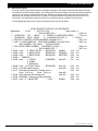
SECURITY CONTROL RECEIVER
MODEL SCS-1
INSTALLATION AND USER'S GUIDE
Copyright © 1986 – 1994 Digital Monitoring Products, Incorporated
Information furnished by DMP is believed to be accurate and reliable.
This information is subject to change without notice.
TABLE OF CONTENTS
4
5
6
Section
Model SCS-208 Power Cord
Description and Installation ......................................................... 3.8
Model SCS-203 Convenience Panel
Description .................................................................................. 3.9
Installation ................................................................................... 3.9A
Model SCS-PTR Printer and Cable
Description .................................................................................. 3.10
Installation ................................................................................... 3.10A
Printer Configuration ................................................................... 3.10B
Model SCS-CRT Video Display , Keyboard, and Cable
Description .................................................................................. 3.11
Installation ................................................................................... 3.11A
CRT Configuration ....................................................................... 3.11B
Special Keys ................................................................................ 3.11C
System Block Diagram
OPERATOR'S GUIDE
Principle Terms For The Security Control ................................... 4.1
How To “Talk” To The Security Control ....................................... 4.2
Alarm Acknowledge ..................................................................... 4.3
Additional Signal Holding ............................................................ 4.4
Operator Signon .......................................................................... 4.5
Operator Signoff .......................................................................... 4.6
Set System Time/Day/Date ......................................................... 4.7
Network Definitions ..................................................................... 4.8
Operator Codes ........................................................................... 4.9
Configure System ........................................................................ 4.10
Redisplay Non-Restored Status .................................................. 4.11
PRINTOUT EXPLANATIONS
General Description ......................................................................... 5.1
System Messages
Description .................................................................................. 5.2
Operator Signon/Signoff .............................................................. 5.3
Time/Day/Date ............................................................................ 5.4
Operator Codes ........................................................................... 5.5
System Number ........................................................................... 5.6
Telephone Line Configuration ..................................................... 5.7
Network Definitions ..................................................................... 5.8
Command Processor Messages
Description .................................................................................. 5.9
Alarm, Trouble and Restore ........................................................ 5.10
Ambush ....................................................................................... 5.11
Opening and Closing Reports ..................................................... 5.12
Bypass and Reset ....................................................................... 5.13
Add and Delete Codes ................................................................ 5.14
Schedule Changes ...................................................................... 5.15
Door Access ................................................................................ 5.16
Supervisory Messages ................................................................ 5.17
Explanations for Selected Supervisory Messages ...................... 5.18
Acknowledgment of Fire and Supervisory Alarms & Troubles .... 5.19
Message Destinations ................................................................. 5.20
ERROR MESSAGES AND PRINTER TROUBLESHOOTING
Error Messages
Description .................................................................................. 6.1
Access Denied! ........................................................................... 6.2
Changing Line Type Will Cause Network.. .................................. 6.3
*End of Job* ................................................................................ 6.4
Invalid Code! Try Again ............................................................... 6.5
Invalid Response! ........................................................................ 6.6
Invalid Selection! ......................................................................... 6.7
Operator Memory Full! ................................................................ 6.8
Operator Which is Signed On May Not Be Erased! .................... 6.9
Activity Log Error ......................................................................... 6.10
1 - SYSTEM OVERVIEW
SYSTEM OVERVIEW
1.1
Description
The SCS-1 Receiver system from DMP is comprised of a full featured digital/multiplex capable alarm receiver, a CRT
display for viewing incoming reports, a local 80 character printer, and a detachable keyboard for acknowledging
reports and configuring the SCS-1 system and its components.
1.2
Function
The SCS-1 Receiver system provides central stations with computerized monitoring of DMP command processor
panels. Features of the SCS-1 receiver include automatic logging of alarm, trouble, and supervisory account reports
on a local printer with the date and time of their occurrence.
1.3
CRT Display
The CRT display adds flexibility to the SCS-1 system by allowing the operator to view alarm reports before
acknowledging them from the system keyboard. A typical account report includes:
Account Number 12345
Loop Name FRONT DOOR, BACK DOOR
Alarm Type Burglary, Fire, Panic
Time and Date of occurrence
All information is displayed on the CRT screen and logged on the local printer. Opening and Closing reports from
monitored accounts provide the operator with:
Account Number 12345
Area Numbers and Names - Area: 1 OFFICE
Area: 2 STOCKROOM
User Number of Individual - Disarmed by User #25
Time and Date of Occurrence
1.4
Printer
Routine reports are logged on the printer without need of operator response while supervisory reports are logged on
the printer and displayed on the CRT console for operator acknowledgment.
1.5
Additional Reports
Other reports transmitted to the SCS-1 by DMP Command Processor panels include:
• Addition and deletion of code numbers including user number of the person making the change
• Bypass and reset of zones by number and name including user number of the person making the change
• Schedule changes including user number of the person making the change
• Trouble and Restoral report by zone name and number
• Door access reports including user number and number of the door being accessed
Section 5 of this guide provides a detailed explanation of the alarm and activity reports that can be logged on the
SCS-1 printer or displayed on the CRT.
1.6
Line Capacity
The SCS-1 Receiver accommodates up to five incoming phone lines. Each SCS-1 can be configured with both digital
dialer and multiplex receiving lines. Multiplex lines have a capacity of 128 separate accounts. Digital Dialer lines have
a capacity of 65,535 separate accounts.
To select the communication type used on each incoming line, refer to Configure System in section 4.10.
1.7
24 Hour Recall Tests
The automatic recall test from a digital dialer account must be tracked manually or with a listed automation system.
The SCS-1 Receiver does not automatically indicate a delinquent recall test. Failure to receive a signal from a Digital
Alarm Communicator Panel (DACT), over a 24 hour period shall be handled as a trouble signal.
SCS-1 Install/User's Guide
2841 E. Industrial Drive Springfield, MO 65802-6310 800-641-4282
1
2 - INSTALLATION
INSTALLATION CHECKLIST
2.1
Cover Plates
Remove the front plastic cover by twisting the four knobs 90 degrees. Remove the two metal rear cover plates. The
lower rear cover plate attaches to the three flat cables of the convenience panel.
2.2
Earth Ground
Connect the ground lug on the rear side of the modem rack to earth ground. See Section 3.2. A ground lug is provided
on the SCS-1 for this purpose. Use a minimum of 14 gauge wire and ground to a cold water pipe or a ground rod.
Do not ground to electrical conduit or telephone company ground.
2.3
Location of Circuit Boards
Confirm the circuit boards in the modem rack and in the multibus rack are installed in the proper locations. See Section
3.2. Connect the line card flat cables to the processor card ports. See Section 3.4A.
2.4
SCS-208 Power Cord
Connect the SCS-208 Power Cord from J3 of the multibus power supply card to J3 of the transformer card. See
Section 3.8.
2.5
Phone Lines
Connect the RJ11X cables provided with each line card to the phone lines used for alarm receiving. See Section 3.4B.
2.6
AC Power
Connect the wiring for 120 VAC to the transformer card mounted on the rear of the modem rack. See Section 3.7B.
Do not apply AC power yet. For UL Listed operation, use a UL Listed uninterruptible power supply. The UPS system
must have a secondary power source and provide alarm contacts to indicate when the UPS switches from primary
power to secondary power. Below is a list of UL listed UPS systems that provide the correct alarm contacts.
Best Power
Technology
Any Series M or
Models
F2KVA-B
F3KVA-B
F5KVA-B
Clary Corp.
Any Series A-52
Elgar
Models
La Marche
Any Series A-52
Topaz
Any Series 82000
Models
84462-01
84864-01
84126-01
84130-01
UPS253-3B
UPS373-3B
UPS503-3B
Other UL listed UPS systems that provide alarm contacts to indicate loss of primary power can be used.
SCS-1 Install/User's Guide
2841 E. Industrial Drive Springfield, MO 65802-6310 800-641-4282
2
2 - INSTALLATION
2.7
Front and Rear Covers
Replace the front plastic cover and the two metal rear covers. The louvered rear cover mounts on top.
2.8
CRT Display
Connect the CRT Display, Keyboard, and RS-232 cable. See Sections 3.11B and 11.5. Connect the CRT to AC
power and turn on the CRT power switch. The CRT must be located adjacent to the SCS-201 Cabinet for UL Listed
operation.
2.9
Printer
Connect the printer RS-232 cable. See Section 3.10A. Install paper, connect the printer to AC power, and turn on
the printer power switch.
2.10
Start up
Apply 120 VAC to the transformer card. The 120 volts supplied to the receiver, the CRT display and the printer(s)
must be from the same UPS circuit.
2.11
Configuration
After powering up the system, set the correct time, configure the phone lines, and enter the operator codes. Refer
to Section 4 in this manual for instructions on completing the above tasks.
SCS-1 Install/User's Guide
2841 E. Industrial Drive Springfield, MO 65802-6310 800-641-4282
3
3 - HARDWARE DESCRIPTION
MODEL SCS-1 SECURITY CONTROL RECEIVER
3.1
Description
The DMP SCS-1 Receiver as shipped from the factory includes all of the necessary system components to
provide two lines of receiving capability. This package can be expanded to a maximum of five incoming lines.
The SCS-1 includes the following:
Quantity
1
1
2
1
1
1
1
1
1
1
Model Number
SCS-201
SCS-1062
SCS-100
SCS-110
SCS-120
SCS-130
SCS-208
SCS-203
SCS-PTR
SCS-CRT
Name
System Enclosure
Processor Card
Line Card
Modem Power Supply Card
Multibus Power Supply Card
Transformer Card
Power Cord
Convenience Panel
Printer and Cable
CRT Display, Keyboard and Cable
A detailed installation and operational description for each component follows in this section.
MODEL SCS-201 SYSTEM ENCLOSURE
3.2
Description
The SCS-201 provides housing for the receiver processor, power supply, line cards, and associated cables. The
enclosure measures 13" deep, 9.75" high and 20" wide.
3 Amp
Fuse
SCS-110
Modem Power Supply
115 Volt
AC Input
SCS-100
Line Cards
SCS-120
Multibus
Power Supply
SCS-1062
Processor
SCS-130
Transformer
Card
Modem
Rack
Front View
Multibus
Rack
Ground Lug
Rear View
Fan
3.2A Modem Rack
Contained in the top of the System Enclosure is a 5.25" modem rack. The rack holds the modem power supply
card and up to five line cards. The transformer card for connecting the 120 VAC is mounted on the rear of the
modem rack.
3.2B Multibus Rack
Contained in the bottom of the System Enclosure is a 3.5" multibus rack with cooling fan. The multibus rack
holds the processor card and the multibus power supply card.
3.2C Installation
Connect the System Enclosure to earth ground before making any connections to the modules. Use a minimum
14 gauge wire for grounding. A crimp type spade connector is provided for connecting the ground wire to the
ground lug on the modem rack.
SCS-1 Install/User's Guide
2841 E. Industrial Drive Springfield, MO 65802-6310 800-641-4282
4
3 - HARDWARE DESCRIPTION
3.4A Card Installation
Install the SCS-100 with the card puller up in any one of the five right hand positions of the modem rack.
Connect the 10 position flat cable between the line card and the processor card.
PIN 1 OF THE FLAT CABLE CONNECTOR MUST BE IN THE SAME POSITION ON BOTH THE LINE
CARD AND THE PROCESSOR CARD.
The line number of the line card is determined by the processor card port number.
3.4B Phone Line Installation
Install the RJ11X cable provided with the line card between the RJ11X connector on the front of the line card to
a customer supplied RJ11X jack. Use a standard 103J voice grade line. A slot is provided in the receiver back
plate for the RJ11X cable to pass through.
The SCS-100 is registered with the FCC, registration number CCK8GW-16197-AL-N;
Ringer Equivalence 1.2.
3.4C Phone Line Monitor
The incoming phone line voltage is monitored when the Line Card is configured for digital dialer operation.
During a loss of phone line voltage, the red Phone Line Fail LED is lit and the alert sounds. The alert can be
silenced by pressing the silence switch on the line card. The LED remains lit until the phone line is restored.
3.4D Configuration for MPX or DD
The SCS-100 can be used for either digital dialer or multiplex communication. To change configuration, set the
four jumpers labeled J1, J2, J3, and J4 to the appropriate position. For multiplex communication, set the jumper
labeled J10 for either 2-wire or 4-wire operation. For 4-wire operation, the yellow and black wires of the RJ11X
cable become the receive pair for multiplex.
Always set Jumper J10 for 2-wire operation when using digital dialer communication.
3.4E Power Monitor LED
The green LED labeled PWR is lit when the power supply on the line card is in a good condition.
3.4F Data Communication LEDs
The six yellow LEDs indicate the condition of the line card during the various stages of communication.
A description of each LED is listed below:
TD
Transmit Data
On when the line card is transmitting to a panel.
RD
Receive Data
On when the line card is receiving data from a panel.
CD
Carrier Detect
On when the carrier tone from the panel is detected on the
phone line.
OL
On Line
On when a line card configured for digital dialer has answered
the phone line. Not used for MPX.
RG
Ring Detect
On when ringing voltage is detected on phone line. Not used
for MPX.
DT
Data Terminal Ready
On when the line card is ready to receive.
SCS-1 Install/User's Guide
2841 E. Industrial Drive Springfield, MO 65802-6310 800-641-4282
6
3 - HARDWARE DESCRIPTION
MODEL SCS-120 MULTIBUS POWER SUPPLY CARD
3.6
Description
The SCS-120 provides power to the processor card through the multibus backplane. The SCS-120 also monitors
the condition of the processor card, the voltage output of the modem power supply card, and its own internal
voltages.
SCS-1062
PROCESSOR
+5
+12
OK
MODEM
POWER
TRBL
OK
TRBL
OK
TRBL
TRBL
POWER
ALERT
SILENCE
OK
FAIL
RESTART
J3
-12
3.6A Installation
Always disconnect power to the receiver when installing or removing the SCS-120. Install the board with the
component side up in the upper position of the multibus rack. Connect the SCS-208 Power Cable to J3 on the
front right side of the card. Connect the other end of the power cable to the transformer card on the back of the
modem rack. The power cable can be used in either direction.
3.6B Processor Monitor
The SCS-120 monitors the processor of the Model SCS-1062 through the multibus backplane. The green OK
LED lights when the processor is operating. If the processor stops operating, the red FAIL LED lights and the
failure buzzer on the SCS-120 sounds. Press the processor restart button to restart the system, silence the
buzzer, and turn off the red LED. The restart button restarts the system and resets the time of day. All other
system configuration information is not changed.
3.6C Power Monitor LEDs
The SCS-120 monitors three different system voltages, +5, +12, -12 and the modem power supply. Four LEDs
located to the right of the power trouble silence switch display any voltage failure. A green OK LED lights when
the voltages are in good condition. The green PWR LED for the modem power supply is located on the modem
power supply card. The red TRBL LED lights and the trouble alert on the SCS-120 sounds when there is a
problem with a voltage level.
Press the power trouble silence switch to silence the alert. The red TRBL LED remains lit until the power
problem is corrected. The modem power LED, the trouble alert on the SCS-120, and the power trouble LED on
the modem power supply operate together.
SCS-1 Install/User's Guide
2841 E. Industrial Drive Springfield, MO 65802-6310 800-641-4282
8
3 - HARDWARE DESCRIPTION
MODEL SCS-203 CONVENIENCE PANEL
3.9
Description
The SCS-203 provides cabling for three RS-232 ports. The three ports are for the CRT display, host output, and
activity log printer.
To
CRT
To
SCS-110
To
Port 7
To
Host Computer
To Port 8
To Port 6
To
Activity Log
Printer
3.9A Installation
Install the three 10 position flat cable connectors to ports 6, 7 and 8 of the processor card. Install the metal plate
with the three 25 position RS-232 connectors on the receiver backplate using the two 6-32 x 1/4" screws
provided. Connect the CRT display, printers and/or host computer to the RS-232 connectors.
MODEL SCS-PTR PRINTER AND CABLE
3.10 Description
The SCS-PTR is an 80 column printer with a 10' RS-232 cable. The printer can be connected to the all events
output connector or the alarm only output connector. See Section 3.9. The SCS-1 Receiver is shipped with one
printer.
3.10AInstallation
The printer as shipped by DMP has all option switches preset. Install the RS-232 cable between the printer serial
interface port and the receiver convenience panel connector. Remove any dummy plugs from the printer output
connector. If a printer is not being installed, the dummy plug shorting pins 4 and 5 should remain on the
connector.
THE END OF THE CABLE MARKED PRINTER MUST BE INSTALLED INTO THE PRINTER.
3.10BPrinter Configuration
Set the printer option switches on the Okidata ML 184T according to the tables below:
Upper Serial Board
Lower Control Board
Switch Bank 1
Switch Bank 2
Switch Bank 1
1 OFF EVEN PARITY
1 ON
1 OFF
2 ON WITHOUT PARITY
2 ON 1200 BAUD
2 OFF ASCII
3 ON 8 BITS
3 OFF
3 OFF
4 ON READY/BUSY
4 OFF DSR
4 OFF
5 ON CIRCUIT/MONITOR
5 ON 32 BYTES BUFFER
5 ON
6 ON PRINT MODE
6 ON 200ms BUSY SIGNAL
6 ON AUTO LINE FEED
7 OFF
7 OFF DTR
7 ON 8 BITS
8 ON
8 OFF NOT USED
8 OFF ENABLE FRONT PANEL
SCS-1 Install/User's Guide
2841 E. Industrial Drive Springfield, MO 65802-6310 800-641-4282
10
3 - HARDWARE DESCRIPTION
120 VAC INPUT
UPS BROWNOUT INPUT
J1
MODEL SCS-130
J2
TRANSFORMER CARD
COOLING
FAN
MODEL SCS-110
MODEM RACK
SUPPLY CARD
J3
MODEL SCS-208
POWER CABLE
MODEM RACK BACKPLANE
J3
10 CONDUCTOR
FLAT CABLE
MODEL SCS-120
MULTIBUS POWER
SUPPLY CARD
RJ11X CABLE
MODEL SCS-100
LINE CARD
LINE 1
MODEL SCS-100
LINE CARD
LINE 2
MULTIBUS BACKPLANE
PORT 1
PORT 2
MODEL SCS-1062
PROCESSOR CARD
PORT 3
MODEL SCS-100
LINE CARD
LINE 3
MODEL SCS-100
LINE CARD
LINE 4
PORT 4
PORT 5
PORT 6
7
8
MODEL SCS-100
LINE CARD
MODEL SCS-203
CONVENIENCE
PANEL
MODEL SCS-PTR
PRINTER AND
CABLE
MODEL SCS-CRT
CRT DISPLAY
AND KEYBOARD
LINE 5
HOST COMPUTER
SCS-1 Install/User's Guide
2841 E. Industrial Drive Springfield, MO 65802-6310 800-641-4282
12
4 - OPERATOR'S GUIDE
4.1
Principle For The Security Control
This is an alphabetical list of terms used in the SCS-1 Receiver system operating instructions.
An operator can refer to these explanations for additional information.
\ (Back slash)
A key located on the Security Control keyboard used to acknowledge
messages as they're displayed on the CRT.
Alphanumeric
A set of characters consisting of either the letters A through Z, the digits
0 through 9, special symbols, or a combination of all of these. For
example: the set of characters "AB76#2", is alphanumeric.
Character
One of a set of symbols that can be arranged in groups to express
information. This includes the digits 0 through 9, the letters A through
Z, punctuation marks, and other special symbols.
Command Processor
Programs
The data programmed into a DMP command processor panel at the
time of installation. A typical program includes: communication information, system options, area information, loop information, and the
number and type of Security Command keypads in the system.
This should not be confused with System Programs that are software
routines used by the SCS-1 to execute functions described in the
Operations Manual.
CRT
A computer monitor used to display information and a computer
keyboard that allows you to enter information.
Cursor
A flashing underline symbol on the CRT display for use when entering
or changing information.
Default Value
A value assigned to a field by the SCS-1. The receiver assigns the
value to that field allowing the operator to accept its entry and respond
to the next field.
Del (Delete)
A key located on the SCS-1 keyboard that clears the information
currently in the cursor location. The cursor then moves to the next field.
The use of this key varies between programs.
Entry
Information typed into the SCS-1 through the keyboard attached to the
CRT. This information is entered into the system when the Return key
is pressed.
Field
A single item of information on a CRT screen. For example: a field
within the System Configuration program would be the company
name. Another field in this selection would be the type specification for
line 2.
Menu
A CRT display that lists the program selections available to the
operator.
SCS-1 Install/User's Guide
2841 E. Industrial Drive Springfield, MO 65802-6310 800-641-4282
13
4 - OPERATOR'S GUIDE
4.2
Numeric
Description of numerical information. For example: the set of characters 1 2 3 4 5 is numeric.
Down Cursor
A key located on the SCS-1 keyboard that moves the cursor back to
the previous field allowing you to change a previous entry.
Esc
A key located on the SCS-1 keyboard that terminates the current
selection and returns you to the System Menu.
User Number
The sequential number assigned to each user code number by the
panel during its programming. This is the number transmitted to the
SCS-1 Receiver. The actual code number is never transmitted.
How to Operate the Security Control
Entering information into the SCS-1 is simple. The CRT first displays a message, or prompt, indicating that
information needs to be entered in a field. After you type in the information, press the return key to allow the
system to start processing your entry and move the cursor to the next field.
If you make a mistake while typing information, use the BACKSPACE key to move the cursor under the
character you want to change and then type in the correct information. To change an entire word or series of
characters, move the cursor under the first letter of the word or first character and type in the correct information.
There are three special keys to help you enter information: Down Cursor, Esc, and Del. See Section 3.11C
Special Keys.
The Down Cursor key backs up the cursor to the previous FIELD allowing you to change information already
entered.
The Esc key allows you to terminate the current selection and return to the System Menu.
The Del key allows you to delete all data contained in the FIELD designated by the cursor. The Del key may not
work in some fields; it's correct use is given at the beginning of each program description.
Detailed instructions on how to operate the system programs are contained on the following pages.
SCS-1 Install/User's Guide
2841 E. Industrial Drive Springfield, MO 65802-6310 800-641-4282
14
4 - OPERATOR'S GUIDE
4.3
Alarm Acknowledge
Any time an emergency message is received by the SCS-1 Receiver, the keyboard locks, an alert sounds and a
message is displayed similar to the example shown below. The alert continues to sound until the \ (Back slash)
key is pressed on the keyboard acknowledging the alarm. The keyboard then returns to normal operation.
After an emergency message has been acknowledged it's written over by the next emergency message. Refer to
Section 5, PRINTOUT EXPLANATIONS, for a description of the various messages that can be displayed for
acknowledgment.
1-12345 LOOP: 10 FRONT DOOR-BURGLARY ALARM
10:56 a.m.
ENTER SELECTION:
SCS-1 Install/User's Guide
2841 E. Industrial Drive Springfield, MO 65802-6310 800-641-4282
15
4 - OPERATOR'S GUIDE
4.4
Additional Signal Holding
When any emergency message is being displayed for acknowledgment and a second emergency message is
received, Additional Signal Holding is displayed on line 2 of the CRT display.
This message remains displayed until only one message remains to be acknowledged.
When more than one message is holding in the receiver memory, the messages are prioritized for display in the
following order:
1)
2)
3)
4)
5)
Fire alarms
Panic and Burglary alarms
Supervisory, Emergency and Auxiliary alarms
Fire and Burglary troubles and restorals
Other messages
1-12345 LOOP: 10 FRONT DOOR- BURGLARY ALARM 10:56 a.m.
Additional Signal Holding
ENTER SELECTION:
SCS-1 Install/User's Guide
2841 E. Industrial Drive Springfield, MO 65802-6310 800-641-4282
16
4 - OPERATOR'S GUIDE
4.5
On - Operator Signon
This selection allows you to access the system programs. The programs available on the SCS-1 are: Set System
Time/Day/Date, Network Definitions, Operator Codes, and Configure System. To sign on, type ON and press
RETURN.
The operator’s name is logged on the ACTIVITY LOG printer. The following page shows the sequence for
signing on.
ENTER SELECTION:
ON
OPERATOR SIGNON
SCS-1 Install/User's Guide
2841 E. Industrial Drive Springfield, MO 65802-6310 800-641-4282
17
4 - OPERATOR'S GUIDE
OPERATOR SIGNON - ON
REMEMBER:
-Use RETURN to enter a field and to move to the next field.
-The next field does not appear until the previous field is entered.
FIELD NAME
ENTER OPERATOR CODE:
OPERATOR RESPONSE
Enter your operator code and press RETURN. The system menu is
then displayed.
If this is the first time the system has been used, type NEW to gain
access to the system menu.
The operator code is not displayed as it is entered.
ENTER OPERATOR CODE:
SCS-1 Install/User's Guide
2841 E. Industrial Drive Springfield, MO 65802-6310 800-641-4282
18
4 - OPERATOR'S GUIDE
4.6
Off - Operator Signoff
This selection allows you to exit the system programs. This selection must be made before a new operator can
sign on.
The operator’s name is logged on the ACTIVITY LOG printer after signing off.
ENTER SELECTION:
OFF
TDD
NET
OPC
CON
RED
OPERATOR SIGNOFF
SET SYSTEM TIME/DAY/DATE
NETWORK DEFINITIONS
OPERATOR CODES
CONFIGURE SYSTEM
REDISPLAY NON-RESTORED STATUS
SCS-1 Install/User's Guide
2841 E. Industrial Drive Springfield, MO 65802-6310 800-641-4282
19
4 - OPERATOR'S GUIDE
4.7
TDD - Set System Time/Day/Date
This selection allows you to set the correct time, day, and date on the SCS-1. All changes made in this selection
are logged on the ACTIVITY LOG printer.
ENTER SELECTION:
OFF
TDD
NET
OPC
CON
RED
OPERATOR SIGNOFF
SET SYSTEM TIME/DAY/DATE
NETWORK DEFINITIONS
OPERATOR CODES
CONFIGURE SYSTEM
REDISPLAY NON-RESTORED STATUS
SCS-1 Install/User's Guide
2841 E. Industrial Drive Springfield, MO 65802-6310 800-641-4282
20
4 - OPERATOR'S GUIDE
SET SYSTEM TIME/DAY/DATE - TDD
REMEMBER:
-Use the Down Cursor to go back one field.
-Use Esc to exit the current program.
-Del has no function in this selection.
-Use Return to enter a field and step to the next field.
-The next field does not appear until the previous field is entered.
FIELD NAME
OPERATOR RESPONSE
ENTER TIME:
Enter the time. For example: 2:30 pm
DAY:
Enter the day of the week.
DATE:
Enter the month, date, and year. (MM/DD/YY)
After this entry, the system menu returns automatically.
ENTER TIME:
DAY:
DATE:
SCS-1 Install/User's Guide
2841 E. Industrial Drive Springfield, MO 65802-6310 800-641-4282
21
4 - OPERATOR'S GUIDE
4.8
NET - Network Definitions
This selection allows you to assign Multiplex command processor numbers to the SCS-1. Telephone lines to
which Multiplex account numbers are assigned must have the correct type specification in the Configure System
program.
A Multiplex communication system polls up to 128 accounts on each telephone line. Assigning each account
number in service to a line on the SCS-1 ensures only valid accounts are polled. This speeds up communication
cycles.
Since digital dialers initiate the communication to the receiver and are not polled, it is not necessary to assign
digital dialer account numbers to a line. Telephone lines specified as DD will not accept account number
assignments.
The entire line specification is logged on the ACTIVITY LOG printer when any item in the configuration is
changed.
ENTER SELECTION:
OFF
TDD
NET
OPC
CON
RED
OPERATOR SIGNOFF
SET SYSTEM TIME/DAY/DATE
NETWORK DEFINITIONS
OPERATOR CODES
CONFIGURE SYSTEM
REDISPLAY NON-RESTORED STATUS
SCS-1 Install/User's Guide
2841 E. Industrial Drive Springfield, MO 65802-6310 800-641-4282
22
4 - OPERATOR'S GUIDE
NETWORK DEFINITIONS - NET
REMEMBER:
PAGE 1
-Use the Down Cursor to go back one field.
-Use Esc to exit the current program.
-Use Return to enter a field and step to the next field.
-The next field does not appear until the previous field is entered.
-Del has no function in this selection.
FIELD NAME
LINE NUMBER:
OPERATOR RESPONSE
After making the NET selection, you'll be asked
for the line number to which account numbers will be
assigned. Enter the correct line number.
If the line number entered has a type specification of MPX, continue on
PAGE 2 of this section.
LINE NUMBER:
SCS-1 Install/User's Guide
2841 E. Industrial Drive Springfield, MO 65802-6310 800-641-4282
23
4 - OPERATOR'S GUIDE
NETWORK DEFINITIONS - NET (Multiplex Line)
FIELD NAME
DO YOU WISH TO ADD-DELETE
OR DISPLAY? (A,D):
PAGE 2
OPERATOR RESPONSE
If A is entered, you'll be asked for a panel number.
Refer to PAGE 3 of this section for the correct response.
If D is entered, all Multiplex panel numbers assigned
to this line will be displayed on the CRT screen.
DO YOU WISH TO ADD-DELETE OR DISPLAY? (A,D):
LINE NUMBER:
ACCOUNT NUMBER RANGE:
NEXT PANEL NUMBER AVAILABLE:
TOTAL PANEL NUMBERS IN USE:
SCS-1 Install/User's Guide
2841 E. Industrial Drive Springfield, MO 65802-6310 800-641-4282
24
4 - OPERATOR'S GUIDE
NETWORK DEFINITIONS - NET (Multiplex Line)
FIELD NAME
ENTER PANEL NUMBER:
PANEL NUMBER NOT
ASSIGNED. DO YOU
WISH TO ADD IT?
PAGE 3
OPERATOR RESPONSE
If the panel number entered is not previously assigned,
the following field is displayed:
If the response is Y, the panel number is
assigned and the information fields are updated.
The cursor returns for another panel number.
An N response returns the cursor for another
panel number.
If the panel number entered is already assigned, the
following field is displayed:
PANEL NUMBER ALREADY
ASSIGNED. DO YOU WISH
TO DELETE IT?
If the response is Y, the panel number is deleted
and the information fields are updated. The cursor
returns for another number. An N response
returns the cursor for another panel number.
ENTER PANEL NUMBER:
LINE NUMBER:
ACCOUNT NUMBER RANGE:
NEXT PANEL NUMBER AVAILABLE:
TOTAL PANEL NUMBERS IN USE:
SCS-1 Install/User's Guide
2841 E. Industrial Drive Springfield, MO 65802-6310 800-641-4282
25
4 - OPERATOR'S GUIDE
NETWORK DEFINITIONS - NET (DSAS Line)
FIELD NAME
DO YOU WISH TO ADD-DELETE
OR DISPLAY? (A,D):
PAGE 4
OPERATOR RESPONSE
If A is entered, you'll be asked for the port number
you wish to assign panel numbers to. Refer to PAGE 5
of this selection for the correct response.
If D is entered, all port and panel assignments
are displayed on the CRT screen.
DO YOU WISH TO ADD-DELETE OR DISPLAY? (A,D):
LINE NUMBER:
ACCOUNT NUMBER RANGE:
NEXT PANEL NUMBER AVAILABLE:
NEXT PORT AVAILABLE:
TOTAL PANEL NUMBERS IN USE:
TOTAL PORTS IN USE:
SCS-1 Install/User's Guide
2841 E. Industrial Drive Springfield, MO 65802-6310 800-641-4282
26
4 - OPERATOR'S GUIDE
NETWORK DEFINITIONS - NET (DSAS Line)
FIELD NAME
ENTER PORT NUMBER:
PAGE 5
OPERATOR RESPONSE
Enter the port number you're assigning a panel
number to. When entered, the port number is
displayed on the CRT screen with any panel
numbers that are assigned to it.
ENTER PORT NUMBER:
LINE NUMBER:
ACCOUNT NUMBER RANGE:
NEXT PANEL NUMBER AVAILABLE:
NEXT PORT AVAILABLE:
TOTAL PANEL NUMBERS IN USE:
TOTAL PORTS IN USE:
SCS-1 Install/User's Guide
2841 E. Industrial Drive Springfield, MO 65802-6310 800-641-4282
27
4 - OPERATOR'S GUIDE
NETWORK DEFINITIONS - NET (DSAS Line)
PAGE 6
FIELD NAME
ENTER PANEL NUMBER:
NOT ASSIGNED. DO YOU
WISH TO ADD TO PORT XX?
OPERATOR RESPONSE
When a panel number is entered, the SCS-1 checks to see if it
is already assigned to a port. If it's not assigned, the following
field is displayed:
If the response is Y, the panel number is
assigned to the port on the CRT display and all
information fields are updated. The cursor
returns for another port number. A N response
returns for another port number.
If a panel number entered is already assigned to a
port the following field is displayed:
ALREADY ASSIGNED TO
PORT XX. DO YOU WISH
TO DELETE?
If the response is Y, the panel number is deleted
from the port it's assigned to and all information
fields are updated. The cursor returns for another
port number. An N response returns for another
port number.
ENTER PANEL NUMBER:
LINE NUMBER:
ACCOUNT NUMBER RANGE:
NEXT PANEL NUMBER AVAILABLE:
NEXT PORT AVAILABLE:
TOTAL PANEL NUMBERS IN USE:
TOTAL PORTS IN USE:
PORT XX:
YY
ZZ
SCS-1 Install/User's Guide
2841 E. Industrial Drive Springfield, MO 65802-6310 800-641-4282
28
4 - OPERATOR'S GUIDE
4.9
OPC - Operator Codes
This selection allows you to add and delete operator codes. This entry consists of three parts; the operator name
or initials, code, and access level. The table below shows the different functions that are available to the different
code levels:
Table A
No Code
Level 1 to 4
X
X
Signon
Redisplay Non-Restored Status
Acknowledge Alarms
Set System Time Day and Date
Level 5 to 7
Level 8
Level 9
X
X
X
X
X
X
X
X
X
X
X
X
X
X
X
X
Network Definitions
Configure System
X
Operator Codes
X
Any addition or deletion of operator names or changes in
access level are logged on the ACTIVITY LOG.
ENTER SELECTION:
OFF
TDD
NET
OPC
CON
RED
OPERATOR SIGNOFF
SET SYSTEM TIME/DAY/DATE
NETWORK DEFINITIONS
OPERATOR CODES
CONFIGURE SYSTEM
REDISPLAY NON-RESTORED STATUS
SCS-1 Install/User's Guide
2841 E. Industrial Drive Springfield, MO 65802-6310 800-641-4282
29
4 - OPERATOR'S GUIDE
OPERATOR CODES - OPC
REMEMBER: -Use the Down Cursor to go back one field.
-Use Esc to exit the current program.
-Use Del to delete entire lines.
-Use Return to enter a field and step to the next field.
-The next field does not appear until the previous field is entered.
FIELD NAME
OPERATOR RESPONSE
SYSTEM NUMBER:
The correct system number is displayed for reference
only and cannot be changed from this program.
OPERATOR:
Enter the operator name or initials, maximum of 4 alphanumeric
characters. If the name does not exist, it is added to the list.
If it does exist it is highlighted and the corresponding code or
level can be changed. Press Del to delete the operator
name and corresponding code and level.
CODE:
Enter the operator code, maximum of 8 alphanumeric characters.
LEVEL:
Enter the operator level 1 to 4, 5 to 7, 8, or 9. After this entry, the
cursor returns for the next operator name. Press Esc for return
to the system menu.
NOTE: If an operator name is entered
without a code or level, the system
automatically enters a code of ******** and a level of 1.
SYSTEM NUMBER:
OPERATOR:
OPERATOR
CODE:
CODE
LEVEL:
LEVEL
SCS-1 Install/User's Guide
2841 E. Industrial Drive Springfield, MO 65802-6310 800-641-4282
30
4 - OPERATOR'S GUIDE
4.10 CON - Configure System
This selection is made to assign the company name and system number as well as the communication type for
each incoming telephone line on the SCS-1 Receiver.
ENTER SELECTION:
OFF
TDD
NET
OPC
CON
RED
OPERATOR SIGNOFF
SET SYSTEM TIME/DAY/DATE
NETWORK DEFINITIONS
OPERATOR CODES
CONFIGURE SYSTEM
REDISPLAY NON-RESTORED STATUS
SCS-1 Install/User's Guide
2841 E. Industrial Drive Springfield, MO 65802-6310 800-641-4282
31
4 - OPERATOR'S GUIDE
CONFIGURE SYSTEM - CON
REMEMBER:
PAGE 1
-Use the Down Cursor to go back one field.
-Use Esc to exit the current program.
-Use Del to clear phone number, bill number and comment fields.
-Use Return to enter a field and step to the next field.
-The next field does not appear until the previous field is entered.
FIELD NAME
OPERATOR RESPONSE
COMPANY NAME:
Enter your company name up to 40 characters.
SYSTEM NUMBER:
Enter the number of this system. NOTE: This is not
the operational level of the system but an identifier to
distinguish between multiple Systems.
KEY:
Enter your company receiver key. Note: this is an eight
character alphanumeric field. This key is requested by
command processor control panels in the field when remote
programming is being done. Once entered this key will
not display and it should never be changed.
CO NAME:
SYSTEM NO:
KEY:
COMPANY NAME
SYSTEM NUMBER
SCS-1 Install/User's Guide
2841 E. Industrial Drive Springfield, MO 65802-6310 800-641-4282
32
4 - OPERATOR'S GUIDE
CONFIGURE SYSTEM - CON
PAGE 2
FIELD NAME
OPERATOR RESPONSE
LINE NO.
is to be specified.
Enter the line number for which the communication method
TYPE:
Enter the communication method.
MPX = Multiplex
DD
= DMP Digital Dialer
ASYN = Asynchronous communication
NONE = Clear all information for the line.
PHONE NUMBER:
Enter phone number of digital dialer line.
Maximum 13 characters.
BILL NUMBER:
Enter the bill number for this phone line.
Maximum 10 characters.
LINE NO:
COMPANY NAME
SYSTEM NUMBER
LINE TYPE
PHONE NUMBER
BILL NUMBER
COMMENT
ERR% CALLS
1
.00
0
2
.00
0
3
.00
0
4
.00
0
5
.00
0
HOST MESSAGES:
0
SCS-1 Install/User's Guide
2841 E. Industrial Drive Springfield, MO 65802-6310 800-641-4282
33
4 - OPERATOR'S GUIDE
CONFIGURE SYSTEM - CON
FIELD NAME
PAGE 3
OPERATOR RESPONSE
COMMENT:
After the bill number is entered, you can enter a comment
for this line, maximum 15 characters. After this entry, the
cursor returns for the next line number. Press Esc to
return to the system menu.
ERR%:
This is a display only field. It displays the percentage
of communication troubles by line since midnight.
CALLS:
This is a display only field. It displays the total number
of calls by line since midnight. If MPX, the number of
information frames is displayed.
HOST MESSAGES:
This is a display only field. It displays the total number
of reports sent to the host computer since midnight.
TYPE:
PHONE NUMBER
BILL NUMBER
COMMENT:
COMPANY NAME
SYSTEM NUMBER
LINE TYPE
PHONE NUMBER
BILL NUMBER
COMMENT
ERR% CALLS
1
.00
0
2
.00
0
3
.00
0
4
.00
0
5
.00
0
HOST MESSAGES:
0
SCS-1 Install/User's Guide
2841 E. Industrial Drive Springfield, MO 65802-6310 800-641-4282
34
4 - OPERATOR'S GUIDE
4.11 RED - Redisplay Non-restored Status
This selection is made to display fire and supervisory type loops that have not restored from an alarm or trouble
condition. The loops are listed in order by account number followed by loop number. When a restoral is received
for a loop, it is automatically removed from the list.
ENTER SELECTION:
OFF
TDD
NET
OPC
CON
RED
OPERATOR SIGNOFF
SET SYSTEM TIME/DAY/DATE
NETWORK DEFINITIONS
OPERATOR CODES
CONFIGURE SYSTEM
REDISPLAY NON-RESTORED STATUS
SCS-1 Install/User's Guide
2841 E. Industrial Drive Springfield, MO 65802-6310 800-641-4282
35
4 - OPERATOR'S GUIDE
REDISPLAY NON-RESTORED STATUS - RED
REMEMBER:
ACCOUNT
-Use Return to display the next page.
-Use Esc to exit the current program.
-The information displayed on the screen is current as of the moment Return is pressed. It
is not a “real time” display. To update the screen, press Return again.
LP# LOOP NAME
1-12345 48
1-40345
6
1-40376 16
TYPE
STAT
ACCOUNT
LP# LOOP NAME
TYPE STAT
SMOKE DET. Fire TRBL
WATER MON. Supv ALRM
HEAT DET. Fire ALRM
Press ENTER for next page, Press ESC to go back to the menu.
SCS-1 Install/User's Guide
2841 E. Industrial Drive Springfield, MO 65802-6310 800-641-4282
36
5 - PRINTOUT EXPLANATIONS
5.1
General Description
The SCS-1 prints out two general types of messages: changes in the system information and reports received
from DMP Command Processor panels. The message line for system changes is bracketed by double asterisks
with the time of occurrence printed at the far right. Reports from panels always list the account number first
followed by the message and the time of occurrence. The printout below is a typical page from the ACTIVITY
LOG printer. The sequential numbers to the left are for reference and do not appear on the printout.
The following pages describe the various messages that are listed by the SCS-1.
ATLAS SECURITY SERVICE, INCORPORATED
Wednesday
3/1/93
* * ACTIVITY LOG * *
Page number: 2
**
* * RICK SIGNED ON * *
* * 7:58 a.m.
* * OPERATOR: PAT
LEVEL:
8 ADDED TO OPERATOR CODES.
* * 7:59 a.m.
* * OPERATOR: DAVE LEVEL:
9 CHANGED TO LEVEL: 5.
* * 7:59 a.m.
* * SECURITY CONTROL SYSTEM NUMBER CHANGED TO: 1.
* * 8:01 a.m.
* * LINE: 3 CONFIGURED AS: DD PHONE NUMBER: (214) 555-1212
* * 8:02 a.m.
BILL NUMBER: 2141175000
DIGITAL DIALER
* * MULTIPLEX PANEL NUMBER: 108 ADDED TO LINE: 1
* * 8:04 a.m.
**
* * RICK SIGNED OFF * *
* * 8:07 a.m.
1-10001 Loop:
8 FRONT DOOR - BURGLARY
ALARM
8:18 a.m.
1-10000 Loop:
2 BACK DOOR
- BURGLARY
TROUBLE
8:23 a.m.
1-10000 Loop:
2 BACK DOOR
- BURGLARY
RESTORE
8:24 a.m.
1-10000 * * AMBUSH * *
8:27 a.m.
1-10058 Area:
1 OFFICE
- DISARMED
User #07
8:31 a.m.
2 PLANT
3 SHIPPING
1-10045 Loop: 10 FRONT DOOR
- BYPASSED
User #15
8:33 a.m.
1-10072 User #09 added to panel
User #02
8:33 a.m.
1-10117 Permanent schedule for Tuesday Area: 1
8:35 a.m.
Open: 8:00 a.m.
Close: 5:30 p.m.
User #05
1-12345 Door Access at Door Number 05
User #21
8:36 a.m.
1-10045 WARNING: Panel ground fault indication.
8:38 a.m.
1-10187 Loop: 37 SMOKE DET.
- * * ACK * *
ALARM
8:40 a.m.
SCS-1 Install/User's Guide
2841 E. Industrial Drive Springfield, MO 65802-6310 800-641-4282
37
5 - PRINTOUT EXPLANATIONS
5.2
System Messages
System messages are provided on the ACTIVITY LOG printer to provide a permanent record of changes made
to the system information. The operator making the change is determined by referring to the last sign on.
A detailed explanation of each message follows:
5.3
Operator Sign on/Sign off
This message is printed after an operator enters their code number to access the system menu. The name of the
operator and the sign on time are printed. The code number of the operator is not printed.
An example of this message is shown on line 3 of the sample printout. The same process is followed when the
operator signs off. A sign off example is shown on line 10 of the sample printout.
5.4
Time/Day/Date
When the time, day, or date is changed, the old and the new value are printed.
An example of a date change is shown below.
* * DATE CHANGED FROM: 1/1/82
TO: 9/1/82 * *
Time and day changes follow the same format.
5.5
Operator Codes
When a new operator is added to the system, the operator name and level are printed. An example is shown on
line 4 of the sample printout. Any time a current operator is deleted from the system a similar message is printed.
When only the operator level is changed, the old level and the new level are printed. An example is shown on
line 5 of the sample printout.
5.6
System Number
When the system number is changed, the new system number is logged. This is shown on line 6 of the sample
printout.
5.7
Telephone Line Configuration
Each time a change is made to any part of a line configuration, all parts of that configuration are printed. This
message is a 2-line format shown on lines 7 and 8 of the sample printout.
5.8
Network Definitions
Adding or deleting a Multiplex account from a Network Definition prints the panel number and line on the
ACTIVITY LOG printer. An example is shown on line 9 of the sample printout.
5.9
Command Processor Reports
Reports from Command Processor panels are sent to the SCS-1 advising of various changes in the panel status
in the field. The reports can be logged on the printer and/or displayed on the CRT. The proper logging of each
report is listed in Section 5.20.
5.10 Alarm, Trouble, and Restore
These reports are formatted the same. Alarm and Trouble messages are logged on both printers and displayed
on the CRT for acknowledgment.
Fire and Supervisory restorals are displayed on the CRT for acknowledgment and logged on the ACTIVITY LOG
while other restore messages are logged on the ACTIVITY LOG only.
An example of each report is shown on lines 11 to 13 of the sample printout.
SCS-1 Install/User's Guide
2841 E. Industrial Drive Springfield, MO 65802-6310 800-641-4282
38
5 - PRINTOUT EXPLANATIONS
5.11 Ambush
The Ambush report is logged on both printers and displayed on the CRT for acknowledgment.
An example of an Ambush report is shown on line 14 of the sample printout.
5.12 Opening and Closing Reports
Openings and Closings list the areas being armed or disarmed and the user number making the change. These
reports can be from 1 to 8 consecutive lines and are logged on the ACTIVITY LOG only.
An example of this report is shown on lines 15 to 17 of the sample printout.
5.13 Bypass and Reset
This report is printed in a one line format listing the zone number, zone name, and user number making the
change. The report is logged on the ACTIVITY LOG only.
An example of this message is shown on line 18 of the sample printout.
5.14 Add and Delete Codes
This report lists the user number added or deleted along with the user number of the individual making the
change. The report is logged on the ACTIVITY LOG only.
An example is shown on line 19 of the sample printout.
5.15 Schedule Changes
This is printed in a 2-line format listing the type of schedule (permanent or temporary), day of the week, opening
and closing time, and the user number making the change. This report is printed on the ACTIVITY LOG only.
An example is shown on lines 20 and 21 of the sample printout.
5.16 Door Access
This report lists the user number accessing the door strike relay and the door which is being accessed. The door
number matches the keypad address being operated by the user.
An example is shown on line 22 of the sample printout.
SCS-1 Install/User's Guide
2841 E. Industrial Drive Springfield, MO 65802-6310 800-641-4282
39
5 - PRINTOUT EXPLANATIONS
5.17 Supervisory Messages
All supervisory reports follow the same format. The account number, the report, and the time of occurrence.
An example is shown on the sample printout. The various supervisory reports are listed below:
WARNING: A.C. power failure
A.C. power restored
WARNING: Low standby battery
Standby battery restored
WARNING: Auxiliary fuse trouble
Auxiliary fuse restored
WARNING: Bell fuse trouble
Bell fuse restored
WARNING: Panel ground fault
Panel ground restored
WARNING: Bell circuit trouble
Bell circuit restored
WARNING: Panel tamper
Panel tamper restored
WARNING: Low communication line level
Communication line level restored
WARNING: Panel backup communication fail
Backup communication line restored
WARNING: New panel on line
WARNING: Non-alarm message overflow
WARNING: Fire-Burglary trouble overflow
WARNING: Communication trouble - Line X
ALARM: Panel not responding
Panel response restored
ALARM: Loop alarm overflow
ALARM: Fire zone alarm overflow
ALARM: Panic zone alarm overflow
ALARM: Burglary zone alarm overflow
TROUBLE: Message not acknowledged
TROUBLE: Carrier locked on line
Carrier off, Multiplex line restored
System not armed by scheduled time
Automatic recall test OK
Panel test signal received
ABORT signal received
Loop swinger automatically bypassed
Loop swinger automatically reset
System test begin
System test end
UNDEFINED MESSAGE: 0000000000000000000000
SCS-1 Install/User's Guide
2841 E. Industrial Drive Springfield, MO 65802-6310 800-641-4282
40
5 - PRINTOUT EXPLANATIONS
5.18
Explanations For Selected Supervisory Messages
WARNING: Low communication line level.
The DB level of the telephone line is still receivable but is below normal operating limits.
ALARM: Panel not responding.
The account number being polled is not responding. Possible causes are a bad phone line or faulty
communication module.
WARNING: New panel on line.
This message is sent any time the account number is changed on a Command Processor panel.
WARNING: Non-alarm message overflow.
The message buffer of the Command Processor has been filled. Some non-alarm messages have been
lost.
WARNING: Fire-Burglary trouble overflow.
The message buffer of the Command Processor has been filled. Some fire or burglary zone trouble
messages have been lost.
WARNING: Communication trouble - Line #
The line number listed received a call but a message was not transmitted.
WARNING: Loop alarm overflow.
The message buffer of the Command Processor has been filled. Some Supervisory, Emergency, Auxiliary 1
or Auxiliary 2 zone alarm messages have been lost.
WARNING: Fire zone alarm overflow.
The message buffer of the Command Processor has been filled. Some fire zone alarm messages have
been lost.
WARNING: Panic zone alarm overflow.
The message buffer of the Command Processor has been filled. Some panic zone alarm messages have
been lost.
WARNING: Burglary zone alarm overflow.
The message buffer of the Command Processor has been filled. Some burglary zone alarm messages have
been lost.
TROUBLE: Message not acknowledged.
The message(s) printed above this were received by the system but during the final acknowledge routine a
discrepancy was noted. The system did not give a final acknowledge to the panel therefore it will call again with
the same message(s).
TROUBLE: Carrier locked on line.
This message is printed on multiplex systems. If a panel on the multiplex network has its carrier tone on
steady the system will display this message and transmit a group poll in an attempt to clear the tone.
Carrier off, multiplex line restored.
This message is printed when the multiplex line is restored.
ABORT signal received.
This message is printed after a Command Processor has transmitted an alarm and the system is disarmed
before the bell cutoff delay expires.
Loop swinger automatically bypassed.
This message proceeds the listing of the zone number that has been automatically bypassed.
Loop swinger automatically reset.
This message proceeds the listing of the zone number that has been automatically reset.
SCS-1 Install/User's Guide
2841 E. Industrial Drive Springfield, MO 65802-6310 800-641-4282
41
5 - PRINTOUT EXPLANATIONS
UNDEFINED MESSAGE:
This message is listed when a data transmission from a panel does not conform to the specified format. The
numbers represented by 0 in the example are the hexadecimal bytes that were transmitted. This message
should be considered an alarm. If interpretation of the hexadecimal code is necessary, contact DMP technical
Support.
Automatic Recall OK:
This message is transmitted during the automatic recall test when an abnormal or unrestored condition exists.
5.19 Acknowledgment of Fire and Supervisory Alarms and Troubles
This message is listed each time a fire or supervisory type zone alarm or trouble message is acknowledged by
the operator. The message includes the account number, zone number, and the acknowledged condition.
An example is shown on line 24 of the sample printout.
5.20 Message Destinations
Activity
Log
CRT
Operator Signon/Signoff
X
Time/Day/Date
X
Operator Codes
X
System Number
X
Telephone Line Configuration
X
Network Definitions
X
Loop Alarm
X
X
Loop Trouble
X
X
Loop Restore
X
*
Ambush
X
X
Opening and Closing
X
**
Bypass and Reset
X
Add and Delete Codes
X
Schedule Changes
X
Supervisory Messages
X
X
* Restorals of fire and supervisory type zones are the only zone restorals displayed on the CRT
for acknowledgment.
* * The Opening and Closing reports are displayed on the CRT for acknowledgment if this feature has been
programmed as YES in the Command Processor panel.
SCS-1 Install/User's Guide
2841 E. Industrial Drive Springfield, MO 65802-6310 800-641-4282
42
6 - ERROR MESSAGES AND PRINTER TROUBLESHOOTING
6.1
Error Messages
Error messages requiring explanation are shown below.
6.2
ACCESS DENIED!
The operator has failed three successive times to enter an operator code contained in the system files.
6.3
CHANGING LINE TYPE WILL CAUSE NETWORK MEMORY TO BE LOST! . . . DO YOU WISH TO
COMPLETE THIS CHANGE? N
This prompt is given every time the type specification of a polling type line is changed. If N is the response, no
action is taken by the SCS-1. If Y is the response, all Network Definitions for the line are erased.
6.4
*END OF JOB*
This display signifies that the last field in the selection has been completed or the ESC key has been pressed.
After display of this message the system menu returns.
6.5
INVALID CODE! TRY AGAIN
The operator code entered does not exist in the system files.
6.6
INVALID RESPONSE!
The response entered does not match the required syntax or is out of range.
6.7
INVALID SELECTION!
The selection entered is not available from the current cursor location. Check the screen menu for valid
selections.
6.8
OPERATOR MEMORY FULL!
The SCS-1 accommodates up to 15 operators in the system files. To add a new operator a current operator
must be erased.
6.9
OPERATOR WHICH IS SIGNED ON MAY NOT BE ERASED!
This is to safeguard against erasing the only Level 9 code in the system files.
6.10 ACTIVITY LOG ERROR
When the SCS-1 cannot complete printing of a message to the ACTIVITY LOG printer, this alarm message is
displayed on the CRT for acknowledgment. Installation of a dummy plug, which shorts pins 4 and 5, causes all
messages waiting to be printed and all messages received while it is installed to be lost. Possible causes of
failure are:
Power Light Not Lit
Check AC outlet. If the outlet is good, check the internal circuit breaker and fuse located
on the left rear corner of the printer.
SEL Light Not Lit
Press the SEL switch to light the SEL light. If the light does not come on, turn the unit off
for five seconds and try again.
PAPER Light Lit
In this case the SEL light cannot be lit and paper must be added.
Bad Printer Cable
If the printer can complete a test printing and installing a dummy plug at
the rear of the SCS-1 can silence an alarm, the printer cable
has been damaged.
If none of the above are the cause, contact DMP Technical Support at 1-800-641-4282.
SCS-1 Install/User's Guide
2841 E. Industrial Drive Springfield, MO 65802-6310 800-641-4282
43
Digital Monitoring Products
2841 E. Industrial Drive Springfield, MO 65802-6310 800-641-4282