1
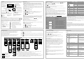
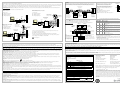
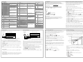
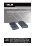
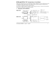
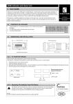
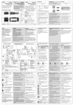
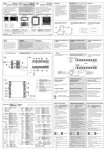
Connections Common to all Instruments 2408i Universal Indicator and Alarm Unit - Installation & Operation ENG The 2408i is a universal indicator which may be ordered or configured to measure a wide range of process inputs including temperature, volts, mV, mA, extruder melt pressure and other process variables from strain gauge or load cell transducers. It can be supplied with up to three plug in modules plus digital communications modules for Modbus, EI-Bisynch, Profibus or Devicenet protocols. The functionality is defined by an order code or it can be configured on site. This User Guide assumes that the instrument has been supplied in accordance with the order code. To configure the instrument and for features not covered here, refer to manual Part No HA027240. This and other documents can be downloaded from www.eurotherm.com. Wiring Parts Supplied and Dimensions 12.5mm (0.5 inch) 96mm (3.78 inch) 48mm (1.89inch) c e d c c d e f Also supplied 2.49Ω 1% resistor for mA inputs Snubber Display units label set 150mm (5.9 inch) f o o C F m/s cm/s x10 1x10 p.s.i bar p.s.i.x10 mmHg EUROTHERM Latching ears IP65 Sealing Gasket Panel retaining clips Sleeve Installation K l/h l/min mbar Kg/cm2 kPa mWG T/h mPas gal/min V A % %pH rev/min mV mA %RH pH mile/h Amps Wire Sizes 2 The screw terminals accept wire sizes from 0.5 to 1.5 mm (16 to 22AWG). Hinged covers prevent hands or metal making accidental contact with live wires. The rear terminal screws should be tightened to 0.4Nm (3.5lb in). Module connections 3D 38mm (1.5in) (Not to scale) 92mm (- 0.0 + 0.8) 1.77 inch (-0.0 +0.02) 3C 3B 3A 2D 2C 2B 2A 1D Module 2 Connections common to all instruments JE JD JC 2. Fit the IP65 sealing gasket behind the front bezel of the instrument 3. Insert the instrument in its sleeve through the cut-out. 4. Spring the panel retaining clips into place. Secure the instrument in position by holding it level and pushing both retaining clips forward. 5. Peel off the protective cover from the display If the panel retaining clips subsequently need removing, they can be unhooked from the side with either your fingers or a screwdriver. 1B Modules are fitted in positions 1, 2 and 3 in accordance with the ordering code. The table below shows the connections for each module and the possible functions they can perform. Note: On the wiring label the module number precedes the terminal identity letter given in the table below. For example 1A, 1B, 1C etc. Terminal Identity A B C V+ T/C - + mA R • Use the correct type of thermocouple compensating cable, preferably shielded, to extend wiring JB JA HF HE HD HC HB VI D Possible Functions Alarm or Event + - Retransmission of PV + - To power transmitters + - See wiring diagram for melt pressure transducer To power strain gauges + Thermocouple - (Analogue Input 2) (Module 3 only Order code D5) PRT + - mA (2.49Ω sense resistor) + - + - + ip1 ip2 ip3 Com ip1 ip2 ip3 Com op1 op2 op3 Com High impedance 0 2.0Vdc millivolts 0 - 10Vdc Note 1: By default the transducer supply for input 1 is installed in module position 2 The transducer supply for input 2 is installed in module position 1 • Sensor input order code Z • The resistance of the three wires must be the same V+ HA • The line resistance may cause errors if it is greater than 22Ω AC AB AA LC LB LA N Power supply connections L Line Neutral Ground V+ 100 – 240Vac Digital input 2 Linear Input V, mV and High Impedance V +80mV 0 – 10V V- Digital input 1 + 0-10V 24 20 - 29Vac/dc • Sensor input order codes F (-100 to +100mV), W (0 to 5V), G (1 to 5V), V (0 to 10V) • Order codes HA - high alarm, LA - low alarm, BD - deviation band, AD - deviation high, WD - deviation low, RT - rate of change, NW new alarm (latched alarms). • Isolated 240Vac • Relay rating: Max: 264Vac 2A resistive; min: 1V, 1mAdc to provide sufficient whetting current. • Relay shown in de-energised state Linear Input mA • Sensor input order codes Y (0 to 20mA), A (4 to 20mA) Module Ratings Relays Transmitter Supply Transducer Supply Triple Digital Input Triple Contact Closure V+ 0 – 20mA 4 – 20mA V- • For mA input connect the 2.49Ω resistor supplied across the input terminals • The resistor supplied is 1% accuracy 50ppm temperature coefficient Indicator Power Supply 1. Check order code of the indicator supplied. VH high voltage supply, 100 to 240Vac. VL low voltage supply, 24Vac/dc. OFF state: 4. For 24V the polarity is not important. ON state: <100Ω resistance OFF state output: 0 to 0.7Vdc ON state output: 12 - 13Vdc, up to 8mA Notes: 1. All module connections are isolated from the process value, earth, incoming supply and connections to other modules. 2. Digital inputs are non-isolated from the process value. 3. Digital inputs are powered by the indicator. Switching voltage and current 24Vdc/20mA. Snubbers Snubbers are used to prolong the life of relay contacts and to reduce interference when switching inductive devices such as contactors or solenoid valves. The fixed relay (terminals AA/AB/AC) is not fitted internally with a snubber and it is recommended that a snubber be fitted externally. If the relay is used to switch a device with a high impedance input, no snubber is necessary. All relay modules are fitted internally with a snubber since these are generally required to switch inductive devices. However, snubbers pass 0.6mA at 110V and 1.2mA at 230Vac, which may be sufficient to hold on high impedance loads. If this type of device is used it will be necessary to remove the snubber from the circuit. To remove the snubber from the relay module:1. Unplug the controller from its sleeve Break out 2. Remove the relay module tracks as 3. Use a screwdriver or similar tool to required to snap out the track. disconnect the snubber The view shows the tracks in a Dual Relay Output module. LA Input 1 LB Input 2 LC Common Digital input order codes are:XX - disabled. To configure refer to manual HA027240, which may be downloaded from www.eurotherm.co.uk. AC - alarm acknowledge, this has the same function as the ACK/RESET button KL - keylock, when closed all front panel buttons are disabled SR - remote setpoint select, open to select local setpoint, closed to select remote setpoint PV - process value select, open to select input 2, closed to select input 1 • Contact open >28KΩ • Contact closed <100Ω ! ! The Digital IO is not isolated from the PV input. The controller is designed to operate normally if the input sensor is connected to 240Vac, but in this case these terminals will be at this potential. J1/J2 - initiate tare correction on strain gauge input 1/2 - see section ‘Tare Correction’. J3/4 - initiate automatic calibration of strain gauge input 1/2 - see section ‘Automatic Zero and Span Calibration of a Strain Gauge Input’. Melt Pressure Transducer 2A, 264Vac resistive max. Isolated. 20mA, 24Vdc. Isolated. Configurable 5V or 10Vdc. Minimum load resistance 300Ω. OFF state: -3 to 5Vdc. ON state: 10.8 to 30Vdc, at 2 to 8mA. Powered by controller. Switching current and voltage 24Vdc/20mA nominal >28KΩ resistance Digital inputs 1 and 2 may be ordered unconfigured or pre-configured as defined by the order codes listed below. • mV range +40mV or +80mV • A high line resistance for voltage inputs may cause measurement errors 24 Plug in Modules The PDS input, digital communications and modules 1, 2 and 3 are all plug in units Triple Digital Output AC • High level range 0 – 10V Low voltage supply mV/V - AB Digital I/O For 2-wire this is a local link V- R = 2.49Ω Alarms or events 2nd Analogue Input Triple contact input. Order code TK Triple digital input. Order code TL Triple digital output. Order code TP - 10/09 Plug in I/O Module Connections Relay; changeover Order code R4 Dual relay (normally open) Order code RR DC retransmission Order code D6 Transmitter supply Order code MS (24V) Strain Gauge Transducer supply (see note 1 below) Order code G3 (5V), G5 (10V) • Sensor input order codes J, K, T, L, N, R, S, B, P, C, D, E, 1, 2, 3, 4, 5, 6, 7, 8. RTD Input 1A CN25818 Module Type V- + Comms Module Pt100 To Remove the Instrument from its Sleeve Turn off power to the instrument and ease the latching ears c outwards and pull the instrument forward. When plugging back in ensure that the latching ears click into place to maintain the IP65 sealing. V+ Module 1 Relay Output 1 10mm (0.4in) 1C Sensor Inputs V- • Order codes FH - high alarm, FL - low alarm, DB - deviation band, DH - deviation high, DL - deviation low, RA - rate of change (nonlatched alarms). AA Thermocouple or Pyrometer Input VI PDS Input Module JF This relay may be ordered pre-configured as defined by the order codes listed below. • Order code RF. The relay is fitted but not configured. To configure refer to manual HA027240, which may be downloaded from www.eurotherm.co.uk. • It is not recommended to connect two or more instruments to one thermocouple Module 3 Communications connections 45mm (- 0.0 + 0.6) 3.62 inch (-0.0 +0.03) 1.Run input wires separate from power cables 2.When shielded cable is used, it should be grounded at one point only 3.Any external components (such as zener barriers, etc) connected between sensor and input terminals may cause errors in measurement due to excessive and/or unbalanced line resistance or possible leakage currents 4.This input is not isolated from digital I/O A and digital I/O B Instrument Terminals Recommended Minimum Spacing 1. Cut out the panel to the size shown. HA030587/1 The labels on the sides of the instrument identify the ordering code, the serial number and the wiring connections. Check these to ensure that the product is supplied and configured correctly for your application. Please read ‘Safety and EMC Information’ before proceeding. PV Input (Measuring Input) Built in Relay (AA) Ensure that you have the correct supply for your indicator 2. Use copper conductors only. 3. The power supply input is not fuse protected. This should be provided externally. If the indicator is ordered with option MP it is supplied to measure melt pressure, typically in an extruder application. A Transducer Power Supply module is required in module positions 1 or 2. The diagram shows the module fitted in position 2. If input 2 is used in module position 3, the transducer output can be connected to terminals 3C (+) and 3D (-). * Calibration resistor (if fitted) A * C Safety requirements for permanently connected equipment state: D • A switch or circuit breaker shall be included in the building installation B • It shall be in close proximity to the equipment and within easy reach of the operator • It shall be marked as the disconnecting device for the equipment. Note: a single switch or circuit breaker can drive more than one instrument. L Line 24 N Neutral 24 Ground - + 3D 3C 3B 3A 2D 2C 2B 2A 1D 1C 1B 1A 24Vac or dc Ground • High voltage supply: 100 to 240Vac, -15%, +10%, 48/62 Hz. • Low voltage supply: 24Vac/dc, -15%, +10%. • Recommended external fuse ratings are as follows:For 24 V ac/dc, fuse type: T rated 2A 250V For 100-240Vac, fuse type: T rated 2A 250V. Transducer supply 1 JF JE JD JC JB JA HF HE HD HC HB HA PV input 1 V- V+ VI AC AB AA LC LB LA Relay output 1 Note: To minimise pick up of noise, it is recommended that screened cables are used for transducer power supply connections Operation Access Levels To Adjust Alarm Setpoints Switch on the indicator. After a 3 second self-test sequence, you will see the display shown below. It is called the HOME display Operator buttons The default is actual Increase a value temperature or 20 process value (PV). AL1 AL2 AL3 AL4 Decrease a value (see ‘HOME Display Select a parameter for other Options’ possibilities) Select parameter list Alarm 1 headings. See following Alarm 2 sections for more details. Alarm ACK/ Alarm 3 Beacons RESET Press to acknowledge alarms Alarm 4 There are four access levels: • Operator - parameters defined in Edit Level can be viewed and adjusted. • Full - all parameters relevant to a particular configuration are visible. All alterable parameters may be adjusted. Generally used to commission the controller. • Edit - used to set up the parameters that you want an operator to be able to see and adjust when in Operator levels 1 and 2. • Configuration - used to set up the fundamental characteristics of the controller. Access to, Full, Edit and Configuration levels is protected by security codes. For Full and Edit the code is set to ‘1’ when the controller is shipped from the factory. For Configuration refer to manual HA027240. If DSP.b is set up as AL.SP (see Home Display Options), press To View the Display Units To Return to the HOME Display Momentarily press or . The temperature units for thermocouple and RTD inputs, are flashed in the display for 0.5 second as follows: Press and together to return to the HOME display OR Do not press any button for 45 seconds. This time is reduced to 10 seconds if an alarm is being indicated. * C Celsius * F Fahrenheit * K Kelvin Note: For linear inputs no units are displayed. To Select an Access Level Press to select dsp.f (front) or dsp.b (back). Press option or to select the t to select code. Default 1. 4. Press to select goto 5. Press or to select FuLL or edit. Edit level is used to set which parameters you can view and adjust in Operator level. It also gives access to the ‘Promote’ feature, which allows you to select and add (‘Promote’) up to twelve parameters into the HOME display list, thereby giving simple access to commonly used parameters. Having selected the required parameter, use Operator levels 1 and 2. Each parameter can be set to: or to set its availability in ALtr - Makes a parameter alterable in Operator levels 1 and 2. PrO - Promotes a parameter into the Home display list. rEAd - A parameter, or list header, is read-only (it can be viewed but not altered). = Only alarm messages will be shown = Setpoint for deviation alarms = Remote setpoint for deviation alarms = Displays the maximum value on input 1 = Displays the minimum value on input 1 = Process value = Alarm 1 setpoint = Linearised input 1 = Linearised input 2 Navigation Diagram 2. Press Edit Level or temperature (process value). This is shown on the ‘front’ display. If either is pressed the display changes to the ‘back’ display for a period of two seconds. Both the front and back displays can be set up in FuLL access level to show different parameters as listed below. This facility is useful, for example, on alarm indicators, where it may be necessary to have quick access to both process value and alarm setpoint. None sp rm.SP PV.Hi PV.Lo PV aL.sp Li L2 to select accs List. 3. Press or to enter the security code. pass is displayed if the code is correct or the display will remain at ‘code’ if the password is incorrect Home Display Options When shipped from the factory the HOME display will, by default, show the measured To set up the front and back displays:From the HOME display:- 1. Press HIdE - Hides a parameter, or list header. To Return to Operator Level 1. Press to select accs List. 2. Press to select code and again to select goto 3. Press or to select Oper. Note: in ‘Edit’ level, the controller will automatically return to operator level if no button is pressed for 45 seconds. Summary The diagram below shows typical parameters available in Full access level. In practice the parameters that appear will depend on the configuration of the indicator. Further details may be found in the Engineering Handbook HA027240. Use the following lists to adjust: Front and back displays Alarm setpoints Setpoints and setpoint limits Input filter time constants and offsets User calibration Communications address 1. Press to step across the list headings. 2. Press to step down the parameters within a particular list. You will eventually return to the list heading. 3. Press to view the value of a selected parameter. Keep pressing to decrease the value. 4. Press to view the value of a selected parameter. Keep pressing to increase the value. the alarm setpoint. Press Display or or to display again to change the value. If not, select FuLL access level, then:Press until the Alarm List (AL) is shown. Press to select the alarm indicated by the mnemonic in the table below. Press or to change the alarm setpoint. Alarm Indication Note: the type of alarm is set up in Configuration level as described in handbook HA027240, which may be downloaded from www.eurotherm.co.uk. Alarm type Input Source Alarm description and function First character 1--2--3--4--Last three characters Full Scale -FSL Low -FL1 -FL2 Alarm 1 is active Alarm 2 is active Alarm 3 is active Alarm 4 is active Main PV PV 1 PV 2 PV is below the low alarm setting on the main PV PV is below the low alarm setting on PV 1 PV is below the low alarm setting on PV 2 -FSH -FH1 -FH2 Full Scale High Main PV PV 1 PV 2 PV is above the high alarm setting on the main PV PV is above the high alarm setting on PV 1 PV is above the high alarm setting on PV 2 -dLo -dL1 -dL2 Deviation Low Main PV PV 1 PV 2 PV is below the low deviation setting on main PV PV is below the low deviation setting on PV1 PV is below the low deviation setting on PV2 -dHi -dH1 -dH2 Deviation high Main PV PV 1 PV 2 PV is above the high deviation setting on main PV PV is above the high deviation setting on PV1 PV is above the high deviation setting on PV2 20 Alarm List Setpoint List AL X2 Input List SP ip Calibration List(s) (5) CAL1 (5) CAL2 Communications List (4) cmS Information List inFo Access List ACCS X2 DsP.F DsP.b C.id (1) L-r (2) FiLt HY 1 rm.SP (2) int.t CAL.P CAL.P 1dEL rm.tr OFS.1 See the section ‘User See the section ‘User mV.1 Calibration’ Calibration’ and handbook HA027240 for further information. and handbook HA027240 for further information. 1--- The above parameters are repeated if alarms 2, 3 and 4 are configured. SP (2) (6) SP 1 (2) CJC.1 (6) Sp 2 (2) Li.1 SP L in.aL inH.t Parameters are only displayed when the option has been configured Parameters are hidden by default. See ‘Edit Level’ to reveal PV.SL tare tare Addr Log.L CodE Log.H Goto LoG.A LoG.t Log.u rES.L SP H (6) SP1L (6) Sp1H (6) SP2L (6) SP2H Notes: (1) In place of dashes the last three characters indicate the alarm type. See ‘Parameter Tables’. Alarm parameters only appear if the alarm has been configured. (2) Additional parameters appear if Process Value 2 is configured in module 3. (3) These parameters only appear when the displayed value is derived from process values 1 and 2. (4) The communications list only appears if digital communications has been configured. (5) These parameters only appear if the instrument is configured for strain gauge, load cell, external reference or manual calibration. CAL2 only appears if module 3 is fitted and configured for Process Value 2. (6). Only shown if a DC Input module is fitted in position 3 Main PV -dv1 PV 1 -dv2 PV 2 PV is above or below the high and low deviation setting on main PV PV is above or below the high and low deviation setting on PV1 PV is above or below the high and low deviation setting on PV2 PV is changing faster than the rate-of change alarm setting in minutes for main input. PV is changing faster than the rate-of change alarm setting in seconds for main input. PV is changing faster than the rate-of change alarm setting in minutes for input 1. PV is changing faster than the rate-of change alarm setting in seconds for input 1. PV is changing faster than the rate-of change alarm setting in minutes for input 2. PV is changing faster than the rate-of change alarm setting in seconds for input 2. The setpoint is below the low alarm setting The setpoint is above the high alarm setting -rat -rt1 -rs1 -rt2 -rs2 -Lsp -Hsp Alarm type Rate of change (minutes) Rate of change (seconds) Rate of change (minutes) Rate of change (seconds) Rate of change (minutes) Rate of change (seconds) Setpoint low Setpoint high Main PV Main PV Input 1 Input 1 Input 2 Input 2 Main PV Main PV If other messages are flashed, see ‘Diagnostic Alarms’ Notes: 1. If the process value flashes but no other alarm message is displayed, this indicates that the input value is out of range. 2. Deviation Alarms. The master setpoint used for deviation alarms is normally derived as a remote input from another device - for example, a temperature controller. The master setpoint can also be internally set within the controller - in this case called the local setpoint value. 3. Rate of change alarms may be detected as a positive rate of change or as a negative rate of change. Set the alarm setpoint + or - respectively. Alarm Relay Output Any combination of the alarms shown in the table above can operate a particular output (usually the built in relay AA but output modules may also be configured to operate if an alarm occurs). These would normally provide plant safety interlocks or external audio/visual indication. Alarms can be assigned to a particular output in configuration level, or they are supplied pre-configured in accordance with the ordering code. To Acknowledge An Alarm Diagnostic Alarms An alarm can be acknowledged in one of three ways:- In addition to the process alarms given in the previous column, the following alarms may also appear. These warn that a fault exists, either within the indicator or in the connected devices. 1. Press the ACK/RESET button. (If this does not work it may have been disabled when the indicator was configured). 2. Press and together. 3. If a digital input has been supplied (order code AC) for alarm acknowledge, momentarily activate this input. The action, which now takes place, will depend on the type of latching, which has been configured. HOME List Alarm description and function -ras An alarm is shown when the process conditions exceed a pre-set level (setpoint). It will be displayed as follows:1. The relevant alarm beacon will flash 2. A four character alarm message will be shown as a double repeating flash in the main display. This message specifies the alarm number (first character) and the type of alarm (next three characters) as shown in the table below. The message is flashed in addition to the ‘front’ displayed value. If more than one alarm is present, the relevant beacon illuminates and further messages are flashed in the main display. The alarm indication will continue as long as the alarm condition is present and is not acknowledged. Display Input Source Last three characters Deviation band -dev Non Latched Alarms Alarm condition present when the alarm is acknowledged, the double repeating flash of the alarm message will be replaced by a single repeating flash and the alarm beacon will be lit continuously. This state will continue for as long as the alarm condition remains. When the alarm condition disappears all indication also disappears. If a relay has been attached to the alarm output, it will operate when the alarm condition occurs and remain in the operated condition until the alarm is acknowledged AND the alarm condition is no longer present. If the alarm condition disappears before it is acknowledged the alarm indication disappears as soon as the condition disappears. Latched Alarms The indicator may have been configured for Automatic or Manual reset. The action which occurs when the acknowledge button is pressed is described below:Automatic. The alarm continues to be active until both the alarm condition is removed AND the alarm is acknowledged. The acknowledgement can occur BEFORE the alarm condition is removed. Manual The alarm continues to be active until both the alarm condition is removed AND the alarm is acknowledged. The acknowledgement can only occur AFTER the alarm condition is removed. Alarm What it means What to do about it S.br Sensor break. Open circuit input on whichever input is being used as the PV Check the sensor or the connections between sensor and indicator for open circuit. EE.Er Electrically Erasable Memory Error: The value of an operator or configuration parameter has been corrupted. This fault will automatically select configuration level. Check all configuration parameters before returning to operator level. Once in operator level, check all operator parameters before resuming normal operation. If the fault persists or occurs frequently, return the unit for repair. Err1 Error 1: ROM self-test fail Return the indicator for repair Err2 Error 2: RAM self-test fail Return the indicator for repair Err3 Error 3: Watchdog fail Return the indicator for repair Err4 Error 4: Keyboard failure. Stuck button, or a button was pressed during power up. Switch the power off and then on without touching any of the indicator buttons. If the error continues return the unit for repair. Err5 Error 5: Input circuit failure Return the unit for repair Hw.Er Hardware error Indication that a module is of the wrong type, missing, faulty or a new module has been fitted. Check that the correct modules are fitted. Go to configuration mode and set up the required parameter(s). See handbook HA027240 for further information. Pwr.F Power failure: The line voltage is too low Check that the supply is within rated limits rmt.F Remote input fail Connect an input device (eg. transducer, thermocouple, mA source) to input 2 Digital Communications Connections Profibus PDS Communications protocols may be Modbus or EIBisynch. Instruments supplied with model numbers 2408i/AP and digital comms option PB are fitted with Profibus communications modules in the H slot. A description of Profibus is given in the Profibus Communications Handbook Part No HA026290 which can be downloaded from www.eurotherm.co.uk. PDS (Pulse Density Signaling) is a proprietary technique developed for bi-directional communication over a single pair of wires. PDS can be used to digitally transmit the setpoint from a 2404/08 master controller (for example) to a number of 2408i slaves - see diagram. Ordering codes:M6 - Module fitted but not configured RS - Setpoint input configured The PDS module can only be fitted in position J. Note:- In order to reduce the effects of RF interference the transmission line should be grounded at both ends of the screened cable. However, if such a course is taken care must be taken to ensure that differences in the earth potentials do not allow circulating currents to flow as these can induce common mode signals in the data lines. Where doubt exists it is recommended that the Screen (shield) be grounded at only one section of the network as shown in all of the following diagrams. A further description of Modbus and EIBisynch communications is given in 2000 series Communications Handbook, Part No. HA026230, which can be downloaded from www.eurotherm.co.uk. • Digital communications modules are isolated 240Vac CATII EIA232 Connections EIA422/EIA485 5-Wire Connections • Order codes:A2 - Fitted unconfgured AM - Modbus protocol AE - EI-Bisynch protocol • Order codes:F2 - fitted unconfgured FM - Modbus protocol FE - EI-Bisynch protocol HA Screen Tx Rx EIA232/EIA422 communications converter Com HE Rx HF Tx Screen Com Tx Local Ground Rx EIA485 3-Wire Connections EIA232/EIA 485 communications converter HA 390Ω Tx(B) Tx (B) 390Ω 220Ω Rx(A) Rx (A) 220Ω 390Ω Digital ground Node HF HE HD Profibus master 2408i slave 1 Devices should be daisy chained one to the next Node TxA Com TxB HC Rx- Rx Com HD Com Tx RxA HE Tx+ HF Tx- HC Com Com HD Com Tx Com Rx RxA HE Rx (A+) Tx RxB TxA HF Tx (B-) TxB Local Ground Rx The KD485 communications converter is recommended for interfacing to EIA 485. This unit is also used to buffer an EIA 485 network when it is required to communicate with more than 32 instruments on the same bus, and may also be used to bridge 3-wire EIA485 to 5-wire EIA 422. = Twisted pairs 2408i #2 JE JF Indicator CAN Terminal Label HA V+ HF HB HD HA HC HE HF HB HD HA HC HE Further Devices → HC 220Ω termination resistor * The use of bootlace ferrules may be an aid to wiring where two wires are to be connected to the same terminal JF This table shows standard cable connections for Devicenet. HD Drop Line Drop Line HB JE JF Terminating resistors on first and last devices HB VCAN-L Shield CAN-H V+ 2404/08 JE Node HF HE HD 2408i slave 2 Node ← Further Devices HA Screen Digital ground Indicator Terminals HD B (Rx/Tx +ve) HE A (Rx/Tx -ve) HF Dig Grnd Instruments with digital comms option code DN are fitted with Devicenet communications. Further information is available in the DeviceNet® Communications Handbook Part No HA027506 which can be downloaded from www.eurotherm.co.uk. 2408i_1 2408i_2 Local Ground Daisy Chain to further instruments * Single ground DeviceNet® Wiring Rx+ HB RxB 220Ω termination resistor on last controller in the line • Order codes:Y2 - Fitted unconfigured YM - Modbus protocol YE - EI Bisynch protocol Daisy Chain to further instruments * HB HD VP (+5Vdc) 390Ω 220Ω termination resistor on last controller in the line HC Com Shielded twisted pair cables VP (+5Vdc) 2408i #1 HE * * Note: The DeviceNet® network is powered by an external independent 24V supply which is separate from the internal powering of the individual indicators. Gnd Drop Line V- V+ DeviceNet Power Supply 24Vdc (+/- 1%) 250mV p-p Ripple max 220Ω termination resistor MASTER DeviceNet Trunk Cable HF * 121Ω termination resistor at the end of the line (may be already fitted internally in the master or the last unit. Do not fit an external terminating resistor if this is the case). Wire Description Colour Red DeviceNet® network power positive terminal. Connect the red wire of the DeviceNet® cable here. If the DeviceNet® network does not supply the power, connect to the positive terminal of an external 24 Vdc power supply. CAN_H White DeviceNet® CAN_H data bus terminal. Connect the white wire of the DeviceNet® cable here. SHIELD None Shield/Drain wire connection. Connect the DeviceNet ®cable shield here. To prevent ground loops, the DeviceNet® network should be grounded in only one location. CAN_L Blue DeviceNet® CAN_L data bus terminal. Connect the blue wire of the DeviceNet® cable here. VBlack DeviceNet® network power negative terminal. Connect the black wire of the DeviceNet cable here. If the DeviceNet® network does not supply the power, connect to the negative terminal of an external 24 Vdc power supply. Connect to instrument earth Note: Power taps are recommended to connect the DC power supply to the DeviceNet® trunk line. Power taps include: • A Schottky Diode to connect the power supply V+ and allows for multiple power supplies to be connected. • Two fuses or circuit breakers to protect the bus from excessive current which could damage the cable and connectors. • The earth connection, HF, should be connected to the main supply earth terminal. Safety and EMC Information Over Temperature Protection. This instrument is intended for industrial temperature and process control applications within the requirements of the European Directives on Safety and EMC. The information contained in this manual is subject to change without notice. While every effort has been made to ensure the accuracy of the information, your supplier shall not be held liable for errors contained herein. A closed loop temperature control system should be provided with an independent over-temperature protection unit to prevent overheating of the process under fault conditions. The 2408i could be used in this role. It must have an independent temperature sensor and isolating contactor. ! The safety and EMC protection can be seriously impaired if the unit is not used in the manner specified. The installer must ensure the safety and EMC of the installation. Safety. This instrument complies with the European Low Voltage Directive 73/23/EEC, by the application of the safety standard EN 61010. Unpacking and storage. If on receipt, the packaging or unit is damaged, do not install but contact your supplier. If being stored before use, protect from humidity and dust in an ambient temperature range of -30oC to +75oC. Electrostatic discharge precautions. Always observe all electrostatic precautions before handling the unit. Service and repair. This instrument has no user serviceable parts. Contact your supplier for repair. Cleaning. Isopropyl alcohol may be used to clean labels. Do not use water or water based products. A mild soap solution may be used to clean other exterior surfaces. Electromagnetic compatibility. This instrument conforms with the essential protection requirements of the EMC Directive 89/336/EEC, by the application of a Technical Construction File. It satisfies the general requirements of the industrial environment defined in EN 61326. Caution: Charged capacitors. Before removing an instrument from its sleeve, disconnect the supply and wait at least two minutes to allow capacitors to discharge. Avoid touching the exposed electronics of an instrument when withdrawing it from the sleeve. Safety Symbols. Symbols used on the instrument have the following meaning: ! Caution, refer to accompanying documents) Protective Conductor Terminal Installation Category and Pollution Degree. This unit has been designed to conform to BSEN61010 installation category II and pollution degree 2, defined as follows:Installation Category II (CAT II). The rated impulse voltage for equipment on nominal 230V supply is 2500V. Pollution Degree 2. Normally only non conductive pollution occurs. However, a temporary conductivity caused by condensation must be expected. Personnel. Installation must only be carried out by suitably qualified personnel Enclosure of Live Parts. To prevent hands or metal tools touching parts that may be electrically live, the controller must be installed in an enclosure. Caution: Live sensors. The controller is designed to operate if the temperature sensor is connected directly to an electrical heating element. However, you must ensure that service personnel do not touch connections to these inputs while they are live. With a live sensor, all cables, connectors and switches for connecting the sensor must be mains rated for use in 240Vac CATII. Wiring. It is important to connect the unit in accordance with the data in this sheet ensuring that the protective earth connection is ALWAYS fitted first and disconnected last. Wiring must comply with all local wiring regulations, i.e. UK, the latest IEE wiring regulations, (BS7671), and USA, NEC Class 1 wiring methods. ! Do not connect AC supply to low voltage sensor input or low level inputs and outputs. Voltage rating. The maximum continuous voltage applied between any of the following terminals must not exceed 240Vac: relay output to logic, dc or sensor connections; any connection to ground. The controller must not be wired to a three phase supply with an unearthed star connection. Under fault conditions such a supply could rise above 240Vac with respect to ground and the product would not be safe. Conductive pollution. Electrically conductive pollution i.e. carbon dust, MUST be excluded from the enclosure in which the controller is installed. To secure a suitable atmosphere in conditions of conductive pollution, fit an air filter to the air intake of the enclosure. Where condensation is likely, include a thermostatically controlled heater in the enclosure. Grounding of the temperature sensor shield. In some installations it is common practice to replace the temperature sensor while the controller is still powered up. Under these conditions, as additional protection against electric shock, we recommend that the shield of the temperature sensor is grounded. Do not rely on grounding through the framework of the machine. Note: Alarm relays within the temperature controller will not give protection under all failure conditions. Installation Requirements for EMC. To comply with European EMC directive certain installation precautions are necessary:• General guidance. Refer to EMC Installation Guide, Part no. HA025464. • Relay outputs. It may be necessary to fit a suitable filter to suppress conducted emissions. Filter requirements depend on the type of load. Typical applications may use Schaffner FN321 or FN612. • Table top installation. If using a standard power socket, compliance with commercial and light industrial emissions standard is usually required. To comply with conducted emissions standard, a suitable mains filter must be installed, such as Schaffner FN321 or FN612. Restriction of Hazardous Substances (RoHS) Product group Manufacturing Address 2400 Table listing restricted substances Chinese 限制使用材料一览表 产品 2400 铅 X O X X 印刷线路板组件 附属物 显示器 模块 O X 汞 O O O O 镉 O O O X 有毒有害物质或元素 六价铬 O O O O 多溴联苯 O O O O 多溴二苯醚 O O O O 表示该有毒有害物质在该部件所有均质材料中的含量均在SJ/T11363-2006 标准规定的限量要求以下。 表示该有毒有害物质至少在该部件的某一均质材料中的含量超出SJ/T11363-2006 标准规定的限量要求。 English Restricted Materials Table Product 2400 PCBA Enclosure Display Modules O X Pb X O X X Hg O O O O Toxic and hazardous substances and elements Cd Cr(VI) PBB O O O O O O O O O X O O PBDE O O O O Indicates that this toxic or hazardous substance contained in all of the homogeneous materials for this part is below the limit requirement in SJ/T11363-2006. Indicates that this toxic or hazardous substance contained in at least one of the homogeneous materials used for this part is above the limit requirement in SJ/T11363-2006. Approval Name: Position: Martin Greenhalgh Quality Manager IA029470U470 (CN23172) Issue 1 Feb 07 Signature: Date: Sales and Service U.K. Worthing Eurotherm Ltd Eurotherm Ltd Faraday Close Telephone (+44) 1903 268500 Worthing Fax (+44 01903) 265982 West Sussex BN13 3PL E-mail [email protected] Telephone (+44) 1903 268500 Web www.eurotherm.co.uk E-mail [email protected] Fax (+44 01903) 265982 Invensys, Eurotherm, the Eurotherm logo, Chessell, EurothermSuite, Mini8, Eycon, Eyris and Wonderware are trademarks on Invensys plc, its subsidiaries and affiliates. All other brands may be trademarks of their respective owners. © Copyright Eurotherm LtdTM 2009 All rights are strictly reserved. No part of this document may be reproduced, modified or transmitted in any form by any means, nor may it be stored in a retrieval system other than for the purpose to act as an aid in operating the equipment to which the document relates, without the prior written permission of Eurotherm. Eurotherm pursues a policy of continuous development and product improvement. The specification in this document may, therefore, change without notice. The information in this document is given in good faith, but it is intended for guidance only. Eurotherm will accept no responsibility for any loses arising from errors in this document. Parameter Tables User Calibration dSP.F Home list Measured value HOME display front. FiLt Input 1/2 filter type. dSP.b HOME display back FLt2 See HA027240 for details. C.id Customer defined identity number 0-9999 int.t Input 1/2 filter time constant Home ip See section ‘ Home Display Options’ AL 1--- Alarm List Alarm 1 setpoint 2--- Alarm 2 setpoint 3--- Alarm 3 setpoint 4--- Alarm 4 setpoint HY 1 Alarm 1 Hysteresis HY 2 Alarm 2 Hysteresis HY 3 Alarm 3 Hysteresis HY 4 Alarm 4 Hysteresis 1dEL Alarm 1 delay Used to ignore transient alarms. 2dEL Alarm 2 delay 3dEL Alarm 3 delay Alarms must be true for the delay time before they become active. 4dEL Alarm 4 delay in.aL Inhibit alarm timer In place of dashes, the last three letters indicate the alarm type as shown in Alarm Indication above. Note: If the alarm is disabled the parameter will not appear in this list. Prevents relay ‘chatter’ by setting a difference between the relay ON and OFF points. Used to inhibit alarms for a set period after power up and when a digital input is closed Used to set the alarm inhibit time inH.t Time alarm inhibited SP Setpoint list L- r Remote setpoint enable rm.SP Remote master setpoint (for deviation alarms) SP 1 Local master setpoint value for deviation alarms input 1 Local master setpoint value for deviation alarms input 2 SP 2 rm.tr Loc - Local Remote setpoint track. Only shown if remote SP is configured SP Setpoint for PV alarms SP L PV Alarm Setpoint low limit SP H PV Alarm Setpoint high limit rmt - Remote OFF - Local SP does not track remote SP Trac - Local SP tracks remote SP These are repeated for Input 1 and 2 alarms as SP1.L, SP1.H, SP2.L, SP2.H Code Oper Operator level Appears if filter type = Int Used to reduce process value flicker FuLL Full access level Edit To hide, promote or make read only parameters in Opertor levels Input 1 filter step band Appears if filter type = Step Used to reduce process flicker on weigh scale inputs OFS1 OFS.2 mV.1 mV.2 Calibration offset - input 1/2 Input 2 uses module 3 CJC.1 CJC.2 Input 1/2 Cold junction compensation temperature measured at the rear terminals Li.1 Li.2 Input 1 Linearised value Input 2 Linearised value (module 3) PV.SL Shows the currently selected PV input. Input 1/2 mV measured at the rear terminals See section ‘Access Levels’. Conf Configuration level CAL.P Calibration level Calibration Password The following parameters are shown if the correct calibration password is entered. By default CAL.P = 3. Ip.1 - Input 1 selected Ip.2 - Input 2 selected Both - Input 1 and 2 selected Tare Performs automatic ‘Tare’ correction, on input 1 CAL.P Calibration password (see following sections) cms Digital Communications List Addr Communications address info Information List Log.L Logged Minimum Process Value LoG.H Logged Maximum Process Value Log.A Logged Average Process Value LoG.t Time process value is above threshold level Log.v rES.L CAL See the section ‘User Calibration’ and handbook HA027240 for further information. tArE.v 1 to 99 EIBisynch 1 to 254 Modbus SG Fact = select factory calibration USEr = Select User Calibration (see next panel) Tare value. This sets a fixed offset on the tare value. It may be used, for example, if containers of different weights are placed on a pallet of known weight. inP.L ScL.L Transducer low scale Process value threshold for timer log Inp.H Transducer high scale Logging reset ScL.H Scale high point Indicator under Calibration - + 3D 3C 3B 3A 2D 2C 2B 2A 1D 1C 1B 1A Transducer supply 1 3D 3C 3B 3A 2D 2C 2B 2A 1D 1C 1B 1A Transducer supply 1 JF JE JD JC JB JA HF HE HD HC HB HA JF JE JD JC JB JA HF HE HD HC HB HA PV input 1 PV input 1 V- V+ VI AC AB AA LC LB LA Load Cell V- V+ VI AC AB AA LC LB LA Reference transducer Measurement transducer This diagram shows connections to input 1 the main input If Input 2 is used in module position 3, the transducer output can be connected to terminals 3C (+) and 3D (-) Select User calibration as described in paragraphs 1 to 4 above, then:until you reach ScL.L (scaling low), and enter the minimum display 5. Press reading when the transducer has its lowest weight (0 if there is no weight on the transducer). 6. Press to show Pnt.L (cal point 1) and set this to on. The indicator will show busy while calibrating. 7. Repeat for Pnt.H - the maximum display reading when the transducer has its highest weight. The indicator will flash done when calibration is complete. If it fails tdr.F is displayed. Note: It is possible to configure external contact inputs to activate Pnt.L and Pnt.H. In this case the process calibration points are not entered ahead of performing the calibration. The input may be set to any value and, when the system is stable, a reading is taken from the reference measurement device and entered into the indicator. The indicator stores both this new target value and the actual reading taken from its input. The process is repeated at a different value, with the indicator storing both the new target value and the reading taken from its input. Select User calibration as described in paragraphs 1 to 4 above then:to show Pnt.L (cal point 1) and set this to on. The indicator will 5. Press alternate between adj (adjust) and the value shown in the display. 6. Press Factory Calibration It is always possible to return to the factory calibration by setting CAL to fact. or Fixed offset OFS.1 or OFS.2 Input Two Point Offset Alternatively, a two point offset may be applied for each input which privides a different offset at the lower and higher ends of the range. This requires access to Configuration Level and is described in issue 2 of Handbook HA027240 which can be downloaded from www.eurotherm.co.uk. to enter the value indicated by the reference instrument. 7. Repeat for pnt.H - the maximum display reading 2. Press until you reach the CAL1 3. Press using until you reach the CaL.p parameter and enter the calibration password or , - default value 3. 4. Press to show CAL and set this to User using or 5. Press until you reach inp.L (transducer low scale). For a transducer range 0 to 10,000psi set this to 0. 6. Press until you reach ScL.L (scaling low), and enter the scale low value normally 0 (0% of transducer range). until you reach inpH (transducer high scale). For a transducer range 0 to 7. Press 10,000psi set this to 10000. 8. Press until you reach ScL.H (transducer high scaling point), and enter the scale high value - normally 80 (80% of transducer range). 9. Press to show Pnt.L (start low point calibration) and set this to on. The indicator will show busy while it automatically calibrates the transducer, then return to Pnt.L. If the calibration fails tdr.F is displayed. The above procedure may be repeated for input 2 using the list CAL.2. Alternatively, it is possible to order the indicator with a digital input configured to initiate automatic calibration of input 1 or input 2 (digital input code J3 or J4 respectively). In this case making the digital input will have the same effect as paragraph 9 above and will automatically calibrate the strain gauge transducer. Scale low point Comparison Calibration This calibrates the indicator against a separate reference instrument. Reference measurement device Factory calibration If User Calibration is selected:- These values are logged by the indicator from switch on. To reset switch the indicator supply off and on again or scroll to rESL and select YES Start low point calibration If Input 2 is used in module position 3, the transducer output can be connected to terminals 3C (+) and 3D (-) Span calibration is performed by applying either: 1. A calibration resistor contained within the transducer assembly OR 2. A calibration resistor fitted within the transducer power supply module. The value of this resistor is 30K1Ω. Calibration Procedure (process input 1). Specific gravity multiplier. For materials with specific gravity different from water (1). Pnt.L This diagram shows connections to input 1 - the main input Calibration Offset This allows you to apply a single offset to the input to compensate for sensor and other system errors. You can apply a simple fixed offset, independently for each input, over the whole display range using the parameter OFS.1 or OFS.2 in the ip list. Automatic Zero and Span Calibration of a Melt Pressure Transducer The indicator can accept up to two transducer inputs. Transducer power supply modules are used to provide an excitation voltage of either 5 or 10Vdc. A melt pressure tranducer is normally calibrated at 0% and 80% of its full range. This is set using parameters ScL.L and ScL.H as described below. Wire the transducer as shown overleaf. 1. Remove any load from the transducer to establish a zero reference. User Calibration List - Input 1 (CAL2 is shown if module 3 is configured for DC input - + User Calibration is designed to provide the facility for day to day adjustments by the operator. It includes input offset; tare correction; transducer, load cell and comparison adjustments. These are briefly described below but for a full description please refer to manual HA027240 which can be downloaded from www.eurotherm.co.uk. Displayed value CAL1 Indicator under Calibration Load Cell Access List Off - No filter Int - Integrating filter Step - Step StP.b Load Cell Calibration A load cell with V, mV or mA output may be connected to Input 1 or Input 2 as shown below:Reference Weight ACCS Input list Tare Correction or Auto-Tare Tare Value or Display Zero This is used, for example, when it is required to weigh the contents of a container but not the container itself. Alternatively, it can be used to set a fixed offset on an initial measured value. By default Tare correction is available in FuLL access level, and is described in the procedure below:- The parameter Tare Value (tArE.v) sets a fixed offset on the tare measurement. This may be used, for example, if containers of different weights are placed on a pallet of known weight. This known weight can then be entered in tArE.v. 1. Place the empty container on the weigh cell 2. Repeatedly press 3. Press until C A L . 1 is displayed. to select tArE and press or The effect of Tare Value is to introduce a DC bias to the measurement. A Tare calibration will change the values of ‘Scale High’ ScL.L and ‘Scale Low’ ScL.H as shown in the figure below:- to select On 4. The display changes to busy as the indicator takes the measurement from the strain gauge. 5. The weight of the container will automatically be taken from the total weight and the display will return to the HOME display. New Scale High New Scaling If the calibration fails the alarm message tdr.F (transducer fail) will flash. Tare value It may be more convenient to ‘promote’ the tArE parameter to Operator level as described in the example below. In this case it will be available by pressing when in Operator level. PV at tare point Alternatively, a digital input may have been configured to provide this function via an external source such as a switch or pushbutton (digital input order codes J1 - input 1 or J2 - input 2). In this case pressing the button will have the same effect as selecting ‘On’ in 3 above. Scale Low The above procedure may be repeated for input 2 (if provided) using the list CAL.2. Example 1: To Promote TArE to Operator Level 1 Select Edit level as described in section ‘Access Levels’. • The values are accepted by scrolling away from AdJ Press to select CAL.1 • It is possible to configure external contact inputs to activate Pnt.L and Pnt.H. Press to select tArE and press or to select Pro Tare offset Scale High New Scale Low Tare offset Original Scaling Tare offset Input Low Input at autotare point Input High Having entered a Tare Value, Auto-Tare can be initiated as described in the previous column. It may be more convenient to ‘promote’ the tArE.v parameter to Operator level as when in described in the example. In this case it will be available by pressing Operator level. Example 2: To Promote Tare.v to Operator Level 1 Select FuLL level as described in section ‘Access Levels’. Indicator Calibration Calibration of inputs 1 and 2, and retransmission outputs should not be confused with User Calibration. Calibration of these functions in done in Configuration level and should not normally be necessary. They are, therefore, described in handbook HA027240. Press to select CAL.1 Press to select CAL.p and enter the calibration password (3) Select Edit level Press to select CAL.1 Press to select tare.v press or to select Pro