1
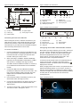
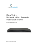
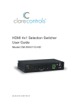
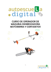
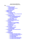
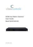
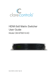
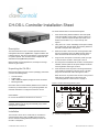
CH-OS-L Controller Installation Sheet
To mount the CH-OS-L in the structured panel:
1.
Place the mounting bracket inside the structured panel,
under the CS-iMR, ensuring that you allow at least .5 in
(1.3 cm) of clearance space at sides and bottom of the
bracket, and at least 2 in. (5.1 cm) at the top. See
Figure 1.
2.
Using four 6-20 ! 3/8 in. self-drilling screws (not included)
and a power drill, securely attach the mounting bracket to
the back of the panel box. See Figure 1.
3.
Slide the CH-OS-L device into the mounting bracket with
the rear connections facing up. Make sure the device is
flush with the bracket and fits securely. See Figure 2.
4.
Plug one end of the power cord into the power input port
on the rear of the CH-OS-L. See Figure 2, item 5.
Note: Models, and their appearance, are subject to change
without any prior notice.
5.
Run the power cord between the CH-OS-L and the panel’s
sidewall, and then place the AC power adapter under the
mounting bracket. See Figure 2, item 4.
Unpacking the CH-OS-L
6.
Insert the other end of the power cord though the bottom
of the panel box (where the hole was cut out), and then
plug it into the electrical outlet. See Figure 2, item 3.
Description
The Clare Controls CH-OS-L controller provides all device
management services to AppModules, supports all Clare user
interface services, and acts as the gateway to the ClareCloud
for system updates. The controller comes complete with the
ClareOS and all AppModules preloaded.
Remove all contents from the CH-OS-L packaging and ensure
you have the following items.
•
•
•
•
Note: Do not turn on power to the CH-OS-L until you have
made all your network device connections. See
“Connecting devices to the CH-OS-L” on page 2.
CH-OS-L device
Power supply
USB to Ethernet adapter (dongle) for RJ-45 connection
Mounting bracket
Figure 1: CH-OS-L mounting bracket in panel
Record the device’s UUID address (labeled on the bottom of
the device) on the line below. Your system programmer will
need this information to configure the CH-OS-L device.
2 in.
(5.1 cm)
UUID address: __________________________________
.5 in.
(1.3 cm)
Do not use this address for more than one account.
WARNING: Do not power on the CH-OS-L until installation is
complete. Failure to do so may result in bodily injury and/or
damage to the equipment.
(1)
.5 in.
(1.3 cm)
Installation
(1)
The CH-OS-L can be set on a rack shelf, or mounted in a
structured panel, along with a CS-iMR multi-room audio
device. Use the mounting bracket (included) to mount the
CH-OS-L in the panel.
© 04APR14 Clare Controls, Inc.
1/5
CH-OS-L mounting bracket
Doc ID 2014-04-197 • REV 04
Figure 3: CH-OS-L rear connections
Figure 2: CH-OS-L mounted in bracket
(5)
(2)
(1)
(3)
(4)
(5)
(6)
(7)
(1)
(1)
(2)
(3)
(4)
(2)
(5)
(6)
(7)
Network port
S/PDIF out port (not used)
Power input port
Figure 4: CH-OS-L front connections
(3)
(1)
(2)
(3)
RF port (not used)
USB ports
Display Output port (VGA)
HGMI port (not used)
(4)
CH-OS-L
Power plug
Electrical outlet
(4)
(5)
AC power adapter
Power plug to CH-OS-L
Connecting devices to the CH-OS-L
After mounting the CH-OS-L, make the connections to your
other devices. Figures 3 and 4 identify the ports on the rear
and front of the CH-OS-L. Refer to the documentation that
came with each of your other devices for detailed information
about connecting those devices to the CH-OS-L.
(1)
(1)
(2)
(3)
(4)
(2)
(3)
Headphone port
Microphone In
Multi-function card reader
USB ports
(4)
(5)
(6)
(7)
(5)
(6)
(7)
LEDs
Suspend button
Power button
Configuring the CH-OS-L data and audio networks
To connect the CH-OS-L:
1.
Connect a keyboard and a mouse to the USB ports, and
then connect monitor to the Display Output port. You will
need these devices to configure your data and audio
networks. See Figure 3, items 2 and 3.
2.
When connecting to a CS-BR-1 Steams Audio Bridge
(optional), use the USB cable included with the CS-BR-1
and connect it to a USB port. See Figure 3, item 2.
The USB connection enables the CS-BR-1 to encode up
to four simultaneous audio streams onto the CobraNet
network.
3.
Connect the USB end of the USB Ethernet adapter
(included) to a USB port on the rear of the CH-OS-L, and
then connect an Ethernet cable to the other end of the
adapter and to the CobraNet network switch. See
Figure 3, item 2.
4.
Use an Ethernet cable (not included) to connect to your
data network switch. See Figure 3, item 5.
5.
Connect the power adapter to the power input port, and
then plug the other end into an electrical outlet. See
Figure 3, item 7.
6.
To power on the CH-OS-L, press the power button on the
front of the CH-OS-L. See Figure 4, item 7.
2/5
Note: Before you begin configuring your CH-OS-L, ensure that
you have a monitor, keyboard, and mouse connected to your
CH-OS-L controller. You will not be able to make changes
without these peripheral devices. Be sure to connect the
monitor and turn it on before booting the CH-OS-L. This
ensures the CH-OS-L recognizes the monitor.
To ensure a secure Internet access, we recommend that you
connect your CH-OS-L controller to the Internet using a
hardwired connection. The wired Internet connection icon
displays in the menu bar.
When you apply power to the CH-OS-L, the system boots and
displays the desktop interface on your monitor, as shown in
Figure 5. Use this interface to configure the system so that the
controller can support both data and audio networks (CobraNet
for audio) and can communicate with all of the devices,
including iDevices.
Figure 5: Desktop interface
Doc ID 2014-04-197 • REV 04
To configure the CH-OS-L:
1.
2.
6.
In the Device MAC address field, click the drop-down
arrow, and then select your connection’s MAC address
and system name “eth0”. This is the main network
connected to the Internet.
7.
Click Save.
8.
Click Wired Connection 2, and then select the Edit button.
9.
In the Connection name field, enter a meaningful name,
such as “CobraNet.”
Click the Up/Down arrow icon located in the title bar to
display the drop-down list, and then select Edit
Connections.
In the Network Connections dialog, select the Wired tab.
10. Select the Connect Automatically and Available to all
users check boxes if they are not already selected.
11. In the Device MAC address field, click the drop-down
arrow and select your connection’s MAC address and
system name “eth1”. This is the Media Network.
12. Click Save.
Note: Normally, the system will show two wired
connections. If you do not have active profiles, click the
Add button and add it.
To set up the static Internet connection:
1.
Click the IPv4 Settings tab to edit your connections.
3.
Click Wired connection 1, and then click Edit to display the
Editing dialog.
2.
In the Method field, click the drop-down arrow, select
Manual from the list, and then click Add.
4.
In the Connection name field, enter a meaningful name,
such as “ClareHome.”
5.
Select the Connect Automatically and Available to all
users check boxes, if they are not already selected.
Doc ID 2014-04-197 • REV 04
3/5
3.
In the Addresses section, add the information for Address,
Netmask and Gateway fields.
Note: The field will be red while editing. When you enter a
correctly formatted IP address, it will turn green.
4.
Validate the correct DNS information for your client’s
Internet connection, and then in the DNS servers field,
enter the DNS information in the following format.
<ipaddress>comma<ipaddress>
Changing the time zone
Your ClareHome CH-OS-L controller comes preloaded with the
Ubuntu operating system and is preset to the Eastern Time
zone. If you are installing your CH-OS-L controller in a different
time zone and you wish to change the system time and date,
follow the directions below.
To change the time zone:
1.
From the desktop, click the Gear icon
in the upper-right
corner, select System Settings from the drop down menu,
and then click the Time and Date icon.
2.
Click the Time & Date tab, if it is not already selected.
3.
In the Location field, type the name of your city, or the
name of a large city in your time zone, where you are
installing the CS-OS-L.
Example:
8.8.8.8,8.8.4.4
5.
Click Save.
To set up a static CobraNet connection:
1.
In the Method field, click the drop-down arrow, select
Manual from the list, and then click Add.
As you type, the system displays a list of matching cities.
4.
2.
In the Addresses section, add the information for Address,
Netmask and Gateway fields.
3.
DNS entries are not needed for CobraNet, so leave the
DNS servers field blank.
4.
Click Save.
5.
Click Close.
6.
Reboot the CH-OS-L device by selecting the Power Gear
icon in the upper right hand corner of the screen, and then
select Restart.
7.
Notice that the system highlights the time zone on the map and
pinpoints the selected city.
Setting the time and date
The system gives you two options for setting the time and date,
Manually or Automatically from the Internet. We recommend
that you select Automatically from the Internet to sync the clock
with your Internet server clock.
To set the time and date automatically:
1.
When the system reboots, open your browser and
navigate to a site to validate Internet connectivity, such as
Yahoo, Google, etc.
Click Automatically from the Internet.
The system searches the Internet and automatically sets
the time and date for your city.
2.
4/5
Choose your city from the list.
Reboot the CH-OS-L to sync the local time setting with the
ClareHome services.
Doc ID 2014-04-197 • REV 04
Displaying the time and date in the menu bar
If you wish, you can display the time and date in the system’s
menu bar.
To display the time and date in the menu bar:
1.
Click the Clock tab to display its options.
2.
Select the boxes for the time and date format you want to
appear on the menu bar, as shown below.
Configure, test, and deploy a project
Refer to the Fusion Configuration Tool Administrator Guide
(Doc ID 069) for instructions on creating, testing, and deploying
a project. When you deploy the project from Fusion, it will
deploy to the CH-OS-L.
To test the CH-OS-L setup:
1.
Create a new project with all Gateway settings and MAC
address.
2.
Create areas for the project.
3.
Configure one device, and then create a service.
4.
Deploy the project to the Gateway and test it in the Clare
Controls App.
Specifications
Power
65 W
Dimensions (W ! H ! D)
7.5 ! 1.0 ! 5.3 in. (19.0 ! 2.5 ! 13.5 cm)
Weight
15.8 oz. (.45 kg)
Contact information
Clare Controls, Inc.
7519 Pennsylvania Ave, Suite 104
Sarasota, FL 34243
Support: 941.404.1072
Fax: 941.870.9646
http://support.clarecontrols.com
www.clarecontrols.com
Doc ID 2014-04-197 • REV 04
5/5