1
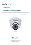
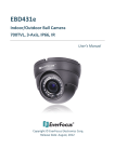
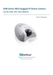
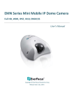
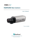
PowerVideo Plus® EverFocus Central Management Software for Networked Video Devices Management User’s Manual Copyright © EverFocus Electronics Corp. Release Date: July, 2012 Copyright 2012 EverFocus Electronics Corp. All rights reserved. No part of the contents of this manual may be reproduced or transmitted in any form or by any means without written permission of the Everfocus Electronics Corporation. EverFocus 12F, No.79, Sec. 1, Shin-Tai Wu Road, Hsi-Chih, Taipei, Taiwan TEL: +886 2 2698 2334 FAX: +886 2 2698 2380 www.everfocus.com.tw July, 2012 Contents Chapter 1 Introduction ................................................................................ 1 1.1 1.2 1.3 System Requirements ....................................................................................... 1 Installation ........................................................................................................ 2 Main Screen ...................................................................................................... 3 Chapter 2 Getting Started ............................................................................ 4 2.1 2.2 2.3 Accessing the PowerVideo Plus ........................................................................ 4 Adding a DVR, Mobile DVR or an IP Camera..................................................... 5 Configuring the User Account ........................................................................... 7 Chapter 3 Live View ..................................................................................... 9 3.1 MATRIX VIEW...................................................................................................... 10 3.2 FLOATING MATRIX ................................................................................................ 12 3.2.1 Activating Multiple Monitors .............................................................. 12 3.2.2 Configuring the Floating Matrix .......................................................... 13 DIGITAL ZOOM .................................................................................................... 15 3.3 Chapter 4 Recording ...................................................................................16 4.1 Changing the Recording Path.......................................................................... 16 Chapter 5 Playing Back ...............................................................................17 5.1 5.2 Archiving Recordings from the DVRs / Mobile DVRs to the Local Computer .. 18 Quick Search ..................................................................................................... 19 Chapter 6 Remote Playback ........................................................................20 Chapter 7 Dynamic E-Maps ........................................................................21 7.1 7.2 7.3 Activating the Dynamic E-Maps ....................................................................... 22 Creating a Group .............................................................................................. 22 Configuring the Dynamic E-Maps..................................................................... 23 Chapter 8 Recording Schedule (IP Camera) .................................................27 Chapter 9 Archiving Schedule (DVR) ...........................................................28 9.1 Changing the Recording Path of the Auto Archiving Server............................. 29 Chapter 10 Alarm Settings ..........................................................................30 10.1 Activating the Alarm Function........................................................................ 31 i 10.2 10.3 Configuring the Alarm Server ......................................................................... 32 Enabling the Alarm Function on the Main Screen ......................................... 35 Chapter 11 PTZ Control...............................................................................36 Chapter 12 Backup Utility ...........................................................................38 Chapter 13 Bandwidth Monitor ..................................................................40 ii PowerVideo Plus Chapter 1 Introduction The PowerVideo Plus is a central management system (CMS) that allows you to remotely manage EverFocus’ DVR, Mobile DVR and IP cameras connected on the LAN or WAN. Supported Models: All EverFocus branded products (few products are still in the integration process). Key Features: • • • • • • • • • • • Simultaneously access any combination of IP, analog and mobile devices Up to 10 pages of 8 x 8 Live View Matrix screens with automatic timer based page flipping (see 3.1 Matrix View) Supports unlimited number of monitors up to Microsoft Windows minimum limit (see 3.2 Floating Matrix) Manual, scheduled and event based recording Supports multiple recording folders and round-robin over-write schema PTZ controls and digital zooming Bandwidth monitor Time / Event / Smart search User access management GPS tracking Dynamic E-Maps 1.1 System Requirements Minimum Recommended OS (32 / 64-bit) Windows XP (Service Pack 3) Windows 7 CPU Intel Core 2 Duo Intel Core i3 or later RAM 2 GB 4 GB Graphic Card Intel onboard graphic cards AMD / NVIDIA DirectX 10 compliant graphic cards Ethernet 10 / 100 Base-T Ethernet 1000 Base-T Ethernet Hard Disk 50 MB for program install 500 GB or more recommended for video storage 1 PowerVideo Plus 1.2 Installation You have to download the PowerVideo Plus software and then install it in your computer. To download the PowerVideo Plus software, go to EverFocus’s website (www.everfocus.com.tw) and follow the steps below. 1. Click Download, select Software and then click PowerVideo Plus. 2. Extract the zip file to your computer. 3. Double-click Setup.exe, and follow the on-screen instructions. 2 PowerVideo Plus 1.3 Main Screen Figure 1‐2 The controls on the Main Screen: No. Name Description 1 Application Click to log out or exit the system. 2 Live View Click to modify the display of the Live View Matrixes. By default, the live view matrix is in single camera view. See 3.1 Matrix View. 3 Devices Includes the functions related to Device Management, Remote DVR Archive, Playback and Snapshot List Search. 4 GPS Click to start GPS tracking or playing back GPS data. 5 Report Click to print out the alarm report. 6 Dynamic E‐Maps Click to start the Dynamic E‐Maps function. See 7. Dynamic E‐Maps. 7 Option Click to set up the Storage Path, Recording Schedule, Archiving Schedule, User’s Privileges Management, and the Language of the user interface. You may also start the Alarm Server, Auto Archive Schedule Server, Record Schedule Server, Backup Utility and Bandwidth Monitor. 8 About Click to view the version of the PowerVideo Plus and its list of supported devices. 9 Full Screen Icon Click to view / exit full screen. 10 Device List Displays the list of DVRs, Mobile DVRs or IP cameras currently configured. 11 Display Window Displays the live view matrix. 3 PowerVideo Plus Chapter 2 Getting Started 2.1 Accessing the PowerVideo Plus Start the PowerVideo Plus software, the following login dialog box appears. Please type your user name, password and then click the Login button to enter the system. The default user name and password are admin. Figure 2-1 Note: 1. To change the language of the user interface, click Option (No.7, Figure 1-2) and click Select Language. 2. To change the username or password, click Option (No.7, Figure 1-2) and select User Management. See 2.3 Configuring the User Account. 4 PowerVideo Plus 2.2 Adding a DVR, Mobile DVR or an IP Camera You need to add a DVR, Mobile DVR or an IP camera before start using the device related features. You can automatically search for EverFocus’ devices on the network and then add them to the Device List or add EverFocus’ devices manually. To automatically search for EverFocus’ devices on the network: 1. Click the Devices button (No.3, Figure 1-2) and click Device Management. The following dialog box appears. Figure 2-2 2. Click the Auto Discover Device button . The connected devices will be listed. Figure 2-3 3. Select the desired device and click the Login button to login to the device. The system will detect the selected device automatically. Note: You can login to multiple devices having the same User / Password combination at the same time by selecting multiple devices. 5 PowerVideo Plus 4. Type a meaningful name in the Machine Name field to help you identify the device and then click to save the settings. Once all of your devices are added, click to close the Find Devices window. The device list should now contain the list of the devices just added. To manually add an EverFocus’ device: 1. Click the Add Device Wizard button in Figure 2-2. The following dialog box appears. Figure 2-4 2. Type the Device Name, IP Address, User Name and the Password of the IP device. Modify the default port if necessary. 3. Select the device type of the IP device from the Device Type drop-down list. 4. Click Next. The wizard will verify the IP device automatically. Click Finish. Figure 2-5 6 PowerVideo Plus 2.3 Configuring the User Account You can create multiple user accounts with different privileges. Click Option (No.7, Figure 1-2) and select User Management. The User Privileges dialog box appears. Figure 2-6 1. To create a group, click the Groups tab and click the Add New Group button . 2. Type a name for the new group and select the privileges for the new group. 3. Click the Save Group button to save the settings. 4. To create a new user, click the Users tab and click the Add New User button . 5. Select the Group the user belongs to and enter the User name and the password in the Password and Confirm Password fields. 6. Click the Save User button to save the settings. 7 PowerVideo Plus To change the password: 1. Click the Users tab, select a group and then type the user name and password. 2. Type a new password in the Password and Confirm Password fields. 3. Click the Save User button to save the settings. To block specific cameras from a Group: 1. Click the Device Privilege tab, select a group and select a device. The related cameras will be displayed on the Allowed list. 2. Select a camera and use the 3. Click the Save button buttons to add / remove the camera to the Blocked list. to save the settings. Figure 2-7 8 PowerVideo Plus Chapter 3 Live View You can manage the live video on the display window. Drag a camera from the Device List and drop it on the display window. Right‐click the Live View window, the tool bar appears on the upper right corner. Figure 3‐1 The Live View Tool Bar Figure 3‐2 No. Name Description 1 Unpin Unpin the live view from the Display Window. Click the button again to pin back. 2 Take a Snapshot Click to take and then print a snapshot. 3 Configure Settings Click to access the Web interface of the IP device for configuration. 4 Quick Playback Play back the videos from the predefined interval. 5 Channel Channels: Switch between channels from the DVR. Sub‐stream: Click to enable / disable sub‐stream. By default, the live view is displayed in sub‐stream. 6 Close Stream Click to close the live view window. 7 Start Record Click to start / stop recording (IP camera only). 8 Stream Select a stream to display the live view (IP camera only). 9 PowerVideo Plus 3.1 Matrix View The Matrix View allows you to monitor up to 64 cameras from EverFocus’ DVR, Mobile DVR or IP cameras on the same screen. You can edit up to 10 pages of Matrix View in different matrix sizes. 1. On the Main Screen, click Live View, click Go To Page and select a page and then click. Figure 3-3 2. Click Live View, click Matrix and select a matrix size. Figure 3-4 3. Drag and drop the cameras from the Device List to the desired squares on the Display Window. 4. Click Live View and click Save Current Page to save the settings. 5. Repeat Step 1 to Step 4 to edit another page. 6. To add a certain page to the Favorites Page, on Figure 3-3, click Add to Favorites. 10 PowerVideo Plus 7. To edit the name or the interval time of a page, click Live View and click Adjust Page Timer. Click on the page name to type a name or click on the time interval to set up an interval in second. The minimum interval is 30 seconds. Figure 3-5 8. Click the Save Page button to save the settings. To use the Sequencing function, on the Main Screen, click Live View and click Enable Sequencing. The edited Matrix View pages will be displayed in sequence based on the time interval. 11 PowerVideo Plus 3.2 Floating Matrix You can use the Floating Matrix function to create more screen space to display multiple channels on multiple monitors. The number of monitor is unlimited up to Microsoft Windows minimum limit. This function is useful for TV wall control. Figure 3-6 3.2.1 Activating Multiple Monitors Use Windows Display Properties to activate multiple monitors. Here we use Windows XP for example to illustrate the steps. 1. Right-click the desktop, click Properties and click the Settings tab. The Display Properties dialog box appears. Figure 3-7 12 PowerVideo Plus 2. Click the Display list. If you do not see multiple monitors listed, check if your additional monitors are connected with the computer properly. 3. Select the primary monitor from the list, and select Use This Device as the Primary Monitor. 4. Select additional monitors from the list, and select Extend my Windows desktop onto this monitor for each monitor. 5. Click Identify. Windows XP displays a large number to identify your monitors. Drag and drop the monitor icons to match the physical arrangement of your monitors. 6. Click OK. 3.2.2 Configuring the Floating Matrix You can set up multiple Floating Matrix windows to display the matrix live view on additional monitors. Each Floating Matrix window can be set up with up to 64 channels from Everfocus’ DVR, Mobile DVR and IP cameras. You can edit up to 10 pages of Matrix View in different matrix sizes for each Floating Matrix window. Figure 3-8 13 PowerVideo Plus 1. On the Main Screen, click Live View, click Floating Matrix Window and click Add New Floating Window. The above window appears. 2. Type a name for the Floating Matrix window in the name field 3. Click . to select a page. 4. Click to select a matrix size for the selected page. 5. Drag and drop the cameras from the Device List on the Main Screen to the desired squares on the Floating Matrix Window. 6. Click the Settings button and select Save Current Page. 7. Repeat Step 3 to Step 6 to edit another page. 8. To edit the interval time of a page, click the Settings button and select Adjust Page Timer. Click on the page name to type a name or click on the time interval to set up an interval in second. The minimum interval is 30 seconds. Figure 3-9 9. Click the Save Page button to save the settings. To use the Sequencing function, click the Settings button and click Enable Sequencing. The edited Matrix View pages will be displayed in sequence based on the time interval. 14 PowerVideo Plus 3.3 Digital Zoom You can zoom in / out the camera live view through the PowerVideo Plus. On the camera live view, click the Unpin button (No.1, Figure 3-2) to unpin the camera live view from the Display window. Click the Show Digital Zoom button on the right edge of the camera live view, a separate live view window with Zoom In and Zoom Out buttons appears. Click the Zoom In / Zoom Out button to zoom in / out the camera live view. Figure 3-10 15 PowerVideo Plus Chapter 4 Recording You can record live videos from the connected IP cameras. Click the Start Record button on the Live View Tool Bar to start / stop recording the camera live view. Figure 4‐1 4.1 Changing the Recording Path By default, the live view recordings of the IP cameras are saved at C:\Program Files\Everfocus\PowerVideo Plus. Follow the steps below to change the recording path. 1. On the Main Screen, click Option and click Configure Record Storage Path. Figure 4‐2 2. Click the Record Storage Path tab, click the Add New Path button and select a storage location. The new path will be listed in the storage path list. 3. Double click on the added path to enable it as the default path. The color of the wordings will change to red to indicate the path has set up as the default path. 4. You can optionally enable Recording file (s) overwrite, if disk drive is full. 5. Click the Save button to save the settings. 16 PowerVideo Plus Chapter 5 Playing Back You can play back the recordings stored in your computer using EverFocus’ EFPlayer with enhanced features. For DVR / Mobile DVR users, you will have to archive the recordings to your computer before using the EFPlayer. Double‐click the EFPlayer icon , click the Load Files button to load the recording file and then click the Play button to play back the recording. Figure 5‐1 To turn on / off the camera view for playing back, click the number of channel button. To display the camera view to fit the screen size on the Screen Division, enable Fit Screen. To save a video image in JPG format, click the JPG button. To save a video file in AVI format, click the AVI button. To display the next / previous frame, click the Step Forward / Step Reverse button. 17 PowerVideo Plus 5.1 Archiving Recordings from the DVRs / Mobile DVRs to the Local Computer You can manually or automatically archive the recordings from the DVRs / Mobile DVRs to your local computer for playing back the recordings using EverFocus’ EFPlayer. For automatically archiving the recordings from the DVR, see Archiving Schedule (DVR) in Chapter 9. 1. To manually archive the recordings from the DVR, on the Main Screen, click Devices, click Archive and select DVR or Mobile DVR. The following dialog box appears. Note that for Mobile DVR, you need to buy license to use this feature. Figure 5-2 2. Select a device, select the desired cameras, select the time period and the stream type. Note: You can set up the date and time period by clicking on them and type the desired date and time. 3. Click Archive and then select a storage path for the recordings. The recordings will be saved in .avr format. 18 PowerVideo Plus 5.2 Quick Search Quick Search is a very useful tool for searching and playing back IP camera recordings stored in the local computer. On the Main Page, click Devices, click Playback and select IP Camera. Select the desired device, date and time, recording type and file type. Click the Search button and the desired recordings will be listed. Select a desired recording and click the Play button. Figure 5-3 19 PowerVideo Plus Chapter 6 Remote Playback You can remotely play back recordings from the DVRs / Mobile DVRs using the internal built-in player. 1. On the Main Page, click Devices, click Playback and select DVR or Mobile DVR. Figure 6-1 2. Select a device and select a search type to search for the desired recordings. Time Search: Search the recordings with a specific date, time and stream type. Event Search: Search the recordings with the selected event type: alarm or motion. Smart Search: This feature is only available on DVR devices. Smart Search allows you to search the recordings with unattended or missing objects in a period of time. Click the Show Grid button to specify multiple regions for unattended or missing objects. 3. Click the Play button to play back the desired recording. 20 PowerVideo Plus Chapter 7 Dynamic E-Maps You can configure a dynamic E-Map alert to lay out the locations of triggered cameras and alarms within a floor plan. When a motion, video loss or input trigger is detected, the color of the camera icon will turn red or yellow for alert (red for video loss and yellow for triggered cameras and alarms). You can also right-click the camera icon and select View Camera to see its live view. By doing so, the camera icon will turn green. Figure 7-1 You have to enable the Alarm Server for using the Dynamic E-Maps function. On the Main Screen, click Option and click Start Alarm Server. The Alarm Server the system tray. will be minimized to 7.1 Activating the Dynamic E-Maps You have to configure the settings on the Web interfaces of the DVR / Mobile DVR or IP cameras, and then configure the protocol and port settings for the Alarm Server on the PowerVideo Plus. For details, please refer to 10.1 Activating the Alarm Function. 21 PowerVideo Plus 7.2 Creating a Group You need to create a group before start using the dynamic E-Maps. 1. On the Main Screen, click the Dynamic E-Maps button, the E-Map window appears (Figure 7-1). 2. To create a group to include multiple E-Maps, click the Map Set button and click New Map Set. Right-click on the created group and select Rename to rename it. 3. To add an E-Map to the created group, right-click on the created group and click Add Map. Right-click on the created map and select Rename to rename it. You can repeat this step to add multiple E-Maps. 4. To locate the E-Map image, drag and drop the E-Map image on the right-side of the E-Map window. Or right-click on a created E-Map and click Load Image File. 5. To locate the cameras on the E-Map, drag and drop the cameras from the Device List (No.10, Figure 1-2) to the created E-Map. You can change the direction of the camera icon by right-clicking on the camera icon and click Rotate Right / Rotate Left. 22 PowerVideo Plus 7.3 Configuring the Dynamic E-Maps You can further configure the Dynamic E-Maps. When an event occurs or an alarm is triggered, the Dynamic E-Maps will pop up a window for live view, SOP panel or camera list (contains the triggered cameras / alarms). Click the Options button on Figure 7-1. The Alarm Option dialog box appears. Figure 7-2 To pop up the live view windows: Enable the Automatically Open Video Panel, the following live view window will pop up when an event occurs or an alarm is triggered. Figure 7-3 23 PowerVideo Plus To pop up an SOP panel: The SOP panel is designed to inform the operators for what procedures to take when an event occurs or an alarm is triggered. 1. Enable Automatically Display SOP Panel. 2. Click the SOP Config tab and select an alarm type from the Alarm Type drop-down list. 3. Type the procedures in the New Procedure field and click Add. 4. Click Save. When an event occurs or an alarm is triggered, the following SOP Panel will pop up. You can check the procedures to take and enter what actions you have done in the Actions Taken field and then click the Enter Action button. You can also click the Previous Event or the Next Event buttons to check the previous or next events. Figure 7-4 24 PowerVideo Plus To pop up a related camera list: You can configure the Dynamic E-Maps to pop up a related camera list which includes the triggered cameras or alarms when an event occurs or an alarm is triggered. Figure 7-5 1. Enable Automatically Display Related Camera List and click the Related List Config tab. 2. Type a name in the New List field and click the Add button. The created list name will be added to the List Name. 3. Select an alarm type from the Alarm Type drop-down list. 4. Drag and drop the cameras from the Device List (No.10, Figure 1-2) to the Device Name box. 5. Click Save. 25 PowerVideo Plus When any of the cameras / alarms included in the created list has been triggered, the created camera list will pop up. Select a model or select all, and click the View Selected button, the live view windows of the selected models will pop up. Click the Record Selected / Stop Recording buttons, the live view of the selected IP cameras will be recorded to the setup recording path. Figure 7-6 26 PowerVideo Plus Chapter 8 Recording Schedule (IP Camera) You can set up a weekly recording schedule for the connected IP devices. On the Main Screen, click Option and click Record Scheduler (IP Camera), the following dialog box appears. Figure 8-1 1. Select a device. Click to select a recording type, move the cursor to a square on the timeline, and then click. The clicked square and the squares behind will be set up as the recording type you selected. Event: Event recordings only. Normal + Event: Continuous and Event recordings. ON: Continuous recordings. OFF: No recording during scheduled time period. 2. Click Apply. Tip: You can click the Copy To Days button to apply the same settings to the desired days, or click the Copy to Selected Device button to apply the same settings to the selected devices. To enable the Recording Schedule, on the Main Screen, click Option and click Start Record Scheduler. The Recording Schedule Server will be minimized to the system tray. By default, the recordings are saved at C:\Program Files\Everfocus\PowerVideo Plus. To change the recording path, please refer to 4.1 Changing the Recording Path. 27 PowerVideo Plus Chapter 9 Archiving Schedule (DVR) You can set up a weekly archiving schedule to automatically archive the recordings from the DVR / Mobile DVRs. On the Main Screen, click Option and click Archive Scheduler (DVR), the following dialog box appears. For details on manually archiving recordings, see 5.1 Archiving Recordings from the DVRs / Mobile DVRs to the Local Computer. Figure 9-1 1. Select a device, enable Enable Schedule, select the desired channels and select a stream type from the Video Type drop-down list. 2. Click to select a recording type, move the cursor to a square on the timeline, and then click. The clicked square and the squares behind will be set up as the recording type you select. ON: Continuous recordings. OFF: No recording during scheduled time period. 3. Optionally click the Copy To Days button to apply the same settings to other timelines. 4. Click Apply. To enable the auto Archiving Schedule, on the Main Screen, click Option and click Start Auto Archive Server. The Auto Archive Schedule Server 28 will be minimized to the system tray. PowerVideo Plus 9.1 Changing the Recording Path of the Auto Archiving Server By default, the automatically archived recordings are saved at C:\Program Files\Everfocus\PowerVideo Plus. Follow the steps below the change the automatically archived recording path. 1. On the Main Screen, click Option and click Configure Record Storage Path. Figure 5-3 2. Click the Archive Storage Path tab, click the Add New Path button and select a storage location. The new path will be listed in the storage path list. 3. Double click on the added path to enable it as the default path. The color of the wordings will change to red to indicate the path has set up as the default path. 29 PowerVideo Plus Chapter 10 Alarm Settings You can configure the alarm settings for the connected cameras. When an event occurs or the alarm is triggered, on the Main Screen, the color of the camera icon will change for alert. Or you can set up to pop up a notification window in text or video format. You can also enable the alert sound or E‐mail alert when a notification occurs. You have to enable the Alarm Server for using the Alarm function. On the Main Screen, click Option and click Start Alarm Server. The Alarm Server system tray. will be minimized to the Figure 10‐1 30 PowerVideo Plus 10.1 Activating the Alarm Function You have to configure the settings on the Web interfaces of the DVR / Mobile DVR or IP cameras, and then configure the protocol and port settings for the Alarm Server to activate the alarm function. Here we take DVR as an example to demonstrate the steps. • On the Web interface of the DVR: a. Check the Enable box and enable the Network Alarm function on the Motion, Video Loss or Alarm / Event settings page. Figure 10-2 b. On the Network settings page, click Alarm Server, type the IP address of the local computer, select a Protocol and enter 1600 in the Port field. Type a 10-digit network ID for network identification. Figure 10-3 Note: All devices connected to the PowerVideo Plus have to be set up with a 10-digit network ID for the Alarm Server to work. • On the Alarm Server: a. Right-click the Alarm Server icon, select Protocol and select a protocol type matching the one you’ve set up on the DVR. b. Right-click the Alarm Server icon and select Configure Port. Type 1600 in the Alarm Server Port field and click the Save button. c. Right-click the Alarm Server icon and click Restart Alarm Server. 31 PowerVideo Plus 10.2 Configuring the Alarm Server Left‐click the Alarm Server , select Notification Settings and type the ID and password. The following Notification Settings dialog box appears. The dialog box may look a bit different among the DVRs, Mobile DVRs and IP cameras. Not available for Mobile DVRs Not available for IP cameras Figure 10‐4 【Motion】 Select a device and select the desired cameras for the following settings. Note this function is not available for Mobile DVRs. Video: Enable to pop up a notification window in video format when a motion event occurs. Notification: Enable to pop up a notification window in text format when a motion event occurs. You can set up the text color by clicking Color. Audio: Enable to set up an alert sound. Click the File button to import an audio file in WAV, WMA, MP3 or MID formats to alert the operator when motion is detected. Recording: Enable to record the live view when a motion event occurs. You can set up the recording time by clicking the cameras. button. Note this function is only available for IP 32 PowerVideo Plus 【Video Loss】 Select a device and select the desired channels for text notification settings. Note this function is not available for IP cameras. Notification: Enable to pop up a notification window in text format when a video loss event occurs. You can set up the text color by clicking Color. Audio: Enable to set up an alert sound. Click the File button to import an audio file in WAV, WMA, MP3 or MID formats to alert the operator when video loss is detected. 【Alarm】 Select a device and select the desired cameras for the following settings: Video: Enable to pop up a notification window in video format when an alarm is triggered. Recording: Enable to record the live view when an alarm is triggered. You can set up the recording time by clicking the cameras. button. Note this function is only available for IP Notification: Enable to pop up a notification window in text format when an alarm is triggered. You can set up the text color by clicking Color. Audio: Enable to set up an alert sound. Click the File button to import an audio file in WAV, WMA, MP3 or MID formats to alert the operator when the alarm is triggered. Note the following notification settings are only available for DVR / Mobile DVR: Fan Failure, HD Temperature, HD Failure, HD Full and HD Off. 【Close Notification】 Click Manually to manually close a notification window or click Automatically to automatically close a notification window based on the delay time. 33 PowerVideo Plus 【Notification Window Style】 Select a display type for the text notifications. There are two options: to display each text notification on an individual window, or to display all the text notifications on the same window. Figure 10‐5 【Send alarm to Main Application】 Check this feature to enable the alarm function on the Main Screen. For details, please see 10.3 Enabling the Alarm Function on the Main Screen. Note that if you enable this function, the automatically pop‐up live view / notification windows functions will be disabled. 【E‐mail Notification】 When a selected event occurs, the PowerVideo Plus will send a text notification to the setup E‐mail address. To enable the function, click Email Settings, type the related E‐mail settings, and click the Save button to save the settings. 34 PowerVideo Plus 10.3 Enabling the Alarm Function on the Main Screen When an event occurs or the alarm is triggered, on the Main Screen, the color of the camera icon will change for alert. To enable this function, on Figure 10-2, select the desired devices, configure the event / alarm settings, enable Send alarm to Main Application and click the Save button. Note that if you enable this function, the automatically pop-up live view / notification windows functions will be disabled. Figure 10-6 Green: Indicates the camera is working normally. Red: Indicates video loss on the camera. Yellow: Indicates the event occurs or the alarm is triggered. 35 PowerVideo Plus Chapter 11 PTZ Control You can remotely control the PTZ cameras connected to the DVRs. On the Main Screen, click Devices and select PTZ Control. The PTZ Settings panel appears. Figure 11-1 The following actions can be performed using the PTZ Settings Panel: 1. Use the Direction buttons (up, down, left, right) to move the camera to the desired direction and angle. 2. Click or to adjust the value of Zoom / Focus / IRIS. 3. To set up a preset position (if supported by the camera): a. Move the PTZ camera to the desired position using the direction buttons. b. Click the Preset button. c. Select a number for this preset position (this will be displayed in the preset ID number box) d. Click the S (Set) button to set up. e. To delete a preset position, click the Preset button, click the number of the desired position and click the D (Delete) button. 4. To jump to a preset position: a. Click the Preset button. b. Click the number of the desired position. c. Click the Go button (under button 9). 36 PowerVideo Plus 5. Shortcut jump to preset #1 ~ 9: a. Click the desired number’s button without clicking any other buttons. b. The camera will automatically jump to that preset position. 6. To start the auto pan function, click the Auto Pan button. 7. To start the pattern operation, which is the “0” Tour in EverFocus and Pelco PTZ cameras: a. Click the Pattern button. b. If more than one pattern has been programmed, click the number of the desired pattern. c. Click the Go button. 8. To run a Tour: a. Click the Tour button. b. Click the number of the desired tour. c. Click the Go button. d. To remove a tour (if supported by the camera), click the Tour button, click the number of the desired tour and click the D (Delete) button. Click the C (Clear) button to clear the digit in the number display. 37 PowerVideo Plus Chapter 12 Backup Utility You can back up the configurations in the PowerVideo Plus. The backup settings can be restored to the current computer or imported to another computer. To export the configurations: 1. On the Main Screen, click Option and select Backup Utility, the following window appears. Figure 12-1 2. Click Next, the Backup Utility wizard appears. Click Next, the following window appears. Figure 12-2 38 PowerVideo Plus 3. Select Export Settings and click Next, the following window appears. Figure 12-2 4. Click Browse to browse a backup path. 5. Click Export, the configuration file (.bak) will be saved to the selected path. To import the configurations: 1. Follow Step 1 and 2 in the Export Configurations section above. 2. Select Import Settings (Figure 12-1) and click Next, the following window appears. Figure 12-3 3. Click the Overwrite All Records button to overwrite all the configurations. The system will display a confirm message. Click the Overwrite All Records button again to start overwriting the configurations. If you want to overwrite the current configuration displayed in the Backup Utility window, click the Overwrite Current Record button. If you want to skip the current configuration displayed in the Backup Utility window, click the Skip Current Record button. If you want to skip all the configurations, click the Skip All Records button. 39 PowerVideo Plus Chapter 13 Bandwidth Monitor The Bandwidth Monitor displays the bandwidth usage status for the PowerVideo Plus, which provides an instant visibility of the bandwidth used by the PowerVideo Plus. On the Main Screen, click Option and select Bandwidth Monitor. The following window appears. Figure 13-1 40 EverFocus Electronics Corp. EverFocus Taiwan: EverFocus Europe - Germany: 12F, No.79, Sec. 1, Shin-Tai Wu Road, Hsi-Chih, Taipei, Taiwan TEL: +886 2 2698 2334 FAX: +886 2 2698 2380 www.everfocus.com.tw [email protected] Albert-Einstein-Strasse 1, D-46446 Emmerich, Germany TEL: +49 2822 93940 FAX: +49 2822 939495 www.everfocus.de [email protected] EverFocus China - Beijing: EverFocus China - Shenzhen: Room 609, Technology Trade Building, Shangdi Information Industry Base, Haidian District, Beijing 100085, China TEL: +86 10 6297 3336~39 FAX: +86 10 6297 1423 www.everfocus.com.cn [email protected] 4F, No. 2, D4 Building, Wan Yelong Industrial Park, Tangtou Road, Shiyan, Baoan, Shenzhen, Guangdong 518101, China TEL: +86 755 2765 1313 FAX: +86 755 2765 0337 www.everfocus.com.cn [email protected] EverFocus USA - California: EverFocus USA - New York: 1801 Highland Avenue, Unit A, Duarte, CA 91010, USA TEL: +1 626 844 8888 FAX: +1 626 844 8838 www.everfocus.com [email protected] EverFocus Japan: 415 Oser Avenue, Unit S, Hauppauge, NY 11788, USA TEL: +1 631 436 5070 FAX: +1 631 436 5027 www.everfocus.com [email protected] 5F, Kinshicho City Building, 2-13-4 Koto-Bashi,Sumida-Ku, Tokyo, 130-0022, Japan TEL: +81 3 5625 8188 FAX: +81 3 5625 8189 www.everfocus.co.jp [email protected] Unit 12, Spitfire Business Park, Hawker Road, Croydon Surrey, CR0 4WD, UK TEL: +44 20 8649 9757 / +44 845 430 9999 FAX: +44 20 8649 9907 www.everfocusuk.co.uk [email protected] EverFocus Europe - UK: EverFocus India: Suite 803, Housefin Bhavan, C-21, Bandra Kurla Complex, Bandra (East), Mumbai 400051, India TEL: +91 22 6128 8700 FAX: +91 22 6128 8705 www.everfocus.in [email protected] Your EverFocus product is designed and manufactured with high quality materials and components which can be recycled and reused. This symbol means that electrical and electronic equipment, at their end-of-life, should be disposed of separately from your household waste. Please, dispose of this equipment at your local community waste collection/recycling centre. In the European Union there are separate collection systems for used electrical and electronic product. Please, help us to conserve the environment we live in! Ihr EverFocus Produkt wurde entwickelt und hergestellt mit qualitativ hochwertigen Materialien und Komponenten, die recycelt und wieder verwendet werden können. Dieses Symbol bedeutet, dass elektrische und elektronische Geräte am Ende ihrer Nutzungsdauer vom Hausmüll getrennt entsorgt werden sollen. Bitte entsorgen Sie dieses Gerät bei Ihrer örtlichen kommunalen Sammelstelle oder im Recycling Centre. Helfen Sie uns bitte, die Umwelt zu erhalten, in der wir leben!