1
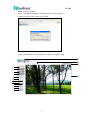
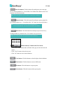
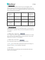
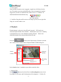
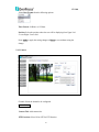
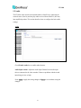
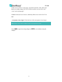
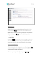
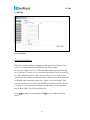
EVS410 4CH H.264 Video Encoder User’s Manual Copyright © EverFocus Electronics Corp, Release: May 2011 Rev. 0 EVS410 Product Name: EVS410 EverFocus 4CH H.264 Video Encoder Model Number(s): EVS410 FCC Notice "Declaration of Conformity Information" This equipment has been tested and found to comply with the limits for a Class A digital device, pursuant to part 15 of the FCC Rules. These limits are designed to provide reasonable protection against harmful interference in a residential Installation. This equipment generates, uses and can radiate radio frequency energy and, if not installed and used in accordance with the instructions, may cause harmful interference to radio communications. However, there is no guarantee that interference will not occur in a particular installation. If this equipment does cause harmful interference to radio or television reception, which can be determined by turning the equipment off and on, the user is encouraged to try to correct the interference by one or more of the following measures: - Reorient or relocate the receiving antenna. - Increase the separation between the equipment and receiver. - Connect the equipment into an outlet on a circuit different from that to which the receiver is connected. - Consult the dealer or an experienced radio/TV technician for help. Warning: Changes or modifications made to this equipment, not expressly approved by EverFocus or parties authorized by EverFocus could void the user's authority to operate the equipment. This device complies with part 15 of the FCC Rules. Operation is subject to the following two conditions: (1) This device may not cause harmful interference, and (2) This device must accept any interference received, including interference that may cause undesired operation. EverFocus Electronics Corp. 12F, No. 79, Sec. 1, Shin-Tai Wu Rd., His-Chi, Taipei Hsien, Taiwan, R.O.C. EVS410 complies with CE and FCC rules. 2 EVS410 About this document All the safety and operating instructions should be read and followed before the unit is operated. This manual should be retained for future reference. The information in this manual was current when published. The manufacturer reserves the right to revise and improve its products. All specifications are therefore subject to change without notice. Safety Notices -These limits are designed to provide reasonable protection against interference. This equipment may generates, uses and can radiate radio frequency energy and, if not installed and used in accordance with the instructions, may cause harmful interference to radio communications. However, there is no guarantee that interference will not occur in a particular installation. If this equipment does cause harmful interference to radio or television reception, which can be determined by turning the equipment off and on, the user is encouraged to try to correct the interference by one or more of the following measures: -Reorient or relocate the receiving antenna. -Increase these separations between the equipment and receiver. -Connect the equipment into an outlet on a circuit different from that to which the receiver is connected. -Consult the dealer or an experienced radio/TV technician for help. Any changes or modifications not expressly approved by the party responsible for compliance could void the user's authority to operate the equipment. To reduce risk of fire or electric shock, do not expose this device to rain or moisture. Do not attempt to disassemble the device. not remove screws or covers. To prevent electric shock, do There are no user-serviceable parts inside. Contact qualified service personnel for maintenance. Handle the device with care. Do not strike or shake, as this may damage the device. Do not use strong or abrasive detergents when cleaning the device body. Use a dry cloth to clean the device when it is dirty. 3 When the dirt is hard to EVS410 remove, use a mild detergent and wipe gently. Do not operate the device beyond its specified temperature, humidity or power source ratings. Do not use the device in an extreme environment where high temperature or high humidity exists. Use the device at temperature within 0°C ~50°C / 32°F~122°F and humidity below 90%. The input power source for this device is 12 VDC & 802.3af PoE. Use only the recommended power supplies. Power supplies must comply with the requirement of the latest version of IEC60950-1. Substitutions may damage the unit or cause a fire or shock hazard. Electrostatic-sensitive device. Use proper CMOS/MOSFET handing precautions to avoid electrostatic discharge. Installation should be performed by qualified service personnel only in accordance with the National Electrical Code or applicable local codes. Terms and Trademark Ethernet, Internet Explorer, Linux, Microsoft, Windows, WWW are registered trademarks of the respective holders. Other product names appearing in this User's Guide may be trademarks or registered trademarks of their respective holders. Java™ and all Java-related logos and trademarks are trademarks or registered trademarks of Sun Microsystems, Inc. in the United States and other countries. Support If the unit ever needs repair service, the customer should contact the nearest EverFocus Electronics Corp. Service Center for return authorization and shipping instruction. About this AC Adaptor Specifications for AC adaptor Power Supply: 12VDC, 5 A Power Output: 12VDC, 5 A Operating Temperature: 0℃ ~ 40℃ / 32۫F ~ 104۫F External Dimensions: 35 mm x 54.22 mm x 123.12 mm / 1.38” x 2.13” x 4.85” 4 EVS410 TABLE OF CONTENTS 1. INTRODUCTION..............................................................................................7 2. FEATURES ........................................................................................................7 3. ACCESSING THE MENU ................................................................................8 4. PLAYBACK .....................................................................................................15 5. SETTINGS .......................................................................................................17 5.1 SYSTEM INFO ................................................................................................17 5.1.1 Information Tab.....................................................................................17 5.1.2 Log Tab .................................................................................................18 5.2 USER CONFIG ................................................................................................19 5.3 NETWORK .....................................................................................................22 5.3.1 Network.................................................................................................22 5.3.2 DDNS....................................................................................................25 5.3.3 SMTP/FTP ............................................................................................26 5.3.4 HTTPS ..................................................................................................28 5.3.5 SNMP....................................................................................................31 5.3.6 Network Alarm (reserved for PowerCon).............................................33 5.4 VIDEO ...........................................................................................................33 5.4.1 Multi Streaming ....................................................................................34 5.4.2 Camera ..................................................................................................36 5.4.3 Privacy Mask ........................................................................................38 5.5 AUDIO ...........................................................................................................39 5.6 USER ...........................................................................................................40 5.7 EVENT.........................................................................................................42 5.7.1 Event Settings .......................................................................................43 5.7.2 Motion Detection ..................................................................................45 5.7.3 Tamper Detection..................................................................................46 5.7.4 Alarm I/O ..............................................................................................47 5.7.5 Schedule................................................................................................48 5.8 SYSTEM ......................................................................................................49 5.8.1 Date/Time..............................................................................................49 5.8.2 Daylight Saving ....................................................................................51 5.8.3 SD Card.................................................................................................52 5.8.4 Serial Communication ..........................................................................54 5.8.5 Maintenance..........................................................................................55 5 EVS410 4.9 EKB200........................................................................................................57 4.9.1 Action List.............................................................................................57 6. SPECIFICATIONS..........................................................................................60 6 EVS410 1. INTRODUCTION EverFocus EVS410 Video Encoder can enable transmission of H.264/MJPEG video streams of four analog cameras. The highly efficient H.264 video compression reduces bandwidth and storage requirements with superb video quality. Moreover, EVS410 offers built-in four high performance 3D de-noise and de-interlacer engines to reduce noise artifacts, increase S/N ratio, and covert videos from interlace to progressive. EVS410 can deliver independent video streams from each channel at full frame rate in all resolution up to 4CIF. Furthermore, users can individually configure with different compression formats, resolutions and frame rate to monitor and control analog cameras remotely over network. Featured with intelligent video capabilities such as video motion detection and camera tampering detection makes the EVS410 stand out from competition as the best choice for IP video surveillance system. 2. FEATURES Dual Codec for H.264 and MJPEG in 30 FPS frame rate in all resolutions H.264/MJPEG dual stream output and independent video stream configuration from each channel for simultaneous live monitoring and high resolution recording Built-in high performance 3D de-noise and de-interlacer engines to reduce noise artifacts, increase S/N ratio, and covert videos from interlace to progressive Smart Wizard settings for varied Event and schedule recording Support PTZ camera control via RS485 Built-in slot for an SDHC card enables local event or backup recording in the event of network interruptions Two-way Audio 7 EVS410 3. ACCESSING THE MENU Step 1. Start an Internet Explorer browser session. Before accessing to the EVS410 over IE browser, user should adjust the security level. Open the IE browser and set the security level to “Low” in “Tools->InternetOptions->Security->CustomLevel…”, and enable ActiveX Control and Plug-in directly as well. Step 2. Enter the IP address or host name of the device in the Location/Address field of your Internet Explorer browser in the form http://nn.nn.nn.nn:port, or http://ddnsname.everfocusddns.com. (Please refer to EVS410 Installation Guide for how to find the IP address by using the IP Finder) Step 3. At the login popup window enter “User Name” and “Password”. Default User name is “user1” and default password is “11111111”. 8 EVS410 Step 4. Click “OK” button. Step 5. You might be required to download Active X files, which are required to process video. Please click "Install". Step 6. Congratulations!! You should now be able to see the live image. 14 ○ 15 ○ 16 ○ 1 ○ 2 ○ 3 ○ 4 ○ 17 ○ 5 ○ 6 ○ 7 ○ 8 ○ 9 ○ 10 ○ 11 ○ 12 ○ 13 ○ 9 EVS410 1 Press ○ button to display the "Live" page. Double click on the image to show a full screen display, double click again or press ESC to return to the normal live display. 2 Press ○ button to go SD card playback page. Please refer to “Section 4. Playback" for further information. 3 Press ○ button to enter the Setting page. In the Setting page, there are 9 sections: [System Info], [User Config], [Network], [Video], [Audio], [User], [Event], [System] and [EKB]. Please refer to “Section 5. Setting” for further information. 4 Press ○ button to close the EVS410 network page. 5 Video Stream ○ Select Video Stream from CH1 Stream 1, CH1 Stream 2, CH2 Stream 1, CH2 Stream 2, CH3 Stream 1, CH3 Stream 2, CH4 Stream 1, CH4 Stream 2 and Quad view to view all 4 channels. (stream must be enabled in camera Setting menu). Please refer to "Section 5.4.1 Multi Streaming” for further information. Notes about Quad view: 1. Live view in Quad view mode: it only displays stream 1 for each channel. 2. View Size in Quad view mode: dual channel view in 704x480 view size only. 3. Manual Recording & Snapshot in Quad view mode will be done for all 4 CHs simultaneously. 4. Quad view does not support Digital Zoom function nor PTZ control function. 6 View Size ○ You can select View size to either reduce or enlarge the image to the appropriate size. Select the view size for live images from: 704*480(576)/640x480/352*240(288)/320x240/176*120(144) 10 EVS410 7 Record ○ The record button is used to record the current video stream. The location where the image file is saved can be specified in Setting -> User Config. Please refer to “Section 5.2 User Config” for further information. Note: Record segment is unlimited. However, if you switch to any other page, record will stop. 8 Snapshot ○ The Snapshot button saves a .jpg image of the video image currently being displayed. The location where the snapshot data is saved can be specified in Setting -> User Config. Please refer to “Section 5.2 User Config” for further information. 9 ~ ○ 10 Play Audio/Transmit Audio ○ Click the “Play Audio” and “Transmit Audio” buttons to switch the sound off and on for the audio input and output, respectively. 11 PTZ Control ○ Press button to open PTZ control window. Note: When PTZ function is ON, digital zoom function will be disabled. Press button to close PTZ control window. EVS410 provides 3 methods to control PTZ: A Control panel ○ B On Screen Control ○ C PTZ Control Shortcuts ○ 11 EVS410 A ○ B ○ C ○ A Control Panel ○ : Zoom in Focus near : Zoom out : Focus far : Iris + : Iris – Arrow buttons: Click on an arrow button to navigate in that direction. : stop current action. : User can select PTZ speed from High, Standard, Low and Minimum. Preset button: Click this button first, and input a preset position number by clicking number key and then click “Go” button to move the camera to a preset location. Note: To use this function, user need to set preset location in advance. 12 EVS410 Auto Pan button: Click this button first and input a preset auto pan No. by clicking number key (1 for AB Pan, 2 for Endless Pan) and then click “Go” button to run a preset auto pan. Note: To use this function, user need to set Auto Pan in advance. Pattern button: Click this button first and input a preset pattern No. by clicking number key (1 ~4) and then click “Go” button to run a preset Pattern. Note: 1. Click on live screen once to stop running pattern. 2. To use this function, user need to set Pattern in advance. Tour button: Click this button first and input a preset Tour No. by clicking number key and then click “Go” button to run a preset tour. Note: To use this function, user need to set tour in advance. Number button, Go button and Clear button: - Click desire number button and it will show in the gray text area at lower-left corner. - Click “Clear” button to clear the text area. - Click “Go” button to run a selected function. Clear button: Click this button to clear the digit selection indicator. Menu button: Click this button to enter to OSD menu. Set button: Click this button to set preset point. Delete button: Click this button to delete preset point. 13 EVS410 B On Screen Control ○ The whole screen is divided into 16 areas. Every area corresponds to a PTZ function, click on an area to execute the specific function of PTZ. Please see the table of the PTZ function with its mapping area number below. (Please refer to the above screenshot for the area number). 1. PTZ pan and tilt 2. PTZ tilt up to left and up directions 3. PTZ tilt up 4. PTZ pan and tilt to right and up directions 5. PTZ pan left 6. Focus Closer 7. Zoom In 8. PTZ pan right 9. PTZ pan left 10. Focus Further 11. Zoom Out 12. PTZ pan right 13. PTZ pan and tilt to left and down directions 14. PTZ tilt down 15. PTZ tilt down 16. PTZ pan and tilt to right and down directions C PTZ Control Shortcuts ○ Right click the mouse to get a PTZ Control Shortcuts panel. User can control the PTZ through a PC’s keyboard. The keys in red color correspond to the same keys of keyboard. 12 Manual Control – Trigger Event ○ Press “Trigger Event” button to trigger an event directly from the live view page, and event actions will be initiated if they have been set up in the “Event” menu. (Please refer to “Section 5.7.1 Event Settings”) 13 Manual Control – Reset Alarm ○ Press “Reset Alarm” button to reset an alarm condition remotely. 14 The ○ icon is used to fold the control panel at left and view the image in a full screen. Click on icon to unfold the control panel. 15 Status Display ○ The name of the device currently being viewed, current date/time and current frame rate will be displayed. 14 EVS410 16 Event signals ○ When an alarm or motion event is triggered, a signal icon will flash to alert the user. The motion event icons which differed by colors correspond to the motion trigger areas you have set in Motion menu. Please refer to “5.7.2 Motion” for detailed information about Motion setup. Rec Alarm Motion 17 Scroll bar: Drag the scroll bar to move the image up, down, left or right if the ○ image size exceeds window’s size. 4. Playback Playback button is only active when SD card is inserted. If SD card is not inserted, Playback button will be disabled. Administrator can set user’s authority, to allow/disallow user to view information from the SD card. Below is the detailed description about remote playback from SD card. Press the button to enter Playback page. Playback is divided into 3 main sections: Search Controls, Playback Window and Recording List. Playback Window Search controls Recording List In the Search section, 3 methods are provided to search the video: 1. Search by File: Press button to list all the files in the Recording List section. In the Recording List, file name and file information will be displayed. Click the file 15 EVS410 name that you wish to playback and press button. 2. Search by Time: Press the calendar icon to select the date and time to be searched. Press button to start time search. In “Recording List” section, the file name and file information that is the most close to the specified time will be displayed. Click the file name that you wish to playback and press button. 3. Search by Event: Select which event type(s) to search for. Choose from Alarm, Motion or Video Loss. Select “Start Time” and “End Time”. Press “Search” button to start time search. In “Recording List” section, file name and file information will be displayed. Click the file name that you wish to playback and press button. Check “Multiple Files” and the playback function will keep playing to next file until the end of file list in the same folder. Check “Loop Again” and playback function will loop playback the selected file. Playback the selected video Pause the playback video Stop the playback video Snapshot the current image. The video image currently being displayed will be saved as a .jpg file. The location where the snapshot data is saved can be specified in “Setting -> User Config. “. Please refer to “Section 5.2 User Config” for further information. Zoom In the image Zoom Out the image Archive the video file. Specify the recording path if you wish to save the file to your local PC. Lock the selected file. The file saved in the SD card will be 16 EVS410 overwritten if the setting in “System->SD Card->Overwrite” is ON, however the data being locked will be protected from overwriting. Remotely remove the selected file from SD card. Press button to return to live view. 5. SETTINGS Click this button to display the setup menu. Note: Press button anytime to return to live view. 5.1 System Info System information and system log events can be accessed on this page via 2 tabs: [Information] tab and [Log] tab. 5.1.1 Information Tab System Information: Firmware version, MAC address, Model Name and TV Out format. (this data may not be changed in this page and is for reference only) 17 EVS410 5.1.2 Log Tab System Log: Date/Time: displays date and time of the log event. Log message: all information and event message, including login, user’s IP, reboot, firmware upgrade, load factory default, configuration reset and event detected. System will keep the newest 256 records. 18 EVS410 Press button to export the system log into a “.txt” file and select the location where the exported log file will be saved. 5.2 User Config The configuration and operation of the Live View screen can be changed based on the login user ID. The settings which can be customized for each of the 10 possible login IDs are: Video/Audio Connection Protocol Setting Protocol Options: Select Video/Audio connection protocol from RTP over UDP/RTP over TCP/RTP over HTTP. Depending on user’s network environment, there are three connection protocols: RTP over UDP: This protocol allows for more real-time audio and video streams. However, network packets may be lost due to network burst traffic and images may be broken. Activate UDP connection when occasions require time-sensitive responses and the video quality is less important. Note that each 19 EVS410 client connecting to the server takes up additional bandwidth and the video encoder allows up to ten simultaneous accesses. RTP over TCP: This protocol guarantees the complete delivery of streaming data and thus provides better video quality. The downside of this protocol is that its real-time effect is not as good as that of the UDP protocol. RTP over HTTP: This protocol allows the same quality as TCP protocol without needing to open specific ports for streaming under some network environments. Users inside a firewall can utilize this protocol to allow streaming data through. Press Apply to apply the setting changes or Reset to reset without saving the changes. Text Settings Check the box to enable display of the Machine name, Channel Title, Date/Time or Frame Rate on the screen. Foreground Color: Select the foreground color of text to be displayed by moving the slide bar between Red, Green and Blue until the desired color is obtained. Position: Select the position where the text will be displayed: Upper Left / Lower Right / Lower Left. Note: For Quad view, position of text will be fixed at Upper Left. Press Apply to apply the setting changes or Reset to reset without saving the changes. Date/Time Format Used in Text Select Date/Time Format from the following options: * day of week, Month, date, year Time Format: choose between 24 Hours or 12 Hours. 20 EVS410 Press Apply to apply the setting changes or Reset to reset without saving the change. Recording/Snapshot Export Setting Enable Event Recording to PC: Allow event video recorded to users' PC if any events have been set to record to PC. Export folder: Select Export folder by clicking on the folder to be exported. button, then direct to File size: Set the limit for the size of the single recording file in minutes. When the single recording file size exceeds the time you set, the system will create a new file to continue recording. Overwrite: Select “ON” for overwriting recording/snapshot file when the disk storage capacity is full. If the remaining hard disk capacity is less than ____ MB (enter the value you wish to set between 50~2000), the system will stop recording or start overwriting. Press Apply to apply the setting changes or Reset to reset without saving the changes. Language Settings Language: Select the language to be displayed in web page. Default language is English. To add a new language which is not listed in the original configuration, press the Browse button to locate the new language file (.evb) and then click the Load button. Note: Uploading a new language file will reboot the system automatically. Please reconnect to the Video encoder after reboot. Press Apply to apply the setting changes or Reset to reset without saving the change. 21 EVS410 5.3 Network The network settings and the settings relating to Network, DDNS, SMTP/FTP, SNMP and Network Alarm can be configured on this page. The "Network setup" page has 6 tabs: [Network] tab, the [DDNS] tab, the [SMTP/FTP] tab, the [HTTPS] tab, the [SNMP] tab and the [Network Alarm] tab. 5.3.1 Network The following information is required to configure the network settings. Contact the network administrator or your Internet service provider. IP Settings • IP Type • IP address • Subnet mask • Gateway (when using the gateway server/router) • Primary DNS, Secondary DNS (when using DNS) IP Type DHCP: Configure the DHCP server not to assign the same IP addresses used 22 EVS410 for the other video encoder and PCs whose IP address is unique. Refer to the network administrator for the settings of the server. Default: DHCP. Note: If a DHCP server is not available, the system will use xxx.xxx.xxx.xxx as the default IP address. Static IP: User can manually set the static IP for network connection. PPPoE: This is for a DSL DIRECT connection application; the ISP will require a user name and password. (That is, if a single video encoder is connected directly to the DSL modem.) Note: If PPPoE is used as IP type, IP Utility software will not be able to detect the device. IP address When not using DHCP, enter the IP address of the video encoder. Avoid address conflicts; do not enter an IP address already used for a PC or other video encoders. Every device on an IP network must have a unique IP address. Subnet Mask This field is to set the netmask for your network so as the video encoder will be recognized within the network. Example: 255.255.255.000 typical for a Class “C” network. When DHCP is selected, the DHCP server will assign this value automatically. Gateway This field is to set the gateway for your network so the video encoder will be recognized within the network. When DHCP is selected, the DHCP server will assign this value automatically. Primary DNS An IP address of DNS server that is provided by ISP. This address may be assigned automatically if DHCP is used. A correct DNS IP is essential if DDNS will be used. Secondary DNS If your ISP provides you an IP address secondary DNS, please set it here. 23 EVS410 Username Enter User name of the account (used only for PPPoE). Password Enter Password of the account (used only for PPPoE). Port Settings HTTP Port Enter HTTP port number. HTTPS Port Enter HTTPS port number. RTSP Port Enter RTSP port number. Multicast Setting Multicast provides the most efficient usage of bandwidth when there are large numbers of clients viewing simultaneously. A multicast broadcast cannot however, pass a network router unless the router is configured to allow this. It is not possible to multicast over the Internet, for example. Note also that all multicast viewers count as one unicast viewer. Enable Multicast: Check the box to enable multicast. Multicast provides the most efficient usage of bandwidth when there are large numbers of clients viewing simultaneously. A multicast broadcast cannot however, pass a network router unless the router is configured to allow this. It is not possible to multicast over the Internet, for example. Note also that all multicast viewers count as one unicast viewer Multicast IP: Enter the multicast IP address. Port: Enter the multicast port. Time to live: Enter the multicast TTL value. It is a limit on the period of time or number of iterations or transmissions in computer and computer network 24 EVS410 technology that a unit of data (e.g. a packet) can experience before it should be discarded. Press Apply to apply the setting changes or Reset to reset without saving the change. 5.3.2 DDNS DDNS settings When accessing the video encoder via the Internet in a network environment where the site IP address is obtained using DHCP, the DDNS function is necessary. To use the DDNS function, it is necessary to connect to the dedicated DDNS server. We support 4 DDNS server providers as follows: ○ ○ ○ ○ www.everfocusddns.com www.sitelutions.com www.dyndns.com www.no-ip.com 4 4 4 Enable: Check the box to enable DDNS setting. 25 EVS410 Service ISP: If you choose EverFocus DDNS server, you can easily register a DDNS name and obtain free DDNS services from EverFocus at ”www.everfocusddns.com”. 5 Enter an IP Cam Account Name: Press .everfocusddns.com button to register or update DDNS account. If you wish to get a domain name from another DDNS provider, it may be necessary to configure Record ID, FQDN, Username and password and register in advance for DDNS services. Refer to the web site for further information about the DDNS provider. Press Apply to apply the setting changes or Reset to reset without saving the change. 5.3.3 SMTP/FTP Set SMTP Server (email) The settings relating to the mail server used to send the e-mail notification from the video encoder to predefined addresses via SMTP can be configured. 26 EVS410 SMTP Server: Enter the IP address or the host name of the SMTP server used to send e-mails. SMTP Port: Enter the port number for SMTP. Default is 25. Authentication: Check the box if the SMTP server requires Authentication (user/ password). User Name: Input the login user ID if the SMTP server requires Authentication. (max. 31 bytes; a-z;A-Z;0-9;@) Password: Input the password if the SMTP server requires authentication. (max. 15 bytes; a-z;A-Z;0-9;@) Receiver Address: Input the e-mail address to receive an e-mail message when the EVENT is enabled and triggered. Please use “;” to separate address. Sender Address: Input sender’s e-mail address, so that receiver can recognize the sender when an event message is sent out. Attach image: Check the box to send an e-mail notification with a FPS video file attached. This server requires a secure connection (SSL): Check the box to allow a secure connection for the server. SSL encrypts the segments of network connections above the Transport Layer, using symmetric cryptography for privacy and a keyed message authentication code for message reliability. Send Test Mail: Press designated address. button to send a test e-mail to the Set FTP Server The settings relating to an FTP server to be used to receive alarm images can be configured. FTP Server: Enter the IP address or the host name of the FTP server. 27 EVS410 FTP Port: Enter the port number for FTP server. Default is 21. Recording Path: Assign the recording path. User Name: Set FTP User name. Password: Set FTP password. PASV mode: Check to enable Passive mode (most sites normally require Passive mode). If unable to establish a connection, uncheck "PASV" mode. Test FTP Server: Press FTP server. button to send a test file to the designated Press Apply to apply the setting changes or Reset to reset without saving the change. 5.3.4 HTTPS Hypertext Transfer Protocol Secure (HTTPS) is a combination of the Hypertext Transfer Protocol with the SSL/TLS protocol to provide encrypted communication and secure identification of a network web server. 28 EVS410 Before using HTTPS for communication with the Video Encoder, a Certificate must be created first. There are two ways to create and install a certificate: Create self-signed certificate: A self-signed certificate can be used until a Certificate Authority-issued certificate has been obtained. Click button to install a self-signed certificate. Although self-signed certificates are free and offer some protection, true security is only implemented after the installation of a signed certificate issued by a certificate authority. The Certificate Information will automatically be displayed as shown below. Create Certificate Request - A signed certificate can be obtained from an issuing Certificate Authority by clicking button. The Certificate Information will automatically be displayed as shown below. Press Apply to apply the setting changes or Reset to reset without saving the change. Created Request The properties of any certificate request currently resident in the video encorder or installed can be viewed by clicking the Properties button. The pop-up window shows an example of a certificate request. 29 EVS410 To create and install other certificates, please remove the existing one. Press Remove button to erase the certificate. Install Signed Certificate When the signed certificate is returned, press Browse button to search for the issued certificate and press Upload button to import the certificate. Installed Certificate Information Press Property button to view the property of self-signed certificate. To create and install other certificates, please remove the existing one. Press Remove button to erase the certificate. The pop-up window shows an example of a self-signed certificate. 30 EVS410 5.3.5 SNMP This page allows the user to set SNMP settings so it can be used by a NMS (Network Management System). Set SNMP Server SNMP is the Simple Network Management Protocol. The SNMP protocol is used by network management systems to communicate with network elements. Many network elements support only SNMPv1, SNMPv2 and SNMPv2c. Support for SNMPv3 is minimal. Version Description SNMPv1 SNMPv1, which implements community-based security SNMPv2c SNMPv2 with community-based security SNMPv2 SNMPv2 with party-based security SNMPv3 SNMPv3, which implements user-based security Enable SNMP v1/v2/v2c: Check the box to enable SNMP v1/v2/v2c. 31 EVS410 Read-Only Community: Identifies the community string for read-only access. The community string has to be the same as that set in NMS. Read-Write Community: Identifies the community string for read and write access. The community string has to be the same as that set in NMS. Trap Community: The community string used for the traps. Trap Address: Identifies the IP address of the trap destination Enable SNMP v3: check the box to enable SNMP v3. Read-only Username: Set the user name to be used for authentication and privacy. (Read-only) Read-only Auth. Method: Select authentication method which will be used with the password to authenticate with the device. (Read-only) Read-only Auth. Key: Set authentication password. (Read-only) Read-only Privacy method: Select the privacy method which will be used with the encryption password. (Read-only) Read-only Privacy key: Set privacy password. (Read-only) Read-Write Username: Set the user name to be used for authentication and privacy. (Read-write) Read-Write Auth. Method: Select authentication method which will be used with the password to authenticate with the device. (Read-write) Read-Write Auth. Key: Set authentication password. (Read-write) Read-Write Privacy Method: Select the privacy method which will be used with the encryption password. (Read-write) Read-Write Privacy Key: Set privacy password. (Read-write) 32 EVS410 5.3.6 Network Alarm (reserved for PowerCon) Set Network Alarm This function is reserved for PowerCon software, for the details regarding these settings please refer to the documentation for the PowerCon network alarm protocol. 5.4 Video The settings relating video such as streaming, video encoder can be configured on this page. The "Video" page has 3 tabs: the [Multi-streaming] tab, the [Camera] tab and the [Privacy Mask] tab. 33 EVS410 5.4.1 Multi Streaming Stream Settings The system can output 2 video streams simultaneously for each channel. For each of them, the user can set compression format, resolution and frame rate individually. Stream 1 is always enabled for live view. Check “Enable” box to enable stream2. Channel: Select channel number for the stream settings. Format: Select compression format from H.264 and MJPEG. Bit Rate: The bit rate can be set as Variable Bit Rate (VBR) or Constant Bit Rate (CBR). Constant Bit Rates: 3M/2M/1.5M/1M/750K/500K/384K/256K /128K/64K/32Kbit/s CBR allows you to set a fixed Target bit rate that consumes a predictable amount of bandwidth. As the bit rate would usually need to increase for increased image activity, but in this case cannot, the frame rate and image quality are affected negatively. 34 EVS410 Variable Bit Rates: Highest/High/Normal/Low/Lowest VBR adjusts the bit rate according to the image complexity, using more bandwidth for increased activity in the image, and less for lower activity. Resolution: Stream 1 704 x 480 (576) 4CIF / 640 x 480 VGA / 352 x 240 (288) CIF Stream 2 352 x 240 (288) CIF / 320 x 240 QVGA / 176 x 112 (144) QCIF Frame Rate: select from NTSC: 30 / 15 / 10 / 7.5 / 6 / 3 / 1 fps ; PAL: 25 / 12.5 / 8 / 6 / 5 / 2.5 / 1 fps Note: 1. Bandwidth utilization will be in proportion to the quality setting, with highest quality requiring highest bandwidth. 2. System performance may be influenced if user enables 2 video streams simultaneously. Press Apply to apply the setting changes or Reset to reset without saving the change. Video Recording Settings User can set video recording by selecting one of the enabled video stream. This will allow users to view live images while also recording video from another video stream. Channel 1~4: Select video recording stream from any enabled stream. Selections are Stream 1 / Stream 2. Video Stream: Recording file will be saved as AVI or ARV, select which file format is to be used. Time Stamp Settings User can setup the Date/Time to be stamped on the video steam. Date/Time: Check the box to enable time stamp function. 35 EVS410 Select Date Format from the following options: Time Format: 24 Hours or 12 Hours. Position: Select the position where the text will be displaying from Upper Left / Lower Right / Lower Left. Press Apply to apply the setting changes or Reset to reset without saving the change. 5.4.2 Camera Channel: Select the channel to be configured. Camera Settings Camera Title: Add camera title. PTZ Function: Select ON or OFF for PTZ function. 36 EVS410 ID: This entry is used to assign the own ID code of the camera. Protocol: Select protocol from Everfocus, Pelco-D, Pelco-P, Samsung and Panasonic. Press Apply to apply the setting changes or Reset to reset without saving the change. Image Settings Brightness: to increase or decrease object contrast of images. It is adjustable from 0~255. Contrast: to increase or decrease object contrast of images. It is adjustable from 0~255. Hue: to increase or decrease hue of video images. It is adjustable from 0~255. Saturation: to increase or decrease color saturation of video images. It is adjustable from 0~255. Press Apply to apply the setting changes or Reset to reset without saving the change. 37 EVS410 5.4.3 Privacy Mask This mode masks areas you do not want to display on the screen or record. User can define the area to be hid by clicking on 2 points sequentially to form a rectangular on the preview window with the mouse. The rectangular area between these 2 points is filled with color and this is the privacy mask area. Press to update the current image. Press to have the entire screen selected for privacy mask. Press to clear all selections. Press and click on the rectangular, to erase that area/ There are 4 privacy mask trigger areas, which can be distinguished by 4 different colors. Area: Enter Privacy Mask Area name. Check Enable checkbox to enable event actions related to that area. Press Apply to apply the setting changes or Reset to reset without saving the change. 38 EVS410 5.5 Audio The EVS410 video encoder can transmit audio to client PCs by connecting an external source (line-in), and can play audio received from client PCs (line-out) into amplified speakers. This section describes how to configure the basic audio settings. Audio Check Enable Audio box to enable audio function. Audio Input volume: Adjust the Audio Input Volume for the audio input devices connected to the video encoder if there are problems with the sound input being too low or high. Press Apply to apply the setting changes or Reset to reset without saving the changes. 39 EVS410 5.6 USER Press Add to add a user, press Modify to modify a user, press Remove to remove a user. User Information Account: Enter account name. Description: Enter description. Password: Enter a password. Authority: Select authority type from Supervisor, Administrator, User and Guest. Status: Status of the account, select from Active and disable. SD Card Playback: Select ON to allow the user to playback SD card data. Select Off to resist the user to playback SD card data. Maximum 10 user IDs can be created to access the video encoder. The user information screen displays the authorized IDs. Access levels are: • Supervisor/Administrator –a supervisor/administrator has unrestricted access to the Setting menus and can determine the registration of all other users. However, an administrator is not allowed to change a supervisor’s account and password. 40 EVS410 • User- can view the Live View page, system info, network, video, audio, and adjust user config settings. The User level does not have access to the “user”, “event” and “system pages”. • Guest- the lowest level of access, which only allows access to the Live View page. Anonymous viewer login: Check the box to allow anonymous viewer login. Note: Please select Active in Status section to activate an account. Press Apply to apply the setting changes or Reset to reset without saving the changes. 41 EVS410 5.7 EVENT An event in the video encoder is when an Event Type is activated and causes certain actions to be performed. The event type is the set of conditions that specifies how and when which actions will be performed. This table describes how to setup action types and event type. Event Type Notification Type Motion Alarm Manual Detection Video Tampering Schedule Pre/Post- Action Input1~4 Trigger (CH1~4) Loss x x Detection Recording Alarm Settings Trigger Alarm output x x x Send Mail Attached notification x x x x x Upload to FTP x x x x x x x Card x x x x x x x Record to PC x x x x x x x Alarm x x x x x Log x x x x x I-frame Record to SD Network Re-trigger Alarm -- x Note: 1. * Record to PC only works when PC and IP camera are connected. 2. **Only Upload to FTP can be selected to record event video to remote site. 3. Up to 10 event types can be configured in the camera, and up to 3 of these can be configured to upload images. 42 EVS410 5.7.1 Event Settings The settings relating to event occurrences such as settings for motion, alarms and schedule can be configured on this page. The "Event " page has 5 tabs: [Event Settings] tab, [Motion Detection] tab, [Tamper Detection] tab, [Alarm I/O] tab and [Schedule] tab. Event List button to add an event condition. Press To modify the event list, click on the event and it will be highlighted. Press button to modify the setting. To remove an event from event list, click on the event and it will be highlighted. Press button to remove the event. Check Enable checkbox to activate event actions when the event occurs in the specified time zone. To change the priority of events, click on the event and it will be highlighted. Press or button to change the priority of events. The 43 EVS410 event that has highest priority will be activated first. Press Apply to apply the setting changes or Reset to reset without saving the change. This example describes how to set the video encoder to upload images to an FTP site when someone press Manual trigger button: button in Event page. 1. Click 2. Enter an event name for the event, e.g. Event 1. 3. Select “Manual Trigger” as event type. 4. Select “Upload to FTP” as action type. 5. Check “Enable This Event”. 6. Check “Enable Pre-Trigger Buffer” and “Enable Post-Trigger Buffer”. 7. Click to save this event in event list. Pre/Post Trigger Settings This function is used to be able to review what happened immediately before and after a trigger, e.g. 5 seconds before or after a motion has been detected, or after motion detection ceases. 44 EVS410 Pre-Trigger Buffer: Image saved internally in the video encoder from the time immediately preceding the trigger. Input the desired length of pre-trigger buffer time. It can be set up to 120 seconds. Post-Trigger Buffer: Image saved internally in the video encoder from the time immediately after the trigger condition has ceased/been reset. Input the desired length of post-trigger buffer time. It can be set up to 120 seconds. Press Apply to apply the setting changes or Reset to reset without saving the change. 5.7.2 Motion Detection Motion Detection Channel: Select the channel to be configured. User can define the motion areas to be detected by clicking on 2 points sequentially to form a rectangular on the preview window with the mouse. The rectangular area between these 2 points is filled with color and this is the motion areas. Press Press to update the current image. to have the entire screen selected for motion detection. 45 EVS410 Press to clear all selections. Press and click on the polygon, to erase that polygon. There are 4 possible motion trigger areas, which can be distinguished by 4 different colors. Check the Enable checkbox to enable event actions related to that area. For each area, you can set the event action in response to motion detection in that area. Event actions can be set in “Event” section. In addition, you can set the Sensitivity level for the motion trigger separately for each area by selecting from 1 (low), 2, 3, 4, 5, 6, 7, 8, 9 to 10 (high). Press Apply to apply the setting changes or Reset to reset without saving the change. 5.7.3 Tamper Detection Tamper Detection Settings The video encoder tampering application generates an alarm whenever the video encoder is repositioned, or when the lens is covered, sprayed, or severely defocused. You must first create an event for the video encoder to send an alarm. 46 EVS410 Trigger Duration Time: Set the trigger duration time from 10~120 secs. Press Apply to apply the setting changes or Reset to reset without saving the change. 5.7.4 Alarm I/O Alarm Settings Input (1~4) Triggering Type: Select from Normal Close and Normal Open. (Default: Normal Open) Output Contact Type: Select from Normal Close and Normal Open. (Default: Normal Open) Press Apply to apply the setting changes or Reset to reset without saving the change. 47 EVS410 5.7.5 Schedule The event will start at the specified schedule. After selecting a time zone, the block will show the time zone settings. How to set a schedule: Select the edit actions of “Event Recording”, “Schedule Recording”, “Event+Schedule” or “deselect”. The first 3 actions are distinguished by 3 different colors. There are 24 blocks (one block = 1hr) on the time bar representing 24 hours respectively. Set a schedule start time by clicking on a desired start time block on a time bar. The selected blocks will turn the representing color, which means this color timezone has been set to the event schedule. The deselected blocks will turn back the original background color, which means the timezone has not been set to the event schedule. Press Apply to apply the setting changes or Reset to reset without saving the change. 48 EVS410 5.8 SYSTEM Date/Time, Daylight Saving, SD card and Maintenance settings can be accessed on this page. The "System" page has 5 tabs: [Date/Time] tab, [Daylight Saving] tab, [SD card] tab, [Serial Communication] tab and [Maintenance] tab. 5.8.1 Date/Time Machine Name Setting Machine Name: Enter the name for the video encoder. The entered name will be displayed in the status display area, and used to label any recoding and/or snapshot folders created on a user’s PC. Press Apply to apply the setting changes or Reset to reset without saving the change. Set Time Zone Time Zone: Select a time zone according to where the video encoder is located. 49 EVS410 Set Date/Time Manually Date: Click the calendar and pick the date. Press << to go previous year, < to go previous month, > to go next month and >> to go next year. Time: Click on Hour, Minute, Seconds, am/pm; then use up arrow to increase value and down arrow to decrease value. Press Apply to apply the setting changes or Reset to reset without saving the change. Set Date/Time Sync. Check Enable NTP checkbox to enable NTP server. NTP server: Time automatically adjusted by synchronizing with NTP server will be used as the standard time for the video encoder. Sync. Internal: Select an interval (1 - 24 hours: in 1 hour intervals) to elapse between synchronizations with the NTP server. Press Apply to apply the setting changes or Reset to reset without saving the change. 50 EVS410 5.8.2 Daylight Saving Set Daylight Saving Check Enable Daylight Saving checkbox to enable daylight saving. Set the start time for daylight saving time. Set the start week for daylight saving time: 1st / 2nd / 3rd / 4th / Last Set the start day of the week for daylight saving time: Sunday / Monday / Tuesday / Wednesday / Thursday / Friday / Saturday Set the start month for daylight saving time: January / February / March / April / May / June / July / August / September / October / November / December. Set the starting time for the change to daylight saving time: Choose the “From” time and “End” time when daylight saving starts. Set the end time from daylight saving time. Set the end week from daylight saving time: 1st / 2nd / 3rd / 4th / Last Set the end day of the week from daylight saving time: Sunday / Monday / Tuesday / Wednesday / Thursday / Friday / Saturday Set the end month from daylight saving time: January / February / March / April / May / June / July / August / September / October / November / December. Set the ending time for the change from daylight saving time: Choose the “From” time and “End” time when daylight saving ends. Press Apply to apply the setting changes or Reset to reset without saving the change. 51 EVS410 5.8.3 SD Card Setup SD Card Notification: Notification will be made via e-mail when the remaining space of the SD memory card reached the value selected from the following. 50%, 20%, 10%, 5%, 2%, 0% Notes: 1. When "50%" is selected, e-mail notification will be made each time the remaining space reaches 50%, 20%, 10%, 5%, 2% and 0%. 2. E-mail notification may not always be made at a very moment when the remaining space of the SD memory card reaches the selected value. Event Recording: FTP backup only: Event video will record to the SD card when the network connection to the FTP server is unavailable. Event Recording: Follows the event action settings you have made in the “Event” menu to record event video to the SD card. Both: Event video will record to SD for both of the above situations. Overwrite: Select ON for overwriting older data when the SD card memory is full. Select OFF for no overwriting the SD card data. Note: no recording can take place if the SD card is full and Overwrite is “Off”. 52 EVS410 Press Apply to apply the setting changes or Reset to reset without saving the change. SD Card Utility The total size and available size of the SD memory card will be displayed. Depending on the state of the SD memory card, the information will be displayed as follows: Indication Description Capacity ___ MB, available ___MB, used ___ % Formatting the SD Card Before formatting the SD memory card, it is necessary to press the button. Once the button is pressed, the button will be shown for a user to re-insert the SD card. Press button to format SD card. To obtain images from the SD memory card 1. Directly attach the SD card to a PC after removing the SD card from the video encoder. Access the video encoder using the Windows command prompt or FTP client software. → The window with the user name and password entry fields will be displayed. 2. Enter the user name whose access level is "Administrator" and its password. → Log in the video encoder. 3. A directory of all saved data will be displayed. You are now ready to obtain images from SD card. Note: - It is impossible to access the SD memory card in the process of formatting. - All data saved on the SD memory card will be deleted when the SD memory card is formatted. - Do not turn the power of the video encoder off in the process of formatting. 53 EVS410 5.8.4 Serial Communication RS485 Settings Baud Rate: This field is to set the speed at which is used to transmit instruction or information through the RS485 port on the video encoder. There are six different speeds, 2400/4800/9600/19200/38400/57600. (Default: 9600) Data Bit: This field is the data bit at which you will be transferring. There are two settings for this option: 8 or 7. (Default: 8) Stop Bit: This field is to set the stop bit for the RS485 connection. There are two different stop bits, 1 or 2. (Default: 1) Parity: This field is to select the parity level at which you will be connected. You can choose between None, Odd, or Even parity levels. (Default: none) Press Apply to apply the setting changes or Reset to reset without saving the change. 54 EVS410 5.8.5 Maintenance Maintenance Server Reboot: The unit is rebooted without changing any of the settings. Use this method by pressing Reboot button if the unit is not behaving as expected. Restore: The unit is restarted and most current settings are reset to the factory default values by pressing Restore button. The only settings saved are: IP setting DDNS setting Default: The Default button should be used with caution. Pressing this button will return all of the video encoder's settings, including the IP address, to the factory default values. The video encoder will then have to be re-installed. Save/Load Configuration Server To take a backup of all of the settings in the current configurations, press Save to save the configurations to a config. file. Once saved, it is then possible to return to the previous settings if/when desired. To return to a previously saved configuration, press the Browse button to 55 EVS410 locate and select the saved config. file (see above) and then click the Load button. The settings will be restored to the previous configuration. Upgrade Firmware Upgrade the EVS410 with the latest firmware. Press the Browse button to locate the firmware file. Press the Upgrade button to upgrade the firmware. Note 1: Do not disconnect power to the unit during the upgrade. The unit reboots automatically after the upgrade has completed. (1-5 minutes.) 2. During upgrade process, all event recording actions will be stopped. They will resume after the camera is rebooted. 56 EVS410 4.9 EKB200 4.9.1 Action List EKB200 Button Mapping EKB-200 is an IP surveillance keyboard controller powered by USB port. User needs to set related control for each EKB-200 key in this window. In Action list window, there are 12 EKB-200 button mapping options (From Key No.1 to Key No.12) can be set. User can choose action and set value for each Key No. If the command requires a value, such as GoTo Preset [x] or Tour [x], user needs to enter the number [x] in the field "Value". Otherwise, the value option will be disabled. After completing setting, press “Apply” to save the changes. Then user can use these keys and joystick on EKB200 to control these actions. Key No. 13 to Key No. 16 are system preset buttons also allowing user to do operations, such as IRIS+, IRIS-, Focus Near and Focus Far. Press Apply to apply the setting changes or Reset to reset without saving the change. 57 EVS410 Joystick IRIS- FOCUS NEAR IRIS+ FOCUS FAR 1 ○ 3 ○ 2 ○ 5 ○ 7 ○ 8 ○ 9 ○ 10 ○ 11 ○ 6 ○ 4 ○ 12 ○ EKB200 Panel There are 20 available Action options, including: 1. Set Preset: When the action of a key is set “Set Preset”, use joystick to select a position and press this key on KEB200 to save the position as Preset Point. 2. Goto Preset: When the action of a key is set “Goto Preset”, press this key on KEB200 and the system will go the Preset Point. 3. Goto Home: When the action of a key is set “Goto Home”, press this key on KEB200 and the system will go the Preset position. 4. Clear Preset: When the action of a key is set “Clear Preset”, press this key on KEB200 to clear the Preset Point. 5. Focus Near: When the action of a key is set “Focus Near”, press this key on KEB200 to do focus near. 6. Focus Far: When the action of a key is set “Focus Far”, press this key on KEB200 to do focus far. 7. Iris Open: When the action of a key is set “Iris Open”, press this key on KEB200 to do Iris open. 8. Iris Close: When the action of a key is set “Iris Close”, press this key on KEB200 to do Iris close. 9. Run Autopan: When the action of a key is set “Autopan”, press this key on 58 EVS410 KEB200 to start autopan. 10. Stop Autopan: When the action of a key is set “Stop Autopan”, press this key on KEB200 to stop autopan. 11. OSD Menu On: When the action of a key is set “OSD Menu On”, press this key on KEB200 to display OSD Menu on the screen. 12. OSD Menu Cancel: When the action of a key is set “OSD Menu Cancel”, press this key on KEB200 to hide OSD Menu on the screen. 13. OSD Menu Enter: When the action of a key is set “OSD Menu Enter”, press this key to enter the submenu of an option of OSD menu, only if this option has a <┘ mark right next to it. 14. Tour Run: When the action of a key is set “Tour Run” and the value of the key is set to a preset tour number, press this key on KEB200 to run this preset tour. 15. Tour Stop: When the action of a key is set “Tour Stop”, press this key on KEB200 to stop running a tour. 16. Pattern Run: When the action of a key is set “Tour Run” and the value of the key is set to a preset pattern number, press this key on KEB200 to run this preset pattern. 17. Pattern Stop: When the action of a key is set “Pattern Stop”, press this key on KEB200 to stop running a pattern. 18. Set Auto Tracking: When the action of a key is set “Auto Tracking”, press this key on KEB200 to switch auto-tracking on/off. 19. Toggle Fullscreen: When the action of a key is set “Toggle Fullscreen”, press this key on KEB200 to switch screen to current size/fullscreen. 20. Select Tracking Object: When the action of a key is set “Select Tracking Object”, user can set select tracking object firstly press this key on KEB200. An icon will display on the screen. Use joystick to select desired object and press this key again save the selected object. 59 EVS410 6. SPECIFICATIONS VIDEO STREAMING Video Compression Video Resolution Video Quality Frame Rate Video Source H.264/M-JPEG 704*480(576)/640x480/352*240(288)/320x240/176*112(144) VBR: 5 level adjustable, CBR: 256Kbps~3Mbps Up to 30fps 4 BNC composite, 1 V p-p / 75Ω NTSC/PAL auto-sense AUDIO Compression Method G.711 PCM 8 kHz Audio Input 1 Vrms ; 3.5mm phone jack; Mono Audio Output 1 Vrms ; 3.5mm phone jack; Mono Operation Mode NETWORK Two-way audio Interface 10Base-T/100Base-TX auto-negotiation, RJ-45 socket Support MDI/MDI-X auto crossover function Supported Protocols TCP/IP,UDP,ICMP,DHCP,NTP,DNS,DDNS,SMTP,SNMP,FTP,HTTP,HTTPs,PPPoE, UPnP,Bonjour,RTP,RTSP,RTCP,UDP,IGMP,ICMP,ARP,ONVIF,PSIA TERMIANL I/O Alarm Input/Output RS485 EVENT MANAGEMENT Event Trigger Notifications LOCAL STORAGE Pre- and Post- alarm buffer SD Card POWER Power Supply Power Consumption PHYSICAL Weight Dimensions ENVIRONMENTAL 4/1 Yes Alarm input, Manual trigger, Motion detection, Video loss, Tampering detection and Schedule recording Trigger alarm output, Send mail notification, Upload video to FTP, Record video to SD card, Record video to PC and Network alarm 40MB Secure Disk physical layer specification version 2.0 Supports SDHC Host Specification 12 VDC 36W max. 665g / 1.47 lbs 131(W) x 38.4(H) x 164.4(D)mm / 5.2” (W) x 1.5” (H) x 6.5” (D) Operating Temp. 0°C ~50°C / 32°F~122°F Humidity Certifications (20%~80% Humidity) CE/FCC 60 EVS410 EverFocus Electronics Corp. EverFocus Taiwan: 12F, No.79, Sec. 1, Shin-Tai Wu Road, Hsi-Chih, Taipei, Taiwan TEL: +886 2 2698 2334 FAX: +886 2 2698 2380 www.everfocus.com.tw [email protected] EverFocus Europe - Germany: Albert-Einstein-Strasse 1, D-46446 Emmerich, Germany TEL: +49 2822 93940 FAX: +49 2822 939495 www.everfocus.de [email protected] EverFocus China - Beijing: Room 609, Technology Trade Building, Shangdi Information Industry Base, Haidian District, Beijing 100085, China TEL: +86 10 6297 3336~39 FAX: +86 10 6297 1423 www.everfocus.com.cn [email protected] EverFocus China - Shenzhen: 4F, No. 2, D4 Building, Wan Yelong Industrial Park, Tangtou Road, Shiyan, Baoan, Shenzhen, Guangdong 518101, China TEL: +86 755 2765 1313 FAX: +86 755 2765 0337 www.everfocus.com.cn [email protected] EverFocus USA - California: 1801 Highland Avenue, Unit A, Duarte, CA 91010, USA TEL: +1 626 844 8888 FAX: +1 626 844 8838 www.everfocus.com [email protected] EverFocus USA - New York: 415 Oser Avenue, Unit S, Hauppauge, NY 11788, USA TEL: +1 631 436 5070 FAX: +1 631 436 5027 www.everfocus.com [email protected] EverFocus Japan: 5F, Kinshicho City Building, 2-13-4 Koto-Bashi,Sumida-Ku, Tokyo, 130-0022, Japan TEL: +81 3 5625 8188 FAX: +81 3 5625 8189 www.everfocus.co.jp [email protected] EverFocus Europe - UK: Unit 12, Spitfire Business Park, Hawker Road, Croydon Surrey, CR0 4WD, UK TEL: +44 20 8649 9757 / +44 845 430 9999 FAX: +44 20 8649 9907 www.everfocusuk.co.uk [email protected] EverFocus India: Suite 803, Housefin Bhavan, C-21, Bandra Kurla Complex, Bandra (East), Mumbai 400051, India TEL: +91 22 6128 8700 FAX: +91 22 6128 8705 www.everfocus.in [email protected] Your EverFocus product is designed and manufactured with high quality materials and components which can be recycled and reused. This symbol means that electrical and electronic equipment, at their end-of-life, should be disposed of separately from your household waste. Please, dispose of this equipment at your local community waste collection/recycling centre. In the European Union there are separate collection systems for used electrical and electronic product. Please, help us to conserve the environment we live in! Ihr EverFocus Produkt wurde entwickelt und hergestellt mit qualitativ hochwertigen Materialien und Komponenten, die recycelt und wieder verwendet werden können. Dieses Symbol bedeutet, dass elektrische und elektronische Geräte am Ende ihrer Nutzungsdauer vom Hausmüll getrennt entsorgt werden sollen. Bitte entsorgen Sie dieses Gerät bei Ihrer örtlichen kommunalen Sammelstelle oder im Recycling Centre. Helfen Sie uns bitte, die Umwelt zu erhalten, in der wir leben! 61