1
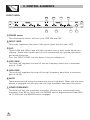
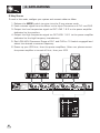
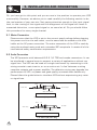
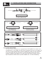
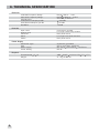
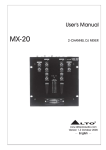
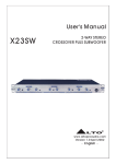
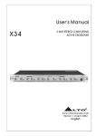
R
LTO
User's Manual
X23
2-WAY STEREO/3-WAY MONO
ACTIVE CROSSOVER
www.altoproaudio.com
Version 1.0 SEP. 2007
English
IMPORTANT SAFETY INSTRUCTION
CAUTION
RISK OF ELECTRIC SHOCK
DO NOT OPEN
TO REDUCE THE RISK OF ELECTRIC SHOCK
PLEASE DO NOT REMOVE THE COVER OR
THE BACK PANEL OF THIS EQUIPMENT.
THERE ARE NO PARTS NEEDED BY USER
INSIDE THE EQUIPMENT. FOR SERVICE,
PLEASE CONTACT QUALIFIED SERVICE
CENTERS.
WARNING
To reduce the risk of electric shock
and fire, do not expose this equipment
to moisture or rain.
Dispose of this product should
not be placed in municipal waste
and should be separate collection.
11. Move this Equipment only with a cart,
stand, tripod, or bracket,
This symbol, wherever used, alerts you to the
specified by the
presence of un-insulated and dangerous voltages
manufacturer, or
within the product enclosure. These are voltages that
sold with the
may be sufficient to constitute the risk of electric
Equipment. When
shock or death.
a cart is used, use
This symbol, wherever used, alerts you to
caution when
important operating and maintenance instructions.
moving the cart /
Please read.
equipment
Protective Ground Terminal
combination to
AC mains (Alternating Current)
avoid possible
Hazardous Live Terminal
injury from tip-over.
ON: Denotes the product is turned on.
12. Permanent hearing loss may be caused by
OFF: Denotes the product is turned off.
exposure to \ extremely high noise levels.
CAUTION
The US. Government's Occupational Safety
Describes precautions that should be observed to
and Health Administration (OSHA) has
prevent damage to the product.
specified the permissible exposure to noise
1. Read this Manual carefully before operation.
level.
2. Keep this Manual in a safe place.
These are shown in the following chart:
3. Be aware of all warnings reported
with this symbol.
HOURS X DAY SPL EXAMPLE
4. Keep this Equipment away from water and
90 Small gig
8
moisture.
92 train
6
5. Clean it only with dry cloth. Do not use
95 Subway train
4
solvent or other chemicals.
97 High level desktop monitors
3
6. Do not damp or cover any cooling opening.
100 Classic music concert
2
Install the equipment only in accordance with
102
1,5
the Manufacturer's instructions.
105
1
7. Power Cords are designed for your safety. Do
110
0,5
not remove Ground connections! If the plug
0,25 or less 115 Rock concert
does not fit your AC outlet, seek advice from
a qualified electrician. Protect the power
According to OSHA, an exposure to high SPL in
cord and plug from any physical stress to
excess of these limits may result in the loss of
avoid risk of electric shock. Do not place
heat. To avoid the potential damage of heat, it is
heavy objects on the power cord. This could
cause electric shock or fire.
recommended that Personnel exposed to
equipment capable of generating high SPL use
8. Unplug this equipment when unused for long
hearing protection while such equipment is
periods of time or during a storm.
under operation.
9. Refer all service to qualified service personnel
The apparatus shall be connected to a mains
only. Do not perform any servicing other than
those instructions contained within the
socket outlet with a protective earthing
User's Manual.
connection.
10. To prevent fire and damage to the product,
use only the recommended fuse type as
indicated in this manual. Do not short-circuit
the fuse holder. Before replacing the fuse,
make sure that the product is OFF and
disconnected from the AC outlet.
The mains plug or an appliance coupler is used
as the disconnect device, the disconnect device
shall remain readily operable.
IN THIS MANUAL:
1.
2.
3.
4.
5.
6.
7.
INTRODUCTION..........................................................................1
FEATURES.................................................................................1
CONTROL ELEMENTS.................................................................2
APPLICATION.............................................................................4
INSTALLATION & CONNECTION....................................................6
TECHNICAL SPECIFICATIONS........................................................8
WARRANTY................................................................................9
1. INTRODUCTION
Thank you for your purchasing the
LTO products X23 Active Crossover.
It is just one of the many LTO products that a talented, multinational Team
of Audio Engineers and Musicians have developed with their great passion for
Music. The X23 Active Crossover is an ideal crossover and used universally in
most small and large PA systems, recording studio monitors, DJ setups,
commercial installations and live concerts. It is not only adaptable in mounting
to different sound systems, but also it has many developed features. For
example, Clip LED Indicators, Mute switches for all frequencies output, CD
Boost and Phase Inversion. The X23 Active Crossover is a single rack unit, dual
channels electronic crossover, which is able to operate as the 2-way stereo
and 3-way mono speaker systems.
Enjoy your X23 and make sure to read this Manual carefully before operation!
2. FEATURES
Mountable in a 19" rack unit(1U)
Clip LED indicators
Mute switches used to mute the output signal of each frequencies range
XLR balanced and connectors for inputs and outputs
Excellent audio performance and low noise interference
1/4" TRS
Phase inversion compensates for corresponding frequencies cancellation in
some field
CD Boost compensates power loss during the long distance transmission
1
SP
OT
L
IG
3. CONTROL ELEMENTS
HT
FRONT PANEL
3
LOW
CLIP
HIGH
LOW
CLIP
4
7
X23
HIGH
CHANNEL 1
0
5
CHANNEL 2
0
170
0
300
0
0
170
300
0
R
LTO
OFF
6
INPUT LEVEL
(INPUT LEVEL)
OFF
6
LOW GAIN
(LOW GAIN)
MUTE
90
700
90
80
1K
XOVER FREQ
(XOVER FREQ)
1
10
RANGE
OFF
6
HIGH GAIN
MUTE
6
OFF
INPUT LEVEL
2
OFF
6
MUTE
700
80
1K
XOVER FREQ
(XOVER FREQ)
LOW GAIN
(MID GAIN)
6
ON
1
10
RANGE
OFF
OFF
6
2-WAY STEREO
3-WAY MONO
ACTIVE CROSSOVER
MUTE
2W- STEREO
(3W- MONO)
HIGH GAIN
(HIGH GAIN)
6
POWER
1
1 POWER switch
This illuminated switch will turn your X23 ON and OFF
2 INPUT LEVEL
This knob regulates the level of the input signal fed into your X23.
3 CLIP
These LOW and HIGH Leds will light up when one or both audio bands are
clipping. These leds should light up only occasionally for optimal operation
and avoid distortion.
Turn the INPUT LEVEL control down if they are always on.
4 LOW GAIN
This knob will regulate the level of the low frequency band with a maximum
gain of+6 dB.
5 HIGH GAIN
This knob will regulate the level of the high frequency band with a maximum
gain of+6 dB.
6 MUTE
These switches will mute the respective low or high band. When the low-mute
switch is engaged you will only hear the high frequency band and vice versa.
7 XOVER FREQUENCY
This knob will set the crossover frequency. You can vary continuously such
frequency from 80 to 1kHz with the RANGE switch depressed and from 800
to 10 kHz with the RANGE switch engaged.
2
SP
OT
L
IG
3. CONTROL ELEMENTS
HT
REAR PANEL
13
13
PUSH
PUSH
STEREO MONO
Rated Power Consumption 8.5W
FUSE:
210-240V: T100mAL 250VAC
95-120V: 200mA 250VAC
REPLACE FUSE WITH CORRECT
TYPE ONLY
NEW
CD
BOOST MODE
HIGH
PHASE
2
TIDE
3
NEW
HIGH
PHASE
1
CD
BOOST
2
TIDE
3
1
2WAY- STEREO
/ (3WAY- MONO)
A101
DESIGNED IN ITALY
MADE IN CHINA
8
HIGH OUT 2 / (HIGH OUT)
LOW OUT 2 / (MID OUT)
INPUT 2 / (NOT USED)
HIGH OUT 1 / (NOT USED)
CHANNEL 2
11
LOW OUT1 / (LOW OUT)
INPUT 1 / (INPUT)
CHANNEL 1
12
9
10
12
9
8 AC Inlet and Fuse holder
Standard IEC receptacle. Connect your X23 to the AC with the supplied AC
power cord. Before powering up your X23 for the first time, make certain
the stated power requirement of the unit matches the voltage supplied by the
AC socket.
If the fuse blows, replaced with a fuse of the correct type only.
9 INPUT 1 & 2
Lettering for 3-way mono operation is into brackets. Standard operation is
2-way stereo. You can feed balanced and unbalanced signals into your X23
through these connectors. For 2-way stereo operation the MODE switch
must be disengaged. If the MODE switch is engaged, you will operate in
3-way MONO mode. In such case only use INPUT ONE to feed the signal
into your X23. Do not use INPUT 2.
10 CHANNEL 1 HIGH AND LOW OUT
In 2-way stereo operation (MODE switch disengaged), connect these outputs
respectively to the low frequency and high frequency power amplifiers. In
3-way mono operation (MODE switch engaged) connect LOW OUT to the low
frequency power amplifier. Do not use the HIGH OUT OUTPUT.
11 CHANNEL 2 HIGH AND LOW OUT
In 2-way stereo operation (MODE switch disengaged), connect these outputs
respectively to the low frequency and high frequency power amplifiers. In
3-way mono operation (MODE switch engaged) connect LOW OUT to the
middle frequency power amplifier and HIGH OUT to the high frequency power
amplifier.
12 CD BOOST
High frequencies, even when reproduced by good quality compression drivers
and horns suffer of fast decay. Therefore the sound pressure level of high
frequencies is affected by the distance of the horn from the Audience. With
some large Live applications it may be necessary to boost the high frequencies
to compensate such loss. CD boost stands for Constant Directivity Boost.
Engaging this switch you will produce a boost of 3 dB at 3,5 kHz and then
6 dB x oct up to 22.5 kHz.
13 HIGH PHASE
This switch will produce a phase inversion of 180 to compensate for phase
cancellation.
3
3.
ELEMENTS
4. CONTROL
APPLICATIONS
2-Way Stereo
To work in this mode, configure your system and connect cables as follow:
1. Release the MODE switch to enter into the 2-way stereo mode.
2. Feed a stereo signal from the Mixer to the Input Connectors of CH1 and CH2.
3. Output the Low frequencies signal via OUT LOW 1 & 2 to the power amplifier
dedicated to the woofers.
4. Output the High frequencies signal via OUT HIGH 1 & 2 to the power amplifier
dedicated to the high frequency transducers.
5. Set LOW-HIGH Crossover Range of CH1 and CH2 to 10 (switch engaged) and
select the desired crossover frequency.
6. Power up your X23 first, then the power amplifiers. After use, please ensure
the power amplifier is turned off first, then your X23.
R
R
LTO
LTO
MAC 2.4
MAC 2.4
Stereo Power Amplifier
ON
CH1
POWER
Stereo Power Amplifier
ON
CH2
CH1
POWER
PROT
CH2
PROT
CLIP
CLIP
SIG
SIG
OFF
OFF
POWER
POWER
PUSH
PUSH
STEREO MONO
Rated Power Consumption 8.5W
FUSE:
210-240V: T100mAL 250VAC
95-120V: 200mA 250VAC
REPLACE FUSE WITH CORRECT
TYPE ONLY
NEW
CD
BOOST MODE
HIGH
PHASE
2
TIDE
3
NEW
CD
BOOST
HIGH
PHASE
1
2
TIDE
3
1
2WAY- STEREO
/ (3WAY- MONO)
A101
4
DESIGNED IN ITALY
MADE IN CHINA
HIGH OUT 2 / (HIGH OUT)
LOW OUT 2 / (MID OUT)
CHANNEL 2
INPUT 2 / (NOT USED)
HIGH OUT 1 / (NOT USED)
LOW OUT1 / (LOW OUT)
CHANNEL 1
INPUT 1 / (INPUT)
3.
ELEMENTS
4. CONTROL
APPLICATIONS
3-WAY MONO
To work in this mode, configure your system and connect cables as follow:
1. Press the MODE switch to enter into the 3-way mono mode.
2. Feed a mono signal from the Mixer to the input connector of CH1.
3. Output the Low frequencies signal via OUT LOW 1 to the power amplifier
dedicated to the woofers.
4. Output the Mid frequencies signal via OUT LOW 2 to the power amplifier
dedicated to the midrange.
5. Output the High frequencies signal via OUT HIGH 2 to the power amplifier
dedicated to the high frequency transducer.
6. Set LOW-HIGH Crossover Range of channel1 to x1 (switch disengaged) and
select the desired crossover frequency. This channel will crossover low and
mid frequencies.
7. Set LOW-HIGH Crossover Range of channel 2 to x10 (switch engaged) and
select the desired crossover frequency. This channel will crossover mid and
high frequencies.
8. Power up your X23 first, then the power amplifiers. After use, please ensure
the power amplifier is turned off first, then your X23.
LOW
HIGH
R
LTO
MAC 2.4
Stereo Power Amplifier
ON
CH1
POWER
CH2
PROT
CLIP
SIG
OFF
POWER
MID
R
LTO
MAC 2.4
Stereo Power Amplifier
ON
CH1
POWER
CH2
PROT
CLIP
SIG
OFF
POWER
PUSH
PUSH
STEREO MONO
Rated Power Consumption 8.5W
FUSE:
210-240V: T100mAL 250VAC
95-120V: 200mA 250VAC
REPLACE FUSE WITH CORRECT
TYPE ONLY
NEW
CD
BOOST MODE
HIGH
PHASE
2
TIDE
3
NEW
CD
BOOST
HIGH
PHASE
1
2
TIDE
3
1
2WAY- STEREO
/ (3WAY- MONO)
A101
DESIGNED IN ITALY
MADE IN CHINA
HIGH OUT 2 / (HIGH OUT)
LOW OUT 2 / (MID OUT)
CHANNEL 2
INPUT 2 / (NOT USED)
HIGH OUT 1 / (NOT USED)
LOW OUT1 / (LOW OUT)
INPUT 1 / (INPUT)
CHANNEL 1
5
5. INSTALLATION AND CONNECTION
Ok, you have got to this point and you are now in the position to operate your X23
successfully. However, we advise you to read carefully the following section to be
the real master of your own mix. Not paying attention enough to the input signal
level, to the routing of the signal and the assignment of the signal will result in
unwanted distortion, a corrupted signal or no sound at all. So you should follow
this procedure for every single channel:
5.1 Mains Connection
Please ensure that the X23 is set to the correct supply voltage before plugging
the power cord into the wall outlet, use the same fuse as marked on the fuse
holder at the AC power connection. The mains connection of the X23 is made by
using the enclosed mains cord and a standard IEC receptacle. It meets all of the
international safety certification requirements.
5.2 Audio Connection
The X23 presents with balanced XLR & 1/4" TRS and combo connectors. It can
be interfaced in several ways to support a variety of applications without any
signal loss. The X23 can be used on a single instrument by connecting to the
mixing console's main inserts, or on an entire mix "in-line" between a mixing
console's outputs and a power amplifier. The defective wiring may degrade the
performance of X23, so please use good quality screened audio cables only.
Please follow the guide below to interface X23 without experiencing any noise
or signal loss.
Sleeve
Tip
Ring
Ring=Right Signal
Strain Clamp
Tip=Left Signal
Sleeve=Ground/Screen
Use for Headphone
1/4" Stereo (TRS) Jack Plug
Sleeve
Tip
Tip=Signal
Strain Clamp
Sleeve=Ground/Screen
Use for Mono Line In, Mono 1/4" Jack Plugs
1/4" Mono (TS) Jack Plug
6
3.
ELEMENTS
5. CONTROL
INSTALLATION
AND CONNECTION
Sleeve
Ring=Return Signal
Tip
Ring
Strain Clamp
Tip=Send Signal
Sleeve=Ground/Screen
Use for Insert Points
1/4" Stereo (TRS) Jack Plug
2=Hot(+)
2
3
1
2=Hot(+)
1=Ground/Screen
2
3
1
1=Ground/Screen
3=Cold(-)
3=Cold(-)
Use for Balanced Mic Inputs
(For unbalanced use, connect pin 1 to 3)
Use for Main output
(For unbalanced use, leave pin3 unconnected)
3-pin XLR Male Plug
3-pin XLR Line Socket
(seen from soldering side)
(seen from soldering side)
SLEEVE TIP
TIP RING SLEEVE
Tip
Ring
Sleeve
Tip (Send)
Sleeve
Tip (Return)
Sleeve
SLEEVE RING TIP
1
2 (Send)
1
3
2
Tip
Ring
Sleeve
2
1
2 (Return)
3
1
TIP RING SLEEVE
3
3
Tip
Ring
Sleeve
Centre (Send)
Screen
Centre (Return)
Screen
TIP RING SLEEVE
Insert Leads
5.3. RACK MOUNTING
The most secure mounting is on a universal rack shelf available from various rack
manufacturers or your Dealer. The X23 Active Crossover fits into one standard 19"
rack unit of space. Please allow at lease an additional 4" depth for the connectors
on the rear panel. Be sure that there is enough air space around the unit for
sufficient ventilation and please do not place your X23 Active Crossover close to
high temperature devices such as power amplifiers etc. to avoid overheating.
7
6. TECHNICAL SPECIFICATION
Electrical
LOW-MID Frequency Range
MID-HIGH Frequency Range
HUM & Noise
LOW Section (Output@0 dB)
HIGH Section(Output @0 dB)
S/N Ratio
Range 1 80 Hz - 1 kHz
Range 10 800 Hz - 10 kHz
AV=0 dB, fc=800 Hz
-106 dBu
-97 dBu
118 dB
Input Level
Output Level
CD Boost
Mute
Phase
Continuously variable
Low, high continuously variable
Rear panel switch
Low, high front panel switches
Rear panel switch
Controls
Power Supply
Connector type
Type
Mains supply
Power Rating
3-pole IEC, grounded
Servo controlled, stabilized
95-120 V /210-240 V , 60-50 Hz
8.5 W
Physical
Dimensions(W
Weight
8
D
H)
483 194.5 44 mm (19" 7.7" 1.7")
3.1 Kg (6.84 lb)
7. WARRANTY
1. WARRANTY REGISTRATION CARD
To obtain Warranty Service, the buyer should first fill out and return the enclosed
Warranty Registration Card within 10 days of the Purchase Date.
All the information presented in this Warranty Registration Card gives the
manufacturer a better understanding of the sales status, so as to provide a
more effective and efficient after-sales warranty service. Please fill out all the
information carefully and genuinely, miswriting or absence of this card will void
your warranty service.
2. RETURN NOTICE
2.1 In case of return for any warranty service, please make sure that the
product is well packed in its original shipping carton, and it can protect your
unit from any other extra damage.
2.2 Please provide a copy of your sales receipt or other proof of purchase with
the returned machine, and give detail information about your return address
and contact telephone number.
2.3 A brief description of the defect will be appreciated.
2.4 Please prepay all the costs involved in the return shipping, handling and
insurance.
3. TERMS AND CONDITIONS
3.1 LTO warrants that this product will be free from any defects in materials
and/or workmanship for a period of 1 year from the purchase date if you
have completed the Warranty Registration Card in time.
3.2 The warranty service is only available to the original consumer, who purchased
this product directly from the retail dealer, and it can not be transferred.
3.3 During the warranty service, LTO may repair or replace this product at its
own option at no charge to you for parts or for labor in accordance with the
right side of this limited warranty.
3.4 This warranty does not apply to the damages to this product that occurred
as the following conditions:
Instead of operating in accordance with the user's manual thoroughly, any abuse
or misuse of this product.
Normal tear and wear.
The product has been altered or modified in any way.
Damage which may have been caused either directly or indirectly by another
product / force / etc.
Abnormal service or repairing by anyone other than the qualified personnel or
technician.
And in such cases, all the expenses will be charged to the buyer.
3.5 In no event shall LTO be liable for any incidental or consequential damages.
Some states do not allow the exclusion or limitation of incidental or
consequential damages, so the above exclusion or limitation may not apply to
you.
3.6 This warranty gives you the specific rights, and these rights are compatible
with the state laws, you may also have other statutory rights that may vary
from state to state.
9
SEIKAKU TECHNICAL GROUP LIMITED
NO. 1, Lane 17, Sec. 2, Han Shi West Road, Taichung 40151, Taiwan
http://www.altoproaudio.com Tel: 886-4-22313737
email: [email protected] Fax: 886-4-22346757
All rights reserved to ALTO. All features and content might be changed
without prior notice. Any photocopy, translation, or reproduction of part of this
manual without written permission is forbidden. Copyright c 2007 Seikaku Group