1
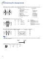
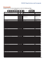
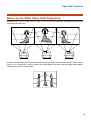
Connecting Pin Assignments
DVI digital Terminal (INPUT 3)
24
17
8
16
1
9
Pin No.
1
2
3
4
5
6
7
8
9
10
11
12
13
14
15
16
Signal
T.M.D.S. Data 2–
T.M.D.S. Data 2+
T.M.D.S. Data 2 Shield
Not connected
Not connected
DDC Clock
DDC Data
Not connected
T.M.D.S. Data 1–
T.M.D.S. Data 1+
T.M.D.S. Data 1 Shield
Not connected
Not connected
+5 V Power
Ground
Hot Plug Detect
Pin No.
17
18
19
20
21
22
23
24
Signal
T.M.D.S. Data 0–
T.M.D.S. Data 0+
T.M.D.S. Data 0 Shield
Not connected
Not connected
T.M.D.S. Clock Shield
T.M.D.S. Clock+
T.M.D.S. Clock–
11