1
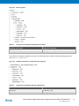
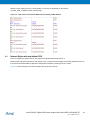
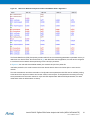
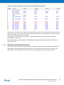
APPLICATION NOTE
Atmel AT02597: ZigBee PRO Packet Analysis with Sniffer
Atmel MCU Wireless
Features
•
ZigBee® Protocol Analysis with Industry-standard sniffing tools such as Luxoft’s
BitCatcher, Wireshark and Perytons
•
Provides instructions and examples on using the sniffer to analyze and debug
network behavior
Description
Monitoring Wireless network activity in ZigBee networks is essential in understanding
the behavior and traffic patterns of the network. Network Protocol analyzers are
powerful and flexible tools that aid debugging during ZigBee-based application
development.
This Application Note describes how to configure and use supported sniffing tools
along with Atmel® MCU-based sniffer hardware platforms.
32210A−WIRELESS−09/2013
Table of Contents
1. Overview .............................................................................................. 3 1.1 The Wireshark Capture Interface from Atmel Gallery........................................ 3 1.1.1 Setup Information ............................................................................... 4 1.2 BitCatcher ......................................................................................................... 5 1.2.1 Setup Information ............................................................................... 5 1.3 Perytons Network Analyser ............................................................................... 6 2. Sniffer Capture Session Setup ............................................................. 7 2.1 Wireshark Capture Interface ............................................................................. 7 2.2 BitCatcher ......................................................................................................... 8 2.3 Perytons Network Analyser ............................................................................. 10 3. Configuring Sniffer Preferences ......................................................... 12 3.1 Wireshark Capture Interface ........................................................................... 12 3.2 BitCatcher ....................................................................................................... 14 3.3 Perytons Network Analyzer ............................................................................. 15 4. Analyzing Data Traffic in ZigBee PRO Networks ............................... 17 4.1 ZigBee Frame Format Overview ..................................................................... 17 4.2 MAC Association ............................................................................................. 17 4.3 Network Rejoin with and without PDS ............................................................. 20 4.4 Self-Leave and Parent-Induced Leave ............................................................ 22 4.5 Network Link Status Frame ............................................................................. 23 4.6 Multicast .......................................................................................................... 24 4.7 Fragmentation ................................................................................................. 25 4.8 Service Discovery ........................................................................................... 26 4.9 Tunneling in Secure Networks ........................................................................ 26 5. Analyzing Data Traffic in ZigBee PRO Public Profile Networks ......... 28 5.1 ZigBee Home Automation ............................................................................... 28 5.1.1 Service Discovery ............................................................................. 28 5.1.2 Attribute Reporting ............................................................................ 28 5.1.3 Commands ....................................................................................... 29 5.1.4 Security ….. ...................................................................................... 29 5.2 ZigBee Light Link ............................................................................................ 29 5.2.1 Touchlinking ...................................................................................... 29 5.2.2 Cluster Commands ........................................................................... 30 5.2.3 Security ….. ...................................................................................... 30 5.3 ZigBee Smart Energy ...................................................................................... 30 6. Example Application Scenarios.......................................................... 31 6.1 PAN Same Channel Co-Existence .................................................................. 31 6.2 End-to-End Establishment of Application Link Key ......................................... 31 6.3 ZLL – ZHA Interoperability .............................................................................. 32 7. References ......................................................................................... 33 8. Revision History ................................................................................. 34 Atmel AT02597: ZigBee PRO Packet Analysis with Sniffer [APPLICATION NOTE]
32210A−WIRELESS−09/2013
2
1.
Overview
In ZigBee networking, a sniffing tool is important during development and testing for the capture and analysis of frames
exchanged in the network. It is more significant in networks that have ZigBee products from different vendors to test and
verify that they inter-operate with one another.
The sniffing tool shall be capable of real-time capture of frame formats supported by the ZigBee protocol and the IEEE®
802.15.4 standard. The sniffer shall also provide parsed information of different fields and sub-fields of the frame, which
shall aid the user in quick analysis.
A visual view of the network topology, time stamping, multi-channel capture and saving of the capture files are some of
the features of sniffers that the user can benefit from, to gain a complete picture of the wireless environment that is
being monitored.
The Wireless network sniffer environment is setup by running one of the network protocol analyzers in Figure 1-1 on the
PC.
Figure 1-1. Supported ZigBee Network Protocol Analyzers.
To start capturing frames on an IEEE 802.15.4 channel, one should have a sniffer hardware tool running a sniffer
firmware, plugged into the PC.
Figure 1-2. Supported Sniffer Hardware Platforms.
The RZUSBSTICK and the deRFusb23E06 [10] can be used to sniff IEEE 802.15.4 2.4GHz operating channels.
The deRFusb13E06 [10] can be used as an IEEE 802.15.4 sub-GHz sniffer.
1.1
The Wireshark Capture Interface from Atmel Gallery
A simple Capture Interface that can be used to create capture sessions for IEEE 802.15.4 2.4GHz channels is available
for download from Atmel Gallery.
Apart from the RZUSBSTICK, this interface supports the RZ600-RF231 radio board [2] as a sniffer hardware platform.
Atmel AT02597: ZigBee PRO Packet Analysis with Sniffer [APPLICATION NOTE]
32210A−WIRELESS−09/2013
3
1.1.1
Setup Information
To setup the capture session using Wireshark, download the Atmel Wireshark Interface from Atmel Gallery [7].
Wireshark version Wireshark-win32-1.8.0 or lesser shall be installed on the PC [8].
Figure 1-3. Atmel Wireshark Interface in Atmel Gallery.
•
The package is installed in directory \Atmel\AtmelWiresharkFirmware
•
Follow the instructions in the Readme_Important_Atmel_Wireshark_Sniffer_Interface.txt to
complete the setup procedure
•
The sniffer firmware to be flashed on the respective hardware platforms, RZUSBSTICK and RZ600 are
provided as images (Wireshark_Sniffer_Raven.hex and Wireshark_Sniffer_RZ600.elf) in the
package
•
Refer to [4] and [2] for programming instructions
Caution:
For the RZUSBTICK, the fuse settings shall be:
Extended: 0xFB, High: 0x91, Low: 0xDE
•
•
This version of the Wireshark capture interface (v1.0) does not support sub-GHz sniffer tools
The USB drivers available with the package support Windows® XP/2000/7 and are automatically loaded to
Windows by the installer.
Chapter 2 provides further information on setting up a capture session for the Wireshark Interface.
Atmel AT02597: ZigBee PRO Packet Analysis with Sniffer [APPLICATION NOTE]
32210A−WIRELESS−09/2013
4
1.2
BitCatcher
Luxoft BitCatcher ZigBee Network Analyze tool is a simple and flexible protocol analyzer that can be used to analyze
standard IEEE 802.15.4 and ZigBee frames using Atmel hardware sniffing tools in the sub-GHz and 2.4GHz frequency
bands.
1.2.1
Setup Information
The sniffer PC tool can be downloaded from [3].
The package also comes with the firmware files and drivers for the supported sniffer hardware:
•
•
Atmel AVR® RZUSBSTICK
Dresden Elektronik deRFusb-23E00 (2.4GHz) and deRFusb-13E00 (Sub-GHz)
Once installed, sniffer device can be configured for use with the sniffer PC tool as below.
•
•
Plug in the sniffer hardware (e.g.: RZUSBSTICK) to a free USB port in the PC
Flash the sniffer firmware image to the MCU on the sniffer hardware, if not pre-programmed
Caution:
For the RZUSBTICK, the fuse settings shall be:
Extended: 0xFB, High: 0x91, Low: 0xDE
•
The firmware images for the RZUSBSTICK and the deRFUSB is available as .hex files in the directory
\embedded inside the BitCatcher package
•
Un-plug and plug the device into the USB port once again. Install the driver provided in the sniffer package
when prompted for
•
•
The sniffer drivers are available in the directory \driver inside the BitCatcher package
After driver installation, the device will be listed in the Windows Device Manager as shown in Figure 1-4
Figure 1-4. Sniffer Devices Listing in Windows Device Manager.
Atmel AT02597: ZigBee PRO Packet Analysis with Sniffer [APPLICATION NOTE]
32210A−WIRELESS−09/2013
5
1.3
Perytons Network Analyzer
The Perytons Analyzer is a powerful sniffing tool with support for Atmel sniffer hardware platforms for both 2.4GHz and
sub-GHz IEEE 802.15.4 bands. This application note gives only a brief overview of its features and analysis of data
captures with the Perytons Network Analyzer. Further information can be found at [9].
Atmel AT02597: ZigBee PRO Packet Analysis with Sniffer [APPLICATION NOTE]
32210A−WIRELESS−09/2013
6
2.
Sniffer Capture Session Setup
This chapter shows the user how to setup a sniffer capture session after the installation of the hardware driver and the
sniffer tool in the PC has been done successfully.
2.1
Wireshark Capture Interface
•
Open Wireshark_Sniffer_Interface.exe from
\Program Files\Atmel\AtmelWiresharkFirmware
•
From the Sniffer Port column, select the Sniffer port number and click Open as shown in Figure 2-1
Figure 2-1. COM Port Selection.
•
As the Sniffer Capture interface supports 2.4GHz channels, the user can select a channel from Channel 11 to
Channel 26
•
After the channel is set, click Start to begin the capture session as shown in Figure 2-2. A Wireshark instance
will be invoked automatically
Atmel AT02597: ZigBee PRO Packet Analysis with Sniffer [APPLICATION NOTE]
32210A−WIRELESS−09/2013
7
Figure 2-2. Starting a Sniffer Capture Session.
•
2.2
After the capture session is complete, the user can save the capture file for further analysis
BitCatcher
•
Open BitCatcher and add a new sniffer device as shown in Figure 2-3 with the port settings in Figure 2-4
Figure 2-3. Adding a New Sniffer Device.
•
It is possible to edit or remove the connection using the same menu
Atmel AT02597: ZigBee PRO Packet Analysis with Sniffer [APPLICATION NOTE]
32210A−WIRELESS−09/2013
8
Figure 2-4. Port Settings.
•
Once the device is created, it will appear in the device drop-down menu in BitCatcher and shall be selected as
shown below. After device selection, the connect/Disconnect button shall be pressed to begin or end the
usage of the sniffer hardware with BitCatcher
Figure 2-5. Device Selection.
•
After the device connection with BitCatcher is established, the user can configure the Channel and Channel
pages supported. Standard IEEE 802.15.4 channels are supported in the 2.4GHz, 868 and 915MHz frequency
bands
•
Supported Channels in the 2.4GHz bands are from Channel 11 to channel 26 as per formula,
Fc = 2405 + 5 (k - 11) in [MHz], for k = 11, 12... 26
where k is the channel number.
•
Channel 0 is for 868MHz operation and Channels 1 to 10 for 915MHz band. IEEE 802.15.4 -2006 specified
channel pages 0, 2 and 5 are supported
•
The Data capture session can be started or stopped using the Play Button in BitCatcher
Atmel AT02597: ZigBee PRO Packet Analysis with Sniffer [APPLICATION NOTE]
32210A−WIRELESS−09/2013
9
Figure 2-6. Starting the Data Capture Session.
•
BitCatcher allows users to save the sniffer capture data in the form of .dcf files and it is also possible to open
sniffer logs created using other sniffing tools, if the logs are in the .dcf format
File->Open log/Save log options serve these purposes.
2.3
Perytons Network Analyzer
The Data capture session in Perytons Network Analyzer can be started using the Data Capture button as shown
in Figure 2-7.
Figure 2-7. Starting the Data Capture Session.
Before capture is started, it shall be ensured that the hardware is detected by the sniffer tool and the settings are as
per Figure 2-8.
Atmel AT02597: ZigBee PRO Packet Analysis with Sniffer [APPLICATION NOTE]
32210A−WIRELESS−09/2013
10
Figure 2-8. Configuring the Capture Parameters.
The user can save the capture file using the Save & Continue option shown in Figure 2-8.
Atmel AT02597: ZigBee PRO Packet Analysis with Sniffer [APPLICATION NOTE]
32210A−WIRELESS−09/2013
11
3.
Configuring Sniffer Preferences
For easier viewing and analysis, sniffers GUIs provide multiple filtering options. With the appropriate settings, a
complete snapshot of the wireless network can be obtained. This chapter provides information on configuring such
preferences in the sniffer GUI.
3.1
Wireshark Capture Interface
•
Protocols: Wireshark automatically identifies the protocol in use, as all supported protocols are enabled by
default, as can be seen in menu option Analyze -> Enabled Protocols. The user can enable or disable
protocols as per requirement using this option
•
Security: It is possible to monitor encrypted ZigBee network data by entering the NWK security key used in
the network. Use menu option Edit -> Preferences -> Protocols -> ZigBee NWK as shown in Figure 3-1
Figure 3-1. Security Preferences in Wireshark
The security level shall be set as per the ZigBee specification, Table 3-1 is taken from the ZigBee specification
document and lists the supported security levels.
Atmel AT02597: ZigBee PRO Packet Analysis with Sniffer [APPLICATION NOTE]
32210A−WIRELESS−09/2013
12
Table 3-1.
Security Levels – NWK and APS – ZigBee Specification.
Security level
identifier
Security level subfield (Table 4.24)
Security attributes
Data encryption
Frame integrity (length M of MIC,
in number of octets)
0x00
‘000’
None
OFF
NO (M = 0)
0x01
‘001’
MIC-32
OFF
YES (M = 4)
0x02
‘010’
MIC-64
OFF
YES = (M = 8)
0x03
‘011’
MIC-128
OFF
YES (M = 16)
0x04
‘100’
ENC
ON
NO (M = 0)
0x05
‘101’
ENC-MIC-32
ON
YES (M = 4)
0x06
‘110’
ENC-MIC-64
ON
YES = (M = 8)
0x07
‘111’
ENC-MIC-128
ON
YES (M = 16)
It is possible to add multiple keys, edit or remove existing keys as shown in Figure 3-2.
Example:
In a ZigBee network using security in the APS layer, a device joining the network establishes a link key
with the Trust Center. In order to view all APS transactions for this link such as the APS Transport Key
command, the Trust Center link key needs to be added to the sniffer preferences.
Figure 3-2. Security Key Entries.
•
User Interface Options: It is possible to customize viewing options in the Wireshark interface
•
Arrange the layout of the panels from Edit -> Preferences -> Layout
•
Add Columns to the packet display pane (e.g.: HW src addr) from Edit -> Preferences -> Columns
•
Colorize frame formats (e.g.: NWK Link Status Frames) from View -> Coloring Rules
•
Apply Filters to display frames based on chosen fields in a frame by right-clicking on the field and using
option Apply as Filter
Atmel AT02597: ZigBee PRO Packet Analysis with Sniffer [APPLICATION NOTE]
32210A−WIRELESS−09/2013
13
Figure 3-3. Wireshark Capture Screen Layout.
3.2
BitCatcher
•
Protocols: By default, BitCatcher is automatically able to parse the following protocol packets:
•
IEEE 802.15.4 MAC
•
ZigBee PRO (Network, ZDO and APS layers)
•
ZigBee Public Profiles such as ZigBee Smart Energy, Home Automation, and Light Link
It is not possible to explicitly disable any of the above protocols in BitCatcher, although it is possible to enable
or disable packet views of various ZigBee PRO layers (NWK, APS and ZCL).
This configuration can be done using menu option Window -> Sniffer -> Preferences ->Layers
•
Security: It is possible to monitor encrypted ZigBee network data by entering the NWK security key used in
the network. Use menu option Window -> Sniffer -> Preferences -> Core security as shown in Figure 3-4
Figure 3-4. Security Preferences in BitCatcher.
Atmel AT02597: ZigBee PRO Packet Analysis with Sniffer [APPLICATION NOTE]
32210A−WIRELESS−09/2013
14
The security level shall be set as per the ZigBee specification, Table 3-1 is taken from the ZigBee specification
document and lists the supported security levels.
ZigBee Light Link (ZLL) security keys used for inter-PAN data exchange can also be configured in this sniffer using
menu option Window -> Sniffer -> Preferences -> ZLL security.
It is possible to add multiple keys, edit or remove existing keys as shown in Figure 3-4.
If the key is not added to sniffer, the packets shall not be decrypted and shall be displayed in a turquoise blue color font.
•
3.3
User Interface Options: It is possible to customize viewing options in BitCatcher
•
The default layout of the sniffer provides a snapshot of the packet log, a timeline view as well as a
packet dissector called the Packet view. It is possible to drag and re-arrange the views as per need and
also close views
•
The menu option Window -> Show view can be used to show a view closed by the user
•
Add Columns to the packets log panel (e.g.: HW src addr) by right-clicking on any column in the panel
and selecting the option Manage Columns
•
Packets are colorized depending on the layer at which they are formed and sent out (NWK, APS, and
MAC).
Apply Filters to display frames based on chosen fields in a frame by using menu option Window ->
Preferences -> Filters
Perytons Network Analyzer
•
Protocols: Perytons supports the following protocols:
•
IEEE 802.15.4 MAC
•
ZigBee PRO (Network, ZDO and APS layers)
•
ZigBee Public Profiles such as ZigBee Smart Energy, Home Automation, and Light Link
The active protocol can be set when the capture session is configured as shown in Figure 2-8.
•
Security: It is possible to monitor encrypted ZigBee network data by entering the NWK security key used in
the network. Use menu option Window -> Sniffer -> Preferences -> Core security as shown in Figure 3-5
Figure 3-5. Security Preferences in Perytons.
Atmel AT02597: ZigBee PRO Packet Analysis with Sniffer [APPLICATION NOTE]
32210A−WIRELESS−09/2013
15
The security level shall be set as per the ZigBee specification, Table 3-1 is taken from the ZigBee specification
document and lists the supported security levels.
•
User Interface Options: It is possible to customize viewing options in Perytons
•
The tool provides different viewing options such as the Time view, Network view, Message view,
Statistics, and Message Tree view. The user can enable or disable views using menu option Windows
•
Add Columns to the packets log panel (e.g.: HW src addr) by right-clicking on any column in the panel
and selecting the option Manage Columns
•
Packets are colorized as per settings in Tools -> Preferences
•
Apply Filters to display frames based on chosen fields in a frame by using menu option Window ->
Preferences -> Filters
Figure 3-6. Perytons Example Capture Window.
Atmel AT02597: ZigBee PRO Packet Analysis with Sniffer [APPLICATION NOTE]
32210A−WIRELESS−09/2013
16
4.
Analyzing Data Traffic in ZigBee PRO Networks
This chapter provides examples of common interaction in ZigBee PRO networks that shall aid the user to look closely
into various fields of the frame and is not aimed at covering all scenarios that fall under ZigBee specification. Explaining
the meaning of all the fields used in a ZigBee frame is outside the scope of this application note and shall be looked up
in the ZigBee specification [6].
All Configuration Server (CS) parameters mentioned in this Application Note can be set from application configuration.h
or at run-time using CS_WriteParameter API. The description of the CS parameters is also present in respective
API_Reference.chm available in the \Documentation folder in the BitCloud® SDK. Information on when the
parameter shall be set (at compile time only, at run-time before network start or at any time) along with parameter
persistence is available in this file.
4.1
ZigBee Frame Format Overview
Figure 4-1 shows the skeletal overview of the ZigBee frame format.
Figure 4-1. Frame Format.
The APS and NWK layer security headers and footers are also shown in the Figure 4-1. ZigBee uses a non-beacon
enabled MAC format with no security in the MAC layer.
4.2
MAC Association
Every node in a ZigBee network has its own unique 64-bit IEEE/MAC address. When a node joins the network for the
first time, a MAC association procedure is performed, following which it obtains a 16-bit network (short) address from
the parent. This short address is used for further communication in the network, to reduce frame overhead.
BitCloud provides a configuration parameter in application called CS_UID which can be used to set the value of the 64bit MAC address of the node during compilation. The following conditions prevail:
•
Setting CS_UID for testing: Any random 64-bit value can be set at compile time in application configuration.h
or at run-time before calling ZDO_StartNetworkReq()
•
Setting CS_UID during production: Commercial usage of ZigBee products require purchase of a block of
IEEE/MAC addresses from IEEE. This can be programmed into an external EEPROM specifically used for this
purpose. In this case, CS_UID can be set to zero during compile-time, BitCloud will attempt to read the value
from the external EEPROM in this case using API, HAL_ReadUid()
Atmel AT02597: ZigBee PRO Packet Analysis with Sniffer [APPLICATION NOTE]
32210A−WIRELESS−09/2013
17
When a node starts up, it does network discovery by performing an active scan over the channels specified in the
CS_CHANNEL_MASK parameter in BitCloud. A beacon request is sent as seen in packet #4 in Figure 4-2.
Upon reception of a beacon request frame, routers and coordinators already present in network automatically respond
with a beacon frame. The joining node filters a potential parent based on the settings in the beacon packet received.
Figure 4-2. Node Joins Network Via MAC Association Using IEEE Address 0x55ULL.
The beacon from the coordinator/router contains the Association Permit subfield, it is set to TRUE if the device is
accepting association to the PAN. A joining node cannot associate to the device if this sub-field is FALSE.
CS_PERMIT_DURATION controls the joining of devices into the network by setting the permit duration.
Figure 4-3. assocPermit Sub-Field in the Beacon Frame.
Example:
Figure 4-4 shows parsed beacon payload that contains information based on which the joining node
chooses a potential parent.
The beacon payload provides information on the ZigBee stack profile used in the network (ZigBee PRO = 0x02),
network protocol version (nwkcProtocolVersion, 0x02 as per ZigBee PRO specification). The router capacity, enddevice capacity and device depth limits the acceptance of children by a parent node.
Atmel AT02597: ZigBee PRO Packet Analysis with Sniffer [APPLICATION NOTE]
32210A−WIRELESS−09/2013
18
Figure 4-4. Beacon Payload.
Table 4-1.
Config. Server Parameters Affecting Beacon Payload.
Capability info sub-field
Config. server parameter
routerCapacity
CS_MAX_CHILDREN_ROUTER_AMOUNT
edCapacity
CS_MAX_CHILDREN_AMOUNT
A joining device indicates its capability information in the MAC association request it sends to its potential parent as
shown in Figure 4-5 and Table 4-2.
Figure 4-5. Capability Information in a MAC Association Request.
Table 4-2.
Config. Server Parameters Affecting Capability Info.
Capability info sub-field
Config. server parameter
deviceType
CS_DEVICE_TYPE
rxOnWhenIdle
CS_RX_ON_WHEN_IDLE
Atmel AT02597: ZigBee PRO Packet Analysis with Sniffer [APPLICATION NOTE]
32210A−WIRELESS−09/2013
19
Without a proper setting of the CS_UID parameter, a node tries to repeatedly join the network
CS_ZDO_JOIN_ATTEMPTS times unsuccessfully.
Figure 4-6. Node Tries to Join Network Without Proper Setting of IEEE Address.
4.3
Network Rejoin with and without PDS
There are multiple join options that can be configured using BitCloud as mentioned in [1].
Network rejoin method is used when a node wishes to join a network with knowledge of networking parameters such as
the network’s extended PANID or application-assigned short address, operating channel or others.
Figure 4-7 shows examples of several successful network rejoin procedures.
Atmel AT02597: ZigBee PRO Packet Analysis with Sniffer [APPLICATION NOTE]
32210A−WIRELESS−09/2013
20
Figure 4-7. Node Joins Network Via Rejoin Procedure with PDS Not Used in Application.
The Persist Data Server (PDS) Component provides useful API to store networking parameters to persistent memory to
retain them over device resets. See section PDS in [1]. With PDS APIs used in application, the node сan be configured
to come back into the network without performing over-the-air rejoin procedure.
In Figure 4-8, the node with short address 0x0001 joins network via rejoin from packet #3.
Just before packet #13, this node is reset and it is seen that the device does not do further rejoin to come into the
network.
The node reset behavior and further restoration of configuration server parameters with PDS can be verified by looking
at the values of the sequence numbers and counter values in various layers. These parameters are among the config.
server parameters and hence are restored on rejoin with PDS implemented. Without PDS implementation, the stack
resets these values to default values on startup.
Atmel AT02597: ZigBee PRO Packet Analysis with Sniffer [APPLICATION NOTE]
32210A−WIRELESS−09/2013
21
Figure 4-8. Node Joins Network Via Rejoin Procedure with PDS Used in Application.
The silent rejoin is very useful when nodes are reset after a battery change, or after a mains-powered network has reset
after a power outage. The nodes come back into the network seamlessly and can route packets, with their networking
tables restored from Persistent memory to RAM.
Packet #9 shows a device announcement frame. This broadcast frame is sent by a device after it has properly
authenticated into the network.
Devices that receive this frame update their network address map tables with the device information obtained in the
device annce frame.
4.4
Self-Leave and Parent-Induced Leave
ZDP Requests are managed by the ZDO layer and can be used for various network control scenarios as detailed in [1].
Network leave can be processed using ZDP requests when a device needs to leave the network on certain events.
Network leave can be self-induced on a node or a node can order another remote node to leave the network.
Atmel AT02597: ZigBee PRO Packet Analysis with Sniffer [APPLICATION NOTE]
32210A−WIRELESS−09/2013
22
Figure 4-9. Self-Leave of Node With Short Address 0x0001 and Extended Address 0x02ULL.
Figure 4-10. Parent Node 0x0000 Sends a ZDP Request Requesting Child 0x0001 to Leave.
It is possible to configure options such as rejoin, removal of children in the leave request.
4.5
Network Link Status Frame
NWK link status frames are sent by routers and coordinator so that neighboring nodes can maintain information on the
link costs required for routing.
Link Status frames are periodically transmitted as one-hop broadcasts. The Link Status list contains the short address
and link cost information of all neighboring nodes as shown in Figure 4-12.
Atmel AT02597: ZigBee PRO Packet Analysis with Sniffer [APPLICATION NOTE]
32210A−WIRELESS−09/2013
23
Figure 4-11. Header Information in a NWK Link Status Frame.
Table 4-3.
4.6
Config. Server Parameters Relevant to NWK Link Status.
Information
Config. server parameter
Neighbor Table size
CS_NEIB_TABLE_SIZE
Number of missed link status frames to remove an entry from
neighbor table
CS_NWK_MAX_LINK_STATUS_FAILURES
Multicast
Broadcasting a message to a group of nodes involves creating a group table entry for a specified end-point and group
ID. Refer to Section 6.4.3 Multicast transmission in [1] for implementation specifics.
Sniffer log, multicast.dcf, shows a multicast transmission from coordinator to Group 1 and end-point 0xF0 in #34.The
network destination address is the group address.
Multicasts do not have APS Acknowledgements and are re-broadcast by all routers (group members and nonmembers) until the radius is exhausted. Figure 4-13 shows the non-member radius which is decremented on every nonmember re-broadcast of the frame.
Atmel AT02597: ZigBee PRO Packet Analysis with Sniffer [APPLICATION NOTE]
32210A−WIRELESS−09/2013
24
Figure 4-12. Multicast Sub-Field – NWK Header.
In response to #34, group member node 0x31BC responds with APL data on end-point 0xF0 whereas node 0x0BDD is
a non-member and so does not respond.
0x0BDD is then added to the group and so responds with APL data on end-point 0xF0 in #59.
4.7
Fragmentation
When APL data packets greater than the maximum size of the APL payload needs to be sent, the stack fragments the
entire data into blocks. The fragmentation concept is explained in Section 6.7 Fragmentation of [1].
Figure 4-13. Fragmentation – Relevant Header Information.
Atmel AT02597: ZigBee PRO Packet Analysis with Sniffer [APPLICATION NOTE]
32210A−WIRELESS−09/2013
25
Figure 4-14. Fragmentation – Example.
As per ZigBee specification, the first fragment is sent with the block number as the total number of blocks comprising
the entire APL data, as seen in Figure 4-14. The subsequent fragments have block numbers starting from 1 onwards up
to maximum transmission window size. The receiving node sends an APS Acknowledgment frame when all blocks in
the transmission window have been received.
Table 4-4.
4.8
Config. Server Parameters Affecting Data Transmission.
Information
Config. server parameter
Single Fragment size
CS_APS_BLOCK_SIZE
Number of fragments /blocks the APL data is split into
CS_APS_MAX_BLOCKS_AMOUNT
Number of blocks to be sent before expecting an APS ACK
CS_APS_MAX_TRANSMISSION_WINDOW_SIZE
Size of a single fragment in fragmented transmission
CS_APS_TX_BLOCK_SIZE
Size of one receive buffer that will hold one fragment of the
data frame.
CS_APS_RX_BLOCK_SIZE
Service Discovery
Service Discovery is the process of collecting information on supported clusters on other devices in the network.
Service discovery uses ZDP requests (with MATCH_DESCRIPTOR_CLID) for every cluster ID supported. Service
discovery requests can be unicast or broadcast and so the response contains the network address of the responder
along with the matched simple descriptor information.
The response contains a match list with the end-points that support the cluster in the request. Service discovery is
explained in further detail in Section 5.1.1.
4.9
Tunneling in Secure Networks
Consider a network wherein a node insecurely joins through a router parent (i.e.) the joining node does not know the
network key prior to join procedure.
In this case, the APS command used to securely communicate the network key from the Trust Center to the newly
joined router is called the APS Tunnel command.
Referring to sniffer log, Transport_key_tunnel.dcf, end-device 0x01LL joins router 0x0000000100000000 from packet
#26. The parent router sends an APS Update Device command to the Trust Center to inform the Trust Center that a
node has joined or left the network.
Figure 4-11 shows the update status of the device, depending on which the Trust Center takes necessary action (i.e.) to
send the network or remove the key and associated security counters for the device.
Atmel AT02597: ZigBee PRO Packet Analysis with Sniffer [APPLICATION NOTE]
32210A−WIRELESS−09/2013
26
Figure 4-15. Status Field in APS Update Device Command.
Trust Center sends the APS Tunnel command frame in #39. The Tunnel command frame will contain the secured frame
to be sent to the destination, in its payload.
#43 shows the APS Transport Key command frame sent from the router parent to the newly joined end-device. It
includes the key sequence number and the active network key. In case the router has joined with a pre-configured
network key, the APS Transport packet would contain key sequence number and the key values as all-zeros.
End-device receives the Transport Key command frame, sets and activates the network key and does a device
announcement to the network.
Atmel AT02597: ZigBee PRO Packet Analysis with Sniffer [APPLICATION NOTE]
32210A−WIRELESS−09/2013
27
5.
Analyzing Data Traffic in ZigBee PRO Public Profile Networks
Networks based on ZigBee PRO Public Profiles such as ZigBee Smart Energy, Home Automation, Light Link employ
specific join, security and data exchange schemes. The implementation details of the reference applications can be
found in [5].
This chapter provides sniffer data analysis of example sniffer logs taken using [5]. The sniffer logs are provided in a zip
package with this application note and this chapter references packet numbers from these logs. The logs are in *.dcf
format and can be viewed in BitCatcher.
5.1
ZigBee Home Automation
The Home Automation (HA) reference application in BitCloud Profile Suite implements six HA device types. The sniffer
log, HA_TC_DL_DS.dcf, demonstrates data exchange between a Trust Center, Dimmable Light and Dimmer switch
device.
5.1.1
Service Discovery
The Dimmable Light device joins the network created by the Trust Center from packet #3 and the Dimmer switch from
#17. This network employs standard network security with application link keys.
#32 shows a Match Descriptor Request broadcast by the dimmer switch to all devices with macRxOnWhenIdle = TRUE
(nwkHeader->dstShortAddr = 0xFFFD).
The Match Descriptor Data field consists of the number of clusters and the cluster ID .The request should be issued
individually for each server and client cluster. Hence, in #37, the in/client cluster count is 0x01 and cluster ID is the
ONOFF_CLUSTER_ID.In #178, the in cluster count is 0x00, the out/server cluster count is 0x01 and the cluster ID is
the ONOFF_SWITCH_CONFIGURATION_CLUSTER_ID.
The profile ID is PROFILE_ID_HOME_AUTOMATION defined in zcl.h and the cluster related defines in clusters.h found
in \ZCL\include directory in the BitCloud SDK.
The Trust Center does not support the clusters in this request and so simply re-broadcasts the packet (#33 shows this,
the apsHeader->counter and nwkHeader sequence number stay same, whereas the nwkHeader->radius is
decremented by one on re-broadcast).
The Match descriptor response gives sufficient information about the responder (short address, endpoint and cluster
information) for the requester device to do a device discovery (IEEE address determination) and binding.
Every cluster binding creates an entry in the requester’s binding table.
Table 5-1.
5.1.2
Relevant Config. Server Parameters.
Network information
Config. server parameter
Binding Table
CS_APS_BINDING_TABLE_SIZE
IEEE and short Address pair
CS_ADDRESS_MAP_TABLE_SIZE
Attribute Reporting
The HA reference application sets up automatic reporting of attributes with application configured report period.
In #113, dimmable light reports value of attribute ID, ZCL_ONOFF_CLUSTER_ONOFF_SERVER_ATTRIBUTE_ID
(attributeStatusList) of the ONOFF_CLUSTER_ID (apsHeader -> clusterId).
The ZCL header specifies that the direction of this frame (server to client) and this being a common ZCL specified
frame, the manufSpec is set to zero.
Atmel AT02597: ZigBee PRO Packet Analysis with Sniffer [APPLICATION NOTE]
32210A−WIRELESS−09/2013
28
This sub-field shall be set to TRUE for all manufacturer-specific extensions to ZCL specification (addition of new
attributes, commands to existing clusters and addition of new clusters).
5.1.3
Commands
The HA reference application demonstrates usage of ZCL specified commands.
In #189, an addGroup command is sent from the Dimmer switch to the Light for the Group ID, defined in the application.
On receiving this command, the dimmable Light adds the Group ID and Group Name to its Group Table (maintained by
the application).
It shall then generate an appropriate Add Group Response command indicating success or failure.
It is useful to group devices to send messages to the group as broadcast data.
In #333, an On command is sent from the Dimmer switch to the Light with the noDefaultResp sub-field in the ZCL
header set to zero. This causes a default Response packet to be sent out from the light with the statusCode
0x00(SUCCESS).
Default Response is sent out under the following conditions:
1.
2.
3.
5.1.4
The Disable default response bit of its Frame control field is set to 0(as discussed above).
No response command exists for the received command.
For an unsupported command received.
Security
By default, network layer encryption with the network key is used for cluster commands.
Table 5-2.
Relevant Config. Server Parameters.
Config. server parameter
5.2
Knowledge of security keys on device
CS_ZDO_SECURITY_STATUS
Active Network Key
CS_NETWORK_KEY
ZigBee Light Link
The ZLL Demo in the BitCloud Profile Suite for ZLL package implements standard device types: color scene controller,
color light and bridge. The sniffer log referenced in this section is ZLL_CL_CSR.wrk which shall be viewed with
Perytons Network Analyzer.
5.2.1
Touchlinking
The ZigBee Light Link network is not created by a coordinator. Instead, network parameters are transferred from an innetwork device to a factory-new device (device that is to join the network). This process of transferring network
information occurs as Inter-PAN data exchange and is called touchlinking or commissioning.
In the sniffer log, packets #3 to #20 cover the touch-link procedure. All frames in this sequence follow the inter-PAN
command format specified by [6].
Table 5-3.
Fields of Interest – Inter-PAN Command Frame Format.
Frame field
Value
MAC header -> Frame Control
panIDComp or Intra-PAN set to zero
NWK/APS header-> Frame Control
Frame Type set to reserved type
Inter-PAN Transaction Identifier
32-bit unique value valid throughout Touchlink process
Atmel AT02597: ZigBee PRO Packet Analysis with Sniffer [APPLICATION NOTE]
32210A−WIRELESS−09/2013
29
The first part of the Touchlink process is the scanning done on the channel set (primary and if required, secondary) to
search for devices in the vicinity.
To monitor activity on multiple channels at the same time, it is necessary that the sniffing tool is capable of multichannel capture and the number of hardware sniffing tools used shall equal the number of channels to be monitored.
The log, ZLL_CL_CSR.wrk, was captured using a Perytons M-series Network Analyzer.
It is also possible to use BitCatcher and Wireshare interface and start capture on the first primary channel (0x0B) and
identify the logicalChannel selected from the network start response frame payload.
5.2.2
Cluster Commands
The command and response frame transfer is as explained in Section 5.1.3.
5.2.3
Security
A ZLL network uses network layer security. Cluster data exchange can define security level in the cluster definition file.
A non-ZLL device when being commissioned into the ZLL network gets the network key securely using a pre-installed
link key. The ZLL pre-installed link key is a secret shared by all certified ZLL devices and will be distributed only to
certified manufacturers.
For development and testing purposes, the ZLL specification allows use of the keys in Table 5-4.These values can be found
in file N_Security_Calc.c in directory \zllplatform\zll\n_security\src in the BitCloud for ZLL SDK package.
Table 5-4.
5.3
Security Keys.
Key
Value
Certification Network Key
ZLL_SECURITY_KEY
"\xC0\xC1\xC2\xC3\xC4\xC5\xC6\xC7\xC8\xC9\xCA\xCB\xCC\xCD\xCE\xCF"
Certification pre-installed Link key
ZLL_PREINSTALLED_LINK_KEY
"\xD0\xD1\xD2\xD3\xD4\xD5\xD6\xD7\xD8\xD9\xDA\xDB\xDC\xDD\xDE\xDF"
ZigBee Smart Energy
ZigBee Smart Energy networks employ similar data exchange mechanisms using clusters and commands as described
in Section 5.1. Smart Energy Profile Security is different from the standard network security with link keys employed in
Home Automation networks.
Smart Energy security requires the use of the Key Establishment cluster to generate a link key for secure data
exchange between two devices in a SE network.
The sniffer log, SE_Key_estb.dcf, shows the packet exchange during the key establishment process which is called the
Certificate Based Key Establishment (CBKE) process.
#17 shows that the device with short address 0x4810 has joined the network and authenticated to the Trust Center
0x0000 successfully using a pre-configured Trust Center Link key.
After service discovery for the KE cluster, #36 shows the transfer of the Initiate Key Establishment frame from 0x4810 to
0x000 and the response frame from the Trust Center. These frames contain the following items:
•
Timing information of generation of the remaining KE packets. This is configurable as the cryptographic
computation time may vary with devices
•
Identity field containing the test Certificate of the device
Packets #55 and #64 show exchange of Ephemeral data which contains a randomly generated public key.
#73 and #83 show exchange of the Confirm Key request and response frames, these messages contain the derived
/generated link key which will be used for further communication between the two devices.
Atmel AT02597: ZigBee PRO Packet Analysis with Sniffer [APPLICATION NOTE]
32210A−WIRELESS−09/2013
30
6.
Example Application Scenarios
The zip package that comes with this application note includes sniffer logs with the example application scenarios
below. This will help the user to understand the packet exchange in the following cases that are not directly covered by
the reference applications in the BitCloud SDK. These scenarios require the user to modify the application to see and
understand the described scenarios.
6.1
PAN Same Channel Co-Existence
It is possible to have multiple ZigBee networks on the same channel. The sniffer log, pan_same_channel_coexistence.dcf, shows that it is possible for a second PAN to be started in the presence of an existing PAN.
Packet #0 to 426 shows data transfer in a Personal Area Network (PAN) with the short PANID 0x1AAB as can be seen
from the macHeader->dstPanID field. This PAN consists of three devices, a coordinator, a router (macHeader>srcShortAddr =0x912F) and an end-device (macHeader->srcShortAddr =0x0B27).
The end-device transfers data to the router every two seconds.
Packet #427 shows the MAC beacon request from another coordinator device to which the coordinator and router from
the PAN 0x1AAB respond with beacons. The Beacon payload shows an extPanId of 0xBB BB BB BB BB BB BB BB BB
BB BB BB BB BB BB. The second coordinator starts a network with extPanId of 0xAA AA AA AA AA AA AA AA AA AA
AA AA AA AA AA AA and short PANID 0x1AAAA.
#432 shows the MAC beacon request from an end-device to which the coordinator of 0x1AAA, coordinator and router of
0x1AAB respond.
The end-device joins network with PANID 0x1AAB at its coordinator, as its information base contains the extended
PANID 0xAA AA AA AA AA AA AA AA AA AA AA AA AA AA AA AA.
Further, a router joins network 0x1AAB and the end-device transfers data to this router every two seconds.
6.2
End-to-End Establishment of Application Link Key
In a secure network, when two devices need to communicate on a secure link with each other, they shall request a link
key from the Trust Center.
In Figure 6-1, Router 0xEA1E requests for a link key to Trust Center to communicate with router 0x12DC.
Atmel AT02597: ZigBee PRO Packet Analysis with Sniffer [APPLICATION NOTE]
32210A−WIRELESS−09/2013
31
Figure 6-1. Link Key Establishment Between Two Routers
Trust Center uses the Transport Key command to send the link key to both the routers. The link key is applied in further
data exchange between the routers. #3678 uses this link, as seen in the packet view -> apsMic-> Key.
6.3
ZLL – ZHA Interoperability
It is possible for a ZigBee Home Automation device to join a ZLL network. The sniffer log, ZLL_HA_S_L_GW.dcf, shows
an occupancy sensor device joining a ZLL network at packet #305.
It does a classical join and service discovery for the occupancy sensing cluster ID,0x0406.The Profile ID can be
observed to be 0x0104(Home Automation Profile).
The occupancy sensor then periodically reports the value of the occupancy sensing attribute to the ZLL light.
Atmel AT02597: ZigBee PRO Packet Analysis with Sniffer [APPLICATION NOTE]
32210A−WIRELESS−09/2013
32
7.
References
[1]. Atmel AVR2050: BitCloud Developer Guide
[2]. RZ600
[3]. BitCatcher
[4]. AVR2015: RZRAVEN Quick Start Guide
[5]. BitCloud Profile Suite
[6]. ZigBee Standards Documentation
[7]. Atmel Wireshark Interface - Atmel Gallery
[8]. Wireshark
[9]. Perytons Network Analyzer
[10]. Dresden Elektronik Sniffer Tools
Atmel AT02597: ZigBee PRO Packet Analysis with Sniffer [APPLICATION NOTE]
32210A−WIRELESS−09/2013
33
8.
Revision History
Doc. Rev.
Date
Comments
32210A
09/2013
Initial document release
Atmel AT02597: ZigBee PRO Packet Analysis with Sniffer [APPLICATION NOTE]
32210A−WIRELESS−09/2013
34
Atmel Corporation
Atmel Asia Limited
Atmel Munich GmbH
Atmel Japan G.K.
1600 Technology Drive
Unit 01-5 & 16, 19F
Business Campus
16F Shin-Osaki Kangyo Building
San Jose, CA 95110
BEA Tower, Millennium City 5
Parkring 4
1-6-4 Osaki, Shinagawa-ku
USA
418 Kwun Tong Road
D-85748 Garching b. Munich
Tokyo 141-0032
Tel: (+1)(408) 441-0311
Kwun Tong, Kowloon
GERMANY
JAPAN
Fax: (+1)(408) 487-2600
HONG KONG
Tel: (+49) 89-31970-0
Tel: (+81)(3) 6417-0300
www.atmel.com
Tel: (+852) 2245-6100
Fax: (+49) 89-3194621
Fax: (+81)(3) 6417-0370
Fax: (+852) 2722-1369
© 2013 Atmel Corporation. All rights reserved. / Rev.: 32210A−WIRELESS−09/2013
Atmel®, Atmel logo and combinations thereof, AVR®, BitCloud®, Enabling Unlimited Possibilities®, and others are registered trademarks or trademarks of Atmel
Corporation or its subsidiaries. Windows® is a registered trademark of Microsoft Corporation in U.S. and or other countries. Other terms and product names may
be trademarks of others.
Disclaimer: The information in this document is provided in connection with Atmel products. No license, express or implied, by estoppel or otherwise, to any intellectual property right is granted by this
document or in connection with the sale of Atmel products. EXCEPT AS SET FORTH IN THE ATMEL TERMS AND CONDITIONS OF SALES LOCATED ON THE ATMEL WEBSITE, ATMEL ASSUMES
NO LIABILITY WHATSOEVER AND DISCLAIMS ANY EXPRESS, IMPLIED OR STATUTORY WARRANTY RELATING TO ITS PRODUCTS INCLUDING, BUT NOT LIMITED TO, THE IMPLIED
WARRANTY OF MERCHANTABILITY, FITNESS FOR A PARTICULAR PURPOSE, OR NON-INFRINGEMENT. IN NO EVENT SHALL ATMEL BE LIABLE FOR ANY DIRECT, INDIRECT,
CONSEQUENTIAL, PUNITIVE, SPECIAL OR INCIDENTAL DAMAGES (INCLUDING, WITHOUT LIMITATION, DAMAGES FOR LOSS AND PROFITS, BUSINESS INTERRUPTION, OR LOSS OF
INFORMATION) ARISING OUT OF THE USE OR INABILITY TO USE THIS DOCUMENT, EVEN IF ATMEL HAS BEEN ADVISED OF THE POSSIBILITY OF SUCH DAMAGES. Atmel makes no
representations or warranties with respect to the accuracy or completeness of the contents of this document and reserves the right to make changes to specifications and products descriptions at any time
without notice. Atmel does not make any commitment to update the information contained herein. Unless specifically provided otherwise, Atmel products are not suitable for, and shall not be used in,
automotive applications. Atmel products are not intended, authorized, or warranted for use as components in applications intended to support or sustain life.