1
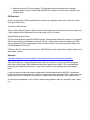
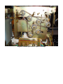
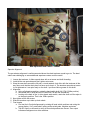
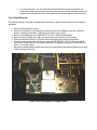
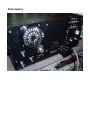
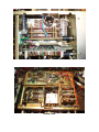
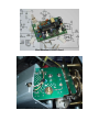
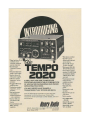
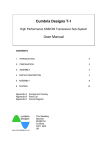
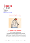
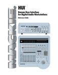
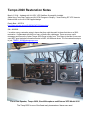
Tempo 2020 Restoration Notes March 2, 2014 – Updated with X-LOCK, VFO Stabilizer Successfully Installed Added Long Term Heat Testing and X-LOCK Changes to Simplify – Uses Existing RIT VFO Varactor Network Now vs. the X-LOCK supplied design. Randy Best – W7CPA http://www.arizona-am.net/PHOENIX/W7CPA/index.html SN = 6060025 I’ve written up my restoration notes in hopes that they might be useful to those that take on a 2020 restoration. I collaborated with N4PL on many of these tasty challenges. There are many useful messages and files on the Yahoo Tempo 2020 Group to learn from. This Group is the best I have ever seen WRT good technical information thanks to N4PL, KX4OM and others. The first restoration step is to join: [email protected] Front View Speaker, Tempo 2020, Stock Microphone and External VFO Model 8010 The Temp 2020 is one of the finest early transceivers I have ever used. Front View I would then download the user and alignment manuals and all the N4PL files plus the 3 flavors of sprocket repair. The annotated schematics are excellent. Use these in combination with the User Manual module schematics. After all this fun, I strongly suggest not attempting to work on this rig unless you have RF circuit lab tech experience and a pretty robust set of lab equipment with a calibrated VTVM like and HP-410C and a quality frequency counter. Replacement parts are all pretty “unobtanium” except for NTE replacement matches, caps and resistors. Buying a parts rig is also highly recommended. Suggested First Steps 1. Power up for 48 hours with a variac or 100 watt light bulb in series with the AC mains to re-from old electrolytic capacitors. I have not had to replace any high or low voltage capacitors after this, fingers crossed. 2. Verify/adjust all AVR board voltages. I adjusted 8.2VDC and 5VDC no problem but my 6VDC output for was a low 5.3VDC (should be 5.5-6.5VDC and is used solely for VFO. After considerable research, I discovered that the 2SC372Y transistors are very poor fab/materials and the 6 volt regulation was horrible resulting in a 50Hz transmit-receive delta. I replaced Q658 with an NTE85 and I now have 6.2VDC with very good regulation. I subsequently changed all other 2SC372Ys on the AVR board hoping to improve 8.2VDC regulation. This second effort yielded marginally better improvements. 3. Measure driver and PA tube voltages. The Alignment Manual has tables with the proper voltages. Make sure the 6146B screen grid 200 VDC regulation has not been molested or has an open zener. CB Exorcism One of my brand new 6146W experienced an internal short (explosion white splat on the side, blown fuse, open filament etc). Transmit on CB Channels This involves adding a jumper on the Driver board band switch and tweaking the Driver tube output coil. I left the jumper and re-adjusted the Driver tube output coil for 10 meters. Stupid Attempt at More Power The PA screen grid has a regulated 200VDC design. Someone had removed the series 5.1k 2 watt and 200 volt zener to ground and added a series 7k resistor. I believe this resulted in blowing my 6146W since I measured 356 volt swings down to 290 volts when loaded. The max screen grid voltage in the 6146W datasheet is 250 volts! NTE has a 200 volt 10 watt stud mount zener (NTE5232A) that works well. Earlier models used two five watt zeners in series. Sprocket http://www.dailymotion.com/video/x9p5ey_sprockets-germany-s-most-disturbing_shortfilms After initial inspection, I was gloating that there were zero cracks on my nylon sprockets and gears – what a buy, what a buyer. Much had been written about geezer nylon cracks. This soon faded after performing the calibration procedures – many cracks now plus some slippage even after adding C rings. I used the excellent chain and sprocket replacement instructions provided by KX4OM. I recommend biting the bullet and replace them all. I tried the C rings first but they eventually failed – simply too much geezer nylon dying. It would also be possible to use ball chains and sprockets vs. the ladder chains. A crack had also appeared on one of the LO board tuning capacitor gears so I replaced it from a parts rig. Original Cracked Nylon with C-clips Fix Attempt New Sprockets and Chains – Whew! Sprocket Alignment The pre-selector alignment is well documented where the chain tensioner needs to go etc. The band switch was challenging so some additional experience notes could be useful. 1. Loosen the tensioner, it slides up and down with a set screw and shaft threading. 2. Install all the new sprockets and don’t tighten set screws. 3. Wrap the new chain around the full path, cut and reattach chain links with the tensioner all the way down such that the chain does not have much slop in it. The tensioner sprocket set screw is not tightened so it can spin freely on the shaft. I put some lithium grease on this shaft. 4. Alignment a. Using a flathead screwdriver, rotate the band switch shaft full CCW (15Mhz position). b. Now rotate the LO shaft and the RF board full CW with the screwdriver. c. Looking at the back of the 1st driver board wafer switch, rotate the shaft until the wiper is on the empty position. That is the 15Mhz position. 5. Now tighten all the set screws. 6. Slide the tensioner up to take up chain shack. 7. Final tweaks a. First test the LO switch alignments by rotating all band switch positions and noting the proper display. If off, rotate shaft, looking at the switch pads, retighten and retest. b. Test RF output on all bands to verify driver switch positions are correct. Zero output indicates misalignment on driver switches. c. If you are really anal, you can now rotate the band switch through all positions and inspect the switch contact positions for somewhere close to being centered. Loosen the sprocket set screws and do minor shaft rotations with needle nose for quasi perfection. Front Panel Removal Front panel removal is required to change lamp inside drum, replace toggle switches and fix/replace sprockets. 1. Remove top and bottom covers. 2. Remove front bezel by unscrewing all stainless counter sunk Phillips screws top, sides and bottom. Carefully pull forward. This was a very tight fit on my 2020. 3. Remove the following knobs: PRESELECT, PLATE, LOAD and BAND MHz. 4. Remove the top Phillips to the right of center that secures the front to the chassis 5. Remove the bottom Phillips to the left of center that secures the front to the chassis. 6. Carefully rotate the front panel forward to clear the PRESELECT, PLATE, LOAD and BAND MHz shafts. It has hinges on the bottom that allow a 90 degree tilt forward over the edge of a desk – a very nice design. 7. Be careful rotating the front panel down since the mode switch has exposed diodes on the back. I had one break off the lug. Front Panel Unfastened and Hinged Down Low MIC Gain The stock Tempo high output hand mic required the mic gain almost fully clockwise and some bands would never indicate ALC action. I understand the original design was a bit conservative, low noise, high linearity and all that. Since I couldn’t even use my D-104, I had to make changes, stone the crows. The mic amp is on PC-080 - an OP AMP + gain pot + NPN transistor. I download the PC-080 Toshiba Q505 TA7063P datasheet. The OP AMP datasheet shows a test circuit using a 22k feedback resistor for a 45DB gain. The 2020 has a 6.8k (R551) feedback resistor – the conservative bit. The fix/mod is easy. Unplug PC-080 card, replace R551 with a 15k resistor and batta bing, batta boom, mic gain now at 12 o’clock drive ALC to a mid point indication with stock mic and many others. The waveforms still look nice, no obvious distortion by increasing the OP AMP gain a wee bit. Since have I no reference data, I can’t classify MOD or FIX at this time. Mind you, an old electrolytic might also be in play. All I know is my 2020 is perfect now. Low Power Output Problem 1 I followed the Driver board calibration instructions and found that I no longer had 15 or 10 meter output. The problem was the alignment instructions are flat wrong. The DRIVER card input coil L251 should be peaked on 15 meters, not on 75 as shown in the table. It is so broad on 75 that you can easily set it at a point where no 15 or 10 gazouta happens. Problem 2 I found that power output would drop off from 100 watts to 88 on 14 Mhz after warm up. Replacing the driver tube made no difference. I purchased 2 new, matched GE 6146W tubes from RF Parts and all is well now. Problem 3 Some bands have only 60 watts max out. New Driver and final tubes made no difference. The problem was determined to be the band switch sprocket slippage combined with an intermittent relay contact for PA bias switching. See the sprocket change section above and remove the plug-in relay and properly clean and burnish the contacts. I was testing on the bench only in the Tune position so I wasn’t seeing the PA bias intermittent behavior. Problem 4 After sprocket and chain replacement, 80, 40 and 20 had fine outputs of 100 watts on all SEGMENTS. 15 and 10 still stuck at 50-60. The problem was the band pass filters, see below. LO Oscillator Adjustment I followed the alignment instructions precisely using TP-2. You will chase red herrings unless you use a high quality RF VTVM to set all outputs to 1.5VRMS first then couple the counter/scope-counter to TP-2 through a 1-2pf cap to set the required frequencies for each band. If you don’t use the small coupling cap, the frequency will read low on your counter. LO Card Band Pass Filter Adjustment My bad past experience tells me never mess with band pass filters to avoid damaging unobtanium coils etc. Since I was having output problems on 15 and 10, I ventured on. The alignment manual references a desired waveform figure but this does not exist. I tried both of the following with good results: 1. Manual described alignment procedures - I also played with my HP sweep generator and spectrum analyzer as well to achieve a nice flat response. Sweep 15.338 MHz to 15.838 MHz (from N4PLs most excellent “Tempo 2020 Mixing and Display” spreadsheet. The spectrum analyzer made it much easier to perform the final tweaks for flatness at the ends. 2. Easy street REVISED – I discovered that my spectrum analyzer probe must have loaded down the LO output in 15 and 10. The new procedure is to monitor the level on the TRANSVERTER OUT RCA jack with the PA slide SW off with a scope or RF voltmeter. Place dial midpoint at 50 KHz. Sequence though all the SEGMENT buttons, peaking PRESELECT each time and adjust the 2 coils for each band for as close to possible to the same output levels on all SEGMENTS. This is just as satisfactory as 1. above and much, much simpler. The LO out is high impedance and easily loaded down. The driver output is well isolated and results in optimum tweakage on 15 and 10 – I now have >100 watts on 15 and 10, all SEGMENTS. VFO No changes were required in my external VFO, end points were right on and no changes were made other than case cleanup. It had a CB WARNING sticker that left what looked like permanent paint damage. I used many applications of soap and water to fix. DO NOT USE alcohol or any chemicals on elderly paint, ever. I learned this the hard way on other griefkit projects. I had to reset the internal VFO endpoints after fixing the 6 VDC regulation problems on the AVR card since VFO 5.3 VDC is now where it should be at 6.0 VDC. I suggest warming up for an hour before adjusting so your dial indicator will be centered when warmed up. The addition of a NTE962 (below) to regulate the 6VDC VFO supply substantially reduced the long term negative drift after 30 minutes. It was within specification but it’s mo better now. Does Not Transmit and Receive on the Same Frequency I measured a 50Hz annoying delta. The first problem was that the 6VDC VFO regulated supply wasn’t. I was seeing 5.380VDC on receive and 5.430VDC on transmit – not well regulated for sure. Even after the Q658 change to NTE85, both 6 volt and 8.2 are not perfectly regulated and still have a small XMT/REC delta of 20Hz. Adventuring further into the abyss, I added a 3 legged modern regulator NTE962 for a more precision 6VDC VFO voltage. Cut the trace near PIN 5 (6 VDC output) on the AVR board. Double side tape the NTE962 to the bottom of the AVR. Solder NTE962 output to PIN 5. Connect NTE962 center pin to the ground plane. Solder the NET962 input to PIN 2 (12VDC). I still see a 20Hz delta and less long term drift so this is not worth the effort. I recommend just replacing Q658 (above) for the best bang for the buck if your AVR VFO 6VDC is less than 5.5 volts (spec is 5.5-6.5) replace Q658. Now on to Valhalla – 0Hz delta. It turns out diodes D751-D754 on the Operations Board (085) had substantial forward voltage drop differences. I replaced them with 4 matched HP diodes and perfection is achieved. You have to remove the Operations Board (front panel drop) to replace them given they are hidden under the rotary switch. See the photo below of the board removed where the diodes live under the switch. The parts list does not note matched, but they sure need to be reasonably matched if you want to transmit and receive on the same frequency. Maybe the junction deteriorated over time. I suggest using 1N914/1N4148 diodes matched with a Fluke. My balanced modulator HP diodes work but are really too frail for this duty. PA Neutralization Connect a dummy load and place rig on its side or face down. Set to 15 meters, load up. Now adjust the neutralization capacitor, only accessible on the PA bottom area with an insulated screwdriver for max RF output at the PA current dip point. Be careful not to key down very long each time. If you don’t use an insulated screwdriver, you deserve to be thrown across the room. Lamp Replacement I didn’t have to replace any bulbs. This is a good thing because my fingers could never reach into the dial drums to twist the bulb. This looks like more disassembly is required and a rear challenge. I know one thing for sure; make sure you replace with #1826, 16 or 18V Volt 0.15 Amp bulbs only. Using 12 volt high current bulbs generate too much heat and will damage the unobtanium drum. The little wheat bulbs in the meter are easy since they are pushed in through rubber grommets from the back. Once again, use only the right bulb - 12 volt 50 ma. DD-103 Digital Display I hooked up a DD-103 digital display to the LO XMT output (J103). This way it displays actual frequency by using a minus 6.187 MHz offset programming in the DD-103 unit. The DD-103 powered, one transistor interface is required. I soldered to the backside (possible without board removal if you are careful) on the LO board to J103 pin 1. This sample point makes it easy in the DD-103. All that’s required is to subtract the IF frequency. I used one of the phone patch RCA jacks to get the signal out of the box. I never run phone patches so no loss. X-LOCK VFO Stabilizer Since I decided the rig was definitely a keeper, I installed X-LOCK in my external VFO. If you follow the directions below, a nice side effect is the first character distortion on CW gets fixed since the VFO voltage no longer blinks off/on during T/R transitions. The finest stabilizer available today is the X-LOCK kit. The X-Lock locks a VFO to a crystal source to provide drift free operation. This design takes a fresh approach to the "Huff-Puff" Frequency Locked Loop technique by using a processor to measure frequency and compute correction signals. The XLock employs a 100mSec count period to produce 10Hz "lock points" against which the host VFO will be held. Dual regulators are used to supply the digital and analogue sections of the circuit which in turn are optically coupled to produce an exceptionally clean control voltage. The X-Lock will accept input signals from a few kHz up to 50MHz to provide up over 6 volts of control range. Features include auto lock/unlock during tuning, RIT detection and fast re-lock, power on reset auto centering, and a dual colored LED to indicate lock and input states. Your VFO must have a reasonably good sine wave and not drift more than 40 Hz / second before XLOCK can do its magic. The Tempo 2020 meets these requirements quite well. Website and manual download: http://www.cumbriadesigns.co.uk/x-lock.htm See installation detail pictures in the gallery below. The Model 810 external VFO is relatively easy to add the X-LOCK. You could also do the internal VFO with more mechanical complexity. Only the external VFO is presented here. I experimented with using the standard X-LOCK varactor control network connected to the VFO tuning capacitor. I had to abandon this because of instability after resetting the dial end points – variable L too far away from original design. It turns out the VFO already has a varactor control network used for RIT with a 6VDC supply. I tried using this instead with excellent results. The X-LOCK control voltage range is 0-6VDC. Simply coupling the X-LOCK DC control voltage though a 10k resistor to VFO connector Pin#1 (now in parallel with the RIT DC VFO input) seemed to play well at not affect the dial end point settings. From cold to warm (2 hour bench test) the X-LOCK control voltage ranged from 3.795 VDC to 4.175 VDC to maintain zero VFO drift – EUREKA. 1. Build the X-LOCK kit. It is easy to test on the bench if you have a signal generator and 12 volt supply. 2. Remove the external VFO top and bottom covers. 3. First, fix the T/R transition VFO voltage dropout problem by adding a 470uf, 25 volt electrolytic between the VFO DC input and ground. This problem blocked a previous X-LOCK attempt since it starts over every T/R transition due to goofy the 2020 switching. I apparently did not try enough capacitance on my first X-LOCK attempt. I connected the cap to the bottom left VFO/SPLIT SW terminal (looking from the back) and the ground lug on the VFO cover. 4. Remove the VFO can covers, easy, 4 screws. 5. Thread the DC control and RF sample wires through the adjustment holes. I grounded the coax cable only at the X-LOCK connector to avoid a weird ground loop problem that had me scratching my head why it wouldn’t lock with a perfect RF waveform. 6. Connect the RF sample coax to the PC board bottom where the short little coax connects to the VFO jack on the back (see gallery pictures below). According to Cumbria, the RF IN signal can range for 500mv to 30v pk-pk. The Tempo 2020 buffer outputs 1.9 v pk-pk – well within the range, no need for a pad to reduce this level. 7. Connect the X-LOCK 12VDC input to the front panel SW with the fat red wire. I connected ground to a lug on the VFO cover. 8. Connect X-LOCK DC control voltage through a 1N4007 diode (bypass X-LOCK side with a 10pf) then a 3.3K resistor to the pad where the current 10k RIT voltage resistor connects - a summing junction of sorts. Use an ohm meter to find it from PIN 1 <-> 220uh choke <-> 10k <-> X-LOCK 3.3K. I used a twisted pair and grounded nearby the resistor install. The diode is required to block the RIT voltage from getting back into the X-LOCK and getting its panties in a bunch. 10K did not provided enough control voltage so 3.3K was arrived at by trial and error. 9. Program the post tuning delay to 4 seconds to give you time to tune on the beak before if locks down. The default 2 seconds gets annoying when tuning with the DD-103, 10 Hz resolution display. 10. I mounted the X-LOCK on a plastic box to avoid a weird problem I had if the X-LOCK pc board got too close to the metal case area. 11. You will have to adjust the 3 RIT pots to center the knobs due to the now shared use of the RIT varactor network. This is kind of tricky. R215 is the CENTER pot. R214 is the WIDE center POT. R213 is the NARROW center pot. If you can’t set R214/R213 then move R215 and try again until you can turn RIT on and the WIDE and CENTER knobs are close when the dial shows centered. 12. The X-LOCK can manage 2 set points so this enables receiver RIT operations very well and does not walk down the band on transmit – a brilliant design. 13. Since the radio frequency = VFO + LO OSC, there will still be a small drift until the LO OSC stabilizes but after that, stability rules. Conclusions The oddball hybrid frequency display is amazingly accurate and linear, end to end, on each segment – better than all my vacuum tube Collins gear. Also, one can QSO instantly to CW segment without have to crank the dial forever. The receiver audio is amazingly clean and smooth and fun to listen to. Now my KWM2-A and the Temp0 2020 are my top shelf listening smoothies. The transmit audio gets excellent reports with the stock Tempo mic and ever better with a D104. AM operation is exceptional if you lower the carrier to 10-20 watts and drive an amplifier. I am seeing 100% modulation and HiFi 16kHz bandwidth. You have to use RIT on receive since the USB SSB filter is used on receive vs. a proper AM filter. I am looking into using both SSB filers on receive but this might not be possible impedance wise and too messy of a MOD. This is an extremely well done design and a keeper for sure. My Collins HF-380 had some mechanical design flaws they could have learned from with this old puppy. I am seeing around -350 Hz drift in the initial 30 minutes. It then stabilizes but never totally stops, just slows way down. The external VFO drifts -310Hz in the first 30 minutes then stabilizes with substantially less long term drift than the internal VFO as one would expect. The factory specification calls for up to 100Hz per hour after warm up so this is not too stellar to start with but – it is a geezer after all and the application of the X-LOCK unit stops all drifting cold so definitely worth the effort. The SSB carrier null is the best I have ever seen, >70DB, possibly due to the dual SSB filters with no compromised required on null settings. The separate LSB and USB filters enable absolutely the same audio response on LSB and USB. The PA cage blower keeps the internal chassis temps nice and cool. It’s relatively quiet, not bad. The noise blanker is one of the best I have ever used. Photo Gallery Back Panel Driver Board with DD-103 Interface View Bottom View Top View Unique Hybrid Display PA Bottom, Note Proper Stud Mounted 200 Volt Zener Diode Operations Board (085) Removed for T/R Delta Diode Fix Most Excellent X-LOCK Board VFO Can Removed, 10k Resistor and 2 Connections VFO Can Back On and X-LOCK Board Mounted to the Side with Velco