1
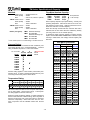
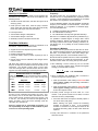
TM Series, Specifications & Capacity Materials: Flow Meter Nominal Capacity: TM●●A Case & cover : Anodized aluminum Posts (shafts) : 316SS Seal : Viton™ std., Teflon™ optional TM02D TM03 TM04 TM06 TM●●C Case & cover* : 303SS Posts (shafts) : 316SS Seal : Teflon™ standard TM04 TM06 SS/Teflon bearings PPS standard, SS/Teflon bearings opt. To determine model maximum capacity on higher viscosity liquids, find the flow meter coefficient for maximum liquid viscosity in table below, and multiply nominal capacity with this factor. PPS standard PPS standard Pressure Rating: TM Series meters are manufactured with 2 different pressure ratings (though not in all sizes/materials). Pressure rating is identified in position 11 in the Part Number: MODEL TM02D TM03A TM03D TM04A TM04C TM04D TM06A TM06C TM06D K L 1500 PSI 103 BAR 2500 PSI 173 BAR F obsolete 2009 400 PSI 28 BAR Pressure rating applies to -40ºF/+100ºF (-40ºC/+38ºC) temperature range. At higher operating temperatures the pressure rating is reduced by factors shown below: Temperature Rating: -40°F/+100°F 150°F 200°F 225°F 250°F 275°F 300°F -40°C/+100°C 66°C A.A. S.S. On liquids with 1 cSt viscosity. When the viscosity exceeds 200 cSt, maximum flow rate is restricted, but the flow meter will have satisfactory linearity (accuracy) down to 2-3% of nominal capacity. * Pulser retainer (exterior non-wetted fitting) is anodized aluminum. Pos. 11 in P/No. 1.1 lpm 11 lpm 38 lpm 76 lpm Actual capacity depends upon liquid lubricity, viscosity and operating temperature. Normal turn-down is 10:1 from nominal (maximum) value shown. Optimum performance is between 50% and 85% of nominal capacity. TM●●D Case & cover* : 316SS Posts (shafts) : 316SS Seal : Teflon™ standard Rotors (oval gears) : TM02 TM03 0.3 GPM 3.0 GPM 10 GPM 20 GPM 93°C 107°C 121°C 135°C 150°C 1.00 0.89 0.79 0.75 0.72 0.62 0.43 1.00 0.91 0.83 0.79 0.74 0.70 0.67 TM Series meters are rated for use on liquids with temperature in -40ºF/+300ºF (-40ºC/+150ºC) range. This temperature rating applies to the flow meter only. Electronic signal conditioner, totalizer or register attached to the flow meter will have a different rating, which may differ at both the low and high end of the range (refer to manual for electronic components). When that is the case, the electronic component must be installed remote from the flow meter. 1.4 Flow Meter Coefficient Liquid Liquid Rotor Code Viscosity A E & K Viscosity 1 cSt 10 50 100 200 300 400 500 600 700 800 900 1,000 2,000 3,000 4,000 5,000 6,000 7,000 8,000 9,000 10,000 20,000 30,000 40,000 50,000 60,000 70,000 80,000 90,000 100,000 1.000 1.000 1.000 1.000 1.000 0.855 0.770 0.710 0.660 0.625 0.595 0.560 0.540 0.350 0.275 0.240 0.190 0.160 0.135 0.115 0.100 1.000 1.000 1.000 1.000 1.000 0.855 0.770 0.710 0.660 0.625 0.595 0.560 0.540 0.350 0.275 0.240 0.190 0.160 0.135 0.115 0.100 0.085 0.072 0.061 0.052 0.044 0.037 0.031 0.026 0.022 0.019 32 SSU 60 240 475 925 1,425 1,875 2,350 2,825 3,300 3,775 4,250 4,725 9,450 14,150 18,875 23,600 28,325 33,050 37,750 42,475 47,200 94,400 141,600 188,800 236,000 283,200 330,400 377,600 424,800 472,000