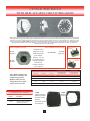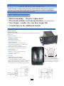
1
Pollak®
A Stoneridge Company
worldwide
engineered
solutions
to design
challenges
Catalog MC-612
Pollak®
A Stoneridge Company
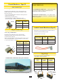
Since 1909, Pollak® has provided the transportation
industry with innovative designs, reliable manufacturing,
high quality standards, competitive pricing and
low life cycle costs. More than 1000 employees
located in three manufacturing locations totaling
approximately 250,000 square feet of design, test and
production space are now providing custom and standard
components to OEM’s and aftermarket suppliers in
automotive, light, medium and heavy duty truck,
agricultural, construction equipment, marine and
related industries. Pollak® excels in its ability to
design and manufacture from the concept stage
through manual, semi-automatic and fully
automated, high volume production. Pollak® is a
certified ISO9001/QS9000 manufacturer and has
also earned Q1 preferred status at Ford, General
Motors’ Mark of Excellence, Chrysler’s Gold Pentastar,
Navistar V and similar rankings with PACCAR,
Freightliner, John Deere, Case, Caterpillar,
Borg-Warner and other respected OEM’s.
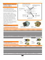
Pollak’s Control Devices Division located in Canton, MA is a leading
supplier of electrical connectors, switches, and sensors. This division
develops, manufactures and supplies a
wide variety of electromechanical products
including toggle,
rocker, door, pedal
and ignition switches,
back-up alarms, circuit
breakers and related
items.
Control Devices Division
300 Dan Road, Canton, MA 02021
Tel. 781-830-0340 ◆ Fax: 781-830-9570
Pollak’s Electronics Division located in El Paso, TX and Juarez, Mexico
is the largest independent producer of electronic displays for the North
American Trucking
industry.This division
designs and manufactures electronic
modules, power
converters and
instrument clusters
for transportation
related industries.
Electronic Products Division
11801 Miriam Drive, Suite B1, El Paso, TX 79936
Tel: 915-592-5700 ◆ Fax: 915-593-7379
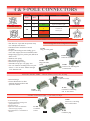
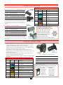
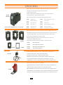
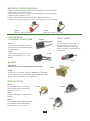
ELECTRICAL CONTROLS
CONNECTORS/
ADAPTERS
For senior design engineers at major OEM’s, the operator of a heavy duty
truck or the weekend camper, the name Pollak® has always symbolized
technology and quality.
As a Stoneridge Company, Pollak continues the tradition today.
SWITCHES
CIRCUIT
BREAKERS
SPECIALIZED
ELECTRICAL
PRODUCTS
FUEL TANK
SELECTOR
VALVES
BACK-UP
ALARMS
Our Global Network
SPD – Canton, MA
EPD – El Paso/Juarez
Alphabet – Warren, OH
Hi-Stat – Lexington, OH
DAV – France
Positron – Brazil
Berifors – Sweden
Connecto AB – Poland
North American Sales Offices –
◆ Novi, MI
Sales & Engineering Offices –
◆ Frankfurt, Stuttgart, Munich – Germany
◆ London, Mitcheldean, UK (Sales Office)
◆ Säo Paulo, Brazil
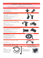
3
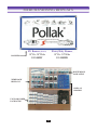
MERCHANDISING
DISPLAYS
Stoneridge
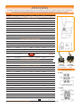
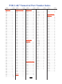
ALPHABETICAL INDEX
(See Numerical Index, pages 66-67)
Adapters
Adaptor Housing, Connector
Alarms, Back-up
Anti-Restart Ignition Switches
Axle Switches
Back-up Alarms and Switches
Back-up Lamp Switches (Ball Operated)
Battery Disconnect Switches
Battery Jumper Terminals
Boot Nut, Starter Switch
Brackets, Connector
Buzzer
Circuit Breakers
Circuit Breakers Brackets
Circuit Breakers Sockets
Circuit Breakers Junction Box
Connector Hardware Kits
Connectors, Molded
Connectors, Trailer
Dimmer Switches
Displays (Merchandising)
Door Switches
Electronic Dimmer Switches
Fuel Tank Selector Valves
Fuse Blocks
Fuse Holders
Fuse Panels
Harness, Trailer Wiring
Horn Buttons
14,16-17
9
55-58
29-33
24,39
55-58
27-28
35-36
12, 49
26
8,10,12,14,15
49
40-46
45
9
48
7,10
13
5-13
38
59-64
39
37
51-54
48
48
48
14,16
49
Ignition Starter & Lock Switches
Ignition Starter & Lock Switches (Marine)
Inserts, Plugs
Inserts, Sockets
Master Disconnect Switches
Merchandisers
Molded Connectors
Momentary Start Switches
Momentary Start Switches (Marine)
Panel Indicator Light (Pilot Light)
Plug Interiors, Connector
Plunger Switches
Push/Pull Switches (Marine)
Push/Pull Switches
Rocker Switches
Rocker Switches Accessories
RV Connectors
Sealed Beam Connectors
Starter Solenoid Switches
Stop Light Switches
Terminal Blocks
Toggle Accessories
Toggle Switches
Trailer Connectors
Transmission Mounted Switches
Universal Connector Brackets
Valves, Electrical Fuel Tank Selector
Value Line Connectors and Adapters
Wiring Color Codes
29-34
33
6
7-8
35,36
59-64
13
25,26
26
49
6
26,39
24
24
21,22
22
10-15
49
38
39
48
21,22
19-22
6-15
27,28
8,10,14,15
52-54
64
65
WARRANTY
Our products are warranted to be free of manufacturing defects for one (1) year after date of manufacture. Buyer’s
exclusive remedy and seller’s sole liability hereunder shall be limited to refund of the purchase price or replacement of
product shown to be other than as warranted. Conditions resulting from misuse, negligence, accident or improper
installation, maintenance or application shall absolve seller of all liability. The foregoing constitutes the sole warranty of
Pollak® with respect to its products and is in lieu of all other warranties, expressed or implied, including any implied
warranty of merchantability or fitness for a particular purpose. In no event shall Pollak® be liable of consequential or
special damages.
The product information published in this catalog is subject to change without notice. Changes to materials,
finishes, technical specifications and other product characteristics may be necessary at our discretion. It is the
buyer's responsibility to determine the suitability of the Pollak® device for its application. Pollak® makes no
warranties, and assumes no liability as to the suitability or sufficiency for buyer's application of the device.
4
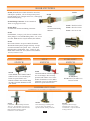
CONNECTORS & ADAPTERS
5
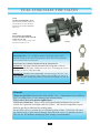
7-POLE PLUGS
SOLID BRASS
PINS
HOUSING
AVAILABLE IN ZINC
DIE-CAST OR GLASS
FILLED NYLON
INTEGRAL LEAF
SPRING
MOISTURE RESISTANT
WEATHER-BEATER SEAL
CONVENIENT
HANG RING
PROTECTIVE GREASE
ADDED
SOLID HIGH IMPACT
CYCOLAC CONTACT
RETAINER
CABLE LOCK
PLATED STEEL
RETAINER SCREW
ZINC
DIE-CAST
11-902
Weather-Beater
Plug with Cable
Guard
11-702
Standard 7-Pole
Plug with Cable
Guard
HIGH STRENGTH CLOSE COILED ZINC
PLATED SPRING STEEL CABLE GUARD
GLASS
FILLED NYLON
11-910
WeatherBeater Plug
with Cable
Guard
11-710
Standard 7-Pole
Plug with Cable
Guard
11-900
WeatherBeater Plug
11-700
Standard 7Pole Plug
11-704
Standard
7-Pole Plug
11-904
Weather-Beater
Plug
Insertion and Pull-Out
Requirements
Meets and exceeds all standards of SAE J560.
Floating pins for ease of alignment and
maximum contact.
Will accept the widest range of wire gauges,
from #16 wires to #8 ground wire.
Tapered design fits comfortably and
conveniently for easy hand-position pull.
Jumbo finger pull grips and two hang-up
holes.
High-impact cycolac interior with extended lip
for easy removal and replacement.
Solid brass terminal screws.
40 amps continuous duty @ 6-28 VDC.
WeatherBeater seal accommodates .450
minimum wire diameter.
NOTE: Pollak’s® Terminal Pins are machined from
solid brass bar stock unlike some competitors that
provide unplated terminal pins stamped from sheet
metal. Brass terminals ensure minimum voltage drop
and dielectric grease protects against corrosion and
resistance.
NOTE: Pollak’s ® 7-Pole connectors are
manufactured from quality materials and will help
reduce maintenance cost and down-time associated
with electrical failures.
ACCESSORIES
11-762
Rubber Boot
Seals against dust and
moisture, 2.5" long. For
.460-.720 dia. cable, fits 11852, 11-700, 11-900,11-704,
11-904.
11-763
Cable Guard
Plated steel, 3.56"
long, fits 11-700,
11-704, 11-900,
11-904, and
11-852
11-764
Plug interior for
11-700,11-702,11-704,
11-710,11-900,11-902,
11-904,11-910.
Supplied with mounting
screw.
6
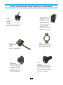
7-POLE SOCKETS
Meets and exceeds all standards of
SAEJ560 (SAE applies only to solid pins)
Floating pins for ease of alignment and
maximum contact.
Optimum slant mount and drain slot rid
housing interior of accumulated moisture.
Will accept the widest range of gauges
from #16 wires to #8 ground wire. Ground
Terminal Pin #1 will accept #14 gauge
min. to #8 gauge max. Other terminals will
accept #16 gauge min. to #10 gauge max.
40 Amps continuous duty @ 6-28 VDC.
Self grounded. (Zinc Die-Cast Units Only)
to #1 Ground Terminal.
Stainless steel spring.
Recommended Mounting Hole is 2"
diameter
Interchangeable with competitive makes.
No.
Color
Wire
Gauge
FMVSS121 AntiLock
Gauge
1
White
10
8
Ground Return
2
Black
12
12
Clearance, Side Marker and Identification
Lamps
3
Yellow
12
12
Left Turn & Hazard Signal
4
Red
12
10
Stop Lamps & Anti-Lock Devices
5
Green
12
12
Right Turn Signal & Hazard Signal
6
Brown
12
12
Tail, Rear Clearance Marker, License
Plate Lamp
7
Blue
12
12
Auxiliary Circuit / ABS Power
Circuit
WIRE INSERTION STYLE SOCKETS
DRAIN SLOT IN COVER
ZINC
DIE-CAST
11-729
Solid Pin
3 hole mount
11-720
Solid Pin
2 hole mount
11-730
Split Pin
3 hole mount
11-721
Split Pin
2 hole mount
POLLA/GLASS
GLASS FILLED
NYLON
BOTTOM LIP EXTENDED
FOR BETTER PLUG
SUPPORT
11-723
Nylon socket
Solid Pin
11-724
Nylon socket
Split Pin
BUILT-IN OPTIMUM SLANT
FOR DRAINAGE
ACCESSORIES
11-761
7 Pole Socket
Rubber Socket Boot
for 11-720,11-721, 11723, 11-724, 11729,11-730 and 11852; seals against dust
and moisture, 1.5"
long. For .460-.720
diameter cable.
11-780
Neoprene rubber
gasket for 3 hole
mount die-cast sockets.
May be used as
template
11-773
Same as 11-780
except for 2 hole
mount sockets.
11-771
7-Pole Socket bracket.
Fits all 7-Pole Sockets
including 11-851.
7
11-777
Hardware Kit
for 7-Pole Plugs
(except RV)
11-781
Hardware Kit
for 7-Pole Zinc
Die-Cast Socket
11-779
Hardware Kit for
7-Pole Molded
Polla/Glass Sockets
7-POLE SOCKETS
ZINC DIE-CAST
BODY & COVER
DURABLE
THERMOSET PLASTIC
BASE
VIEW – REAR OF SOCKET
SLOTTED
GALVANIZED STEEL
SET SCREWS
ENCLOSED
STAINLESS STEEL
SPRING
DRAIN SLOT IN
COVER
EXTENDED LIP FOR
PLUG SUPPORT
SOLID BRASS
PINS
NEOPRENE RUBBER
WEATHER
RESISTANT BOOT
RING TERMINATION
STYLE SOCKETS
BULLET TERMINATION
STYLE SOCKETS
11-785
Same as 11-720
except with rear
threaded
terminals for
ring terminals.
Solid Pins.
11-786
Bullet-Style solid brass
terminals for push-on
terminals. Will accept
straight or "right angle"
terminals. Extended hinge
pin and external spring for
increased closure force.
11-797
Same as 11-786 except
without extended hinge
pin and external spring.
Solid Pins
Note: For some applications
ring terminals provide a better
mechanical connection than
set screws when properly
installed.
11-833 (Not Shown)
Same as 11-797 except
with glass filled nylon
shell and lid
ISO TYPE CONNECTORS
12-812
ISO 7-Way
Connector Socket
12-811
ISO 7-Way Plug with
cable guard
8
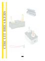
7-POLE SOCKETS
WITH REPLACEABLE CIRCUIT BREAKERS
Base plate and back plate made from rugged glass filled nylon to resist breaking. Bottom lip has been extended to
allow for better plug and cable support. Drain hole has been incorporated into the housing to allow accumulated
moisture to escape. Will accept the widest range of wire gauges from #14 wire to #8 ground wire. Will accept all
plugs conforming to SAE J560 specifications. Ground may be tied to any screw mounting the rear terminal plate.
Designed to provide easy serviceability of circuit breakers. Recommended that positive feed be attached to
auxiliary post on circuit breaker.
WIRE INSERTION STYLE
Standard socket
adapted to circuit
breaker mounting
plate without
breakers. For use
as a replacement of
original equipment
when circuit
breaker protection
is not required.
11-732
Solid Pin
11-733
Split Pin
Glass filled nylon nose box
offers more durability and
weight saving features.
Replaces old style heavy
weight metal boxes which
can cause short circuits.
COMPONENT PARTS
Part No.
RING TERMINATION STYLE
Description
11-801
Adapter Housing Gasket
11-802
Adapter Housing (Includes
Grommet and Screws)
(Not shown)
Metal Circuit
Breaker
11 -796
Sp lit Pin
Plastic Circuit
Breaker
Replacement
Circuit Breaker
Plastic Housing
Amperage
Pin Type
Part No.
Replacement
Circuit Breaker
Metal Housing
15
Split
11-735
54-115
*
20
Solid
11-736
54-120
54-120PL
20
Split
11-737
54-120
54-120PL
30
Split
11-739
54-130
54-130PL
11-801
Adapter Housing
Mounting Gasket
provides weather
resistant
protection against
rain and snow.
9
11-802
Adapter
Housing
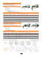
6-POLE CONNECTORS
6-POLE
SOCKET
Number
Color
Circuits
GD
White
Ground Return
TM
Brown
Tail Lights
LT
Yellow
Left Turn
S
Red
Stop and/or Electric Brake
RT
Green
Right Turn
A
Blue
Auxiliary Circuit (Center)
(Auxiliary in center)
Complete Assemblies (Plug and Socket)
Part No
Plug
Socket
11-600
11-604
11-607
11-602
11-604
11-608
11-603
11-604
11-609
11-603 Assembly incorporates concealed
terminals on socket side for exterior
mounting. Recommended for RV and flat
bed trailer use.
11-604
Plug, no
cableguard
11-607
Socket, exposed
terminals
11-605
Plug with
cableguard
11-614
Black Plastic
Socket with
metal lid
11-608
Socket with
rubber boot
11-609
Socket,
Concealed
Terminals
6-POLE
PLUG
(Auxiliary in center)
Three socket versions to choose
from: Exposed terminals, Rubber
boot coverage, or Die-Cast shell
coverage. High impact plug
interiors keyed for proper
assembly. Machined brass
terminal pins for best conductivity,
terminals accept up to #12 gauge
wires. Plug available with or
without cable guard. Replaceable
plug interior helps reduce
maintenance costs. Plated steel
cable guard prevents cable
chafing. Two 1/4” diameter
mounting holes on 6-Pole sockets.
2-7/8” diameter on center. Mounts
through 1-3/8” diameter hole.
Note: Pollak’s ® 4-pole and 6-pole interiors
are secured with a key and keyway to
eliminate twisting (disorientation) and
breakage with make and break forces that
apply in normal function.
12-720
6-Pole all Plastic
Socket with
rubber boot
11-613
Connector Plug
Chrome Plated
ACCESSORIES
11-627
Connector Bracket Designed
to fit under the trailer tongue,
ball, or 2-hole frame
mounting. Heavy gauge with
black zinc coating for
protection against rust and
corrosion. Fits connectors 11400, 11-408, 11-500, 11-600,
11-603, and 11-614.
11-617
Same at 11-627 except
without black zinc coating
for protection against rust
and corrosion
10
11-606
Plug interior
11-616
Rubber Boot for 11-607
and 11-614 Sockets
11-626
Hardware kit for 6
pole plugs
4 & 5-POLE CONNECTORS
4-POLE SOCKET
5-POLE SOCKET
4-POLE
POS
5-POLE
POS
Color
Circuits
W
1
White
Ground Return
G
5
Green
Right Turn & Brake Lights
3
Yellow
or
4
Red
2
Brown
4-POLE PLUG
Y/R
B
5-POLE PLUG
Left Turn &
Brake Lights
Tail Lights
4-POLE CONNECTORS - 12-24 Volts, 35 Amp.
Zinc Die-Cast 4-pole unit incorporates many
Interchangeable with competitive brands.
new and improved features.
Extended exterior and socket conceals
11-402
terminals.
Plug, no cable guard
Unique cable clamp prevents chafing, gives
more cable support, and saves installation time.
Integral finger grips for positive pull, difficult to
11-404
shakes loose.
Connector socket
Stainless steel spring.
Dust and water resistant.
11-403
Polarized for proper wiring
Plug with cable
Terminals accept up to #12 gauge wire.
11-400
guard
Two 1/4” diameter mounting holes on 4-pole
Consist of 11-402 Plug and
sockets. 2-7/8" on center. Mounts through
11-404 Socket.
1-3/8" diameter hole.
4-POLE CONNECTORS – Chrome Plated, 12-24 Volts, 20 Amp
11-410
Connector socket
Polarized design.
Chrome Plated Die-Cast Zinc.
with high impact insulators and
split brass contacts.
11-408
Consists of 11-409 Plug
and 11-410 Socket
11-409
Connector Plug
5-POLE CONNECTORS – 12-24 Volts, 15 Amps
Polarized design.
Chrome plated zinc housing with
spring loaded cover.
Durable interiors.
Split brass contact for maximum
current carrying capacity.
Mounting holes 1 3/4“ diameter on
centers.
11-500
Consist of 11-501 Plug
and 11-502 Socket
11-502
Connector
socket
11
11-501
Connector plug
SINGLE POLE CONNNECTORS
Corrosion
resistant
plating
4.12
REF.
.70
3.44
Integral
Cable
Clamp
Ground lug accepts
#2-gauge or #4-gauge wire
1.65 DIA
Slotted mounting holes on
receptacle for ease of
assembly
Terminal pin suitable for
#00-gauge wire
This rugged Single-pole
Connector has a continuous
duty capacity of 300 amps,
and is ideal for many power
applications on trucks,
agricultural equipment,
utility vehicles, winches, light
air-craft ground equipment,
etc. The connector is
interchangeable with
competitive brands.
Removable terminal pin
for easy soldering
Rubber Boot for
weather protection
11-850
Consist of 11-852 Plug
and 11-851 Socket
11-852
Plug
11-853
Consist of 11-852 Plug and
11-763 Cable Guard
Provides power for auxiliary
equipment from battery.
TWO POLE CONNECTORS
12-800
2 Pole Plug with cable
guard. 200 Amp Service.
One pole positive, one
pole negative. Terminals
accept 4 gauge cable.
12-801
2 Pole Socket, 200
Amp service. One
pole positive, one
pole negative.
Terminals accept 4
gauge cable.
12
11-851
Socket
CONNECTOR ASSEMBLIES
12-24 Volts 20 Amp. Polarized design with high impact interior and split brass contacts for a perfect fit to ensure
maximum current carrying capacity. Outer sleeves are unaffected by ozone or weather.
Car End
Trailer End
11-405
4-Pole Complete Assembly
12-24 Volts, 20 Amp
Trailer End
Car End
11-200
2-Pole Complete Assembly
12-24 Volts, 20 Amp
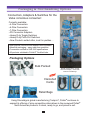
AUTOMOTIVE, MARINE, RECREATIONAL VEHICLES, TRUCKS
12 Volts, 15 Amps. Molded Inline connectors (Flat Type) are an economical means of connecting electrical systems.
Wires are color coded for easy installation. Standard 18 gauge automotive wire, 12 " wire length, except where noted.
Polarized design to insure proper connection. Molded case offers all-round weather protection.
FLAT TYPE
12-200
2-Pole Complete Assembly,
18 gauge wire.
12-404
4-Pole Complete Assembly with
48" wire leads of female (car) side.
12" leads on male (trailer) side
12-403
4-Pole Complete Assembly,
18 gauge wire.
SQUARE TYPE
12-600
6-Pole Complete
Assembly 18 gauge wire.
12-601
6-Pole Complete Assembly
with 48" wire leads on female (car)
side. 12" leads on male (trailer) side.
12-300
3 Way Male to Female
12” Loop
12-500: 5 Way Flat Female 60”
12-501: 5 Way Flat Male 60”
12-400: 4 Way Boot Cap
12-401: 4 Way Flat Female 12”
12-425: 4 Way Flat Female 48”
12-421: 4 Way Flat 12” Loop
12-412: 4 Way Flat 24” Loop
12-422: 4 Way Flat 36” Loop
12-423: 4 Way Flat 48” Loop
12-413: 4 Way Flat 60” Loop
12-414: same as 12-413 with boot covers
(all parts above are 4 Way Male to Female)
13
12-418: 4 Way Flat Male 12”
12-424: 4 Way Flat Male 48”
12-419: 4 Way Flat Male 12” Wishbone
12-405: 4 Way Flat Male 24” Wishbone
12-415: 4 Way Flat Male 36” Wishbone
12-417: 4 Way Flat Male 48” Wishbone
12-402: 4 Way Flat Female 48” Wishbone
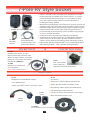
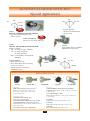
7-Pole RV Style Socket
11-893 - RV Socket 12V, 30 Amps
12-711U
Mounting
Bracket
11-998
Interlocking mating
connector to the 11-893
Socket and 4’ Harness.
Pollak‘s® sealed RV socket is designed to be dependable in one of the
harshest mounting environments for an electrical device - an exposed
external mounting under the rear bumper of a sport utility or pickup
truck. This connector design continues to earn the distinction of
becoming the industry standard.
Manufactured from high-impact nylon that solves corrosion problems and
eliminates rusting when mated with special interlocking sealed connector.
Socket lid features stainless spring and runner gasket to guarantee against
moisture intrusion when closed. Socket lid also designed with slot to
prevent sand and dirt from impairing closure and lid has wiring diagram
on cover to facilitate installation.
Socket lid also has a drain slot and is angled down for drainage.
Terminal pins are tin plated copper alloy providing higher conductivity
and less resistance and are sealed at the back of socket with silicone
sealant to prevent moisture from making contact with mating connector.
Fits Ford style and new universal Pollak® 12-711U mounting bracket for
other OEM applications. NEW – Includes mounting hardware.
SOCKET KITS
&
7-Pole RV Style Socket
11-898P
Includes 11-893 Socket, 12-711U
Bracket, Interlocking Connector and 4’
Harness assembly with 0.5” convoluted
tubing, and 7-wire leads color coded to
RVI Standard (SHOWN)
11-916
New ‘twist and lock’
socket, suitable as a
replacement for Pollak OEM sockets.
11-990P
Includes 11-893 Socket and
12-711U Bracket
NEW – Includes mounting hardware.
ADAPTERS
11-933
11-932
T-Connector
Rectangular-To-Round Harness Adapter.
Adaptor for 5th Wheel & Bumper Mount Socket
Fits OEM Harnesses.
Quickly & Easily Installs a Second RV Socket
Mates with Pollak® Socket 11-893 and 11-932P
Plug and Play without Splicing into OEM Harness
Fits GM and Ford Trucks and SUV’s
11-893
Socket
Fits Chrysler Trucks when used with 11-933 Adapter
Mates with Pollak® Socket 11-893
11-933
Adapter
11-938 Kit
11-893 Socket & 11-932 T-Connector
14
7-POLE CONNECTOR
12-705 Series (7-Pole Set) Black Pollak® Plastic
12-705
Complete Set (12-707 and 12-706)
12-706
Trailer-End Only Plug
12-707
Car-End Only Socket
12-709
12-705 Plug & Socket with 12-711U Bracket
12-712
12-707 with a 12-711U Bracket
Plastic connector set eliminates rusting, poor appearance and difficulty
in plug removal. Design offers dual grips for ease of plug removal from
socket and incorporates vinyl inserts to keep out dirt and moisture.
Interior design prevents internal short-circuiting, and the safety latch
prevents damage from accidental pull-away. Color coded to RVI
standards
12-700 Series (7-Pole Set) Metal
12-700
12-703 Socket & 12-702 Plug
12-702
Trailer-End Only Plug
12-703
Car-End Only Socket
12-704
12-700 Plug & Socket with 12-701U Bracket
12-710
12-703 with a 12-701U Bracket
12-706
Trailer End
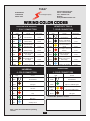
RECOMMENDED WIRE GAUGE
No.
Color
Gauge
Description
1
White
10
Ground Return
2
Blue
12
Electric Brake
3
Green
14
Tail, License and Running
Lights
4
Black
10
Battery Charge
Red
14
Stop & Left Hand Turn Signal
Brown
14
Stop & Right Hand Turn
Signal
Yellow
14
Auxiliary Circuit
12-707 5
Car End 6
12-702
Trailer End
Traditional metal connectors. Heavily plated for maximum weather and
corrosion resistance. Stainless steel cover spring. Jumbo welded pistol
grip. Unique safety latch prevents damage from accidental pull-away.
Specially designed vinyl inserts keep out dirt and moisture. Color coded to
RVI standards.
12-703
Car End
7
UNIQUE INTERIOR DESIGN
ELIMINATES SHORTING OUTNon-corroding, shock-resistant
interiors with unique terminal
reinforcer dams that eliminate
short circuiting by preventing
contact from spreading.
Center pin will take up to
8-gauge wire for battery charge system.
9-POLE CONNECTOR
Staking methods proven in long term usage. No possibility of molding
compound contaminating contacts to cause "dead spots”.
Unique method of machining from solid bar (not stamping) and spring
loading contacts give long trouble-free service. Over 1.5 million trucks
utilize this type of heavy duty connector contacts.
"Floating Pins" originating with POLLAK® and a standard for the
trucking industry are self-aligning offering continuous wiping action and
the most positive contact.
Terminals designed for 2-8 gauge, 2-12 gauge and 5-14 gauge to new
industry standard for minimum voltage drop.
Contacts on BOTH trailer and car side spring loaded. Completely FIELD
serviceable.
RECOMMENDED WIRE GAUGE
12-907
Car End
12-906
Trailer End
12-905 Series (9-Pole Set)
12-905
Complete for towing vehicle and trailer side
12-906
Trailer Side
No.
Color
Gauge
Description
12-907
Towing vehicle side
1
White
8
Ground Return
12-701U
Bracket for towing vehicle
2
Blue
12
Electric Brake
3
Green
14
Tail, License and Running Lights
4
Black
8
Battery Charge
5
Red
14
Stop & Left Hand Turn Signal
6
Brown
14
Stop & Right Hand Turn Signal
7
Yellow
14
Back-Up, Auxiliary Ground or Circuit
8
Gray
12
Auxiliary Circuit
9
Orange
14
Reefer (Tag) or Stop
MOUNTING BRACKETS
Right Angle Mounting Brackets for: 11-893. 12-703,
12-707, 12-907 NEW – Includes mounting hardware.
15
12-711U
Black Epoxy
Coated for
protection
against rust
and corrosion
12-701U
Constructed of
Heavy Gauge
Steel. Same as
12-711U but
without black
epoxy finish.
Trailer Tow Accessories
TRAILER WIRING TIPS
Avoid splices wherever possible * Establish a solid electrical ground * Maintain clean and weatherproof wire connections
* Make sure that the various wires and harnesses are free of stress and are not dragging or likely to be snagged *
12-717 Connector Adaptor (6-Pole to 4-Pole)
Converts 6-Pole Round Connector to a 4-Pole molded connector.
Quick and easy to connect.
Non-corrosive nylon shell and insert.
Eliminates makeshift jumpers.
12-716 Connector Adaptor (7-Pole to 4-Pole)
Converts 7-Pole Blade Connector to a 4-Pole molded connector.
Allows one vehicle to tow either campers or boat trailers without
electrical brakes.
Connects ground, L.T., R.T., and Stop Circuits.
Tethered cap for protection from sand, dirt or moisture intrusion.
Non-corrosive nylon shell and insert.
Eliminates makeshift jumpers.
12-744 Connector Adaptor (7-Pole to 5-Pole; not shown)
12-718 Connector Flex Adaptor (7-Pole to 5-Pole)
Converts 7-Pole Blade Connector to a 5-Pole molded connector.
Allows one vehicle to tow either campers or boat trailers with electrical
brakes.
Quick and easy to connect.
Full-length plug shell insures positive latching.
Non-corrosive nylon shell and insert.
12-743 Connector Flex Adaptor (7-Pole to 4-Pole; not shown)
12-719 & 12-729 Connector Adaptor (7-Pole to 6-Pole)
Converts 7-Pole Blade Connector to a 6-Pole Round Connector Plug.
Allows one vehicle to tow either campers or Utility trailers.
Quick and easy to connect.
Non-corrosive nylon shell and insert.
12-719 Adapter had brake pin in center of 6-Pole (Shown)
12-729 Adapter has auxiliary pin in center of 6-Pole
11-932 T-Connector
Adaptor for 5th Wheel & Bumper Mount Socket
Quickly & Easily Installs a Second RV Socket
Plug and Play without Splicing into OEM Harness
Fits GM and Ford Trucks and SUV’s
Fits Chrysler Truck when used with 11-933 Adapter
Mates with Pollak Socket 11-893
11-933 Rectangular-To-Round Harness Adapter
Fits OEM Harnesses.
Mates with Pollak® Socket 11-893 and 11-932
Cable Assembly (Repairable)
12 Volt Adapter
12 Volt Power When You Need It
“The Tailgater’s Best Friend”
11-896
Power Adapter plugs into any
7-Pole Blade Connector to
provide 12 volts of power
14-117
Pollak® Plastic Trailer End
12-706 with 8 ft. of Cable.
14-116: same as 14-117
but with 3 ft. of Cable
16
Trailer Tow Accessories
Adapters
7 Way Pin Plug to 12-724
7 Way RV Type Socket
12-411
4 Way Pin Plug to
4 Way Flat Flex Adapter
6 Way Round Plug to 12-725
7 Way RV Type Socket
12-611
6 Way Round Male to 4 Way
Flat Female Flex Adapter
4 Way Flat Plug to 12-610
6 Way Round Metal Socket
12-723
4 Way Flat Plug to
7 Way RV Type Socket
12-625
12-726
4 Way Flat Plug to
7 Way Round Metal Socket
6 Way Round Plug to
5 Way Flat Adapter
12-742
7 Way Pin Plug to
4 Way Flat Adapter
12-727: Nylon 7 way RV plug to 7 Way HD Socket
12-728: Nylon 7 Way RV Plug to Zinc 7 Way HD Socket
Heavy Duty 60”
12-750
7 Pin Circuit
Regular Duty 60”
12-751
4 Pin Circuit
12-741
12-410
17
18
SWITCHES
SWITCHES
Custom Designed Toggle
Available with Chrome
Plated or Black Matte
Finish
50 AMPS 6-24 VOLT TOGGLE SWITCHES
Pollak® Toggle Switches designed for many high-current applications.
Oversized internal copper contacts will carry up to 50 AMP current loads.
Provides the longest possible service life. (Note: Quick-Connect Blade
terminals will carry 30 AMPS.)
Aluminum
Knurled Face
Nut
Nickel Plated
Hex Nut
Rugged Glass
Filled Nylon
Slide and DieCast Body
Copper Contact
Bridge
.22 diameter Copper
Contacts
34-216
Standard
Chrome Handle
(Quick-Connect
Terminals)
Part No.
34-220
Long Chrome
Handle #8-32
Screw Terminal
No. of
Terminals
Circuitry
Brass Terminals (.312
Wide) Riveted to Base
to handle 3 in-lb
torque
Laminated
bakelite base
Plated Combination
Head #8-32 Screws
Terminal
Type
Handle
Length
Handle
Type
DC
Volts
DC
Amps
S.P.S.T (SINGLE POLE – SINGLE THROW)
34-212
On-Off
2
Screw
Std. 1”
Chrome
12
50
34-213
On-Off
2
Screw
Long 1.5”
Chrome
12
50
34-216
On-Off
2
Blade
Std. 1”
Chrome
12
30
34-219
On-Off
2
Screw
Std. 1”
Black
12
50
34-226
On-Off
2
Blade
Std. 1”
Black
12
30
34-225
On-On
3
Screw
Std. 1”
Chrome
12
50
34-218
On-Off-On
3
Screw
Std. 1”
Chrome
12
50
34-222
On-Off-On
3
Screw
Std. 1”
Black
12
50
S.P.D.T (SINGLE POLE – SINGLE THROW)
34-215
Mom On-Off-Mom On
3
Screw
Std. 1”
Chrome
12
50
34-223
Mom On-Off-Mom On
3
Screw
Std. 1”
Black
12
50
34-220
Mom On-Off-Mom On
3
Screw
Long 1.5”
Chrome
12
50
NYLON HANDLE DECORATOR STYLE 20 AMPS AT 12 VOLTS DC TOGGLE SWITCHES
Decorator style toggle switches designed with an O-Ring seal between toggle and bushing for splash proof reliability. Durable nylon housing, nylon face
nut and brass terminals resist corrosion. Lighted versions have transparent Lexan handle. 20 AMPS @ 12 VDC.
34-586Q
.250 Blade
Terminals
Part No.
34-586Q
Circuitry
No. of
Terminals
Terminal
Type
34-588
Handle
Length
Handle
Type
S.P.S.T ( SINGLE POLE – SINGLE THROW )
34-581Q
On-Off
2
Blade
Std. 11/16”
Black
34-586
On-Off
4
Screw
Std. 11/16”
Lighted
34-586Q
On-Off
4
Blade
Std. 11/16”
Lighted
.072X.038 KEYWAY
KNURL NUT
FACE PLATE
S.P.D.T ( SINGLE POLE –DOUBLE THROW )
34-588
On-Off-On
5
Screw
Std. 11/16”
Lighted
34-588Q
On-Off-On
5
Blade
Std. 11/16”
Lighted
Q = Quick Connect .250 Terminals
(See page 23 for Circuit Diagrams)
15/32-32 THREAD
19
HEX NUT
SWITCHES
A complete selection of circuitry configurations for Truck, Off-Road, Automotive and Recreational Vehicle applications.
Provides durable and long lasting solutions to new and replacement requirements. 20 Amps @ 12 VDC.
Part No.
No. of
Terminals
Circuitry
Terminal
Type
Handle
Length
Handle
Type
Notes
S.P.S.T ( SINGLE POLE – SINGLE THROW )
33-302
On-Off
2
Screw
Std. 11/16”
Chrome
34-571
On-Off
2
Screw
Std. 11/16”
Chrome
34-571Q
On-Off
2
Blade
Std. 11/16”
Chrome
34-571L
On-Off
2
Screw
Long 1.5”
Chrome
34-571LQ
On-Off
2
Blade
Long 1.5”
Chrome
34-579
On-Mom Off
2
Screw
Long 1.5”
Chrome
34-579Q
On-Mom Off
2
Blade
Long 1.5”
Chrome
34-570
Mom On-Off
2
Screw
Std. 11/16”
Chrome
34-570Q
Mom On-Off
2
Blade
Std. 11/16”
Chrome
S.P.D.T ( SINGLE POLE – DOUBLE THROW )
34-572
On-On
3
Screws
Std. 11/16”
Chrome
34-572Q
On-On
3
Blade
Std. 11/16”
Chrome
On-Off-On
3
Screw
Std. 11/16”
Chrome
34-573
On-Off-On
3
Blade
Std. 11/16”
Chrome
34-575
34-573Q
Mom On-Off-Mom On
3
Screw
Std. 11/16”
Chrome
34-575Q
Mom On-Off-Mom On
3
Blade
Std. 11/16”
Chrome
34-653
Mom On-Off-Mom On
3
NEW
New
Std. 11/16”
Chrome
34-596
On-Off-Mom On
3
Screw
Std. 11/16”
Chrome
.56
1.13
Coated 8”
wire leads
D.P.S.T. ( DOUBLE POLE – SINGLE THROW )
34-574
On-Off
4
Screw
Std. 11/16”
Chrome
34-574Q
On-Off
4
Blade
Std. 11/16”
Chrome
34-571L
34-592Q
Long Handle Jumper Blade
Screw Terminals
Style
D.P.D.T. ( DOUBLE POLE – DOUBLE THROW )
34-576
On-On
6
Screw
Std. 11/16”
Chrome
34-576Q
On-On
6
Blade
Std. 11/16”
Chrome
34-577
On-Off-On
6
Screw
Std. 11/16”
Chrome
34-577Q
On-Off-On
6
Blade
Std. 11/16”
Chrome
34-577LQ
On-Off-On
6
Blade
Long 1.5”
Chrome
Mom On-Off-On
6
Screw
Std. 11/16”
Chrome
34-578
34-578Q
Mom On-Off-On
6
Blade
Std. 11/16”
Chrome
34-580
Mom On-Off-Mom On
6
Screw
Std. 11/16”
Chrome
34-580Q
Mom On-Off-Mom On
6
Blade
Std. 11/16”
Chrome
34-580L
Mom On-Off-Mom On
6
Screw
Long 1.5”
Chrome
WIRING DIAGRAMS
34-591Q
34-593Q
34-580LQ
Mom On-Off-Mom On
6
Blade
Long 1.5”
Chrome
34-591Q
Mom On-Off-Mom On
4
Blade
Std. 11/16”
Chrome
Reversing
34-591LQ
Mom On-Off-Mom On
4
Blade
Long 1.5”
Chrome
Reversing
On-On
6
Screw
Std. 11/16”
Chrome
Reversing
34-592Q
On-On
6
Blade
Std. 11/16”
Chrome
Reversing
34-593LQ
On-Off-On
6
Blade
Long 1.5”
Chrome
DHP Circuits
Headlamp Switch
34-592
20
Q = Quick Connect .250 Terminals L = Long Handle 1.5”
(See page 23 for Circuit Diagrams)
ACCESSORIES
The best combination of space-saving size and economy. Universal for Automotive, Light Truck, Off-Road and
Recreational vehicles. Furnished with mounting hardware.
33-300
2 Position Toggle Switch, On-Off
6 Volt-35 Amps 12 Volt-20 Amps
Brass construction. Screw terminals.
Toggle and Face Nut CHROME
PLATED, Mounting Stem 3/8"
Long, 7/16" diameter
34-500
2 Position Toggle
Switch, 20 Amps @ 12
VDC, S.P.S.T. Knurled
Face Nut Indicator
Plate, Back Nut and
Terminal Screws
assembled.
25-370
Toggle Boot with 15/32-32 thread. Provides
protection against salt spray and is resistant to
weather and ozone. Can be used on toggle
switches with 15/32" diameter mounting stem.
25-371
1/2 Toggle Boot
Same as Toggle Boot #25-370 except allows
Toggle Handle (of any length) to protrude.
Accommodates all toggle lever diameters
from .155" - 240" including all Pollak toggles
except nylon handle series.
34-504
Face Plate On-Off
34-513
2 Position Toggle
Switch. 10 Amps @
12V
See Page 23 For Wiring
Diagrams, Terms and Tips.
UNIVERSAL DESIGN ROCKER SWITCHES - 20 AMPS AT 12 VDC
Internal and
External
Features
Universal Design for Automotive,
Truck, Bus, Marine &
Recreational Vehicles. Snap-in
mounting fits .830 x 1.450 panel
cutout in .093, .125, .187 thick
panels. Brass screw or .250 blade
terminals. Nylon bezel actuator
and housing.
Nylon Actuator
Copper Contact
Lever
Silver contacts
Copper Lever Cage
Solid Brass Terminals
Part No.
Circuitry
WIRING DIAGRAM
34-305
Rugged Black
Nylon Rocker.
Bezel and
Housing
No. of
Terminals
and Type
Actuator
Lens
Solid Brass Slot
Head #6-32
Screws
Notes
Application
S.P.S.T. ( SINGLE POLE – SINGLE THROW)
34-301
On-Off
2 Screw
Black
Signaling Switch, Day
34-308
On-Off
2 Blade
Black
Signaling Switch, Day
34-305
On-Off
3 Screw
Black
Red
Red Pilot Light
34-360
On-Off
3 Blade
Black
Red
Red Pilot Light
34-306
On-Off
3 Screw
Black
Green
Green Pilot Light
34-307
On-Off
3 Screw
Black
Amber
Amber Pilot Light
34-310
On-Off
4 Blade
Black
Red
Red Pilot Light
34-359
S.P.S.T. ( SINGLE POLE – SINGLE THROW) WITH PILOT LIGHT
D.P.D.T. ( DOUBLE POLE – DOUBLE THROW )
34-311
Off-On-On
4 Blade
Black
34-359
On-On
6 Blade
Black
34-312
High-Low-Off
Two Speed Windshield Wiper
Reversing
Selector Valves, Fans, Booms
D.P.D.T. ( DOUBLE POLE – DOUBLE THROW ) WITH DUAL CIRCUITRY
6 Blade
Black
See Page 23 For Wiring Diagrams, Terms and Tips.
Dual Actuators
High-Low-Off
21
34-305
SWITCHES
SEALED ILLUMINATED ROCKER SWITCHES
Designed for complete protection against dust and moisture.
Rated 20 Amps at 12 VDC.
Features include black plastic housing, nylon bezel, silver contacts, white lens
34-230
(Shown)
with LED bulb, and .250’ quick connect terminals.
May be used with Pollak’s new single and modular mounting brackets.
(Panel cut-out dimension: .83 “ W x 1.45” H)
34-230
On-Off, S.P.S.T
34-236
Mom. On-Off-Mom. On, S.P.D.T.
34-231
Mom. On-Off, S.P.S.T.
34-237
On-On, D.P.D.T.
34-232
Off-On-Off, S.P.S.T.
34-238
On-Off, D.P.S.T.
34-233
On-On, S.P.D.T.
34-239
Mom .On-Off-Mom. On, D.P.D.T.
34-234
On-Off-On, S.P.D.T.
34-240
Off-On-On, Progressive
34-235
On-On-On, S.P.3.T.
34-241
On-On-Mom. On, Progressive
ROCKER SWITCHES MOUNTING BRACKETS
New Modular mounting brackets and single mounting bracket #34-260 (Not shown) for
use with installing Pollak’s ® new rocker switches #34-230 Series (Shown above).
To be used when installing rocker switches in panels.
Stackable mounting end brackets #34-258 are reversible and can be connected
to either side of middle bracket #34-259.
34-258
34-259
34-260
34-258
34-255
Single mounting bracket #34-260 may be used for a single switch mount.
34-255
Panel Gasket Seal
34-258
Mounting Bracket End Piece
34-259
Mounting Bracket Middle Piece
34-260
Single Mounting Bracket
WEATHER RESISTANT TOGGLE SWITCH
34-571C
Weather resistant plastic coating with O-Ring in stem.
2 Positions: On-Off, S.P.S.T., Rated 20 Amps, 12 VDC
Knurled face nut, hex back nut, and 2 plastic coated wire leads 8” long.
Chrome plated bat handle, mounting stem 15/32 diameter., 3/8” long.
34-111 Same as 34-571C except with 2 plastic coated wire leads 24” long.
TOGGLE SWITCH GUARD
Spring loaded snap action holds the guard cover in the up or down position.
Switch cannot be operated with the cover in the down position.
34-508
Recommended for use with two position (Off-On or On-On) toggle switches
with standard 11/16” bat handle and 15/32” diameter mounting stem and keyway.
Face plate is steel with black glossy finish. Switch cover coated with red urea.
22
D.P.D.T. (Double Pole/Double Throw)
A six terminal switch that controls two double wire circuits
permitting only one circuit to be energized at a time, or four
single wire circuits permitting only two circuits to be energized
at a time.
S.P.S.T, (Single Pole/Single Throw)
A two terminal switch which opens or closes one circuit.
Two Positions On-Off
(common)
LOAD
(common)
(common)
RET
LOAD #1
LOAD #2
(COMMON) SOURCE
LOAD #4
ON
-
OFF
(ON)
-
OFF
ON
(ON) = MOMENTARY (OFF) = MOMENTARY
(COMMON) SOURCE #2
RET #3
RET #1
(COMMON)
THREE POSITION On-Off-On
(Common)
LOAD #1
(Common)
TWO POSITION
On-On
LOAD #2
-
ON
ON- OFF- ON
Three Position On-off-On
(COMMON) SOURCE
ON- OFF- ON
(Common)
(ON)- OFF- ON (ON)-OFF-OM
ON -
OFF -
ON
(Common)
(ON) - OFF - (ON)
(Common)
(Common)
ON - ON
ON - ON
(Common)
(Common)
(Common)
RET #1
(Common)
RET
(COMMON) SOURCE
(Common)
ON
LOAD #2
LOAD #1
LOAD #3
S.P.D.T. (Single Pole/Double Throw)
A three terminal switch that controls two single-wire circuits. Permits
only one circuit to be energized at a time
RET #2
RET #4
(COMMON) SOURCE #1
- ( OFF)
Two Position On-On
RET #2
(ON)- OFF- (ON) (ON)-OFF-(ON)
(ON) = MOMENTARY
(ON) = MONEMTARY
ELECTRICAL TERMS
D.P.S.T. (Double Pole/Single Throw)
A four terminal switch that controls one double wire circuit or two
single wire circuits.
Two Positions On-Off
Two single wire circuits.
Two Positions On-Off
One double wire circuit
LOAD #1
RET #2
LOAD
LOAD #2
RET #2
(COMMON)
(COMMON) SOURCE #2
(COMMON)
RET
SOURCE
(COMMON) SOURCE #1
(COMMON)
ON - OFF ON - OFF
(COMMON)
(ON) - OFF (ON) - OFF
(ON) = MOMENTARY
SERVICE TIP
Replacement switch must have the same or higher rating as
original switch.
Unplug circuit or turn off power at electrical panel.
Remove wires from old switch one-at-a-time and attach to
new switch in same manner, or follow wiring diagram.
For Screw Terminals - Twist stranded wire together. Loop
wire clockwise around screw . Tighten securely.
For Blade Terminals - Use Female push-on terminals. Crimp
tightly on stranded wire. Make sure you have a snug fit.
Turn on power
23
AMPERE Electrical unit indicating rate of flow of electricity through
a circuit.
CIRCUIT Path taken by electrical current flowing through conductor
from one terminal source of supply to another.
CURRENT The movement of electrons through a conductor measured
in amperes.
DOUBLE POL£ A switch that operates simultaneously in two separate
electric circuits.
DOUBLE THROW A switch that alternately completes a circuit at
either end of its extreme positions.
DOUBLE POLE/SINGLE THROW D.P.S.T -A switch that
has four terminals and is used to connect or disconnect two pairs of
terminals simultaneously.
DOUBLE POLE DOUBLE/THROW D.P.D.T A switch that has six
terminals and is used to connect one pair of terminals to either of the other
two pairs.
INDUCTIVE LOAD Initial amps needed to engage a circuit and/or a
load which allows a momentary flow of current when a circuit is open.
{Devices that create inductive loads are typically motor coils and
solenoids.)
LAMP LOAD Light bulb current expressed in amps at a rated voltage.
MONENTARY Momentary action is obtained by holding switch in
position with pressure. Upon release the switch returns to the previous
position.
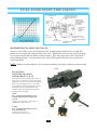
REVERSING Reversing action is obtained by reversing the polarity of
a switch with jumper wires or blades to change the rotation of a motor.
Typical applications are winches, plows, radio antennas and fuel selector
valves.
SINGLE POLE A switch that opens, closes, or changes connection in a
single conductor of an electrical circuit to a common contact.
SINGLE THROW A switch that opens, closes or completes a circuit at
only one of the extreme positions of its actuator.
SINGLE POLE/SINGLE THROW S.P.S.T. - A two terminal switch
which opens or closes one circuit.
SINGLE POLE/DOUBLE THROW S.P.D.T. - A three terminal
switch for connecting one terminal to either of two other terminals.
VOLT The unit that measures the potential difference in electrical force
or "pressure" between two points on a circuit.
WATT The unit of power that indicates the rate at which a device
converts electric current to another form of energy, either heat or motion.
SWITCHES - PUSH-PULL
.88 DIA
.66
2.12
1.44
35-331
35-306
..56
35-330
35-316
35-306
6-28 VOLTS - 75 AMP D.C. 2 POSITION
S.P.S.T. OFF-ON Die-Cast Body, CHROME
PLATED, Knob, Copper Terminals, Mounting
Stem 5/8” long, 15/32” Diameter
35-300
35-331
Same as 35-306 with Red Metal Knob
52-642
Mating Connector
35-320
35-330
Same at 35-306 with Black Metal Knob
35-319
Same at 35-306 except the hardware is
assembled on the switch.
35-316
3 POSITION
12V OFF-ON-ON Combination
Rheostat, Panel and Headlight. Push
Pull for Headlights, Turn to Dim
Panel. With 20 Amp Circuit Breaker, 5
Terminals, Bright Metal Knob,
Mounting Stem 3/8" Long, 3/8"
diameter.
35-300
2 POSITION
OFF-ON 25 Amp at 6V
15 Amps at 12V. Mounting Stem 5/8"
Long 7/16" diameter. Ivory Plastic Knob.
MARINE
33-400
3 POSITION
OFF-ON-BOTH ON FOR
CONTROLING RUNNING
LIGHTS, etc. Large 3/4"
diameter. Face Nut of
POLISHED CHROME.
Brass Back Nut and Washer.
CHROME PLATED plastic
knob. Mounting Stem
l-l/4"Long 7/16" diameter.
33-402
2 POSITION 25 Amps at 6V
15 Amps at 12V
OFF-ON POLISHED
CHROME Face Nut and
CHROME PLATED plastic
knob. Brass Back Nut and
Washer. Mounting Stem
1-1/4" Long, 3/8" diameter.
24
2 Position Off-On (Normally Off) –
One Circuit. Rugged Nylon
housing and mounting bracket.
Bushing .59” long, .59 diameter
Silver plated brass terminals mate
with Mating Connector #52-642.
Panel mount or transmission shaft
mount (when used as a single speed
axle switch)
33-400
33-402
33-403
33-403
3 POSITION
OFF-ON-ON Two Separate Circuits.
Brass Back Nut and Washer.
BRASS CHROME PLATED Knob
and Face Nut. Mounting Stem 1-1/4"
Long, 3/8" diameter.
25
SWITCHES
BOOT NUT ASSEMBLIES
WEATHER and DUSTPROOF Neoprene rubber type Boot Nut Assemblies. With 5/8-32 thread,
Can be used on #52-611 and #33-200 and on other Momentary Switches with this Mounting Stem
25-372
Protective Collar - Safety Bezel with
5/8"-32 thread may be used on #24359, #52-611, #33-200 and on other
momentary switches with this
mounting stem.
25-358
Black
25-352
Red
25-350
25-351
Yellow boot with
Same as 25-358 except recessed “cold start “
with recessed “horn”
symbol.
symbol.
25-349
Same as 25-352 except
with recessed “start”
symbol.
52-611
Universal-Mounting Bushing
3/4"Long, 5/8"diameter. Hex
Pal Back Nut knurled Face Nut
assembled. 25 AMPS @ 6V, 15 AMPS
& 12V. Mounts in 5/8 "diameter hole.
52-600
REPLACES: 21A11500A, Screw
Terminals. 15 AMPS @ 6V, 10
AMPS @ 12V, 15/16” Mounting
Hole Required. Mounting Stem
7/8”-20, .45” long. Supplied with
7/8”-20 palnut.
52-613
Same as 52-611 except with
25-358 boot nut and PVC coated
body for weather and dust
protection. 14” wire loop.
MOMENTARY SWITCHES
SEALED PLUNGER SWITCHES
2 Positions: On- Off Normally On (Push to Off)
2 Positions: On- Off
Normally On (Push to Off)
52-622
21-541
Momentary Switch -Normally On (Push to
Off). Moisture Proof with two 6" 16 gauge
wire leads with Packard Electric Connector
#12010973. Mates with Packard #12015792.
52-620
52-624
Sealed Plunger Switch #52-620 and Mating
Connector #52-622. 10 Amps at 14V. Self tapping
thread. Self-Adjusting, Switch length 2 1/8“. Mating
connector has three 8" 18 gauge wire leads.
21-560
Same as 21-541 except Normally Closed (Push
to On). Mates with Packard # 15300027
MARINE
15 Amps at 12V
52-623
Door Jamb Switch to accept two
Bullet terminals. 5 Amps at 12V.
REPLACES: Ford OA1-13713,
BOA-13713, B9MF-13713A,
C3AZ-13713A.
33-200
ALL BRASS, CHROME PLATED Button and
Face Nut Furnished. Brass Back Nut and Washer
Mounting Stem 1 1/4" Long 5/8” diameter.
25 Amps @ 6V. Fits 1" thick panel.
26
Cold-rolling steel body, zinc plated
and enhanced with chromate coating,
provides strength and environmental
resistance to surpass application
requirements.
PRECISION BALL
SWITCHES
As the leading manufacturer of
precision ball-actuated switches,
Pollak® has provided custom switches
to meet the requirements of OEM's and
aftermarket suppliers. Typical
applications include: neutral and top
gear sensing, back-up lamp switching,
anti-lock brake switching, power takeoff interlock and operator presence
detecting. The switches shown here
represent the transportation industry’s
most commonly requested
configurations. If the switch you need
cannot be found on these charts, please
contact us for your specific
requirements.
CHARACTERISTICS:
Normally Open - Exposed Terminals
Premium grade silicone gasket and
Teflon diaphragm prevent moisture
and other contaminants from entering
the contact chamber.
Free-rolling chrome steel
ball accommodates most
rail, cam and lever
actuators
Precision over-travel
mechanism assures
contact under all
operation conditions.
Connectors/ terminations
match preferred OEM
termination and harness
practices.
All contacts are silver plated
ETP copper for contact
reliability and long life.
21-458
Screw Terminals
21-481
Turret Terminals
Part
No.
Thread
Hex
Free Position
Make/Break
Connector
Terminals
21-361
9/16-18
7/8
.421 / .416 (10.69-10.57)
.406 / .391 (10.31-09.93)
Stud Terminals
21-381
9/16-18
7/8
.765 / .760 (19.43-19.30)
.730 / .715 (18.54-18.16)
Turret Terminals
21-458
9/16-18
7/8
.421 / .416 (10.69-10.57)
.408 / .390 (10.36-09.93)
Screw Terminals
Ring Terminals
21-481
9/16-18
7/8
.421 / .416 (10.69-10.57)
.408 / .390 (10.36-09.93)
Turret Terminals
PE 02973407
21-487
9/16-18
7/8
.421 / .416 (10.69-10.57)
.408 / .390 (10.36-09.93)
Screw Terminals
Ring Terminals
21-509
3/4-16
7/8
.577 / .551 (14.15-14.00)
.533 / .513 (13.54-13.03)
Screw Terminals
CHARACTERISTICS:
Normally Closed - Exposed Terminals
21-456
.250 Blade
Terminals
Mating
Connector
Special Features
21-458 with O-Ring
21-517
.250 Blade
Terminals
Part
No.
Thread
Hex
Free Position
Make/Break
Connector
Terminals
Mating
Connector
21-434
9/16-18
7/8
.421 / .416 (10.69-10.57)
.408 / .390 (10.36-09.93)
Turret
PE 02973407
21-435
9/16-18
7/8
.421 / .416 (10.69-10.57)
.408 / .390 (10.36-09.93)
Screw
Ring Terminals
21-437
9/16-18
7/8
.421 / .416 (10.69-10.57)
.408 / .390 (10.36-09.93)
Screw
Ring Terminals
Plating
21-448
3/4-16
7/8
.606 / .601 (15.39-15.27)
.600 / .384 (15.24-14.86)
Screw
Ring Terminals
Aluminum Washer resist Corrosion
21-456
9/16-18
7/8
.421 / .416 (10.69-10.57)
.408 / .390 (10.36-09.93)
.250 Blade
Rect. Receptacle Term
21-517
9/16-18
7/8
.421 / .416 (10.69-10.57)
.408 / .390 (10.36-09.93)
.250 Blade
Rect. Receptacle Term
27
Special Features
21-456 With O-ring
CHARACTERISTICS:
21-370
Normally Open - Sealed Terminals
Special
Features
Part No.
Thread
Hex
Free Position
Make/Break
Connector
Mating Connector
21-363
9/16-18
7/8
.421 / .416 (10.69-10.57)
.406 / .391 (10.31-09.93)
Packard 56 Series
029S4092
21-364
9/16-18
7/8
.421 / .416 (10.69-10.57)
.408 / .390 (10.36-09.93)
Ford Automotive Type
C0AF-14A121-A
21-370
9/16-18
7/8
.421 / .416 (10.69-10.57)
.406 / .391 (10.31-09.93)
Packard Weather Pack
12015792
21-400
9/16-18
7/8
.421 / .416 (10.69-10.57)
.408 / .390 (10.36-09.93)
Ford Automotive Type
E2EB-14A464-AB
21-443
M14*1.5
M22
.460 / .450 (11-68-11.43)
.435 / .415 (11.05-10.54)
Ford Automotive Type
D6ZB-14A336-BA
21-465
9/16-18
7/8
.421 / .416 (10.69-10.57)
.406 / .391 (10.31-09.93)
Packard Metri-Pack
12052644
21-491
5/8-18
7/8
.433 / .417 (11.00-10.59)
.405 / .380 (10.29-09.65)
Packard Weather Pack
12103784
21-492
M14*1.5
M22
.577 / .567 (14.66-14.40)
.561 / .543 (14.25-13.79)
Packard Metri-Pack
12052644
21-532
9/16-18
7/8
.421 / .416 (10.69-10.57)
.406 / .391 (10.31-09.93)
Packard Weather Pack
12015792
Teflon Tape
Thread Sealant
21-595
M16*1.5
7/8
.980 / .970 (24.89-24.64)
.960 / .945 (24.38-24.00)
Packard Weather pack
12015792
Teflon Tape
Thread Sealant
Teflon Tape
Thread Sealant
CHARACTERISTICS:
Normally Closed - Sealed Terminals
Part No.
Thread
Hex
Free Position
Make/Break
Connector
Mating
Connector
21-444
5/8-18
7/8
.433 / .417 (11.00-10.59)
.405 / .380 (10.29-09.65)
Packard Weather Pack
12103784
21-495
9/16-18
7/8
.657 / .652 (16.69-16.56)
.644 / .625 (16.36-15.88)
Packard Weather Pack
12015792
21-538
M16*1.5
M22
.609 / .598 (15.47-15.19)
.594 / .579 (15.09-14.71)
Packard Weather Pack
12103784
Special Features
Assembled with O-Ring
CHARACTERISTICS:
Normally Open - Encapsulated with Wire Leads
Part No.
Thread
Hex
Free Position
Make/Break
Connector
Mating
Connector
21-467
9/16-18
7/8
.421 / .416 (10.69-10.57)
.408 / .390 (10.36-09.93)
Packard Metri-Pack
15300027
21-493
M14*1.5
M22
.577 / .567 (14.66-14.40)
.561 / .543 (14.25-13.70)
Packard Metri-Pack
12052644
21-562
9/16-18
7/8
.421 / .416 (10.69-10.57)
.406 / .391 (10.31-09.93)
Packard Metri-Pack
15300027
Special Features
CHARACTERISTICS:
Normally Closed - Encapsulated with Wire Leads
21-478
Part No.
Thread
Hex
Free Position
Make/Break
Connector
Mating
Connector
21-478
9/16-18
7/8
.421 / .416 (10.69-10.57)
.408 / .390 (10.36-09.93)
Packard Weather Pack
12010973
21-482
9/16-18
7/8
.421 / .416 (10.69-10.57)
.408 / .390 (10.36-09.93)
Packard Weather Pack
12010973
Assembled with O-Ring
21-547
9/16-18
7/8
.421 / .416 (10.69-10.57)
.408 / .390 (10.36-09.93)
Packard Metri-Pack
15300002
Assembled with O-Ring
28
Special Features
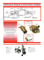
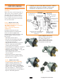
IGNITION STARTER SWITCHES
Momentary Start Universal Type Die-Cast Housing
COMMON
AVAILABLE SWITCH
CHARACTERISTICS
HIGH IMPACT
BASE
ONE PIECE ZINC DIE-CAST HOUSING
SPUN OVER TERMINAL BASE 360
SOLID COPPER CONTACTS & WIRING
INTERNALLY LUBRICATED FOR LONGER LIFE
LOCK CYLINDER & KEY
BRASS TERMINALS
MANY BASE
STYLES AVAILABLE
(SEE CHART)
HEAVY CHROME PLATED BRASS MOUNTING.
NUT, OTHER STYLES AVAILABLE
WEATHER
RESISTANT
O-RING SEAL
DRAIN HOLE
SECONDARY LIP SEAL MAXIMUM
PROTECTION AVAILABLE (SEE CHART)
PATENTED STARTER LOCKOUT FEATURE
PREVENTS RESTART OF RUNNNG VEHICLE
(SEE CHART FOR AVAILABILITY)
LIP SEAL PRVENTS MOISTURE FROM
ENTERING CONTACT CHAMBER
Typical Ratings @ 14 Volts DC (50,000 Cycles)
BASE TYPES & CONNECTIONS
TYPE 1
Ignition
Terminal
Accessory
Terminal
Start Terminal
8 Amps
30 Amps
(Inductive)
75 Amps make
20 Amps Break
TYPE 4
Continuous Current Carrying Capacity – 30 Amps @ 14V.
Accessory Terminal with #10 Gauge Wire.
For Specific Applications Consult Factory
TYPE 2
TYPE 3
TYPE 3A
TYPE 5
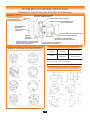
MOUNTING HOLE PATTERNS
STYLE 1
STYLE 2
STYLE 3
STYLE 4
STYLE 5
STYLE 6
TYPE 6
TYPE 7
For Specific Applications Consult Factory
Base Types (3, 3A & 7) fit Packard Connector #2984017
29
OFF
4-POSITION SWITCHES
ON / ACC
ACC
FUNCTIONS & POSITIONS
Key Removable in "Off" Position Only
START
(SPRING RETURN TO ON)
31-242
31-180
31-610
Base
Type
Part No.
Starter
Lockout
Key Logo
Key code
# of Lip
Seals
M/H/P
1
31-103
N
Pollak
Various
0
2
1
31-104
N
Pollak
PK556
0
2
1
31-105
Y
Pollak
Various
0
2
1
31-106
Y
Pollak
PK556
0
2
No L/Cyl
0
1
No Base Hardware Supplied
Various
0
1
No Base Hardware Supplied
No L/Cyl
0
1
No Base Hardware Supplied
Remarks
1
31-109
N
1
31-110
N
1
31-111
N
1
31-131
N
Pollak
Various
0
1
Spc. Hardware Clips
1
31-159
N
None
Special
1
3
Key Code 31-159-100
1
31-178
N
L/Cyl Mfg
D250
2
5
1
31-180
N
L/Cyl Mfg
Various
2
5
“O” Sealed Base
1
31-190
N
No Key
Universal
1
4
No Base Hardware or Keys Supplied
1
31-196
N
Pollak
Universal
1
4
Pollak
1
31-233
Y
No L/Cyl
0
2
1
31-292
Y
Pollak
Various
0
2
Black Mounting Nut
1
31-292-801
Y
Pollak
C801
0
2
Black Mounting Nut
1
31-292-802
Y
Pollak
C802
0
2
Black Mounting Nut
1
31-292-803
Y
Pollak
C803
0
2
Black Mounting Nut
1
31-292-804
Y
Pollak
C804
0
2
Black Mounting Nut
1
31-292-805
Y
Pollak
C805
0
2
Black Mounting Nut
1
31-292-806
Y
Pollak
C806
0
2
Black Mounting Nut
1
31-305
Y
L/Cyl Mfg
D250
2
5
1
31-607
N
Lever
0
2
1
31-608
Y
Lever
0
1
1
31-610
Y
Pollak
Universal
1
4
2
31-124
N
No L/Cyl
0
3
3
31-228
N
Pollak
Universal
2
31-242
Y
Pollak
Universal
1
4
3
31-132
N
L/Cyl Mfg
Various
0
Spc.
Spc. Hardware Clips
Terminal Ground ID Tag
Spc. Hardware Clips
Bezel Mfg.
M/H/P = Mounting Hole Pattern
30
4-POSITION SWITCHES
FUNCTIONS & POSITIONS
Key Removable in "Off" Position Only
OFF
ACC
ON / ACC
31-322
31-112
START
(SPRING RETURN TO ON)
(HOUSING TIED TO GROUND TERMINAL)
Key Logo
Key code
# of Lip
Seals
M/H/P
Pollak
D250
2
*
Spring return aux. / glow plug warmer
N
Pollak
PK556
0
2
Special Hardware Clips
31-257
Y
L/Cyl Mfg
D250
1
5
O-Ring Sealed Base, Spc. Hdw Clip
3
31-114
N
Pollak
Various
0
1
Caution Tag on GND Term
3
31-152
N
No L/Cyl
0
1
Caution Tag on GND Term
3
31-229
N
L/Cyl Mfg
D250
2
5
3
31-243
Y
Lever
1
5
3
31-249
N
Pollak
PK556
0
1
Caution Tag on GND Term
3
31-289
N
No L/Cyl
0
1
Caution Tag on GND Term
3A
31-290
Y
L/Cyl Mfg
D250
1
5
O-Ring Sealed Base
3A
31-322
Y
Encap key
D250
1
5
No Logo on Encap keys
3A
31-324
Y
L/Cyl Mfg
D250
1
5
Black Mounting Nut
3
31-498
N
None
Various
0
3
Supplied with high durability double cut L/Cyl & keys
3A
31-139
N
L/Cyl Mfg
Various
0
Spc.
3A
31-191
Y
L/Cyl Mfg
Various
1
5
O-Ring Sealed Base
3A
31-231
Y
L/Cyl Mfg
D250
1
5
O-Ring Sealed Base
3A
31-273
N
L/Cyl Mfg
Various
2
5
O-Ring Sealed Base
3A
31-280
N
None
Various
1
5
O-Ring Sealed Base, Mtg Nut Sold Separately
3
31-359
N
None
Various
0
3
Base Type
Part No.
1
31-527
2
31-112
2
Starter
Lockout
Remarks
New
Bezel Mtg
* - Mounting hole pattern similar to MHP style 5 without key way.
OFF
3-POSITION SWITCHES
ON / ACC
FUNCTIONS & POSITIONS
Key Removable in "Off" Position Only
Base
Type
Part No.
Starter
Lockout
1
31-119
N
Key Logo
1
31-122
N
1
31-192
N
Pollak
1
31-245
N
3
31-164
N
4
31-600
N
Pollak
7
31-223
Y
Lever
4
31-601
N
Pollak
L/Cyl Mfg
Base Types (3, 3a & 7) fit Packard Connector #2984017
31-600
Key code
# of Lip
Seals
M/H/P
No L/Cyl
0
1
Extra Long Studs in all Positions
Remarks
C805
0
1
No Base Hardware Supplied
No L/Cyl
0
1
No Base Hardware Supplied
D250
2
5
No Base Hardware Supplied, O-Ring Sealed Base
No L/Cyl
0
3
Mtg. Nuts Sold Seperately
Various
0
.75” D
0
5
0
.75” D
PK556
31
M/H/P = Mounting Hole Pattern
3 POSITION SWITCHES
FUNCTIONS & POSITIONS
Key Removable in "Off" Position Only
OFF
ON / ACC
31-297
31-267
START
(SPRING RETURN TO ON)
(HOUSING TIED TO GROUND TERMINAL)
Key code
# of
Lip
Seals
M/H/
P
L/CYL Mfg
D250
1
5
Y
Pollak
Universal
1
5
31-345
N
Pollak
Universal
1
4
3A
31-285
N
L/CYL Mfg
D250
2
5
3A
31-297
Y
Pollak
Universal
1
4
Base
Type
Part No.
Starter
Lockout
Key Logo
2
31-267
Y
2
31-302
2
Remarks
Black Mounting Nut, O-Ring Sealed Base
O-Ring Sealed Base
M/H/P = Mounting Hole Pattern
Base Types (3, 3A & 7) fit Packard Connector #2984017
3 POSITION SWITCHES
FUNCTIONS & POSITIONS
Key Removable in "Off" Position Only
OFF
ON / ACC
31-337
31-253
START
(SPRING RETURN TO ON)
Key Logo
Key
code
# of
Lip
Seals
M/H/P
N
Lever
D250
1
5
31-609
N
Blank
Various
0
2
3
31-309
Y
L/CYL Mfg
D250
1
5
3
31-337
Y
Pollak
D250
1
5
Base
Type
Part No.
Starter
Lockout
1
31-253
1
Base Types (3, 3A & 7) fit Packard Connector #2984017
TYPE 1
Remarks
O-Ring Sealed Base
M/H/P = Mounting Hole Pattern
TYPE 2
TYPE 3
TYPE 3A
TYPE 4
BASE
TYPES
MOUNTING
HOLE
PATTERNS
STYLE 1
STYLE 2
STYLE 3
32
STYLE 4
STYLE 5
2-POSITION SWITCHES
FUNCTIONS & POSITIONS
Key Removable in "Off" Position Only
OFF
ON
31-604
Key code
# of
Lip
Seals
M/H/P
Pollak
PK580
0
2
N
None
Various
0
.75”D
31-603
N
Pollak
PK556
0
.75”D
5
31-604
N
Lever
0
.75”D
6
31-117
N
No L/Cyl
0
2
6
31-282S
N
PK556
0
2
Base
Type
Part No.
Starter
Lockout
Key Logo
5
31-288
N
5
31-602
5
Pollak
31-282S
Remarks
M/H/P = Mounting Hole Pattern
TYPE 5
TYPE 6
STYLE 2
MOUNTING
HOLE
PATTERNS
BASE
TYPES
RATING @ 12 VDC
MARINE STARTER SWITCHES - (for Magneto applications)
M-M Grounded-10 Amps Inductive
Magneto grounded in "Off" Position. Glass filled Delrin Housing, Stainless Steel
Terminals. Molded Velox Base. 13/16" Diameter Mounting Bushing. Special
weather proofing seal and drain hole. Furnished with Terminal Hardware,
Mounting Nuts and Two Keys.
OFF (MAGNETO GROUNDED)
ON / ACC, BAT
ON / ACC, BAT
START / ACC, BAT, SOL
(SPRING RETURN TO ON)
(SPRING RETURN TO ON)
33-107
Same as 33-104 except all
switches keyed alike.
(Key #:33-150-101-31)
B-S 10 Amp
B-C 1 Amp (33-105 Only)
OFF (MAGNETO GROUNDED)
START / ACC, BAT, SOL
33-104
Special long bushing allows mounting
in panels up to 1 1/4" thick. Replaces
- Johnson-Evinrude Numbers 386496,
379047, 378238. 33-150-100 Blank
key for 33-104 and 33-150
B-A 5 Amp
OFF (MAGNETO GROUNDED)
PUSH TO
CHOKE
FEATURE
33-105
Special "Push to Choke" feature
eliminates need for separate
Electronic Choke Switch.
Switch mounts in panels up to
l/4".thick. Replaces - JohnsonEvinrude Numbers 388173,
390129, 390133.
33
ON / ACC, BAT
START / ACC, BAT, SOL
(SPRING RETURN TO ON)
33-150
Delrin, Stainless Steel, 6 terminals,
special weather-proofing seal and drain
holes. Furnished with face nut and brass
screws. Various key changes for
security. Mounting bushing 1 1/4” thick.
Length = 1/2” long. Switch mounts in
panels up to 1/4” thick Replaces
Johnson-Evinrude numbers 386496,
379047 and 378238.
IGNITION STARTER SWITCHES
(Special Applications)
ACC
OFF
ACC
OFF
ON / ACC
ON / ACC
START
New
Keyless Operation
Off-Acc Key Removable in
Off, Acc Only
31-527
SPECIAL 4 POSITION IGNITION SWITCH
Specially designed with glow plug
‘warm’ position.
New
31-537 (Not Shown)
Same as 31-527 except with lever.
31-499
SPECIAL (HI POWER) IGNITION SWITCH
Ratings at 14VDC
Ign -15 Amps (8 Amps, standard)
Acc - 40 Amps Continuous
(30 Amps Standard)
Start - 75 Amp Make, 20 Amp Break
(Standard)
31-132
Lock tumbler & keys assembled
REPLACES: Jeep 931697
OFF
Unique Features
Silver Plated Contacts
Silver Plated Wiper Heat Disipating
Contact Connections
Enhanced features available in
Standard Envelope.
31-499
ACC
ON / ACC
START
REPLACEMENT KEYS
31-332
31-166-001
31-600-103
31-339
31-159-001
PK Series
31-600-103 (PK556), Coined, 2 keys per ring (Pollak
Logo) Replacement keys for 31-104, 31-106, 31-112, 31-249,
31-282S, 31-603
D-250 Series
19564, Coined, 2 keys per ring. Replacement
key for 31-178, 31-229, 31-231, 31-245, 31257, 31-267, 31-285, 31-290, 31-305, 31-309,
31-322, 31-324, 31-337
31-173-104, blank key, Coined,
Blank replacement keys for 31-132, 31-139, 31-180, 31-191,
31-272, 31-280
Universal key Series
31-166-001, Coined, 2 keys per ring
(Pollak Logo & Lightening Bolt)
31-332, Encapsulated, (Pollak Logo), 2 keys per ring
31-339, Encapsulated, (No Logo), 2 keys per ring
Replacement keys for 31-190, 31-610, 64-242, 31-175, 31302, 31-345, 31-297
31-159-001
Replacement keys (2 per ring) for part No. 31-159
33-150-100
Blank replacement key for Part No. 33-104, 33-150
33-237-100
Blank replacement key for Part No. 33-105
(Unless otherwise noted, all keys sold individually. )
34
SWITCHES
OUR NEW ENCAPSULATED “REMOVABLE KEY” VERSION
OFFERS THE ULTIMATE IN SECURITY AND EASE OF
OPERATION (Anti-Rotation Pin Version, also available)
BATTERY MASTER DISCONNECT
SWITCHES
Master disconnect switches designed for 12
VDC vehicles (Truck, Automotive, Marine,
RV) to disconnect all circuitry to reduce
possibility of theft or accidental electrical
fires. Available in keyed or lever versions,
with or without indexing pins, and various
sizes of terminal studs.
51-902 (Replaces the 51-302)
LEVER OPERATED 6-36 VDC
180 AMPS CONTINUOUS CAPACITY
1000 AMPS IN RUSH
S.P.S.T. (OFF-ON) TWO STUD
TERMINALS
For battery circuit only. Does not
disconnect alternator or generator field
circuit. On vehicles equipped with
alternators/engine must be shut off to avoid
potential damage to alternator diodes.
(See 51-904)
Individually Sealed Contacts
One piece die-cast housing sealed with
O-rings at base and mounting stem to
keep out dust and moisture.
Large die-cast, lever for ease of operation.
Two 3/8" copper alloy stud terminals
with hex nuts and lock washers.
Overall length 4 3/8". Diameter 2 5/8"approx.
Conforms to requirements of U.L. #558
Mounting stem 3/4" diameter, 1/2" long, with
two hex nuts and lock washer.
(Note: Mounting nuts not to exceed
12 ft. lbs. torque).
Designed for protection against battery
drain, electrical fires, tampering and theft.
Fits panels up to 1/4" thick.
51-927 (Replaces the 51-307)
MASTER DISCONNECT SWITCH.
Continuous Rating (Make Break) = 180
AMPS @ 12VDC Intermittent Rating
(Carrying Current Only) = 1800 AMPS @
12VDC. 1 cycle = 4 seconds ON/20 Minutes
OFF, Silver Plated 1/2" - 20UNF Copper
Studs. Recommended wire size #00-gauge or
larger for 1800 AMP application.
WEATHER RESISTANT
O-RING NECK SEAL
HIGH RELIABILITY
MAKE/BREAK
CONTACT DESIGN
HEAVY PLATED
STEEL NUTS AND
LOCKWASHER
#10-32 THREAD
BRASS STUD
SECONDARY IGNITION
CIRCUIT FEATURE
AVAILABLE
INDIVIDUALLY SEALED
CONTACTS
BRIGHT ZINC
DIE- CAST LEVER
AND MOUNTING
NUTS
SPLIT LOCKWASHER
SOLID COPPER
STUDS ALSO
AVAIL. 3/8”-24
THREAD OR
½”-20 THREAD
STEEL
ANTIROTATION
WASHER
BRASS RETAINING
NUTS
ONE PIECE ZINC DIE-CAST BODY PROVIDES
THE ULTIMATE IN STRENGTH AND
RELIABILITY
HIGH IMPACT PLASTIC
TERMINAL PLATE W/
WEATHERPROOF SEAL
51-915 (Replaces the 51-315)
Same as 51-902 except with .25
anti-rotation indexing post.
51-916 (Replaces the 51-316)
Same as 51-915 except with two
encapsulated removable keys.
51-902
51-915
51-927
51-916
35
See page 36 for accessories.
WIRING DIAGRAM FOR S.P.S.T.
MASTER DISCONNECT SWITCH
WIRING DIAGRAM FOR D.P.S.T. MASTER DISCONNECT SWITCHES.
FOR USE WITH ALTERNATOR OR GENERATOR SYSTEMS
Part Numbers: 51-304, 51-318, 51-319
Part Numbers: 51-302, 51-315, 51-316, 51-307
Master Disconnect
Switch
Master Disconnect
Switch
B F A
*Regulator
Starter Switch
Starter Switch
Generator
F A OR B
or
Battery
Alternator
Starter
Starter
Battery
GR.
GR.
NOTE: Hex nuts against base Must remain stationary and
Must not be tightened or loosened. Secure power cables to
mounting surface no greater than 10” from switch mounting
51-904 (Replaces the 51-304)
LEVER OPERATED - 6-36 VOLT
D.P.S.T. (OFF-ON FOUR STUD TERMINALS)
For battery and alternator or generator field circuit.
Designed to break alternator generator circuit prior
to battery circuit disconnect.
Incorporated silver plated contacts.
One piece die-cast housing sealed with O-rings at
base and mounting stem to keep out dust and
moisture.
Two 3/8" and two #10-32 copper alloy stud
terminals with hex nuts and lock washer.
Overall length 4 1/8”. Diameter 2 5/8” approx.
Fits panels up to 1/4” thick.
(Note: Mounting nuts not to exceed
12 ft. lbs. torque).
ACCESSORIES
51-904
51-322
FACE PLATE - For use with #'s
51-915, 51-916, 51-917, 51-918,
Master Disconnect Switches.
Polished aluminum with black
letters. 2.5” diameter, .76”
diameter post, .032” thick.
51-918
RATING:
Continuous Rating (Make Break)
Large Studs – 180 Amps
Small Studs – 20 Amps
Intermittent Rating (Carrying)
Large Studs – 1000 Amps (20 sec. “On”
-5 Minutes “Off”
51-918 (Replaces the 51-318)
Same as 51-904 except with .25” diameter
anti-rotation indexing post.
51-303
FACE PLATE - For use with
#'s 51-902,51-905, 51-904,
51-907 Master Disconnect
Switches. Polished aluminum
with black letters. 2.5”
diameter., .76 diameter center
hole, .032 thick.
51-919
51-308 KIT
Replacement Zinc Die-Cast lever
and Zinc Plated set crew for
Pollak® Master Disconnect
Switches.
51-311
Special flange plate
and lever to accept a
padlock for many lockout/tag-out safety
regulations.
31-332
Encapsulated Keys with Pollak®
logo. Fits #’s 51-916 & 51-919
Disconnect Switches.
51-919 (Replaces the 51-319)
Same as 51-918 except with two
encapsulated keys.
36
SWITCHES
ELECTRONIC DIMMER CONTROLS
Part No.
Max Current Load
Connector Type
Panel Mount
Manufacturer Application
52-262
10 Amp
Packard Metri-pack #12034344
7/16”-28 Thread
Mack/Volvo/Gm*
52-263
10 Amp
Packard 56 Series
3/8”-32 Thread
Freightliner**,Peterbilt**,
Kenworth**
* Note: Does not apply to all Volvo/GM models. Check with Manufacturer.
** Installation sheet included for connecting terminals to connector.
If you can't afford the down time to have your lights go out contact your nearest Pollak® distributor today.
NOTE: If Panel Lamp Dimmer is hooked up backward, the unit will not work. This will not damage the
unit but it is important to insert terminals correctly
PRODUCT DESCRIPTION
PRODUCT FEATURES
The Electronic Panel Lamp Dimmer Control is a cost
effective reliable method of safely controlling the intensity of
dash board lighting in the cab of vehicles. Pollak® Panel
Lamp Dimmer controls have been specified by Mack Trucks,
Freightliner, Peterbilt and Kenworth. These manufacturers
know that electronic reliability keeps trucks on the road and
out of the shop. An electronic Panel Lamp Dimmer
eliminates the old fashion rheostat type control. Sophisticated
electronic pulse width control circuitry and power MOSFET
technology used in the panel lamp dimmer's design eliminates
the heat build up found with traditional rheostats. Pollak's two
wire design allows the Pollak® controls to be a drop in
replacement for existing rheo-stat applications, (see chart for
appropriate part number). State of the art surface mount
electronic design reduces the housing size and weight while
eliminating expensive product failure caused by vehicle
vibration. This Pollak® Panel Lamp Dimmer is designed in
accordance with stringent SAE J1455 recommendations. Load
dump and transient conditions will not adversely affect the
dimmer's operation and it is completely protected from
continuous short circuit overload,
As dash panels become more complicated the strain on the
panel dimmer is increased. The truck O.E.M.'s know this and
have converted to electronic dimmers.
Universal Application Design
Simple Two Wire Design Replaces Old Three Wire Style
Ground Connector Not Needed - Works on positive or
negative vehicle systems
Small Housing Easily fits most dashboards
Light weight
Smooth gradual dimming control
Reliability of electronic components
• Switch generates very low heat
• Rugged vibration resistant design
Operating temperature: -40C to + 85C
Zinc die-cast housing
Works on both 12 VDC & 24 VDC systems
Wire strain relief
Black plastic knob, white indicator arrow
Power MOSFET Transistor design
Meets SAE J1455
• Fully short circuit protected
• 150V load dump protected
• 700V transient spike protected
• Reverse Polarity protected
Nominal 205° shaft rotation
37
SOLENOID SWITCHES
AUTOMOTIVE, TRUCK, FARM TRACTOR, INDUSTRIAL, CONSTRUCTION, OFF-THE-ROAD, RECREATIONAL VEHICLE APPLICATIONS
TYPICAL APPLICATIONS INCLUDE: SNOW PLOWS, TRUCK WINCH, LIFT TRUCKS, LOW VOLTAGE
EQUIPMENT,
Contact Terminals 5/16"-24 Thread
6-24 VDC Systems
Bracket Mounting Holes; 5/16" x 19/32"
Plated Steel or Phenolic Housings
2 1/8" on Center
Ignition & Ground Terminals, # 10-32 thread
Contact Factory for availability of additional solenoids.
CONTINUOUS DUTY (6-24VDC), 150Amps In Rush "S.P.S.T."
Normally Open Contacts - Off – On
52-327 12 Volt, continuous
duty. 100 Amps
52-307-01 12V, 100 Amps,
Continuous Duty, Insulated, with
hardware. UL listed.
52-312-01 Same as 52-307-01
except grounded with three terminals
(not shown, not UL listed).
52-329 12 Volt, continuous
duty. 200 Amps
52-307-01
52-339 24 Volt, continuous
duty. 200 Amps
52-315 Same as 52-307-01 except
coated with protective grey
plastic coating. (Dust & Moisture
Resistant)
52-324-01 Same as 52-307-01 except
24 Volt, continuous duty. 100 Amps,
(not shown, not UL listed)
Double Pole Single Throw
52-330 12 Volt, 2 circuits,
DPST, Normally Open
/Normally Closed,
continuous duty. 100 Amps,
insulated
52-315
52-340 24 Volt version of 52-330
INTERMITTENT DUTY (6-12VDC, 750Amps Make, l00 Amps Break)
"S.P.S.T." Normally Open Contacts - Off – On
52-305-01 UNIVERSAL - 12-V
Applications - Grounded Base,
Flat Bracket, Internally grounded
to housing, other end connected
to small terminal.
52-328 12V, 100 Amp, SPST,
Insulated, Short Case
52-305-01
52-333 Heavy Duty, SAE J1171 Marine
Rated , 10 Min. Duty Cycle
52-331 (Replaces 52-304). 12V,
600 Amp make, 200 Amp break,
Normally off, SPST, one circuit
Off/On , Short Case.
52-334 Heavy Duty same as 52-333 but not
Marine Rated
52-332 24V, 2 Min Cycle
version of 52-331
38
DOOR SWITCHES
52-622
52-620 (SEALED) Door Jamb Switch for most Ford
and Chrysler products, 14V at 10 Amps Lamp Load
Overall length 2-1/8", Plunger travel 3/16", Self-tapping
thread. Self-Adjusting.
52-620
52-622 Mating Connector for 52-620 Switch.
Three 8" 18 gauge wire leads.
52-633
52-620 with mounting
hardware.
52-624 (KIT)
52-620 Switch and 52-622 Mating Connector.
52-625 – Shell for 52-622
52-626 – Boot for 52-622
52-627 – Pin for 52-622
52-616
UNIVERSAL, 5 Amps @ 12V, Screw Terminals "ON"
when plunger is out. Dual Mounting Hole 1-3/8", 2-1/16
on center. REPLACES: Chrysler 882943, KF-204229,
52-623
Door Jamb Switch to accept two Bullet Terminals.
Weather Resistant plastic plunger and body. Accepts
two bullet terminals. Pits panels .030" - .070" thick.
Mounting hole .850 diameter. max., 5 Amps @ 12V.
REPLACES: Ford OA1-13713, BOA-13713, B9MT13713A, C3AZ-13713A.
52-616
AXLE
SWITCH
AXLE
SWITCH
52-260
TWO SPEED AXLE SHIFT LIMIT
SWITCH. For use in controlling the
Eaton two speed electric axle.
Phenolic insulator base with O-Rings
on studs. Used with Pollak® #52-261
Axle Switch.
52-261
2 Position Both On controls. High and
Low Axle Ranges. Die-cast body
protected with rubber cover. Three
Female Terminals to receive Bullet
Terminals. For use in controlling the
Eaton two speed electrical axle.
52-623
STOPLIGHT
SWITCH
52-104 (N.O.)
HYDRAULIC (60-100 P.S.I.)
Pressure switch
DIMMER SWITCHES
2 POSITIONS - ON Low Beam) ON (High Beam) S.P.D.T.
52-250
UNIVERSAL - Mounts through floorboard.
Three 1/4" - 20 tapped holes, 3/4" and 1-3/4"
on center, With 3 Flat Screw Terminals and 4
Bullet Terminals supplied in separate
hardware kit. 3 Screw Terminals.
52-252
Floor Mounted Type. Mounting holes
1-5/8" on center, 7/32" diameter., 3
Special Terminals, for Plug connection.
39
52-253
Special Floor Mounted Type.
Mounting holes 1-6/8" on center,
9/32" diameter., 3 Special Terminals
for Plug Connection.
40
CIRCUIT BREAKERS
#10-32 Zinc Plated,
Brass
CIRCUIT
BREAKERS
What are Circuit Protection
Devices and how do they
work?
Circuit Protection Devices are manufactured
for use in multiple power strips, boats,
recreational vehicles, battery charges,
welding equipment, portable generators,
agricultural equipment, trucks, passenger and
school buses and off-road construction
equipment.
GENERAL OPERATING PRINCIPLES
Circuit Protectors are single pole thermal
type devices. Basic construction consists of
two terminals, one terminal with a composite
alloy reed to which a precious metal contact
has been attached, and the second terminal
with a precious metal contact. When a circuit
protector is assembled and in the operational
mode, the precious metal contacts rest
against each other. Current flow is from one
terminal through the composite alloy reed to
the contacts and out the second terminal. In
general, the size, material composition and
the way the reed is processed during
manufacturing, coupled with the type of
contacts and terminals, determines the
current rating of the device. Under normal
conditions, circuit protectors are designed to
handle 100% of rated current on a
continuous basis. When the current rating is
exceeded heat will be generated and the
composite alloy reed will bend up,
separating the contacts. The speed at which
this process occurs is dependent on two main
variables, the amount of current in excess of
rating and temperature. The method in which
the breaker is reset depends on the types of
breakers used.
Steel Hex Nut
Zinc Plated Metal
Housing
or
Nylon Housing.
Steel Lock
Washers
BI-Metal
(Nickel-Copper-Nickel)
Copper
Connections
Modified Reset
Type 2 Unlike the auto reset design, Type 2
has an additional resistive component built
into it which raises the ambient temperature
within the circuit protector. This limits the
number of cycles (less than 10) by not
allowing the composite alloy to cool and
reset the circuit. The circuit will remain
open with less than 1.0 amp current flow as
long as the voltage is applied.
Manual Reset
Type 3 circuit protector introduces a noncurrent carrying object between the contacts
when they open. To reset the contacts, an
external button or lever must be activated to
return to normal operation.
Another major factor to consider is
the affect that temperature has on the
rating of the circuit protector. As with
all thermal devices, as temperatures
change the continuous current rating
of the circuit protector changes. As
stated earlier, all Pollak circuit
protectors are designed to run
continuously at 100% or rated current
at 77°F . The bottom chart shows the
effect temperature has on the rated
current for circuit protectors.
Notes: Circuit Breakers vs fuses
Circuit
Breaker
Fuse
Resettable
Cycles
Yes
No
Adjustable
Ambient
Compensation
Yes
No
Locate
Anywhere
(even under
hood)
Yes
No
Permanent
Mounting
Capability
Yes
No
Sizing A Circuit Protector
Temperature and percent of rated current
will affect the performance characteristics of
a thermal circuit breaker. These parameters
should be taken into consideration when
specifying which size and type device is
needed for your application. All Pollak®
circuit protectors are designed to run
continuously at 100% of rated current at
77°F. However, as a general rule you should
size your breaker so that your continuous
current is 75-80% of the rated current of
your circuit protector. For example, if your
application runs at a continuous 8 amps, you
should choose a 10 amp breaker.
Automatic Reset
Type 1 will cycle continuously during an
over-current condition. The composite alloy
material will bend and separate the contacts
when an over current situation occurs and
return to the run mode as it cools. This
process will continue until the source of the
over-current is removed or corrected.
41
Typical Circuit Breaker Applications
Accessory Circuit, Cooling Fan, Door Locks,
Headlamps, Tail Lamps, Window Lift, Sunroof,
Trailering Package
CIRCUIT BREAKERS - TYPE I
Cycling - Automatic Reset
Single Pole Thermal Type Breakers
Rating From: 5A to 50A; 12VDC.
Operating Temperature: -10 F (-23°C) to 150°F
(65°C).
Storage Temperature: -20°F (-29°C) to 200°F
(93°C).
Applications: Battery charges, trucks, buses, RV's,
trolling motors, etc.
Approvals: Complies with SAE Standard J553.
Ampere
Rating
Plastic Base
12 VDC
10
54-110PL
*
15
*
54-115
20
54-120PL
54-120
25
54-125PL
54-125
30
54-130PL
54-130
35
54-135PL
*
40
*
54-140
50
54-150PL
54-150
* Currently not available
Metal Base
12 VDC
NOTES: 24V VS 12V CIRCUIT BREAKERS
A 24V Circuit Breaker may be used in a 12V application because of
the thermal metals used in assembly. However a 12V Circuit Breaker
in not recommended for 24V since the materials are Heat
affected…not current affected.
Terminal Options – Battery Terminal
has yellow dichromate plating
Aux Terminal = Zinc Plating
METAL COVER
54-120
TWO 10-32 STUDS;
.66 (AUX & BAT)
PLASTIC COVER
54-120PL
No Mounting Bracket
Ampere
Rating
Plastic Base
12 VDC
Metal Base
12 VDC
15
54-215PL
54-215
20
54-220PL
54-220
25
*
54-225
30
54-230PL
54-230
30
54-831PL (Plastic 24 VDC)
40
54-240PL
54-240
50
54-250PL
54-250
* Currently not available
NOTES: PLASTIC VS METAL
VIBRATION…Plastic housings with mounting brackets are one
piece molded and are less prone to vibration. Metal housings with
brackets are two piece designs. The bracket is attached by spot
welding and can be loosened by vibration.
SHORTING OUT…If a wire should loosen from a terminal on a
plastic housing version, it will not short out against the housing as it
may do with a metal housing.
WEIGHT…The plastic housing is also lighter than the metal
housing.
54-220
54-220PL
90 Bracket
90 Bracket
90 Mounting Bracket
Ampere
Rating
Plastic Base
12 VDC
Metal Base
12 VDC
10
54-510PL
*
15
54-515PL
54-515
20
54-520PL
54-520
25
*
54-525
30
54-530PL
54-530
40
54-540PL
54-540
50
54-550PL
54-550
* Currently not available Straight Mounting Bracket
54-520
Straight Bracket
42
54-520PL
NOTES: STUD TERMINALS VS .250QC
BLADE TERMINALS
Circuit Breakers - Type II
Stud Terminal Type
ACCESSIBILITY/VIBRATION
Non-Cycling - Modified Reset
is not easily accessible or subject to vibration then stud
terminals/lock washers are preferred.
Designed with an additional resistive component this style
breaker remains open as long as power is available or until
the load is removed.
Non-Cycling-Modified Reset conforms to SAE spec J553C
Type II for 12 VDC only
Metal Housing with zinc plating
10-32 stud terminals. Battery terminal has yellow
dichromate plating. Auxiliary terminal has zinc plating
54-231
Stud Terminal
Part #
Ampere
Rating
54-221
20
54-231
30
54-241
40
…
OFF-ROAD, CONSTRUCTION
For Quick Connect
applications (i.e.. Bus, RV, Conversions...}.250 quick connect
terminals are preferred.
Sealed Circuit Breakers (Type I)
Plug-In Terminal Type
Designed for exposed applications (moisture, dust, oil).
With and without mounting brackets.
Non-Cycling - Modified Reset
Supplied with 12” wire loop.
Designed with an additional resistive component this
style breaker remains open as long as power is available
or until the load is removed.
Special “snap-off" feature provides three lengths of .300, .500, or
.750" (18 mm) H. Blades = .78" (19.9 . Body = 1" (25.27 mm)
L x .40" (10.03 mm) W x (.70mm) L
54-720
.300
.500
.750
…If the circuit breaker
Blade Type
Part #
Ampere
Rating
54-705
5
54-710
10
54-715
15
54-720
20
54-725
25
54-730
30
Ampere Rating
Sealed
Sealed with
Bracket
20
54-920
54-921
30
54-930
54-931
40
54-940
54-941
Plug-In Type
Fits in Mack and Navistar breaker blocks.
(.250" Quick Connect Terminals).
In 2009 Pollak® celebrated its 100th year in business.
Pollak’s® Canton, Massachusetts manufacturing plant.
43
Ampere
Rating
Blade
Terminals
(Mack)
Blade
Terminals
(Novistar)
10
*
*
15
54-891PL
54-901PL
20
54-892PL
54-902PL
25
54-893PL
54-903PL
30
54-894PL
54-904PL
CIRCUIT BREAKERS - TYPE II
Maxi-Style Plug-In
OEM style replacement circuit
breaker for Ford, Paccar, &
Freightliner Body= (29.mm) L x
(8.90mm) W x (21.6mm) H Blades=
(12.7mm) L
MAXI STYLE METAL: TYPE II-Non-Cycling-Blade Terminals
Blade Terminals
Style
20
54-950
Generic
30
54-951
Generic
ATO STYLE METAL: TYPE II-Non-Cycling-Blade Terminals
54-950
ATO Style Plug-In
OEM style replacement circuit
breaker for Ford Class 8 Vehicles
Body= (29.mm) L x (8.90mm) W
x (21.6mm) H Blades=
(12.7mm) L
Mini-Style Plug-In
OEM style replacement circuit
breaker for Freightliner and
Paccar Class 8 Vehicles Body=
.98" (24.90mm) L x .40“
(9.50mm) W x .70 (18.0mm) H
Blades- .50" (11.00mm) L x 11"
(2.90mm) W
Ampere
Rating
Ampere
Rating
Blade Terminals
Style
10
54-953
Ford HD 8
15
54-954
Ford HD 8
20
54-955
Ford HD 8
30
54-956
Ford HD 8
MINI BLADE METAL: TYPE II - Mon-Cycling-Blade Terminals
54-953
54-957
CIRCUIT BREAKERS - TYPE III
Push Button - Manual Reset
Breaker remains open on overload and has to be manually
reset with the push of the button.
54-630PL
Single Pole Thermal Type Breakers
Rating From: 5A to 50A; 12VDC.
Operating Temperature: -10°F (-23°C) to 150°F (65°C).
Storage Temperature: -20CF (-29°C) to 200°F (93°C).
Applications: Battery charges, trucks, buses, RV's,
trolling motors, etc.
Approvals: Complies with SAE Standard J553.
54-631PL
Ampere
Rating
Plastic
Plastic w/
90 Bracket
Maxi-Style
10
*
*
54-311PL
15
*
54-616PL
*
20
*
*
54-321PL
25
*
*
*
30
54-630PL
54-631PL
54-331PL
40
54-640PL
54-641PL
*
50
54-650PL
54-651PL
*
54-311PL
Note: Maxi-Style Breakers plug into Pollak Blade
Type Fuse Panels. (See page 48)
44
Ampere
Rating
Blade Terminals
Style
10
54-597
Freightliner HD 8
15
54-958
Freightliner HD 8
20
54-959
Paccar HD 8
30
54-960
Paccar HD 8
CIRCUIT BREAKERS - HIGH AMP
Manual trip push button on Series
54-870PL. Open circuit indication
via reset lever position.
Type I & III Single Rate Thermal Type Breakers
Rating: from 40A to 150A; 12VDC.
Operating Temperature: -25 F(-32°C) to 180°F(82 C).
Storage Temperature: -30 F(-34°C) to 300°F(149°C).
Applications: Typically used in auxiliary and accessory
circuits - trucks, buses, RV's and marine applications. Others might include
battery charges and DC audio systems. Sealed for engine compartment and bilge
area applications.
Housing: Thermoset plastic: UL rated 94VO; 311°F (155'C).
Mounting: Panel or surface.
Indicator: Series 54-870 (Type III) have a unique reset mechanism which
provides visible indication of tripped condition. Splash Proof, Dust Proof.
Operating Temperature: -25°F(-32°C) to 180°F(82°C).
Storage Temperature: 15° to 250° F, (Available in other amperages upon
request - 50 to 150 Amps).
Approvals: Complies with SAE Standard J1625.
Ampere
Rating
Type I Auto Reset
Surface Mount
Type I Auto
Reset
Panel Mount
60
54-850PL
*
80
54-853PL
*
100
54-851PL
54-861PL
120
54-854PL
*
150
54-852PL
*
Ampere
Rating
Type III Switchable
Manual Reset
Surface Mount
Type III
Switchable
Manual Reset
Panel Mount
60
54-870PL
*
100
54-871PL
54-881PL
150
54-872PL
*
80
54-873PL
*
120
54-874PL
*
Type I Auto Reset
Type III Switchable
MOUNTING BRACKETS
6.34”
Rugged steel brackets with detents permit simple snap-in of 54-115 thru 54-150
(Type 1) series metal only circuit breakers.
52-239
Bus bar for studded circuit breakers.
.20 X .30 slots (.91 typ. On center)
52-241
No. Gangs
Part No.
Length
Mounting Hole Center
2
52-240
4.81”
4.00”
4
52-241
6.63”
5.81”
6
52-242
8.44”
8.44”
8
52-243
10.25”
10.25”
52-249
7-Breaker Junction box
45
L 7..5” X W 3.75” X H 2..5”
CIRCUIT BREAKERS
ATC TYPE II – MODIFIED RESET
Single pole thermal – style breakers, 12 VDC.
Part No.
Ampere Rating
54-910
10
54-911
15
54-912
20
Part No.
Ampere Rating
54-970
10
Body = (.483”) L x (.250”) W x (1.06”) H.
54-971
15
Blades – (.354”) L. Compatible with 280 fuse blocks.
54-972
20
Part No.
Ampere Rating
Gray Plastic Housing with silver cover.
54-975
10
Body = (.483”) L x (.250”) W x (1.06”) H.
54-976
15
Blades – (.354”) L. Compatible with 280 fuse blocks.
54-977
20
Gray Plastic Housing with silver cover.
Body = (. 84”) L x (.25”) W x (1.07”) H.
Blades – (.43”) L.
Complies with SAE J553 Specifications.
CIRCUIT BREAKERS
MINI TYPE I – AUTOMATIC RESET
Single pole thermal – style breakers, 12 VDC.
Gray Plastic Housing with gold cover.
Complies with DAE J553 Specifications.
CIRCUIT BREAKERS
MINI TYPE II – MODIFIED RESET
Single pole thermal – style breakers, 12 VDC.
Complies with DAE J553 Specifications.
CIRCUIT BREAKERS
MAXI TYPE II – MODIFIED RESET
Part No.
Ampere Rating
Gray Plastic Housing with silver cover.
54-981
15
Body = (1.15”) L x (.36”) W x (.89”) H.
54-982
20
Blades – (.50”) L.
54-983
25
Single pole thermal – style breakers, 12 VDC.
Interchangeable with MAXI blade fuse.
46
SPECIALIZED ELECTRICAL PRODUCTS
47
SPECIALIZED ELECTRICAL PRODUCTS
SPECIFICATIONS
Interchangeable Blade Terminals:
Accepts ATC® blade-type fuses, or bladetype, auto or manual reset circuit breakers.
Wiring: Output terminals - .250" x .032"
OC rated 30A max. per circuit; Input
terminals - #10-32 stud input rated 150A
max.
Positions: Provides 6-24 protected output
circuits.
Material: Black, UL rated 94 VO
thermoplastic, -20°F to 150°F.
Applications: Compact and lightweight,
yet rugged enough for use in trucks, buses,
boats, RV’s etc.
Other Features: No top cover needed;
recessed trifurcated fuse contacts.
Recessed mounting holes.
TERMINAL BLOCKS (Non Feed-Thru)
52-406
ATC BLADE TYPE FUSE PANEL
Position
Blade
Type
Dimensions
Mounting Hole
Center
6
52-406
L 2.47”x D 3.38” x H 0.81”
0.62”
8
52-408
L 3.09”x D 3.38” x H 0.81”
1.25”
10
52-410
L 3.72”x D 3.38” x H 0.81”
1.87”
12
52-412
L 4.34”x D 3.38” x H 0.81”
2.50”
Rating: 30A, 12 VDC.
Operating Temperature: 250 F (120 C).
Standards: 2 to 10 steel studs on .750” centers and
a “dog point” to guide nut into 10-24 thread.
Torque: Recommended 20 in / lb (25 in / lb max).
52-244
FUSE PANEL
Position
Blade
Type
Blade Terminals
Dimensions
12
52-214
52-214Q
L 7.38” x D 2.0” x H 0.56”
For economical tight cluster mounting of 1/4" x 1-1/8" fuses. Breakaway design,
300 volt rating, UL Recognized, CSA Listed. Blocks are molded glass-filled
thermoplastic, polyester clips are spring-bronze; Alboloy-plated.
No. of
Gangs
Terminal
Block
Length
Mounting
Hole
Center
4
52-244
4.5”
0.62”
6
52-245
6”
1.25”
8
52-246
7.5”
1.87”
10
52-247
9”
2.50”
TERMINAL BLOCKS WITH
INDEPENDENT FEEDS
FUSE HOLDERS
52-116
30 Amp. Fuse Holder, 12
gauge wire.
52-216
In-Line Fuse holder for use with
25 or 30 Amp ATO Fuses
Supplied with two 4” leads of 12
gauge wire.
Complete with 6”-16” gauge wire,
looped, and fuse
52-215 In-Line Fuse Holder
52-100
20 AMP. Black Holder
52-248
10-Terminal
Junction Box
for use with 3, 5, 7.5, 10, 15,
and 20 Amp ATO Fuses.
Supplied with 8” loop of 16
gauge wire.
52-249
7-Circuit Breaker
Junction Box
52-259
7-Terminal
Junction Box
48
No. of
Gangs
Terminal
Block
Dimensions
Mounting
Hole
Center
4
52-270
L 2.51” X W
1.37” X H 0.75”
2.18”
6
52-271
L 3.38” X W
1.37” X H 0.75”
3.06”
8
52-272
L 4.25” X W
1.37” X H 0.75”
3.93”
10
52-273
L 5.13” X W
1.37” X H 0.75”
4.81”
14
52-274
L 6.87” X W
1.37” X H 0.75”
6.56”
Rating: 20A, 12 VDC, UL & CSA
Center Spacing: 7/16”
Wiring: Terminals will accept maximum wire size of AWG #12.
Terminal Screw Size: #6-32 philslot combination.
Distance Between Barriers: 0.353”.
Mounting: #6 Screws.
Temp. Rating: F( C); 302 (150) max. -40 (-40)min.
BATTERY JUMPER TERMINALS
Jumper terminals designed to provide remote mounting for battery connections
either inside or outside of the vehicle.
Easily installed, the positive terminal can be individually used or in conjunction
with the negative terminal as a pair.
Rubber caps, solid brass studs, brass hex nuts and brass lockwashers.
Dimension for grooved contact post: 13/16" (20.63mm) dia., 1-1/8" (28.77) long.
52-139
Black Cap - Negative Terminal
52-138
Red Cap - Positive Terminal
SEALED BEAM
FLASHER CONNECTORS
PILOT LIGHT
52-255
52-115
12 VOLT PILOT LIGHT. Red 1/2"
diameter faceted lens. For panel
mounting through 5/16" hole. Has
snap-out socket for conventional bulb
replacement.
52-255
2 Wire connector assembly used on all
vehicles with 2 prong seal beam lighting,
or 2 prong flashers
52-256
3 Wire connector assembly used on 3
prong seal beam lighting, or 3 prong
flashers.
52-256
52-115
BUZZER
UNIVERSAL
Truck Low Air Pressure And Bus Rear Door Warning
52-400
52-400
12 Volt-2 Screw Terminals. 76dB @ 4: REPLACES: Ford FDM
2938A; GMC Truck and Coach 76023; Wayne Works Div., DivcoWayne E-11811A and other 12 volt applications.
HORN BUTTONS
52-660
Large IVORY Button, 1-11/16" Dia.
with clamp-On Bracket. Fits Steering
column up to 1-1/2".
52-660
52-661
52-777
Large BLACK Button , Chrome Plated
Housing.
52-777
52-661
FLAT SURFACE MOUNTING BLACK
Plastic Button, Nickel Plated Housing,
Mounting Holes 2-1/8" on centers
49
Look What’s NEW…
Pollak® has a “new and improved” website; visit us at www.pollakaftermarket.com
41-822
Medium Duty Alarm
41-851
Heavy Duty Alarm
Back-up Alarms
Modernized and Improved
Alarms and Packaging
41-820
Medium Duty Alarm
50
VALVES
51
FUEL TANK SELECTOR VALVES
FLOUROSILICONE
O-RING
STAINLESS
STEEL
SHAFTS
PORTS AND HOUSING ARE
MOLDED IN ONE PIECE TO
ELIMINATE LEAKS AT THE
SEAM
SILVER PLATED
COPPER GUAGE
CIRCUIT CONTACTS
FOR RELIABLE
OPERATION
HIGH TORQUE
12 VOLT
REVERSING
MOTOR
3//8” DIA.
SUPPLY PORT
5/16” DIA.
RETURN PORT
GLASS GILLED NYLON
HOUSING -40°f TO +180°f
OPERATING TEMPERATURE
RANGE
5 TERMINAL SEALED
CONNECTOR
MOTORIZED FUEL SELECTOR VALVES (Diesel or Gas) These valves are designed for use in applications which involve in-tank fuel
pumps, not exceeding the rated pressure of the valve. Motorized valves are driven into position
by an electric motor and are stable in either position. They only draw power for a fraction of a
second during transfer. A switch in the valve shuts off the motor when the valve reaches the
selected position.
NOTE: Another switch within the valve provides automatic fuel gauge readout for selected tank.
42-159
42-159 (65 PSI)
LIGHT TRUCK 6-PORT
MOTOR DRIVEN VALVE
Incorporates six ports including return, draws -.5
amps. max. at 12 volts, fits 3/8" I.D. hose for fuel
supply and 5/16" hose for return lines. Mounting
holes: 2 5/16" threaded nuts on 1 3/16" centers.
Valve remains in actuated position after power is
disconnected. For new installations 42-203
connector and 34-592 toggle switch required.
Installation sheet included.
42-300
KIT - 6 PORT MOTORIZED VALVE;
CONNECTOR, SWITCH AND FACE
PLATE
Contains: 42-159, 42-203, 34-592, 42-201
Specifications: Same as 42-159
42-201
34-592
42-203
42-302P
KIT - 6 PORT MOTORIZED VALVE
AND CONNECTOR
Contains: 42-159, 42-203
Specifications: Same as 42-159
52
FUEL TANK SELECTOR VALVES
42-151
3 PORT MOTORIZED VALVE
Maximum Fuel System Pressure: 65
psi Fuel Hose: 3/8" ID. Connector
(Required): 42-203 Recommended
Fuse: 7.5A
42-308
KIT-3 PORT MOTORIZED
VALVE; CONNECTOR, SWITCH
AND FACE PLATE
42-151
Contains: 42-151, 42-203, 34-592, 42-201
Specifications: Same as 42-151
SERVICE TIPS
Motorized Valves – Use 18 AWG (or heavier wire for long runs) to insure
adequate voltage at the valve during operation. These valves are designed for
use in vehicles with 12 volt systems.
42-201
Motorized Valve Common Solutions for the 42-159 & 42-151
PROBLEM- The gauge reads the fuel level in the wrong tank. Check the
wiring for the fuel tank gauge sending units to the valve. Exchanging the wires to
terminals “A” and “C” may correct this.
PROBLEM- The valve won’t switch tanks. Check all wiring to the valve. The
valve changes position when the voltage polarity at the terminals “D” and “E” is
reversed. The valve should always have 12 volts between terminals “D” and “E”.
34-592
General
Always use fuel filters between the tanks and the valve. Contamination from unfiltered
fuel is a leading cause of valve damage and resultant failure.
These valves are not for marine applications.
Not for use with water. These valves are designed and manufactured to provide
trouble free operation in multiple tank fuel systems. The internal components require
diesel or gas fuel to lubricate the working parts.
Do not allow valves to remain dry for extended periods of time. Dried fuel will cause
the internal seals to stick and can damage them when the valve is eventually actuated.
The use of a fuel stabilizer during long term storage is recommended.
53
FUEL TANK SELECTOR VALVE ACCESSORIES
Rocker Switch 34-359
Reversing Rocker Switch,
(Main/Aux.)
On-On D.P.D.T.2 Positions,
6 Blade Terminals with
Jumper Blades, Fits .830” x
1.450” Panel Cutout in .093,
.125, .187 thick panels.
Black Bezel & Actuator.
Housing has nylon gasket for
protection against moisture
intrusion.
34-592
Toggle Switch
D.P.D.T.
Circuit: DPDT ON-ON Reversing
Positions: 2
Termination: 6 Screw 2 Jumper Blades
Mounting: 15/32" Dia. Bushing
Motorized
Valve Connector
42-203
Connector,
Type: 5 Wire, Weatherproof
Pigtail: 5" 18 Gauge Wires
42-201
Faceplate (Supplied in 42-300)
Material: Bright Nickel Plated
Steel Legends: AUX, MAIN
25-371
1/2 Toggle Boot
Same as Toggle Boot #25-370
except allows Toggle Handle
(of any length) to protrude.
Accommodates all toggle lever
diameters from .155" - .240"
including all Pollak toggles
except nylon handle series.
25-370
Toggle Boot
EPDM Rubber Boot with 15/32-32
thread. Provides protection against
salt spray and is resistant to weather
and ozone. Can be used on 34-570
Series and other toggle switches with
15/32" Dia. mounting stem.
54
ALARMS
55
BACK-UP ALARMS
®
Pollak provides a complete family of back-up alarms manually adjustable and single level. Selection
of a back-up alarm should result in an alarm that has a sound level output higher than the ambient noise
level of the work environment.
Features Standard To Pollak® Electronic Back-Up Alarms:
Manufactured of high-impact, non-corroding nylon.
100% Factory Tested
Solid state electronics sealed against dust, moisture, and vibration.
Can be used in positive or negative ground vehicles.
Steam cleanable.
41-761 (9-24 Volts)
MANUALLY ADJUSTABLE 112/107/97db
Heavy-duty adjustable unit for largest construction and
mining vehicles, graders, dumps, crawlers, tractors,
belly dumps, etc. Designed for high performance, the
most compact lowest cost unit of this type available.
41-761
SPECIFICATIONS:
Adjustable sound levels... 112dB... 107dB...97dB(A)
±4 @ 4'
Multi-voltage 9 to 24 volts
Voltage spike protected
Current draw less than 1 amp
Solid state electronics
Certified conformance to S.A.E, J994, types A, B, & C
Meets State, Federal, O.S.H.A., Bureau of Mines, and
Army Corps of Engineers' requirements
Size - 5" W x 4.7" D x 3.1" H
Mounting - 2" x 4 -1/4" centers
Net weight - 2.0 lbs.
FEATURES:
Made of high impact, non-corroding plastic
Weather resistant and steam cleanable
Operates in temperature ranges (-40° F to +170° F)
Can be used on positive and negative ground vehicles
41-706
Switch for vehicles not equipped.
with automatic back-up light
circuit. Mounts adjacent to reverse
shift
Spring loaded lever permits overtravel
Normally off
2.5 Amps Inductive @ 14-28V
41-802
•
•
•
•
Robust Heavy Duty Switch
Water Resistant
15 Amps @ 12VDC
Single Pole Double Throw with
360 Degree Movement
• Mounting Bracket & Instruction
Sheet Included
For vehicles not equipped with an automatic back-up circuit. Use
with any back-up alarm, but the “Pro’s” trust Pollak®.
56
BACK-UP ALARMS
®
Pollak provides a complete family of back-up alarms manually adjustable and single level.
Selection of a back-up alarm should result in an alarm that has a sound level output higher
than the ambient noise level of the work environment.
NEW: 41-851, 41-820, 41-821& 41-822
Slotted mounting – ‘drop in’ replacement
Wire leads enhance corrosion protection (from traditional studs)
New design – smaller size, less heat, longer life
Consult factory for additional models
41-851 (12-24 Volts)
SINGLE LEVEL 107db
A Medium to Heavy-Duty unit for off-highway trucks, dump trucks, loaders, cranes,
backhoes, etc.
SPECIFICATIONS:
Single level...107dB (A) ±4 @ 4'
Voltage spike protected
Reverse polarity protected
Current draw less than 0.3 amps
Solid state electronics
Certified conformance to S.A.E. J994, type B
Meets all European Standards for on and off-road
vehicles (CE & E-Mark Certified)
State, Federal, O.S.H.A., Bureau of Mines and
U.S. Army Corps of Engineers' requirements
12” Wire Leads
Size-5"Wx3.25"Dx3."H
Mounting – 2 slots .75”Lx.25”W and 2 slots
1”L x .25”W on 4.25" centers
Net Weight - 1.2 lbs.
FEATURES:
Rugged Glass-Filled Nylon Housing
Steam cleanable/Pressure Washable
Low Current High Efficiency Dome Speaker
Meets extreme requirements of off-highway equipment
Operates in temperature ranges (-40° F to +185° F)
Can be used on positive and negative ground vehicles
Patent Pending Dome Speaker
demonstrating the self-cleaning
feature; expelling concrete dust.
57
41-820 (12-24 Volts)
SINGLE LEVEL 97db
The rugged and compact 41-820 allows replacement of unnecessarily large and
bulky alarms currently used on light and medium duty trucks, dump trucks,
motor homes, campers, electric fork lifts and other similar applications.
SPECIFICATIONS:
Single level...97dB(A) ± 4 @ 4'
Multi-voltage -12-24 volts
Voltage spike protected
Reverse polarity protected
Current draw less than 0.3 amps
Solid state electronics
Certified conformance to S.A.E. J994, type C
Meets State, Federal and U.S. Army Corps of
Engineers' requirements
Meets all European Standards for on and off-road
vehicles (CE & E-Mark Certified)
Size-4"Wx1.25"Dx2.5"H
Mounting – four .5”Lx .25”W slots on 3.25" centers
FEATURES:
Rugged glass-filled nylon housing
Steam Cleanable/Pressure Washable
Can be used on positive and negative ground
vehicles
Compact size allows for horizontal or vertical
mounting in protected areas
41-822 (12 to 24 Volts)
SINGLE LEVEL ALARM 107db
For use in medium to light duty applications
where a louder warning level is required.
SPECIFICATIONS:
Single level...107dB(A) ± 4 @ 4'
Multi-voltage-12-24 volts
Voltage spike protected
Reverse polarity protected
Current draw less than 0.3 amps
Solid state electronics
Certified conformance to S.A.E. J994, type B
Meets State, Federal and U.S. Army Corps of Engineers'
requirements
Meets all European standards for on and off-road vehicles
(CE & E-Mark Certified)
Size - 4"W x 2.5"D x 3."H
Mounting – two .5”Lx.25”W slots and two .75”Lx.25W slots
on 3.25" center
Net Weight – 1 lb
FEATURES:
Rugged glass filled nylon housing
Steam Cleanable/Pressure Washable
Low current, high efficiency dome speaker
Can be used on positive and negative ground vehicles
Compact size allows for horizontal or vertical mounting in
protected areas
58
41-821 (Not Shown)
Same as 41-820 but with Stud Terminals
MERCHANDISING DISPLAYS
59
MERCHANDISING DISPLAYS
®
ELECTRICAL PRODUCTS SINCE 19O9
BANNERS
RV Banner (shown)
18"H x 30"Wide
53-340 RV
Heavy Duty Banner
18"H x 30"Wide
53-340 HD
BLISTER BOX
PACKAGING
WIRE RACK
DISPLAYS
DISPLAY
BOARDS
UPC BAR CODED
PACKAGING
60
MERCHANDISING DISPLAYS
MOMENTARY START SWITCHES
TOGGLE SWITCHES Heavy Duty – 50 Amps, 12 Volt D.C.
Extra Heavy Duty – 60 Amps, 12V, 40 Amps 24V
53-210 Contains Assortment 6 each #34-212 and #34-213
53-359 Contains 12 #24-359
53-212 Contains 12 #34-212, with Short Bat Handle
53-360 Contains 12 #24-360
53-213 Contains 12 #34-213, with Long Bat Handle.
53-372 Contains 12 #24-372
PUSH PULL SWITCHES
Heavy Duty – 75 Amps, 12 Volt D.C.
53-306 Contains 12 #35-306
Die Cut hole to accommodate standard peg hooks.
Pull out easel enables flexible positioning on shelf
or counter top.
Sturdy 11" x 14" board, with colorful new
graphics, puts 10 fast-moving #35-306 heavy duty
push-pull switches in view of your customers.
Boosts impulse sales and increases profits.
61
Pollak® Connector & Towing Center
Pollak® Connector and Towing
Center… supporting the
Great American Outdoors
End Cap Display: 53-136
(consult factory to create your own customized display)
53-117 FLEET DISPLAY BOARD
Assortment contains each of the following:
P/N 24-372 Momentary Start Switch
P/N 31-103 Universal 4 Position Ignition Switch
P/N 31-114 Universal International Harvester
Type Replacement Ignition Switch
P/N 34-212 Heavy Duty 2 Position Toggle Switch
P/N 34-213 2 Position Toggle Switch With Extra Long Bat
Handle
P/N 34-571 Heavy Duty 2 Position Toggle Switch
P/N 34-579 Long Handle Marker Light Toggle Switch
P/N 34-586 Lighted Toggle Switch
P/N 35-306 75 Amp Extra Heavy Duty 2 Position Push-Pull
Switch
P/N 54-220 20 Amp Circuit Breaker
P/N 11-737 7 Pole Trailer Socket with 20 Amp Circuit
Breakers
P/N 11-752 Heavy Duty 7 Pole Trailer Connector
P/N 41-820 97db Back-Up Alarm
P/N 51-902 Heavy Duty Master Disconnect Switch
P/N 11-900 Weather Beater 7-Way Plug
#53-117
INCREASE SALES BY INCREASING VISIBILITY
62
Packaging & Merchandising Options
Connectors, Adapters & Switches for the
Value conscious consumer:
Currently available:
• 4-Pole Connectors
• 6-Pole Connectors
• 7-Pole Connectors
• RV Connector Adapters
• Heavy Duty Toggle Switches
• Heavy Duty Push-Pull Switches
• New Products added often, look for updates…
• Most popular connector and adapter items available
• Attractive packaging – easy order box quantities
• Connectors certified to SAE J560 specifications
• All products validated in Pollak’s® Certified Labs
Packaging Options
Bulk Packed
53-134 Spinner Rack. Stand
alone floor display - shown with
Value Line retail bags.
Clamshell
Cards
Retail Bags
Using Stoneridge’s global manufacturing “footprint”, Pollak® continues to
expand its offering of price competitive alternatives to the renowned Pollak®
North American products. In stock, ready to go, and priced to sell.
63
Pollak®
ELECTRICAL
CONTROLS
SINCE 1909
Canton, Massachusetts
Phone: 800-225-6046
Fax: 800-888-1126
Website:
www.pollakaftermarket.com
A Stoneridge Company
WIRING COLOR CODES
No.
RECREATION VEHICLE
HEAVY DUTY TRUCK
7 - POLE CONNECTORS
7 - POLE CONNECTORS
Color
Circuits
Recommended
Wire Gauge
No.
Color
Circuits
Recommended
Wire Gauge
1
White
Ground Return
10 Ga
1
White
Ground Return
8 Ga
2
Blue
Electric Brake
12 Ga
2
Black
Clearance, Side Marker,
and Identification Lamps
12 Ga
3
Green
Tail, License and
Running Lights
14 Ga
3
Yellow
Left Turn & Hazard
Signal
12 Ga
4
Black
Battery Charge
10 Ga
4
Red
Stop Lamps & Anti-Lock
Devices
10 Ga
5
Red
Stop & Left Hand
Turn Signal
14 Ga
5
Green
Right Turn Signal &
Hazard Signal
12 Ga
12 Ga
10 Ga
6
Brow n
Stop & Right Hand
Turn Signal
14 Ga
6
Brow n
Tail, Rear Clearance,
Marker, and License
Plate Lamps
7
Yellow
Auxiliary Circuit
14 Ga
7
Blue
Auxiliary Circuit/ABS
No.
UNIVERSAL
UNIVERSAL
6 - POLE CONNECTORS
4 - POLE CONNECTORS
Color
Circuits
No.
Color
Circuits
1
White
Ground Return
1
White
Ground Return
2
Brow n
Tail Lights
2
Green
Right Turn & Brake Lights
3
Yellow
Left Turn
3
Yellow or
Red
Left Turn & Brake Lights
4
Red
Stop
4
Brow n
Tail Lights
5
Green
6
Blue
For POLLAK® products, contact:
Right Turn
Auxiliary Circuit
Note: Check all circuits before operating
vehicles
64
WIRE GUAGE SELECTION CHART
Note: This chart is based upon a 10% voltage drop. For 5% voltage drop, use double the measured wire length. When mechanical strength is a factor, use
next larger wire gauge.
12-VOLT SYSTEM Total length of Cable in Circuit from Battery to Most Distant Lamp
2.5
Ft.
GA.
AMPS Candle
(Appl). Power
1.0
6 20
1.5
10 20
2
16 20
3
24 20
4
30 20
5
40 20
6
50 20
7
60 20
8
70 20
10
80 20
11
90 20
5
Ft.
GA.
10
Ft.
GA.
20
Ft.
GA.
30
Ft.
GA.
40
Ft.
GA.
50
Ft.
GA.
60
Ft..
GA.
80
Ft.
Ga.
100
Ft.
Ga.
20
20
20
20
20
20
20
20
20
20
20
20
20
20
20
20
20
20
20
20
18
18
20
20
20
20
20
18
18
18
16
16
16
20
20
20
20
18
18
16
16
16
14
14
20
20
20
18
16
16
16
14
14
12
12
20
20
18
18
16
14
14
14
12
12
12
20
20
18
16
16
14
14
12
12
12
10
20
18
16
16
14
12
12
12
10
10
10
18
18
16
14
12
12
12
10
10
10
8
12-VOLT SYSTEM Total length of Cable in Circuit from Battery to Most Distant Lamp
AMPS Candle
(Appl). Power
12
100
15
120
18
140
20
160
22
180
24
200
36
50
100
150
200
2.5
Ft.
GA.
5
Ft.
GA.
10
Ft.
GA.
20
Ft.
GA.
30
Ft.
GA.
40
Ft.
GA.
50
Ft.
GA.
60
Ft..
GA.
80
Ft.
Ga.
100
Ft.
Ga.
20
20
20
20
20
20
20
18
14
14
12
20
20
20
18
18
18
16
16
12
10
8
18
18
16
16
16
16
14
12
10
8
6
16
14
14
12
12
12
10
10
6
4
4
14
12
12
12
10
10
8
8
4
2
2
12
12
10
10
10
10
8
6
4
2
1
12
10
10
10
8
8
8
6
2
1
0
10
10
8
8
8
8
6
4
2
0
00
10
8
8
8
8
6
6
4
1
00
000
8
8
8
6
6
6
4
2
0
000
Open Space for your notes:
65
0000
POLLAK® Numerical Part Number Index
PART #
PAGE#
PART #
PAGE#
CONNECTORS
CONNECTORS CON’T
11-200………….…………13
11-400………….…………11
11-402……………….……11
11-403………………….…11
11-404….…………………11
11-405…….………………13
11-408……….……………11
11-409………….…………11
11-410…………….………11
11-500……………….……11
11-501………………….…11
11-502…………….….…...11
11-600…....……….………10
11-602……….……………10
11-603………….…………10
11-604……………….……10
11-605…….………………10
11-606……….……………10
11-607………….…………10
11-608…………….………10
11-609……………….……10
11-613………………….…10
11-614…………………….10
11-616…….………………10
11-617……….……………10
11-626………………….…10
11-627…………………….10
11-700……..……………...6
11-702….…………………6
11-704…………………….6
11-710…………………….6
11-720………………….…7
11-721…………………….7
11-723…….....……………7
11-724…………………….7
11-729…………….………7
11-730……….……………7
11-732………………….…9
11-733…………………….9
11-735…………………….9
11-736…………………….9
11-737………………….…9
11-739…………………….9
11-761…………….………7
11-762……………….……6
11-763………………….…6
11-764…………………….6
11-771…………………….7
11-773…………………….7
11-777…….….…………...7
11-779……….……………7
11-780………….…………7
11-781…………….………7
11-785……………….……8
11-786………………….…8
11-796……………….……9
11-797…………….…....…8
11-801……………….…....9
11-802…………………….9
11-833………….…………8
11-850…………….………12
11-851……………….……12
11-852…….………………12
11-853……….……………12
11-893………….…………14
11-896…………………….16
11-898…………………….14
11-900………………….....6
11-902……………………..6
11-904……………………..6
11-910……………………..6
11-932…………………......14,16
11-933……………………...14,16
11-990…………………….14
11-998………………….…14
12-200….…………….......13
12-300…………………….13
12-400…………………….13
12-401…………………….13
12-402…………………....13
12-405…………………….13
12-403….…………………13
12-404…….………………13
12-410…………………….17
12-411…………………….17
12-412…………………….13
12-413…………………….13
12-414…………………….13
12-415…………………….13
12-417…………………….13
12-418………………........13
12-419…………………….13
12-421………………..…..13
12-422………………........13
12-423……………….……13
12-424……………...........13
12-425…………………….13
12-426…………………….13
12-500…………………….13
12-501…………………….13
12-600……….……………13
12-601………………….…13
12-610…………………….17
12-611…………………….13
12-625…………………….17
12-700…………………….15
12-701U…..………………15
12-702……….……………15
12-703………….…………15
12-704…………….………15
12-705……………….……15
12-706………………….…15
12-707…………………….15
12-709….…………………15
12-710…….………………15
12-711U…….…………….14,15
12-712………….…………15
12-716…………….………16
12-717………………….…16
12-718………………….…16
12-719………………….…16
12-720…………….………10
12-723…………………….17
12-724…………………….17
12-725…………………….17
12-726…………………….17
12-727……………...........17
12-728…………………….17
12-729……………….……16
12-741…………………….17
12-742…………………….17
12-743…………………….16
12-744…………………….16
12-750…………………….17
12-751…………………….17
12-800………………….....12
12-801……………………..12
12-811……………………..8
12-812……………………..8
12-905….…………………15
12-906…….………………15
12-907……….……………15
CABLES
14-116…………….………16
14-117…………………….16
PART #
PAGE#
BALL SWITCHES
21-361……………………27
21-363……………………28
21-364……………………28
21-370……………………28
21-381……………………27
21-400……………………28
21-434……………………27
21-435……………………27
21-437………………......27
21-443…………………...28
21-444……………………28
21-448……………………27
21-456..…………………27
21-458..…………………27
21-465..…………………28
21-467…………………..28
21-478..…………………28
21-481..…………………27
21-482..…………………28
21-487..…………………27
21-491..…………………28
21-492..…………………28
21-493..…………………28
21-495..…………………28
21-509..…………………27
21-517..…………………27
21-532..…………………28
21-538..…………………28
21-541..…………………26
21-547..…………………28
21-562..…………………28
21-595..…………………28
MOMENTARY
SWITCHES
24-359………..…………25
24-360……………..……25
24-362……………..……25
24-363……………..……25
24-372……………..……25
24-373……………..…....25
24-390………………..…25
24-391………………..…25
24-392……………….….25
24-393………….…..…...25
24-394………….…..…...25
24-395……………..……25
25-348………………..…26
25-349…………………..26
25-350……………..……26
25-351………………..…21,26
25-352……..……………26
25-358………..…………26
25-370…………………..21,54
25-371……………..……54
25-372……………..……26
IGNITION SWITCHES
31-103.………………….30
31-104.………………….30
31-105.………………….30
31-106.………………….30
31-109.………………….30
31-110.………………….30
31-111.………………….30
31-112.………………….31
31-114.………………….31
31-117.………………….33
31-119.………………….31
31-122.………………….31
31-124.………………….30
31-131.………………….30
31-132.………………….30,34
66
PART #
PAGE#
31-139……………….......31
31-152…………………’…31
31-159…………………….30
31-159-001.……………...34
31-164…………...…..…..31
31-166-001………….…...34
31-173-102…………….…34
31-173-104……………….34
31-178………………….…30
31-180………………….…30
31-190………………….…30
31-191………………….…31
31-192………………….…31
31-196………….…………30
31-223………………….…31
31-228………………….…30
31-229…………….………31
31-231……..…………...…31
31-233……..………..…….30
31-242……..…….……..…30
31-243……..……….…..…31
31-245……..…………...…31
31-249……..………..…….31
31-253…………………….32
31-257……….………..…..31
31-267………….……..…..32
31-273…….………………31
31-280…..…….………..…31
21-282S…..……….……....33
31-285……..………….…..32
31-288……..……………...33
31-289….…..……………..31
31-290…………………….31
31-292……….…………....30
31-292-801………………..30
31-292-802…………..……30
31-292-803…………..……30
31-292-804…………..……30
31-292-805…………..……30
31-292-806……….…..…...30
31-297………………….….32
31-302…………………..…32
31-305……………….........30
31-309……….……………32
31-322………….…………31
31-324…………….………31
31-332…….………………34,36
31-337……....….………....32
31-339………….………....34
31-345………….....……....32
31-359……………….…....31
31-498…………………….31
31-499…….………………34
31-527…………………….31,34
31-537………………........34
31-600……………….…....31
31-600-103…….………....34
31-601……………..……..31
31-602………………..…..33
31-603……………………33
31-604….….……………..33
31-607……..……………..30
31-608…………..………..30
31-609………………..…..32
31-610……………………30
33-104……………………33
PART #
PAGE#
33-105……………………33
33-107……………………33
33-150……………………33
33-200……………………26
TOGGLE/ROCKER
SWITCHES
33-300……………….…...21
33-302…………………....20
33-400…………………....24
33-402……………………24
33-403……………………24
34-111……………………22
34-212……………………19
34-213……………………19
34-215……………………19
34-216……………………19
34-218……………………19
34-219……………………19
34-220……………………19
34-222……………………19
34-223……………………19
34-225……………………19
34-226……………………19
34-230……………………22
34-231……………………22
34-232……………………22
34-233……………………22
34-234……………………22
34-235……………………22
34-236……………………22
34-237……………………22
34-238………………........22
34-239……………………22
34-240……………………22
34-241……………………22
34-255……………………22
34-258……………………22
34-259……………………22
34-260……………………22
34-301……………………21
34-305……………………21
34-306……………………21
34-307……………………21
34-308……………………21
34-310……………………21
34-311……………………21
34-312……………………21
34-359………………........21,54
34-360……………….…...21
34-500……………………21
34-504……………………21
34-508……………………22
34-513…….……………...21
34-570..……….………….20
34-570Q………….………20
34-571……………….…...20
34-571C………………….22
34-571L………………….20
34-571LQ……………......20
34-571Q…………………20
34-572..................................20
34-572Q…………..……..20
34-573…………….….….20
34-573Q…….…….……..20
34-574………….….…….20
34-574Q…………..……..20
34-575…………….….….20
POLLAK® Numerical Part Number Index
PART #
PAGE#
PART #
PAGE#
TOGGLE/ROCKER
SWITCHES CON’T
MISC. ELECTRICAL
PRODUCTS
34-575Q…….…………….20
34-576..……….…………..20
34-576Q…………….…….20
34-577…………………….20
34-577LQ………………....20
24-577Q………….……….20
34-578………………..…...20
34-578Q………….……….20
34-579…………………….20
34-579Q…………………..20
34-580…………………….20
34-580L….………………..20
34-580LQ………………....20
34-580Q…….…………….20
34-581Q…………….…….19
34-586………………….…19
34-586Q….……………….19
34-588……….……………19
34-588Q……….………….19
34-591LQ………….……...20
34-591Q………………..…20
34-592……………….........52,54
34-592Q……………….….20
34-593Q…………………..20
34-593LQ………………....20
34-596………...…………..20
34-653……………………..20
51-318……….……………36
51-319………….…………36
51-322…………….………36
52-100……………...……..48
52-104…………….………39
51-115……………......... 49
52-116…………….………48
52-138…………………12,49
52-139…………………12,49
52-214…………………….48
52-214Q……………….….48
52-215………….…………48
52-216…………….………48
52-239……………….……45
52-240………………….…45
52-241…………………….45
52-242….…………………45
52-243…….………………45
52-244……….……………48
52-245………….…………48
52-246…………….………48
52-247……………….……48
52-248………………….…48
52-249…………………….45,48
52-250…………………….39
52-252.……………………39
52-253………………….…39
52-255.……………………49
52-256.……………………49
52-259…………………….48
52-260…………………….39
52-261…………………….39
52-262…………………….37
52-263…………………….37
52-270…………………….48
52-271…………………….48
52-272…………………….48
52-273…………………….48
52-274…………………….48
52-304-01…..…………….38
52-305-01.…………….....38
52-307-01…..………….…38
52-312-01..……………….38
52-315…………………….38
52-324-01..……………….38
52-327…………………….38
52-328…………………….38
52-329…………………….38
52-330…………………….38
52-331…………………….38
52-400…………………….49
52-406…………………….48
52-408…………………….48
52-410…………………….48
52-412…………………….48
52-600…………………….26
52-611…………………….26
52-613…………………….26
52-616…………………….39
52-620……………….........26,39
52-622……………………26,39
52-623……………………26,39
52-624……………………26,39
52-625…………..………..39
52-626………….………...39
52-627……………………39
52-633……………………39
52-642…………….……...24
52-660…………….……...49
52-661…………….….…..49
52-777……………………49
PUSH-PULL SWITCHES
35-300….…………………24
35-306…....….……………24
35-316………….…………24
35-319…………….………24
35-320…………….....……24
35-330………………….…24
35-331………………….....24
BACK-UP ALARMS
41-706…………………….56
41-761…………………….56
41-802…………………….56
41-820…………….………58
41-821…………………….58
41-822……………….……58
41-851…………………….57
FUEL SELECTOR
VALVES
42-151…………….………53
42-159…...........................52
42-201……………………52,53,54
42-203…………………….52,54
42-300…………………….52
42-302………………….…52
42-308………………….…52
MASTER DISCONNECT
SWITCHES
51-311…………………….36
51-902……………….……35
51-903………………….…36
51-904…………….………36
51-927……………….……35
51-908………………….…36
51-915…………………….35
51-916…….………………35
PART #
PAGE#
DISPLAY MERCHANDISE
53-117…………………….62
53-134…………………….63
53-136…………………….62
53-210………………….…61
53-212………………….…61
53-213………………….…61
53-306…………………….61
53-359………………….…61
53-360………………….…61
53-372………………….…61
CIRCUIT BREAKERS
54-110PL….………………42
54-115………………….….9
54-120……………………..9,42
54-120PL……………….…42
54-125……………………..42
54-125PL………………….42
54-130……………………..9,42
54-130PL………………….42
54-135PL………………….42
54-140……………………..42
54-150……………………..42
54-150PL………………….42
54-215……………………..42
54-215PL..………………...42
54-220.…..………………...42
54-220PL………………….42
54-221……………………..43
54-225……………………..42
54-230……………………..42
54-230PL………………….42
54-231……………………..43
54-240……………………..42,45
54-240PL……...…………..42
54-241……...….…………..43
54-250……………………..42
54-250PL.…………………42
54-311PL.…………………44
54-321PL.…………………44
54-331PL.…………………44
54-510PL………………….42
54-515……………………..42
54-515PL……….…………42
54-520……………………..42
54-520PL….………………42
54-525……………………..42
54-530……………………..42
54-530PL………………….42
54-540……………………..42
54-540PL………………….42
54-550……………………..42
54-550PL………..………...42
54-597……………………..44
54-616PL…………..……...44
54-630PL………………….44
54-631PL……………….....44
54-640PL………………….44
67
PART #
PAGE#
CIRCUIT BREAKERS
CON’T
54-641PL….……..........…44
54-650PL…...……………44
54-651PL………………...44
54-705……………………43
54-710……………………43
54-715……………………43
54-720……………………43
54-725……………………43
54-730……………………43
54-831PL………………...42
54-850PL………………...45
54-851PL………………...45
54-852PL………………...45
54-853PL………………...45
54-854PL………………...45
54-861PL………………...45
54-870PL………………...45
54-871PL………………...45
54-872PL………………...45
54-873PL………………...45
54-874PL………………...45
54-891PL………………...43
54-892PL………………...43
54-893PL………………...43
54-894PL………………...43
54-901PL………………...43
54-902PL………………...43
54-903PL………………...43
54-904PL………………...43
54-910……………………46
54-911……………………46
54-912……………………46
54-920……………………43
54-921……………………43
54-930……………………43
54-931……………………43
54-940……………………43
54-941……………………43
54-950……………………44
54-951……………………44
54-953……………………44
54-954……………………44
54-955……………………44
54-956……………………44
54-957……………………44
54-958……………………44
54-959……………………44
54-960……………………44
54-970……………………46
54-971……………………46
54-972………………..…..46
54-975………………..…..46
54-976………………..…..46
54-977………………..…..46
54-981………………..…..46
54-982………………..…..46
54-983……………………46
USA UPC CHART
AVAILABLE UPON
REQUEST.
Pollak ®
300 Dan Road
Canton, MA USA
Tel. 781-830-0340
Fax. 781-830-9570
For Customer
Service, Please refer
to the Back Cover
300 Dan Road
Canton, MA 02021
(781) 830-0340 • Fax (781) 830-9570
FAX ORDER ENTRY 1-800-888-1126
www.PollakAftermarket.com
Catalog MC-612