1
Acer
Aspire G7700 Series
Service Guide
Service guide files and updates are available
on the ACER/CSD web; for more information,
please refer to http://csd.acer.com.tw
PRINTED IN TAIWAN
Revision History
Please refer to the table below for the updates made on Aspire G7700 Series service guide.
Date
ii
Chapter
Updates
Copyright
Copyright © 2008 by Acer Incorporated. All rights reserved. No part of this publication may be reproduced,
transmitted, transcribed, stored in a retrieval system, or translated into any language or computer language, in
any form or by any means, electronic, mechanical, magnetic, optical, chemical, manual or otherwise, without
the prior written permission of Acer Incorporated.
iii
Disclaimer
The information in this guide is subject to change without notice.
Acer Incorporated makes no representations or warranties, either expressed or implied, with respect to the
contents hereof and specifically disclaims any warranties of merchantability or fitness for any particular
purpose. Any Acer Incorporated software described in this manual is sold or licensed "as is". Should the
programs prove defective following their purchase, the buyer (and not Acer Incorporated, its distributor, or its
dealer) assumes the entire cost of all necessary servicing, repair, and any incidental or consequential
damages resulting from any defect in the software.
Acer is a registered trademark of Acer Corporation.
Intel is a registered trademark of Intel Corporation.
Core Duo and Core 2 Duo are trademarks of Intel Corporation.
Other brand and product names are trademarks and/or registered trademarks of their respective holders.
iv
Conventions
The following conventions are used in this manual:
SCREEN
MESSAGES
Denotes actual messages that appear on screen.
NOTE
Gives additional information related to the current topic.
WARNING
Alerts you to any physical risk or system damage that might result from doing
or not doing specific actions.
CAUTION
Gives precautionary measures to avoid possible hardware or software
problems.
IMPORTANT
Reminds you to do specific actions relevant to the accomplishment of
procedures.
v
Service Guide Coverage
This Service Guide provides you with all technical information relating to the BASIC CONFIGURATION
decided for Acer's "global" product offering. To better fit local market requirements and enhance product
competitiveness, your regional office MAY have decided to extend the functionality of a machine (e.g. add-on
card, modem, or extra memory capability). These LOCALIZED FEATURES will NOT be covered in this generic
service guide. In such cases, please contact your regional offices or the responsible personnel/channel to
provide you with further technical details.
FRU Information
Please note WHEN ORDERING FRU PARTS, that you should check the most up-to-date information available
on your regional web or channel. If, for whatever reason, a part number change is made, it will not be noted in
the printed Service Guide. For ACER-AUTHORIZED SERVICE PROVIDERS, your Acer office may have a
DIFFERENT part number code to those given in the FRU list of this printed Service Guide. You MUST use the
list provided by your regional Acer office to order FRU parts for repair and service of customer machines.
vi
Table of Contents
System Tour
Features
Aspire G7700 Tour
Closed Front Panel
Front Panel
Rear Panel
Internal Components
System LED Indicators
Mainboard LED indicators
System Utilities
CMOS Setup Utility
Entering CMOS setup
Navigating Through the Setup Utility
Setup Utility Menus
System Disassembly
Disassembly Requirements
Pre-disassembly Procedure
Main Unit Disassembly
External Modules Disassembly Flowchart
Removing the Bezel Door
Removing the Hard Disk Drive
Removing the Left Side Panel
Removing the Right Side Panel
Removing the Front Bezel
Removing the Optical Drive
Removing the Video Cards
Removing the TV Tuner Card
Removing the Card Reader Drive
Removing the Card Reader Board
Removing the Backplane Board
Removing the Memory Modules
Removing the Liquid Cooler Fan Assembly
Removing the Fan from the Liquid Cooler
Removing the Processor
Removing the Power Supply
Removing the HDD Fan
Removing the Top Cover
Removing the USB Board
Removing the Mainboard
Removing the Front Foot Stand
Removing the Rear Foot Stand
System Troubleshooting
Hardware Diagnostic Procedure
System Check Procedures
Power System Check
System External Inspection
System Internal Inspection
POST Error and Beep Codes
Online Support Information
1
1
4
4
5
6
7
8
9
11
11
12
12
13
29
29
30
31
31
33
34
36
37
38
40
41
43
44
46
48
50
51
53
54
56
58
59
60
62
64
65
67
67
68
68
68
68
69
79
vii
System Block Diagram and Board Layout
System Block Diagram
Board Layout
Mainboard
Back Panel I/O
System Switches and Jumpers
Power Button
Reset Button
IDE Connector
Serial ATA Connectors
Fan Power Connectors
Chassis Intrusion Connector
Front Panel Connector
Serial Port Connector
Power Connectors
Front USB Connector
IEEE 1394 Connector
S/PDIF-out Connector
Front Panel Audio Connector
CMOS Reset Button
FRU (Field Replaceable Unit) List
Aspire G7700 Series Exploded Diagram
Aspire G7700 Series (81.3V201.001G)
Technical Specifications
viii
81
81
82
82
83
84
84
84
84
85
85
85
86
86
87
88
88
88
89
90
91
92
94
99
Chapter 1
System Tour
Features
Below is a brief summary of the computer’s many feature:
NOTE: The feature listed in this section is for your reference only. The exact configuration of the server
depends on the model purchased.
Processor
Intel Core 2 Extreme quad-core processor (up to 1333 MHz FSB)
Intel Core 2 Quad processor
Chipset
North bridge: NVIDIA nForce 780I SLI chipset
South bridge: NVIDIA nForce 570i SLI chipset
Memory subsystem
Supports up to 8 GB 240-pin DDR2-800/1066 MHz SDRAM
Dual-channel support on four DIMMs
Media storage
Two 5.25” drive bays
BD/HD DVD reader + SuperMulti DVD burner
Super-Multi DVD drive
Four 3.5” easy-swap HDD drive bays
Up to 1 TB SATA hard disk drive
RAID 0, 1, 5, 0+1 capable with NVIDIA MediaShield Storage Technology
Networking
Gigabit Ethernet, Wake-on LAN ready
WLAN: IEEE 802.11b/g
Modem: 56K ITU V.92, Wake-on Ring ready
PCI I/O
Three PCI Express x16 slot s (including two PCI Express 2.0 with 5 Gb/s)
Two PCI Express x1 slots
PCI Express x8 slot
PCI 2.3 5V slot
Graphics
Enabled NVIDIA 3-way/2-way SLI
PCI Express 2.0 x 16 graphics card
Chapter 1
1
TV tuner card
Hybrid analog (NTSC/PAL/SECAM) and digital (DVB-T or ATSC format) TV-tuner card, supporting
software MPEG-2 stream coding
Audio
Dolby system
Embedded high-definition audio with 7.1-channel and EAX 4.0 audio support
Optional Creative Sound Blaster X-Fi audio card
S/PDIF (Sony/Philips Digital Interface) support
I/O ports
Front I/O ports
Five USB 2.0 ports
IEEE 1394 port (4-pin)
Multi-in-one card reader
Headphone jack
Microphone jack
Rear I/O ports
PS/2 keyboard port
PS/2 mouse port
IEEE 1394 port (6-pin)
S/PDIF jack
Two eSATA ports
Four USB 2.0 ports
Two Ethernet (RJ-45) ports
Six audio jacks
Graphics card I/O ports
DVI ports (up to six with 3-way SLI)
TV-out port (optional)
Operating system and software
Operating system options:
Genuine Windows Vista® Ultimate (32/64-bit)
Genuine Windows Vista Home Premium (32/64-bit)
Applications
Acer Empowering Technology (Acer eRecovery Management)
Acer Arcade Live
McAfee Internet Security Suite 2008 Trial version
Adobe Reader
eSobi
NTI MediaMaker
Power supply
2
1000/750 W power supply
Chapter 1
Dimensions and weight
Length: 490 mm
Height: 430 mm
Width: 190 mm
Chapter 1
3
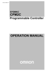
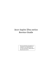
Aspire G7700 Tour
This section is a virtual tour of the Aspire G7700 system’s interior and exterior components.
Closed Front Panel
4
Item
Component
1
Hinge screws x4
2
Door hinges x4
3
Bezel door
Chapter 1
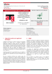
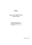
Front Panel
Item
Icon
Component
1
USB 2.0 ports
2
Headphone/line-out jack
3
Microphone/speaker-out/line-in jack
4
Power button/power indicator
5
Optical disk drives
6
XD (eXtreme Digital) slot
7
USB 2.0 port
8
IEEE 1394 port (4-pin)
9
CFI/II (CompactFlash Type I/II) slot
10
Drive bay door
11
Easy-swap hard disk drives (1-4)
12
MS/MS Pro (Memory Stick/Memory Stick Pro Duo) slot
13
SD/MMC (SecureDigital/MultimediaCard) slot
14
Optical disk drive eject buttons
Chapter 1
5
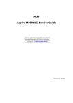
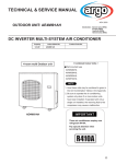
Rear Panel
Item
6
Icon
Component
1
Power supply
2
PS2 mouse port
3
System fan
4
Network ports
5
Rear speaker jack
6
Center speaker/subwoofer jack
7
Expansion slot locks
8
S-video port
9
DVI port
10
Audio-in/line-in jack
11
Headphone/line-out/front speaker jack
12
Microphone/line-in jack
13
Side speaker/line-out jack
14
USB 2.0 ports
15
CL_CMOS
CMOS (Complementary Metal Oxide Semiconductor) reset button
16
ESATA
eSATA (External Serial Advanced Technology Attachment) ports
17
S/PDIF
S/PDIF port
18
IEEE 1394 port (6-pin)
19
PS2 keyboard port
20
Power connector
21
Main power switch
Chapter 1
Internal Components
Chapter 1
Item
Component
1
Liquid cooling system
2
Mainboard
3
System memory
4
Release sliders for optical drives
5
Hard drive backplane board
6
Release sliders for HDD drives
7
Expansion slot lock levers
8
Expansion card
9
System fan
10
Power supply module
7
System LED Indicators
This section describes the different system LED indicators.
LED indicator
Color
LED status
Description
Power
Blue
On
The system has AC power and is powered on.
Blinking
The system is in standby mode.
Green
Blinking
Ongoing HDD activity.
Amber
On
HDD failure
Green/
Amber
Flashing
HDD is rebuilding.
LAN port
network activity
LED
(left)
Orange
On (steady state)
Active network link
Blinking (brighter
and pulsing)
Ongoing network data activity
Off
Off-line network
LAN port
network link
LED (right)
Orange
On
1000 Mbps link network access
Green
On
100 Mbps link network access
Off
10 Mbps link network access
HDD activity
8
Chapter 1
Mainboard LED indicators
The mainboard LED indicators are easy to check the system status when user open the cover or testing the system
board.
Chapter 1
LED status
Description
PCIE1 (blue)
Lights when PCI E1 slot is functional.
PCIE2 (blue)
Lights when PCI E2 slot is functional.
PCIE3 (blue)
Lights when PCI E3 slot is functional.
PCIE4 (blue)
Lights when PCI E4 slot is functional.
PCI (blue)
Lights when PCI1 slot is functional.
PCIE5 (blue)
Lights when PCI E5 slot is functional.
PCIE6 (blue)
Lights when PCI E6 slot is functional.
DIMM1 (orange)
Lights when the DIMM1 slot is functional.
DIMM2 (green)
Lights when the DIMM2 slot is functional.
DIMM3 (green)
Lights when the DIMM3 slot is functional.
DIMM4 (orange)
Lights when the DIMM4 slot is functional.
HDD (pink)
Lights when the HDD is functional.
Power (blue)
Lights when the system is powered on.
Standby (pink)
Lights when the system is in standby mode.
9
10
Chapter 1
Chapter 2
System Utilities
CMOS Setup Utility
CMOS setup is a hardware configuration program built into the system ROM, called the complementary metaloxide semiconductor (CMOS) Setup Utility. Since most systems are already properly configured and
optimized, there is no need to run this utility. You will need to run this utility under the following conditions.
When changing the system configuration settings
When redefining the communication ports to prevent any conflicts
When modifying the power management configuration
When changing the password or making other changes to the security setup
When a configuration error is detected by the system and you are prompted ("Run Setup"
message) to make changes to the CMOS setup
NOTE: If you repeatedly receive Run Setup messages, the battery may be bad. In this case, the system
cannot retain configuration values in CMOS. Ask a qualified technician for assistance.
CMOS setup loads the configuration values in a battery-backed nonvolatile memory called CMOS RAM. This
memory area is not part of the system RAM which allows configuration data to be retained when power is
turned off.
Before you run the CMOS Setup Utility, make sure that you have saved all open files. The system reboots
immediately after you close the Setup.
NOTE: CMOS Setup Utility will be simply referred to as “BIOS”, "Setup", or "Setup utility" in this guide.
The screenshots used in this guide display default system values. These values may not be the same
those found in your system.
Chapter 2
11
Entering CMOS setup
1.
Turn on the server and the monitor.
If the server is already turned on, close all open applications, then restart the server.
2.
During POST, press Delete.
If you fail to press Delete before POST is completed, you will need to restart the server.
The Setup Main menu will be displayed showing the Setup’s menu bar. Use the left and right arrow keys
to move between selections on the menu bar.
Navigating Through the Setup Utility
Use the following keys to move around the Setup utility.
Left and Right arrow keys – Move between selections on the menu bar.
Up and Down arrow keys – Move the cursor to the field you want.
PgUp and PgDn keys – Move the cursor to the previous and next page of a multiple page menu.
Home – Move the cursor to the first page of a multiple page menu.
End – Move the cursor to the last page of a multiple page menu.
+ and - keys – Select a value for the currently selected field (only if it is user-configurable). Press
these keys repeatedly to display each possible entry, or the Enter key to choose from a pop-up
menu.
NOTE: Grayed-out fields are not user-configurable.
Enter key – Display a submenu screen.
NOTE: Availability of submenu screen is indicated by a (>).
12
Esc – If you press this key:
On one of the primary menu screens, the Exit menu displays.
On a submenu screen, the previous screen displays.
When you are making selections from a pop-up menu, closes the pop-up without making a
selection.
F1 – Display the General Help panel.
F6 – Press to load optimized default system values.
F7 – Press to load fail-safe default system values.
F10 – Save changes made the Setup and close the utility.
Chapter 2
Setup Utility Menus
The tabs on the Setup menu bar correspond to the six primary CMOS Setup menus, namely:
Product Information
Standard CMOS Features
Advanced BIOS Features
Advanced Chipset Features
Integrated Peripherals
Power Management Setup
PC Health Status
Frequency/Voltage Control
BIOS Security Features
Load Optimized Defaults
Save & Exit Setup
Exit Without Saving
In the descriptive table following each of the menu screenshots, settings in boldface are the default and
suggested settings.
Chapter 2
13
Product Information
Select the Product Information from the CMOS Setup menu, then press Enter. The basic information about the
system appears on the screen. These entries are for your reference only and are not user-configurable.
14
Chapter 2
Standard CMOS Features
Parameter
Description
System Date
Set the date following the weekday-month-day-year format.
Option
System Time
Set the system time following the hour-minute-second format.
Primary Master/Slave
& Serial-ATA 1~6
channel & E-SATA 1/2
Press Enter to view detailed device information connected to the IDE/SATA/E-SATA connectors.
Halt On
Determines whether the system will stop for an error during the POST.
All, But KB
No Errors
All Errors
Primary IDE Master/Primary IDE Slave/SATA port/E-SATA
Parameter
Description
Option
Type
Selects the type of device connected to the system.
Auto
Not Installed
CD/DVD
ARMD
LBA/Large Mode
Selects the hard disk drive translation method. For drivers with more than 504
MB, LBA mode is necessary.
Auto
Block Mode
When set to Auto, the data transfer from and to the device occurs multiple
sectors at a time if the device supports it.
Auto
Disabled
Disabled
When set to Disable, the data transfer from and to the device occurs one sector
at a time.
PIO Mode
Set the PIO (Programmed Input/Output) mode for the IDE/SATA/E-SATA drive.
DMA Mode
Select a DMA (Direct Memory Access) transfer mode to enhance hard disk
performance.
Auto
0, 1, 2, 3, 4
Auto
SWDMAn
MWDMAn
UDMAn
S.M.A.R.T. (Hard Disk
S.M.A.R.T)
Enables or disables the Self Monitoring Analysis And Reporting Technology
(S.M.A.R.T.) capability of the hard disks. S.M.A.R.T. is a utility that monitors the
hard disk’s condition.
Auto
32Bit Data Transfer
Enables or disables the 32-bit data transfer mode.
Enabled
Enabled
Disabled
Disabled
Chapter 2
15
Advanced BIOS Features
Parameter
Description
Option
Reset Configuration Data
Allows you to manually force BIOS to clear the previously saved Extended
System Configuration Data (ESCD) data and reconfigure the settings.
No
Yes
When set to no, it lets the BIOS configure all the devices in the system.
When set to yes, it lets the OS configure Plug and Play (PnP) devices not
required for boot if the system has a PnP OS.
Quick Boot
Allows you to decrease the time it takes to boot the computer by shortening
or skipping certain standard booting process.
Enabled
Quiet Boot
When enabled, the BIOS splash screen displays during startup.
Enabled
When disabled, the diagnostic screen displays during startup.
Disabled
Specifies the boot order from the available devices.
Hard Disk
1st/2nd/3rd/4th Boot Device
Disabled
CD^DVD
Removable
Device
LAN
Hard Disk Drive Priority
Press Enter to access the Hard Disk Drive Priority submenu and specify the boot device
priority sequence from available hard drives.
Optical Disk Drive Priority
Press Enter to access the Optical Disk Drive Priority submenu and specify the boot device
priority sequence from available CD/DVD drives.
Removable Device Priority
Press Enter to access the Removable Device Priority submenu and specify the boot device
priority sequence from available removable drives.
Bootup Num-Lock
Selects power on state for Num Lock.
Boot Sector Virus Protection
Enables or disables the boot sector virus protection feature. If enabled,
BIOS will show a warning message on the screen or an alarm beep when
someone attempts to write data into this area.
Disabled
Hard Disk Write Protect
Enables or disables the hard disk write protect feature.
Disabled
USB Beep Message
Enables or disables BIOS to display error beeps or messages during USB
device enumeration.
On
Off
Enabled
Enabled
16
Disabled
Enabled
Chapter 2
Advanced Chipset Features
Parameter
Description
Option
Intel EIST
Enables or disables the processor speed to be controlled by the OS.
Enabled
Disabled
Intel XD Bit
If disabled, it forces the Execute Disable (XD) Bit feature flag to always
return to 0.
Enabled
Intel VT
Enabled or disables the Virtualization Technology (VT) availability.
Enabled
Disabled
Disabled
Chapter 2
17
Integrated Peripherals
Parameter
Description
Option
Onboard IDE Controller
Enables or disables the onboard IDE controller.
Enabled
Disabled
Onboard SATA Controller
Enables or disables the onboard SATA controller.
Onboard SATA Mode
Select an operating mode for the onboard SATA.
Enabled
Disabled
RAID
Native IDE
SATA 1 to 6
Enables or disables the SATA RAID on ports 1 to 6.
Disabled
Note: This parameter is configurable only if the SATA Mode is set to
RAID.
Enabled
ESATA RAID/IDE Controller
Enables or disables the ESATA RAID/IDE controller.
Disabled
ESATA RAID Mode
Select a operating mode for the ATA controller.
Enabled
IDE
RAID
Onboard USB Controller
Enables or disables the onboard USB controller.
Legacy USB Support
Enables or disables support for legacy USB devices.
Enabled
Disabled
Enabled
Disabled
Onboard Audio Controller
Enables or disables the onboard audio controller.
Onboard LAN1/2 Controller
Enables or disables the onboard LAN 1 or 2 controller.
Enabled
Disabled
Enabled
Disabled
Onboard LAN1/2 Option
ROM
Enables or disables the load of embedded option ROM for onboard
network controller.
Disabled
Onboard 1394 Controller
Enables or disables the onboard IEEE 1394 controller.
Enabled
Enabled
Disabled
18
Chapter 2
Power Management Setup
Parameter
Description
Option
ACPI Aware O/S
Enables or disables the Advanced Configuration and Power
Management (ACPI) function.
Enabled
ACPI Suspend Mode
Select an ACPI state.
S3 (STR)
Power On by RTC Alarm
Enables or disables to boot the system on scheduled date/time.
Disabled
S1 (POS)
Disabled
Enabled
Power On by PCIE Devices
Enables or disables to wake up the system from a power saving mode
through an event on PCI Express device.
Enabled
Power On by PCI Devices
Enables or disables to wake up the system from a power saving mode
through a Power Management Event (PME).
Enabled
Wake Up by PS/2 Keyboard
Enables or disables to wake up the system from a power saving mode
using a PS2 keyboard.
Enabled
Wake Up by PS/2 Mouse
Enables or disables to wake up the system from a power saving mode
using a PS2 mouse.
Enabled
Wake Up by USB Keyboard/
Mouse
If enabled, press any key or click the mouse will wake system from S1/
S3 state.
Enabled
Restore On AC Power Loss
Enables or disables the system to reboot after a power failure or
interrupt occurs.
Off
Disabled
Disabled
Disabled
Disabled
Disabled
On
Last State
Chapter 2
19
PC Health Status
Parameter
Description
Option
CPU Warning Temperature
Sets the warning threshold for processor temperature. When processor
temperature exceeds the threshold, BIOS will emit warning sound.
Disabled
60 C/140 F
65 C/149 F
70 C/158 F
CPU Shutdown Temperature
Sets the processor shutdown temperature.
Disabled
700 C/158 F
75 C/167 F
80 C/176 F
CPU Fan Smart Fan
Enables or disables the processor fan speed control function.
System Fan1 Smart Fan
Enables or disables the system fan 1 speed control function.
Enabled
Disabled
Enabled
Disabled
20
Chapter 2
Frequency Control
Parameter
Description
Option
D.O.T. Control
Enables or disables Dynamic Overclocking Technology (D.O.T.). DOT
detects the load balance of the processor while running programs, and to
adjust the best processor frequency automatically. When the system
detects the CPU is running programs, it will speed up the processor
automatically to make the program run smoothly and faster. When the
CPU is temporarily suspending or staying in the low load balance, it will
restore the default settings instead.
Disabled
Options include:
Commander
SLI-Ready Memory
•
Disabled - DOT is disabled
•
Private - First level of overclocking, increases the frequency by 1%
•
Sergeant - Second level of overclocking, increases the frequency by 3%
•
Captain - Third level of overclocking, increases the frequency by 5%
•
Colonel - Fourth level of overclocking, increases the frequency by 7%
•
General - Fifth level of overclocking, increases the frequency by 10%
•
Commander - Sixth level of overclocking, increases the frequency by
15%
Select the Serial Presence Detect (SPD) profile for SLI-Ready memory
modules.
Private
Sergeant
Captain
Colonel
General
Disabled
0% CPU OC
1% CPU OC
2% CPU OC
3% CPU OC
4% CPU OC
5% CPU OC
Max CPU OC
Expert
System Clock Mode
When set to Manual, allow you to configure the FSB and memory clock
frequency.
Auto
Linked
Manual
FCB Clock (MHz)
Sets the FSB frequency depend on CPU ranged from 400 to 2500 MHz.
Any value that is not within this range will have no effect.
400-2500 MHz
Memory Clock (MHz)
Sets the memory frequency ranged from 400 to 1400 MHz. Any value that
is not within this range will have no effect.
400-1400 MHz
Adjust CPU Ratio
Sets the processor ratio. Available only when the processor supports this
function.
9
6
7
8
Chapter 2
21
Parameter
Description
Option
Adjust DRAM Configuration
Press Enter to access the Adjust DRAM Configuration submenu to override the memory’s
Serial Presence Detect (SPD) settings by manually entering values for DRAM timings.
Adjust PCI-E Frequency
Sets the PCI Express clock frequency.
101 to 115
MCP PCI-Express
Frequency, MHz
Sets the reference clock for the media and communications processor
(MCP) PCI Express
101 to 115
Auto Disabled DIMM/PCI
Frequency
Enables or disables the system to remove (turn off) clocks from empty
DIMM and PCI slots to minimize electromagnetic interference (EMI).
Enabled
CPU Voltage (V)
Select processor voltage control.
Auto
DRAM Voltage (V)
Select memory voltage control to increase memory speed.
2.00
Disabled
Min: 1.80v
Max: 2.80 V
NB Voltage (V)
Select Northbridge (NB) chipset voltage control.
Auto
Min: 1.200v
Max: 1.600 V
SB Voltage (V)
Select Southbridge (SB) chipset voltage control.
Auto
Min: 1.500v
Max: 2.000 V
NB Memory Reference
Voltage
Set the NB memory reference voltage.
Auto
DIMM Memory Reference
Voltage
Set the memory reference voltage.
Auto
Memory Terminator Voltage
Set the memory terminator voltage.
Auto
CPU GTL Reference
Voltage
Set the processor Gunning Transreceiver Logic (GTL) reference voltage to
provide headroom for overclocking quad-core processors.
Auto
NB GTL Reference Voltage
Set the NB GTL reference voltage to provide the best level of stability on
the system.
Auto
FSB Terminator Voltage
Set the FSB terminator voltage.
Auto
Spread Spectrum
Enables or disables the reduction of the mainboard’s EMI.
Enabled
Note: Remember to disable the Spread Spectrum feature if you are
overclocking. A slight jitter can introduce a temporary boost in clock speed
causing the overclocked processor to lock up.
Disabled
22
Chapter 2
BIOS Security Features
The BIOS Security menu allows you to safeguard and protect the system from unauthorized use by setting up
access passwords.
Parameter
Description
Supervisor Password
Indicates the status of the supervisor password.
Option
User Password
Indicates the status of the user password.
Change Supervisor
Password
Supervisor password prevents unauthorized access to the BIOS Setup Utility.
Set User Password
User password is used to control entry access to the BIOS Setup Utility. User password is
available only when a Supervisor password is set.
Press Enter to change the Supervisor password.
Press Enter to change the User password.
Setting a supervisor password
1.
Use the up/down arrow keys to select Change Supervisor Password menu then press Enter.
A password box will appear.
2.
Type a password then press Enter.
The password may consist up to six alphanumeric characters (A-Z, a-z, 0-9)
3.
Retype the password to verify the first entry then press Enter again.
4.
Press F10.
5.
Select Yes to save the new password and close the Setup Utility.
Changing the supervisor password
1.
Use the up/down arrow keys to select Change Supervisor Password menu then press Enter.
2.
Type the original password then press Enter.
3.
Type a new password then press Enter.
4.
Retype the password to verify the first entry then press Enter again.
5.
Press F10.
6.
Select Yes to save the new password and close the Setup Utility.
Chapter 2
23
Removing a supervisor password
1.
Use the up/down arrow keys to select Change Supervisor Password menu then press Enter.
2.
Enter the current password then press Enter.
3.
Press Enter twice without entering anything in the password fields.
Setting a user password
1.
Use the up/down arrow keys to select Set User Password menu then press Enter.
A password box will appear.
2.
Type a password then press Enter.
The password may consist up to six alphanumeric characters (A-Z, a-z, 0-9)
3.
Retype the password to verify the first entry then press Enter again.
4.
Press F10.
5.
Select Yes to save the new password and close the Setup Utility.
Changing the user password
1.
Use the up/down arrow keys to select Set User Password menu then press Enter.
2.
Type the original password then press Enter.
3.
Type a new password then press Enter.
4.
Retype the password to verify the first entry then press Enter again.
5.
Press F10.
6.
Select Yes to save the new password and close the Setup Utility.
Removing a user password
24
1.
Use the up/down arrow keys to select Set User Password menu then press Enter.
2.
Enter the current password then press Enter.
3.
Press Enter twice without entering anything in the password fields.
Chapter 2
Load Optimized Defaults
The Load Optimized Defaults menu allows you to load the default settings for all BIOS setup parameters.
Setup defaults are quite demanding in terms of resources consumption. If you are using low-speed memory
chips or other kinds of low-performance components and you choose to load these settings, the system might
not function properly.
Chapter 2
25
Save & Exit Setup
The Save & Exit Setup menu allows you to save changes made and close the Setup Utility.
26
Chapter 2
Exit Without Saving
The Exit Without Saving menu allows you to discard changes made and close the Setup Utility.
Chapter 2
27
28
Chapter 2
Chapter 3
System Disassembly
This chapter contains step-by-step procedures on how to disassemble the desktop computer for maintenance
and troubleshooting.
Disassembly Requirements
To disassemble the computer, you need the following tools:
Wrist grounding strap and conductive mat for preventing electrostatic discharge
Flat-blade screwdriver
Philips screwdriver
Hex screwdriver
Plastic flat-blade screwdriver
Plastic tweezers
NOTE: The screws for the different components vary in size. During the disassembly process, group the
screws with the corresponding components to avoid mismatch when putting back the components.
Chapter 3
29
Pre-disassembly Procedure
Before proceeding with the disassembly procedure, perform the steps listed below:
30
1.
Turn off the system and all the peripherals connected to it.
2.
Unplug the power cord from the power outlets.
3.
Unplug the power cord from the system.
4.
Unplug all peripheral cables from the system.
5.
Place the system unit on a flat, stable surface.
Chapter 3
Main Unit Disassembly
External Modules Disassembly Flowchart
The flowchart below gives you a graphic representation on the entire disassembly sequence and instructs you
on the components that need to be removed during servicing.
MAIN UNIT DISASSEMBLY
MAIN UNIT
LEFT AND RIGHT HINGES
BEZEL DOOR
LEFT AND RIGHT
SIDE PANEL
FRONT BEZEL
OPTICAL DISK DRIVE
VIDEO CARDS
PCI CARDS
TV TUNER CARD
Bx2
Cx2
CARD READER BOARD
CARD READER DRIVE
Ax4
HDD MODULE
HDD CAGE
HDD
Dx2
BACKPLANE
BOARD
MEMORY MODULES
Ex4
LIQUID COOLER
LIQUID COOLER FAN
ASSEMBLY
Fx4
FAN
CPU
Gx4
POWER SUPPLY
Hx4
HDD FAN
TOP COVER
Ix2
USB BOARD
Jx6
MAINBOARD
FRONT AND REAR
FOOT STANDS
Chapter 3
31
Screw List
32
Screw
Part No.
A
HDD carrier screw
86.1AQ36.450
B
Card reader carrier screw
N/A
C
Card reader board screw
N/A
D
M#6-32 L4.6 BZN
86.00J11.A60
E
Liquid cooler screw
86.00J61.767
F
Liquid cooler fan screw
N/A
G
M HEX #6-32 L5 BZN
86.00J59.A60
H
M#6-32 L4.6 BZN
86.00J10.A60
I
M #6-32 L5 BZN
86.00E66.D60
J
MA HEX #6-32 5MM NI
86.2G5B6.013
Chapter 3
Removing the Bezel Door
1.
Perform the pre-disassembly procedure described on page 30.
2.
Grasp the front edge of the bezel door, then tilt up until it is aligned with the top panel.
3.
Remove the four screws that hold the door hinges to the right side panel (1).
4.
Remove the four screws that hold the door hinges to the left side panel (2).
5.
Detach the bezel door with hinges from the system (3).
Chapter 3
33
Removing the Hard Disk Drive
34
1.
Remove the bezel door. Refer to the previous section for instructions.
2.
Open the drive bay door.
3.
Press the HDD carrier latch, then pull the lever down to the fully open position.
Chapter 3
4.
Pull the carrier out of the drive bay.
5.
Place the HDD carrier on a clean, static-free network surface.
6.
If you are replacing a hard disk, remove the four screws (A) that secure the hard disk to the carrier.
Screw (Quantity)
Color
Torque
Part No.
HDD carrier screw (4)
Silver
3.5 to 4.5 kgf-cm
N/A
7.
Remove the disk from the carrier.
8.
Keep the screws for later installation.
Chapter 3
35
Removing the Left Side Panel
36
1.
See “Removing the Bezel Door” on page 33.
2.
Release the two panel locks on the rear of the left side panel.
3.
Hold the rear edge of the panel and slide the panel towards the rear (1), slightly raise the panel then lift the
panel away from the chassis (2).
Chapter 3
Removing the Right Side Panel
1.
See “Removing the Bezel Door” on page 33.
2.
Pull the top edge out and slightly lift up to detach the tabs inside the panel (1), then slide the panel
towards the rear of the chassis (2).
Chapter 3
37
Removing the Front Bezel
38
1.
See “Removing the Bezel Door” on page 33.
2.
See “Removing the Left Side Panel” on page 36.
3.
Disconnect the front panel cable from the mainboard.
4.
Release the front bezel retention tabs from the chassis interior.
Chapter 3
5.
Pull the bezel away from the chassis.
Chapter 3
39
Removing the Optical Drive
40
1.
See “Removing the Bezel Door” on page 33.
2.
See “Removing the Left Side Panel” on page 36.
3.
See “Removing the Front Bezel” on page 38.
4.
Disconnect the power and data cables from rear of the old drive.
5.
Move the release slider of the selected drive to the unlock position, then pull the drive out of the device
bay.
Chapter 3
Removing the Video Cards
1.
See “Removing the Bezel Door” on page 33.
2.
See “Removing the Left Side Panel” on page 36.
3.
Lay the system on its side (with components showing).
4.
Remove the SLI bridge cable from the video cards, then press down on the expansion slot release latch.
5.
Gently pull the card to detach it from the mainboard.
6.
Do the same to the other card.
Chapter 3
41
7.
42
Disconnect the power cables from the video cards, then remove the cards.
Chapter 3
Removing the TV Tuner Card
1.
See “Removing the Bezel Door” on page 33.
2.
See “Removing the Left Side Panel” on page 36.
3.
See “Removing the Video Cards” on page 41.
4.
Press down on the expansion slot release latch.
5.
Gently pull the card to detach it from the mainboard.
Chapter 3
43
Removing the Card Reader Drive
44
1.
See “Removing the Bezel Door” on page 33.
2.
See “Removing the Left Side Panel” on page 36.
3.
See “Removing the Front Bezel” on page 38.
4.
Release cables from the retention clip.
5.
Disconnect the USB and 1394 cables from the mainboard.
Chapter 3
6.
Move the release slider to the unlock position and push the module into the bay, then remove it from the
chassis.
Chapter 3
45
Removing the Card Reader Board
1.
See “Removing the Bezel Door” on page 33.
2.
See “Removing the Left Side Panel” on page 36.
3.
See “Removing the Front Bezel” on page 38.
4.
See “Removing the Card Reader Drive” on page 44.
5.
Place the module on a clean, static-free surface.
6.
Remove the two screws (B) that secure the cover to the carrier.
Screw (Quantity)
Color
Torque
Part No.
Card reader carrier screw (2)
Silver
N/A
N/A
7.
46
Disconnect the USB cable from the card reader board.
Chapter 3
8.
Remove the card reader carrier cover.
9.
Remove the two screws (C) that secure the card reader board to the carrier.
Screw (Quantity)
Color
Torque
Part No.
Card reader board screw (2)
Silver
N/A
N/A
10. Remove the card reader board from the carrier.
Chapter 3
47
Removing the Backplane Board
48
1.
See “Removing the Bezel Door” on page 33.
2.
See “Removing the Hard Disk Drive” on page 34.
3.
See “Removing the Left Side Panel” on page 36.
4.
See “Removing the Front Bezel” on page 38.
5.
See “Removing the Video Cards” on page 41.
6.
Slide the HDD cage slider up, then pull the cage out of the drive bay.
7.
Remove the two screws (D) from the backplane board.
Screw (Quantity)
Color
Torque
Part No.
M#6-32 L4.6 BZN (2)
Silver
3.5 to 4.5 kgf-cm
86.00J11.A60
Chapter 3
8.
Slide the backplane board forward (1) then remove the board from the HDD cage (2).
Chapter 3
49
Removing the Memory Modules
IMPORTANT:Before removing any DIMM from the memory board, make sure to create a backup file of all
important data.
50
1.
See “Removing the Bezel Door” on page 33.
2.
See “Removing the Left Side Panel” on page 36.
3.
Press the holding clips on both sides of the DIMM slot outward to release the DIMM.
4.
Gently pull the DIMM upward and to pull it away from the mainboard.
Chapter 3
Removing the Liquid Cooler Fan Assembly
WARNING:The heat sink becomes very hot when the system is on. NEVER touch the heat sink with any metal
or with your hands.
1.
See “Removing the Bezel Door” on page 33.
2.
See “Removing the Left Side Panel” on page 36.
3.
See “Removing the Front Bezel” on page 38.
4.
Disconnect the power and two fan cables.
5.
Loosen the four screws on the liquid cooler, in the order shown.
Chapter 3
51
6.
52
Remove the four screws (E) securing the fan end of the liquid cooler fan assembly to the chassis.
Screw (Quantity)
Color
Torque
Part No.
Liquid cooler screw (4)
Black
4.5 to 5.5 kgf-cm
N/A
7.
Lift the fan and heat exchanger end of the liquid cooler assembly from the chassis, then gently detach the
cooler end from the mainboard.
8.
Lay cooler on its side—with the thermal patch facing sideways. Do not let the thermal patch touch the
work surface.
9.
Use an alcohol pad to wipe off the thermal grease from both the liquid cooler and the processor.
Chapter 3
Removing the Fan from the Liquid Cooler
1.
See “Removing the Bezel Door” on page 33.
2.
See “Removing the Left Side Panel” on page 36.
3.
See “Removing the Liquid Cooler Fan Assembly” on page 51.
4.
Remove the four screws (F) that secure the fan to the heat exchanger on the liquid cooler fan assembly
and store screws and washer for later use, then detach the fan from the cooler.
Screw (Quantity)
Color
Torque
Part No.
Liquid cooler fan screw (4)
Silver
4.5 to 5.5 kgf-cm
N/A
Chapter 3
53
Removing the Processor
IMPORTANT:Before removing a processor from the mainboard, make sure to create a backup file of all
important data.
WARNING:The processor becomes very hot when the system is on. Allow it to cool off first before handling.
54
1.
See “Removing the Bezel Door” on page 33.
2.
See “Removing the Left Side Panel” on page 36.
3.
See “Removing the Memory Modules” on page 50.
4.
See “Removing the Liquid Cooler Fan Assembly” on page 51.
5.
Press down to release load lever.
6.
Lift the load lever up and open the load plate.
Chapter 3
7.
Grasp the processor by its edges and lift it out of its socket.
IMPORTANT:If you are going to install a new processor, note the arrow on the corner to make sure the
processor is properly oriented over the socket.
Chapter 3
55
Removing the Power Supply
1.
See “Removing the Bezel Door” on page 33.
2.
See “Removing the Left Side Panel” on page 36.
3.
See “Removing the Front Bezel” on page 38.
4.
See “Removing the Optical Drive” on page 40.
5.
See “Removing the Video Cards” on page 41.
6.
See “Removing the TV Tuner Card” on page 43.
7.
See “Removing the Card Reader Drive” on page 44.
8.
See “Removing the Backplane Board” on page 48.
9.
See “Removing the Memory Modules” on page 50.
10. See “Removing the Liquid Cooler Fan Assembly” on page 51.
11. See “Removing the Processor” on page 54.
12. Release the cables from the retaining clips.
13. Disconnect the power supply cables from the mainboard.
56
Chapter 3
14. Remove the four screws (G) that secure the power supply to the chassis.
Screw (Quantity)
Color
Torque
Part No.
M Hex #6-32 L5 BZN (4)
Black
5.5 to 6.5 kgf-cm
86.00J59.A60
15. Lift the power supply module out of the chassis.
Chapter 3
57
Removing the HDD Fan
1.
See “Removing the Bezel Door” on page 33.
2.
See “Removing the Left Side Panel” on page 36.
3.
See “Removing the Front Bezel” on page 38.
4.
See “Removing the Card Reader Drive” on page 44.
5.
Disconnect the fan cable from the mainboard.
6.
Remove the four screws (H) that secure the fan to the chassis.
7.
58
Screw (Quantity)
Color
Torque
Part No.
M#6-32 L20 BZN (4)
Black
N/A
86.00J10.A60
Remove the fan from the chassis.
Chapter 3
Removing the Top Cover
1.
See “Removing the Bezel Door” on page 33.
2.
See “Removing the Left Side Panel” on page 36.
3.
See “Removing the Front Bezel” on page 38.
4.
See “Removing the Optical Drive” on page 40.
5.
See “Removing the Video Cards” on page 41.
6.
See “Removing the TV Tuner Card” on page 43.
7.
See “Removing the Card Reader Drive” on page 44.
8.
See “Removing the Backplane Board” on page 48.
9.
See “Removing the Memory Modules” on page 50.
10. See “Removing the Liquid Cooler Fan Assembly” on page 51.
11. See “Removing the Processor” on page 54.
12. See “Removing the Power Supply” on page 56.
13. Press the top cover tabs to disengage with the slots on the chassis.
14. Remove the top cover.
Chapter 3
59
Removing the USB Board
1.
See “Removing the Bezel Door” on page 33.
2.
See “Removing the Optical Drive” on page 40.
3.
See “Removing the Video Cards” on page 41.
4.
See “Removing the TV Tuner Card” on page 43.
5.
See “Removing the Card Reader Drive” on page 44.
6.
See “Removing the Backplane Board” on page 48.
7.
See “Removing the Memory Modules” on page 50.
8.
See “Removing the Liquid Cooler Fan Assembly” on page 51.
9.
See “Removing the Processor” on page 54.
10. See “Removing the Power Supply” on page 56.
11. See “Removing the Top Cover” on page 59.
12. Detach the USB and audio cables from the mainboard.
13. Slide and lift the front I/O bracket.
60
Chapter 3
14. Turn it over then detach the cables from the USB board.
15. Remove the two screws (I) that secure the board to the bracket.
Screw (Quantity)
Color
Torque
Part No.
M #6-32 L5 BZN (2)
Black
N/A
86.00E66.D60
16. Remove the USB board.
Chapter 3
61
Removing the Mainboard
1.
See “Removing the Bezel Door” on page 33.
2.
See “Removing the Optical Drive” on page 40.
3.
See “Removing the Video Cards” on page 41.
4.
See “Removing the TV Tuner Card” on page 43.
5.
See “Removing the Card Reader Drive” on page 44.
6.
See “Removing the Backplane Board” on page 48.
7.
See “Removing the Memory Modules” on page 50.
8.
See “Removing the Liquid Cooler Fan Assembly” on page 51.
9.
See “Removing the Processor” on page 54.
10. See “Removing the Power Supply” on page 56.
11. See “Removing the HDD Fan” on page 58.
12. See “Removing the Top Cover” on page 59.
13. See “Removing the USB Board” on page 60.
14. Disconnect the LED cable from the mainboard.
62
Chapter 3
15. Remove the nine screws (J) that secure the mainboard to the chassis, in the order shown.
Screw (Quantity)
Color
Torque
Part No.
HEX #6-32 5MM NI (6)
Silver
4.5 to 5.5 kgf-cm
86.2G5B6.013
16. Lift the board from the chassis.
Chapter 3
63
Removing the Front Foot Stand
64
1.
See “Removing the Bezel Door” on page 33.
2.
See “Removing the Left Side Panel” on page 36.
3.
Lay the system on its side (with components showing).
4.
Press the tabs on the front foot stand to disengage with the slots on the chassis.
5.
Remove the foot stand.
Chapter 3
Removing the Rear Foot Stand
1.
See “Removing the Bezel Door” on page 33.
2.
See “Removing the Left Side Panel” on page 36.
3.
Lay the system on its side (with components showing).
4.
Press the tabs on the rear foot stand to disengage with the slots on the chassis.
5.
Remove the foot stand.
Chapter 3
65
66
Chapter 3
Chapter 4
System Troubleshooting
This chapter provides instructions on how to troubleshoot system hardware problems.
Hardware Diagnostic Procedure
IMPORTANT:The diagnostic tests described in this chapter are only intended to test Acer products. Non-Acer
products, prototype cards, or modified options can give false errors and invalid system response.
1.
Obtain the failing symptoms in as much detail as possible.
2.
Verify the symptoms by attempting to recreate the failure by running the diagnostic tests or repeating the
same operation.
3.
Refer to the table below to determine which corrective action to perform.
Problem
Symptom
Section to Refer to
Power failure
The power indicator does not light up
or stay lit.
“Power System Check” on page 68
POST failure
POST does not complete. No beep
or error codes issued.
“POST Error and Beep Codes” on page 69.
POST detects an error and displayed
messages on screen.
Chapter 4
67
System Check Procedures
Power System Check
If the system will power on, skip this section. Refer to System External Inspection.
If the system will not power on, check if the power cable is properly connected to the system and AC source.
System External Inspection
1.
Inspect the LED indicators on the front panel, which can indicate the malfunction. For the LED locations
and description of their behavior, see “System LED Indicators” on page 6.
2.
Make sure that air flow is not blocked.
3.
Make sure nothing in the system is making contact that could short out power.
4.
If the problem is not evident, continue with System Internal Inspection.
System Internal Inspection
1.
Turn off the system and all the peripherals connected to it.
2.
Make sure the main power switch is set to the 0 position.
3.
Unplug the power cord from the power outlets.
4.
Unplug the power cord from the system.
5.
Unplug all peripheral cables from the system.
6.
Place the system unit on a flat, stable surface.
7.
Remove the system covers. For instructions on removing system covers, refer to “System Disassembly”
on page 29.
8.
Verify that components are properly seated.
9.
Verify that all cable connectors inside the system are firmly and correctly attached to their appropriate
connectors.
10. Verify that all components are Acer-qualified and supported.
11. Replace the system covers.
12. Power on the system.
13. If the problem with the system is not evident, you can try viewing the POST messages and BIOS event
logs during the system startup.
68
Chapter 4
POST Error and Beep Codes
NOTE: Perform the FRU replacement or actions in the sequence shown in FRU/Action column, if the FRU
replacement does not solve the problem, put the original part back in the computer. Do not replace a
non-defective FRU.
The error messages in the following table indicate the BIOS signals on the screen and the error symptoms
classified by functions. If the symptom is not included on the list, please refer to “Undetermined Problems”.
NOTE: Most of the error messages occur during POST. Some of them display information about a hardware
device, e.g., the amount of memory installed. Others may indicate a problem with a device, such as the
way it has been configured.
NOTE: If the system fails after you make changes in the BIOS Setup Utility menus, reset the computer, enter
Setup and install Setup defaults or correct the error.
POST Code (Hex)
POST Routine Description
FFh
Turn On LPC Positive Decode
Init At Start POST_FAR
03h
Init At Start POST_FAR
FFh
Allocate EBDA_FAR
Init At Start POST_FAR
03h
Cp Init At Start POST_FAR
Init At Start POST_FAR
03h
NB_Init At Start POST_FAR
Cp Init At Start POST_FAR
03h
SB_Init At Start POST_FAR
Cp Init At Start POST_FAR
FFh
SB PCIE_Init At Start POST_FAR
SB_Init At Start POST_FAR
03h
OEM_Init At Start POST_FAR
Cp Init At Start POST_FAR
FFh
OEM BOARD_A_Cp Init At Start POST_FAR
Cp Init At Start POST_FAR
04h
Init CMOS_FAR
FFh
Init CMOS Based Data_FAR
Init CMOS_FAR
FFh
Disable Smithfield TM2_FAR
Init CMOS_FAR
FFh
Init PIC 8259_FAR
Init INT System_FAR
05h
Init INT System_FAR
06h
Init Timer 8254_FAR
Init INT System_FAR
FFh
Install POST INT 1Ch Handler_FAR
Init Timer 8254_FAR
FFh
OEM BOARD_B_Init CPU_FAR
Init CPU_FAR
07h
init_bup6_data_area_FAR
Init CPU_FAR
07h
Fixup CPU Post PTR_FAR
Init CPU_FAR
Chapter 4
69
POST Code (Hex)
70
POST Routine Description
08h
Init CPU_FAR
FFh
OEM BOARD_B_Init KBC8042_FAR
Init KBC8042_FAR
FFh
KBC BatTest_FAR
Init KBC8042_FAR
FFh
Program KBC Command Byte_FAR
Init KBC8042_FAR
0Ah
Init KBC8042_FAR
Init Input Devices_FAR
0Bh
Detect PS2 Mouse_FAR
Init KBC8042_FAR
0Ch
Detect PS2 KeyBoard_FAR
Init KBC8042_FAR
FFh
OEM BOARD_A_OEM_ReCalcCPUFreq_FAR
Init Input Devices_FAR
0Eh
Init Input Devices_FAR
FFh
Check Install POST INT09hHandler_FAR
Init Input Devices_FAR
13h
Cp Init At EarlyPOST_FAR;
Global Device Init At Early POST_FAR
13h
NB_Init At Early POST_FAR
Cp Init At Early POST_FAR
FFh
NB PCIE_Init At Early POST_FAR
NB_Init At Early POST_FAR
C1h
SB_Init At Early POST_FAR
Cp Init At Early POST_FAR
FFh
SB_Fill Device SubVenDevID_FAR
SB_Init At Early POST_FAR
FFh
SB PCIE_Init At Early POST_FAR
SB_Init At Early POST_FAR
C2h
OEM_Init At Early POST_FAR
Cp Init At Early POST_FAR
FFh
OEM BOARD_A_OEM_Init At Early POST_FAR
OEM_Init At Early POST_FAR
FFh
EPP_Dram_Voltage
OEM_Init At Early POST_FAR
FFh
CER_CHECK_S4_STATE
OEM_Init At Early POST_FAR
20h
Smi Init At Early Post_FAR
Cp Init At Early POST_FAR
FFh
BR04_INIT_FAR
Smi Init At Early Post_FAR
FFh
far USB Port_Enable USB In Chipset
Cp Init At Early POST_FAR
FFh
far USB Reserve Data Area
far USB Port_Enable USB In Chipset
Chapter 4
POST Code (Hex)
POST Routine Description
FFh
CRB_Init At Early POST_FAR
Cp Init At Early POST_FAR
FFh
Init GPNV Area_FAR
Init BIOS Modules_FAR
FFh
Process SMBIOS Module_far
Init GPNV Area_FAR
FFh
Init Language Modules_FAR
Init BIOS Modules_FAR
FFh
Init Osb CMOS_FAR
Init Silent Logo Module_FAR
FFh
Init Silent Logo Module_FAR
Init BIOS Modules_FAR
FFh
Save OEM LOGO Size_FAR
Init Silent Logo Module_FAR
24h
Init BIOS Modules_FAR
Global Device Init At Early POST_FAR
FFh
Add IOITE8718ToMB Resources_FAR
DIM Device Init At Early POST_FAR
FFh
OEM BOARD_B_DIM Device Init At Early POST_FAR
DIM Device Init At Early POST_FAR
2Ah
DIM Device Init At Early POST_FAR
Global Device Init At Early POST_FAR
FFh
OEM BOARD_A_DIM Device Init At Early POST_FAR
DIM Device Init At Early POST_FAR
FFh
Enable Post Extended Memory Manager_FAR
DIM Device Init At Early POST_FAR
FFh
far SIOITE8718 Power Failure State
DIM Device Init At Early POST_FAR
FFh
MCP_pci_hb_program_limits_FAR
DIM Device Init At Early POST_FAR
2Ch
Global Device Init At Early POST_FAR
FFh
Init Video_FAR
Init Output Devices_FAR
2Eh
InitOutputDevices_FAR
FFh
No Output Device Error_FAR
Init Output Devices_FAR
31h
Init ADM Driver_FAR
Init Output Devices_FAR
33h
Init Silent Boot Module_FAR; DisplayBIOSInfo_FAR
FFh
ADM Set Text Display Window_FAR
Display BIOS Info_FAR
FFh
Check_ACPI_S4_Flag_FAR
Display BIOS Info_FAR
37h
Display BIOS Info_FAR
FFh
Set Initial Display Mode_FAR
Display BIOS Logo_FAR
Chapter 4
71
POST Code (Hex)
72
POST Routine Description
FFh
FLASH Recovery From New ROM_FAR
Display BIOS Logo_FAR
FFh
OEM BOARD_R_Display Sign On Msg_FAR
Display Sign On Msg_FAR
FFh
OEM BOARD_R_Display CPU Info_FAR
Display CPU Info_FAR
FFh
Display CrLf_FAR
Display CPU Info_FAR
37h
Cp Display BIOS Info_FAR
Display BIOS Info_FAR
37h
NB_Display BIOS Info_FAR
Cp Display BIOS Info_FAR
FFh
OEM BOARD_R_Display Memory Info_FAR
NB_Display BIOS Info_FAR
37h
SB_Display BIOS Info_FAR
Cp Display BIOS Info_FAR
37h
OEM_Display BIOS Info_FAR
Cp Display BIOS Info_FAR
FFh
Check ROM SIP Overwrite_FAR
Cp Display BIOS Info_FAR
FFh
C72_Check Gpu Loc_FAR
Cp Display BIOS Info_FAR
FFh
NVMM_Display BIOS Info_FAR
Cp Display BIOS Info_FAR
FFh
Display Setup Key Msg_FAR
Display BIOS Info_FAR
FFh
OEMBOARD_A_Display BIOS Info_FAR
Display BIOS Info_FAR
FFh
OC_Default_Display BIOS Info_FAR
OEM BOARD_A_Display BIOS Info_FAR
38h
DIM Device Init At Mid POST_FAR
Global Device Init At Mid POST_FAR
FFh
far SIOITE8718HHM Common Register Init
DIM Device Init At Mid Post_FAR
FFh
farSIOITE8718HHM Auto Fan1 Control
farSIOITE8718HHM Common Register Init
FFh
farSIOITE8718HHM Auto Fan2 Control
farSIOITE8718HHM Common Register Init
FFh
farSIOITE8718HHM Auto Fan3 Control
farSIOITE8718HHM Common Register Init
FFh
farSIOITE8718HHM Auto Fan Version Control
farSIOITE8718HHM Common Register Init
FFh
Simple_SmartGuardian_func
farSIOITE8718HHM Common Register Init
FFh
Set_CPU_SmartFan_Curve
farSIOITE8718HHM Common Register Init
Chapter 4
POST Code (Hex)
POST Routine Description
FFh
CPU_Special_Do
farSIOITE8718HHM Common Register Init
FFh
u6262_B_CpInit At Early
farSIOITE8718HHM Common Register Init
FFh
Hardware_security_FAR
farSIOITE8718HHM Common Register Init
FFh
Special_Marvel_PME_Patch
farSIOITE8718HHM Common Register Init
FFh
far Enable USB Data Area
far Init USB HC
FFh
far Init USB HC
DIM Device Init At Mid POST_FAR
FFh
Check Install POST INT 09h Handler_FAR
far Init USB HC
FFh
Validate Attached USB Mass Devices
far Init USB HC
FFh
By Pass DMAC8237Test_FAR
DMAC8237Test_FAR
39h
Init DMAC8237_FAR
Global Device Init At Mid POST_FAR
3Ah
Init RTC_FAR
Global Device Init At Mid POST_FAR
FFh
OEMBOARD_B_Init System RAM_FAR
Init System RAM_FAR
FFh
Check Memory Above 4GB_FAR
Init System RAM_FAR
FFh
Display 4GB Plus System RAM Size_FAR
Display System RAM Size_FAR
FFh
Display CrLF_FAR
Init System RAM_FAR
3Ch
Cp Init At Mid POST_FAR
Global Device Init At Mid POST_FAR
3Ch
NB_Init At Mid POST_FAR
Cp Init At Mid POST_FAR
3Ch
SB_Init At Mid POST_FAR
Cp Init At Mid POST_FAR
FFh
Program 1394 Guid_FAR
SB_Init At Mid POST_FAR
3Ch
OEM_Init At Mid POST_FAR
Cp Init At Mid POST_FAR
FFh
Disable_Onboard Lan_by_item
OEM_Init At Mid POST_FAR
40h
Global Device Init At Mid POST_FAR
FFh
Detect Parallel Ports_FAR
Global Device Init At Mid POST_FAR
Chapter 4
73
POST Code (Hex)
74
POST Routine Description
FFh
Detect Serial Ports_FAR
Global Device Init At Mid POST_FAR
FFh
Detect Coprocessor_FAR
Global Device Init At Mid POST_FAR
52h
Detect System RAM_FAR
Global Device Init At Mid POST_FAR
60h
Init KB CAt Mid POST_FAR
Global Device Init At Mid POST_FAR
FFh
Clear BIOS Version Info_FAR
Init IPL Devices_FAR
FFh
far Display USB Devices
Clear BIOS Version Info_FAR
75h
Setup Int13 Before Init_FAR
Init IPLDevices_FAR
FFh
Init PnP ATA Data_FAR
Setup Int13 Before Init_FAR
FFh
OEM BOARD_B_init_ata_channel_info_FAR
init_ata_channel_info_FAR
FFh
init_ata_channel_info_FAR
Init PnP ATA Data_FAR
FFh
reset ide controllers_FAR
init_ata_channel_info_FAR
FFh
check_presence_of_atapi_devices_FAR
reset ide controllers_FAR
FFh
OEMBOARD_A_check_presence_of_atapi_devices_FAR
check_presence_of_atapi_devices_FAR
FFh
aquire drive data_FAR
check_presence_of_atapi_devices_FAR
FFh
retf_dummy; init_int13_far
FFh
Save Display Mode_FAR
Init IPL Devices_FAR
78h
BBS Init_FAR
Init IPL Devices_FAR
FFh
Init BAID Opt ROM_FAR
Init IPL Devices_FAR
FFh
Init PCI Opt ROMs_FAR
Init IPL Devices_FAR
FFh
Init ISA Opt ROMs_FAR
InitIPLDevices_FAR
FFh
Init ISA PnP Opt ROMs_FAR
Init IPL Devices_FAR
FFh
farSIOITE8718 Check floppy Drive
Init ISA PnP Opt ROMs_FAR
FFh
Add Static IPL Device Objects To BBS_FAR
Init IPL Devices_FAR
Chapter 4
POST Code (Hex)
POST Routine Description
FFh
Get Last Sys Config GPNV_FAR
Init IPL Devices_FAR
FFh
BBS Build Tables_FAR
Init IPL Devices_FAR
FFh
Store New Sys Config GPNV_FAR
Init IPL Devices_FAR
FFh
BBS Connect Drives_FAR
Init IPL Devices_FAR
FFh
Restore Shadow State_FAR
Init IPL Devices_FAR
FFh
BBS Finale_FAR
Init IPL Devices_FAR
FFh
Restore Display Mode_FAR
Init IPL Devices_FAR
FFh
SB_Before_Setup_Check_VT
Init IPL Devices_FAR
78h
Init IPL Devices_FAR
84h
Log BIOS Errors_FAR
Process POST Errors_FAR
FFh
Process SMBIOS Module Late Post_far
Process POST Errors_FAR
85h
Process POST Errors_FAR
FFh
ACER_Check Boot Password_FAR
Check Boot Password_FAR
FFh
Cpu Prepare For Cmos Setup_FAR
Process CMOS Setup Request_FAR
87h
Process CMOS Setup Request_FAR
Process POST Errors_FAR
FFh
Freeze Drive_FAR
Process CMOS Setup Request_FAR
FFh
Set BDA Timer Count_FAR
Global Device Init At LatePOST_FAR
FFh
Prepare E820 Mem Info Objects_FAR
Prepare E820 Table_FAR
FFh
NB_Prepare 4GB Plus E820 Mem Info Object_FAR
Prepare 4GB Plus E820 Mem Info Object_FAR
FFh
Prepare Dmi Edit Smi Mem Info Objects_FAR
Prepare E820 Mem Info Objects_FAR
FFh
Prepare ACPI E820 Mem Info Objects_FAR
Prepare E820 Mem Info Objects_FAR
8Dh
build_acpi_table_FAR
Prepare ACPI E820 Mem Info Objects_FAR
FFh
build_sb_acpi_table_FAR
build_acpi_table_FAR
FFh
build_awmi_acpi_table_FAR
build_acpi_table_FAR
Chapter 4
75
POST Code (Hex)
76
POST Routine Description
FFh
Prepare E820Table_FAR
Global Device Init At Late POST_FAR
8Ch
Global Device Init At LatePOST_FAR
8Ch
Cp Init At Late POST_FAR
Global Device Init At Late POST_FAR
8Ch
NB_Init At Late POST_FAR
Cp Init At Late POST_FAR
8Ch
SB_Init At Late POST_FAR
Cp Init At Late POST_FAR
8Ch
OEM_Init At Late POST_FAR
Cp Init At Late POST_FAR
FFh
OEM BOARD_A_Cp Init At Late POST_FAR
Cp Init At Late POST_FAR
8Eh
Program Peripheral Parameters_FAR
Global Device Init At Late POST_FAR
FFh
Fixed Nvida MP Table In PicMode_FAR
Build MP Table_FAR
FFh
Build MP Table_FAR
Generate Final ESCD_FAR
8Fh
Generate Final ESCD_FAR
Global Device Init At Late POST_FAR
90h
Smi Init At Late Post_FAR
Global Device Init At Late POST_FAR
FFh
post_init_eist_far
Smi Init At Late Post_FAR
A1h
Prepare System For OS_FAR
FFh
Process SMBIOS Module Late Post_far
Prepare Run time Image_FAR
A2h
Prepare Run time Image_FAR
Prepare System For OS_FAR
FFh
Init MSIR QRouting Table_FAR
Prepare Runtime Image_FAR
A4h
Prepare RT LangModule_FAR
Prepare Runtime Image_FAR
FFh
Acer_CheckIf_DisplayPopupMenu_FAR
Display Popup Menu_FAR
FFh
Disable Config Display For OEM Mode_FAR
Check Display SystemConfig_FAR
A7h
Check Display SystemConfig_FAR
Prepare System For OS_FAR
A9h
Wait For User After Config Display_FAR
Prepare System For OS_FAR
FFh
Disable_Usb11_Usb20_With BSU Setting
Wait For User After Config Display_FAR
FFh
SmartGuardian_Smooth_func
Wait For User After Config Display_FAR
Chapter 4
POST Code (Hex)
POST Routine Description
AAh
Uninstall POST INT 1Ch Handler_FAR
Prepare System For OS_FAR
FFh
Clear KBD Buffer_Far
Uninstall POST INT09h Handler_FAR
FFh
SB_Clear KBD Buffer_FAR
Clear KBD Buffer_Far
FFh
Uninstall POST INT09h Handler_FAR
Prepare System For OS_FAR
ABh
BBS BeforeI19_FAR
Uninstall POST INT09h Handler_FAR
FFh
ACPIS4Set Boot Drive_FAR
BBS BeforeI19_FAR
FFh
OEM BOARD_A_Prepare System For OS_FAR
Prepare System For OS_FAR
FFh
Log BIOS Errors_FAR
Init At End POST_FAR
ACh
Cp Init At End POST_FAR
Init At End POST_FAR
ACh
NB_Init At End POST_FAR
Cp Init At End POST_FAR
ACh
SB_Init At End POST_FAR
Cp Init At End POST_FAR
ACh
OEM_Init At End POST_FAR
Cp Init At End POST_FAR
FFh
ACER_RECORD_WMI_BUFFER
OEM_Init At End POST_FAR
FFh
De Init OEM Logo_FAR
Cp Init At End POST_FAR
FFh
far Prepare USB For OS
Cp Init At End POST_FAR
FFh
far USB Boot Override
Cp Init At End POST_FAR
FFh
OEM BOARD_A_Cp Init At End POST_FAR
Cp Init At End POST_FAR
FFh
JMB 38x_A_Cp Init At End POST_FAR
Cp Init At End POST_FAR
FFh
Reset ACPITbls4 End_ptr_FAR
save_acpi_context_FAR
B1h
save_acpi_context_FAR
Cp Init At End POST_FAR
FFh
De Init ADM Module_FAR
Init At End POST_FAR
FFh
Clear_ACPI_S4_Flag_FAR
Init At End POST_FAR
FFh
Allocate Stack For AP_FAR
Init At End POST_FAR
Chapter 4
77
POST Code (Hex)
78
POST Routine Description
FFh
Mrm Save Cpu Msr Context_FAR
Init At End POST_FAR
FFh
P4 Save Cpu Msr Context_FAR
Init At End POST_FAR
FFh
ATAC_Init Before Int19_FAR
Init At End POST_FAR
FFh
Init At End POST_FAR
Chapter 4
Online Support Information
This section describes online technical support services available to help you repair the desktop computer.
If you are a distributor, dealer, ASP or TPM, please refer your technical queries to your local Acer branch
office. Acer Branch Offices and Regional Business Units may access our website at http://global.acer.com/
support/index. However some information sources will require a user ID and password. These can be obtained
directly from Acer CSD Taiwan.
Acer's Website offers you convenient and valuable support resources whenever you need them.
In the Support & Downloads tab you can download information materials for all of Acer notebook, desktop and
server models including:
Service guides for all models
User's manuals
Training materials
BIOS updates
Software utilities
Spare parts lists
Technical Announcement Bulletins (TABs)
For these purposes, we have included an Acrobat File to facilitate a hassle-free downloading of our technical
materials.
The following are also available in the Support & Downloads tab:
Detailed information on Acer's International Traveler's Warranty (ITW)
Returned material authorization procedures
An overview of all the support services we offer, accompanied by a list of telephone, fax, and email
contacts for all your technical queries.
We are always looking for ways to optimize and improve our services, so if you have any suggestions or
comments, please do not hesitate to communicate these to us.
Chapter 4
79
80
Chapter 4
Chapter 5
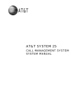
System Block Diagram and Board Layout
System Block Diagram
Chapter 5
81
Board Layout
Mainboard
Code
Component
Code
Component
JPWR2
8-pin ATX power connector
JUSB1-3
Front USB connectors
SYSFAN5
System fan 5 cable connector
J1394_1
IEEE 1394 connector
CPU
Processor socket
SYSFAN4
System fan 4 cable connector
CPUFAN
Processor fan cable connector
JCOM1
Serial port connector
Memory
System memory slots (DIMM 1 to 4)
JAUD1
Front panel audio connector
JPWR1
24-pin ATX power connector
JSP1
S/PDIF out connector
IDE1
IDE cable connector
Slots
SYSFAN3
System fan 3 cable connector
PCI Express x16 slot (PCI_E5)
SATA1-6
SATA data cable connectors
PCI 2.3 5V slot (PCI1)
SYSFAN2
System fan 2 cable connector
PCI Express x16 expansion slots
(supports PCI-E 2.0x 16 speed)
(PCI_E1 and PCI_E4)
JCI1
Chassis intrusion connector
PCI Express x1 slots (PCI_E2 and
PCI_E3)
PCI Express x8 slot (PCI_E6)
RESET1
Reset button
SYSFAN1
System fan 1 cable connector
F_PANEL1
Front panel connector
Back Panel
Refer to the Back Panel I/O table.
POWER1
Power button
82
Chapter 5
Back Panel I/O
Code
Color
Component
Mouse
Green
PS/2 mouse port
Keyboard
Purple
PS/2 keyboard port
1394 port
IEEE 1394 port (6-pin)
S/PDIF-out jack
S/PDIF port
eSATA ports
Blue
eSATA ports
Clear CMOS Button
CMOS reset button
LAN Jacks
Network ports
USB ports
USB ports
CS-Out
Orange
Center speaker/subwoofer jack (in 5.1/7.1 channel mode)
RS-Out
Black
Rear speaker/surround out jack (in 4/5.1/7.1 channel mode)
SS-Out
Gray
Side speaker/surround out jack (in 7.1 channel mode)
Line-In
Blue
Audio-in/line-in/side-surround out jack (in 7.1 channel mode)
This jack connects to an external CD player, tape player, or other audio
devices.
Line-Out
Green
Headphone/line-out/front speaker jack
This jack connects to speakers or headphones.
Mic
Pink
Microphone/line-in jack
This jack connects to a microphone.
Chapter 5
83
System Switches and Jumpers
Power Button
Press the power button (POWER1) on the mainboard to turn the system on or off.
Reset Button
Press this reset button (RESET1) on the mainboard to reset the system.
IDE Connector
The IDE connector (IDE1) supports IDE hard disk drives, optical disk drives, and other IDE devices.
IMPORTANT:If you install two IDE devices on the same cable, you must configure the drives separately to
master/slave mode by setting jumpers. Refer to IDE device's documentation supplied by the
vendors for jumper setting instructions.
84
Chapter 5
Serial ATA Connectors
The six serial ATA connectors (SATA1-6) is a high-speed Serial ATA interface port. Each connector can
connect to one Serial ATA device.
IMPORTANT:Please do not fold the Serial ATA cable into 90-degree angle. Otherwise, data loss may occur
during transmission.
Fan Power Connectors
The fan power connectors (CPUFAN and SYSFAN1-5) support system cooling fan with +12V. When
connecting the wire to the connectors, always note that the red wire is the positive and should be connected to
the +12V; the black wire is ground and should be connected to GND.
IMPORTANT:CPUFAN supports fan control. You can install Dual Core Center utility that will automatically
control the fan speed according to the actual CPU and system temperature. Fan/heat sink with 3
or 4 pins are both available for CPUFAN.
Chassis Intrusion Connector
The chassis intrusion connector (JCI1) connects to the chassis intrusion switch cable. If the chassis is opened,
the chassis intrusion mechanism will be activated. The system will record this status and show a warning
message on the screen. To clear the warning, you must enter the CMOS setup utility and clear the record.
Chapter 5
85
Front Panel Connector
The front panel connector (F_PANEL1) connects to the front panel switches and LEDs.
Pin
Signal
Description
1
Storage_LED +
Hard disk LED pull-up
2
FP PWR/SLP
MSG LED pull-up
3
Storage_LED -
Hard disk active LED
4
FP PWR/SLP
MSG LED pull-up
5
RST_SW -
Reset Switch low reference pull-down to GND
6
PWR_SW+
Power Switch high reference pull-down to GND
7
RST_SW+
Reset Switch high reference pull-up
8
PWR_SW-
Power Switch low reference pull-up
9
RSVD_DNU
Reserved. Do not use.
10
None
No pin
12
LAN_LED+
LAN LED pull-up
14
LAN_LED-
LAN LED pull-up
Serial Port Connector
The serial port connector (JCOM1) is a 16550A high speed communication port that sends/receives 16 bytes
FIFOs and connects to a serial device.
Serial port pin definition
86
Pin
Signal
Description
1
DCD
Data Carry Detect
2
SIN
Serial In or Receive Data
3
SOUT
Serial Out or Transmit Data
4
DTR
Data Terminal Ready
5
GND
Ground
6
DSR
Data Set Ready
7
RTS
Request To Send
8
CTS
Clear To Send
9
RI
Ring Indicate
Chapter 5
Power Connectors
The ATX 24-pin power connector (JPWR1) allows you to connect an ATX 24-pin or ATX 20-pin power supply.
When using a 20-pin ATX power supply, plug the power supply along with pins 1 and 13. A foolproof design is
on pins 11, 12, 23, and 24 to avoid wrong installation.
Pin
Signal
Pin
Signal
1
+3.3V
13
+3.3V
2
+3.3V
14
-12V
3
GND
15
GND
4
+5V
16
PS-ON#
5
GND
17
GND
6
+5V
18
GND
7
GND
19
GND
8
PWR OK
20
Res
9
5VSB
21
+5V
10
+12V
22
+5V
11
+12V
23
+5V
12
+3.3V
24
GND
The ATX 12V power connector (JPWR2) provides power to the processor.
Pin
Signal
Pin
Signal
1
GND
5
+12V
2
GND
6
+12V
3
GND
7
+12V
4
GND
8
+12V
Important notification about power issue
The NForce chipset is very sensitive to ESD (Electrostatic Discharge), therefore this issue mostly happens
while the users intensively swap memory modules under S5 (power-off) states, and the power cord is plugged
while installing modules. Due to several pins are very sensitive to ESD, so this kind of memory-replacement
actions might cause system chipset unable to boot.
Please follow the following solution to avoid this situation.
1.
Unplug the AC power cable.
2.
Unplug the ATX 24-pin and ATX 12V power connectors before the first installation or during system
upgrade procedure.
Chapter 5
87
Front USB Connector
The front USB connectors (JUSB1, JUSB2, and JUSB3) connects to high-speed USB interface peripherals.
Pin
Signal
Pin
Signal
1
VCC
6
USB1+
2
VCC
7
GND
3
USB0-
8
GND
4
USB1-
9
Key (no pin)
5
USB0+
10
USBOC
IEEE 1394 Connector
The IEEE 1394 connector (J1394_1) connects the IEEE1394 device via an optional IEEE1394 bracket.
Pin
Signal
Pin
Signal
1
TPA+
6
TPB-
2
TPA-
7
Cable power
3
Ground
8
Cable power
4
Ground
9
Key (no pin)
5
TPB+
10
Ground
S/PDIF-out Connector
The S/PDIF-out connector (JSP1) is used to connect S/PDIF interface for digital audio transmission.
88
Chapter 5
Front Panel Audio Connector
The front panel audio connector (JAUD1) connects the front panel audio.
HD audio pin definition
Pin
Signal
Description
1
MIC_L
Microphone - Left channel
2
GND
Ground
3
MIC_R
Microphone - Right channel
4
PRESENCE#
Active low signal-signals BIOS that a High Definition
Audio dongle is connected to the analog header.
PRESENCE# = 0 when a High Definition Audio
dongle is connected
5
LINE out_R
Analog Port - Right channel
6
MIC_JD
Jack detection return from front panel microphone
JACK1
7
Front_JD
Jack detection sense line from the High Definition
Audio CODEC jack detection resistor network
8
NC
No control
9
LINE out_L
Analog Port - Left channel
10
LINE out_JD
Jack detection return from front panel JACK2
AC’97 audio pin definition
Chapter 5
Pin
Signal
Description
1
MIC
Microphone input signal
2
GND
Ground
3
MIC_PWR
Microphone power
4
NC
No Control
5
LINE out_R
Right channel audio signal to front panel
6
NC
No Control
7
NC
No Control
8
Key
No pin
9
LINE out_L
Left channel audio signal to front panel
10
NC
No Control
89
CMOS Reset Button
The CMOS reset button located on the rear of the system, is powered by a battery on board to keep the
system configuration data. The CMOS RAM records the correct time and setting of system hardware
configuration. With the CMOS RAM, the system can automatically boot OS every time it is turned on. If you
want to clear the system configuration, use the CMOS reset button to clear data.
To clear the CMOS RAM:
NOTE: Make sure the system is powered off before performing the following instruction.
90
1.
Turn off the system and all the peripherals connected to it.
2.
Press the CMOS reset button located on the rear of the system. Refer to “Rear Panel” on page 6 for the
location of the CMOS reset button.
Chapter 5
Chapter 6
FRU (Field Replaceable Unit) List
This chapter offers the FRU (Field Replaceable Unit) list in global configuration of the desktop computer.
Refer to this chapter whenever ordering the parts to repair or for RMA (Return Merchandise Authorization).
NOTES:
Chapter 6
When ordering FRU parts, check the most up-to-date information available on your regional web
or channel. For whatever reasons a part number is changed, it will NOT be noted on the printed
Service Guide. For Acer authorized service providers, your Acer office may have a different part
number code from those given in the FRU list of this printed Service Guide. You MUST use the
local FRU list provided by your regional Acer office to order FRU parts for service.
To scrap or to return the defective parts, follow the local government ordinance or regulations on
how to dispose it properly, or follow the rules set by your regional Acer office on how to return it.
This document will be updated as more information about the FRU list becomes available.
91
Aspire G7700 Series Exploded Diagram
92
Chapter 6
ITEM
1
2
3
4
5
6
7
8
9
10
11
12
13
14
15
16
17
18
19
20
21
22
23
24
25
26
27
28
29
30
31
32
33
34
35
36
Chapter 6
PART NO.
60.3V218.002
86.00J10.A60
23.10240.001
33.3V207.001
54.13042.001
33.3V209.001
86.00E66.D60
42.3V218.001
60.3V208.001
60.3V212.001
60.3V207.001
42.3V203.001
42.3V204.001
33.3V205.001
50.3V203.001
42.3V229.001
42.3V223.001
42.3V222.001
42.3V224.001
42.3V226.001
42.3V225.001
60.3V210.001
60.3V220.001
42.3V201.001
60.3V209.001
60.3V217.001
60.3V216.001
60.3V204.001
33.3V203.001
60.3V205.001
42.3V230.001
42.3V201.001
42.3V202.001
60.3V206.001
60.3V213.001
42.3V231.001
60.3V215.001
60.3V214.001
PART NAME
ASSY BRKT REAR BRACKET AG900
SCREW M#6-32 L20 BZN
FAN 7150 BUMBLEBEE ANNIE HDD
BRKT LINKBAR UP BRACKET AG900
FRONT I/O BOARD YADB001-GP
BRKT FRONT IO BRACKET AG900
SCRW PAN M#6-32 L5 BZN
CVR FRONT IO COVER AG900
ASSY TOP COVER AG900
ASSY BRKT R-SIDE BRACKET AG900
ASSY SIDE COVER RIGHT AG900
HINGE FRONT COVER RIGHT 1
HINGE FRONT COVER RIGHT 2
AG900-BKT-MB-BRACKET
C.A. LED SWITCH CABLE
HOLDER POWER KNOB AG900
LENS POWER AG900
KNOB POWER AG900
KNOB ODD AG900
DOOR ODD RIGHT AG900
DOOR ODD LEFT AG900
ASSY FRONT COVER AG900
ASSY HDD DOOR AG900
LBL CARD READER LABEL
ASSY FRONT BEZEL AG900
ASSY HDD CARRIER SATA AG900
ASSY BRKT 4HSP HDD CAGE AG900
ASSY FRONT STAND AG900
BRKT FRONT LOWER SIDE BRACKET
ASSY STAND BACK AG900
HOLDER SUPPORT VGA AG900
HINGE FRONT COVER LEFT 1
HINGE FRONT COVER LEFT 2
ASSY SIDE COVER LEFT AG900
ASSY BRKT L-SIDE BRACKET AG900
HOLDER FAN DUCK UP AG900
ASSY BRKT HDD BRACKET AG900
ASSY BRKT ODD CAGE AG900
QTY
1
4
1
2
1
1
4
1
4
1
1
1
1
1
1
1
1
1
2
2
2
1
1
1
1
4
1
1
1
1
1
1
1
1
1
1
1
1
93
Aspire G7700 Series (81.3V201.001G)
Component
Part Name
Description
Acer
Part Number
System board
MB NVIDIA G9000 C72XE/
MARVELL
MB NVIDIA G9000 C72XE/MARVELL
MB.SAS01.002
IC CPU YORKFIELD QX9650
3.0G
IC CPU YORKFIELD QX9650 3.0G
KC.96501.QX0
IC CPU YORKFIELD Q9300
2.5G
IC CPU YORKFIELD Q9300 2.5G
KC.93001.QQ0
IC CPU KENTSFIELD Q6600
2.4G
IC CPU KENTSFIELD Q6600 2.4G
KC.66001.QQG
ASSY BUMBLEBEE LC
ASETEK
ASSY BUMBLEBEE LC ASETEK
60.3V201.001
FAN 12038 BUMBLEBEE
ANNIE
FAN 12038 BUMBLEBEE ANNIE
23.10239.001
VGA CARD NV 8800GT
512MB DDR3
VGA CARD NV 8800GT 512MB DDR3
VG.PC88G.T05
VGA CARD NV 8800GT
512MB DDR3
VGA CARD NV 8800GT 512MB DDR3
VG.PC88G.T06
DIMM 1G NT1GT64U8HB0BY25D
DIMM 1G NT1GT64U8HB0BY-25D
KN.1GB03.020
DIMM 2G
GU342G0ALEPR692C6CE
DIMM 2G GU342G0ALEPR692C6CE
KN.2GB0H.004
DIMM 2G TX1066QLU-2G
DIMM 2G TX1066QLU-2G
KN.2GB0F.002
HAUPPAUGE WINTV-HVR1200, HYBI
HAUPPAUGE WINTV-HVR-1200, HYBI
TV.AMIKI.SR2
TV TUNER CARD PE585QA
PCI-E HY
TV TUNER CARD PE585QA PCI-E HY
TU.10500.009
WLAN 802.11G WP61R2
WLAN 802.11G WP61R2
NI.10200.005
MB NVIDIA G9000 C72XE/
MARVELL
MB NVIDIA G9000 C72XE/MARVELL
MB.SAS01.002
MB NVIDIA G9000 C72XE/
MARVELL
MB NVIDIA G9000 C72XE/MARVELL
23.10240.001
CPU
Liquid cooler
VGA
Memory
TV Tuner
Wireless LAN
Audio Board
System fan
94
Chapter 6
Component
Part Name
Description
Acer
Part Number
Power
SPS 750W PFC GPS-750AB
A
SPS 750W PFC GPS-750AB A
PY.75009.001
BUMBLEBEE BACK PLANE
BD-1 SKU2
BUMBLEBEE BACK PLANE BD-1 SKU2
81.3V210.002G
BUMBLEBEE BACK PLANE
BD-1 SKU3
BUMBLEBEE BACK PLANE BD-1 SKU3
81.3V210.003G
BUMBLEBEE BACK PLANE
BOARD-1
BUMBLEBEE BACK PLANE BOARD-1
81.3V210.004G
CARD READER 3.5", USB2.0,
14-I
CARD READER 3.5", USB2.0, 14-I
CR.10400.008
CARD READER 3.5", USB2.0,
14-I
CARD READER 3.5", USB2.0, 14-I
CR.10400.009
HLDS SUPER MULTI SATA
GH-15N BOXER
HLDS SUPER MULTI SATA GH-15N
BOXER
KU.0160D.034
PLDS SUPER MULTI SATA
DH-16A3S BOXE
PLDS SUPER MULTI SATA DH-16A3S
BOXE
KU.01609.005
Sony SUPER-MULTI 16X
SATA AD-7200S
Sony SUPER-MULTI 16X SATA AD-7200S
KU.0160E.002
HLDS BD 4X HLDS GGCH20N BOXER
HLDS BD 4X HLDS GGC-H20N BOXER
KV.0040D.001
WD HDD 250GB WD
WD2500AAJS-22B4A0
WD HDD 250GB WD WD2500AAJS22B4A0
KH.25008.020
WD HDD 320GB WD
WD3200AAJS-22B4A0
WD HDD 320GB WD WD3200AAJS22B4A0
KH.32008.014
HGST HDD 500GB HGST
HDP725050GLA380
HGST HDD 500GB HGST
HDP725050GLA380
KH.50007.003
HGST 750GB SATA 8MB
7200 NCQ
HGST 750GB SATA 8MB 7200 NCQ
KH.75007.001
WD HDD WD 750GB SATA
8MB 7200 NCQ
WD HDD WD 750GB SATA 8MB 7200 NCQ
KH.75008.001
HGST 1TB SATA 8MB 7200
NCQ
HGST 1TB SATA 8MB 7200 NCQ
KH.01K07.001
ASSY BRKT 4HSP HDD
CAGE AG900
ASSY BRKT 4HSP HDD CAGE AG900
60.3V216.001
ASSY HDD CARRIER SATA
AG900
ASSY HDD CARRIER SATA AG900
60.3V217.001
HDD board
Card reader
Optical drive
Hard disk drive
Chapter 6
95
Component
Part Name
Description
Acer
Part Number
Housing
ASSY MAIN CHASSIS
AG900 A
ASSY MAIN CHASSIS AG900 A
60.3V202.001
ASSY FRONT STAND AG900
ASSY FRONT STAND AG900
60.3V204.001
ASSY STAND BACK AG900
ASSY STAND BACK AG900
60.3V205.001
ASSY SIDE COVER LEFT
AG900
ASSY SIDE COVER LEFT AG900
60.3V206.001
ASSY BRKT L-SIDE
BRACKET AG900
ASSY BRKT L-SIDE BRACKET AG900
60.3V214.001
ASSY SIDE COVER RIGHT
AG900
ASSY SIDE COVER RIGHT AG900
60.3V207.001
ASSY FRONT COVER AG900
ASSY FRONT COVER AG900
60.3V210.001
ASSY TOP COVER AG900
ASSY TOP COVER AG900
60.3V208.001
ASSY FRONT BEZEL AG900
ASSY FRONT BEZEL AG900
60.3V209.001
HINGE FRONT COVER LEFT
1
HINGE FRONT COVER LEFT 1
42.3V201.001
HINGE FRONT COVER LEFT
2
HINGE FRONT COVER LEFT 2
42.3V202.001
HINGE FRONT COVER
RIGHT 1
HINGE FRONT COVER RIGHT 1
42.3V203.001
HINGE FRONT COVER
RIGHT 2
HINGE FRONT COVER RIGHT 2
42.3V204.001
HOLDER POWER KNOB
HOLDER POWER KNOB
42.3V229.001
C.A. LED SWITCH CABLE
C.A. LED SWITCH CABLE
50.3V203.001
LED cable
96
Chapter 6
Component
Part Name
Description
Acer
Part Number
Assembly box
POWER CORD 1800MM
250V EURO
POWER CORD 1800MM 250V EURO
27.01518.0J1
POWER CORD 1800MM
250V UK
POWER CORD 1800MM 250V UK
27.03118.031
POWER CORD 250V BRAZIL
POWER CORD 250V BRAZIL
27.01518.0R1
CORD VCTF 3G 7A/
125V(JAPAN)
CORD VCTF 3G 7A/125V(JAPAN)
27.01518.181
POWER CORD ACA WITH
TESTED TAG
POWER CORD ACA WITH TESTED TAG
27.01518.0N1
POWER CORD 110V TW
POWER CORD 110V TW
27.01518.0M1
POWER CORD 110V UL USA
POWER CORD 110V UL USA
27.01518.0I1
POWER CORD 250V CCC
1800MM PRC
POWER CORD 250V CCC 1800MM PRC
27.01518.0K1
KB USB G15 920-001383
LOGI 109
KB USB G15 920-001383 LOGI 109
N/A
Logitech G5_USB
Logitech G5_USB
N/A
WL USB DONGLE 802.11G
WU61RL
WL USB DONGLE 802.11G WU61RL
NI.10200.002
BAG EPE+PE
860*800*0.5MM
BAG EPE+PE 860*800*0.5MM
42.3ZM.07.002
CTN AB 665*365*665MM
BUMBLEBEE
CTN AB 665*365*665MM BUMBLEBEE
44.3V201.011
ACCESSORY BOX
BUMBLEBEE
ACCESSORY BOX BUMBLEBEE
44.3V202.011
CUSHION EPE B
655*355*150
CUSHION EPE B 655*355*150
47.3V201.001
CUSHION EPE T
655*355*150
CUSHION EPE T 655*355*150
47.3V202.001
PAD EPE 380*180*2
PAD EPE 380*180*2
47.3V208.001
PAD B BUMBLEBEE
PAD B BUMBLEBEE
47.3V210.001
ACCESSORY TRAY EPE
BUMBLEBEE
ACCESSORY TRAY EPE BUMBLEBEE
47.3V211.001
SHEET PE 1600*1600*0.04
SHEET PE 1600*1600*0.04
42.73D05.001
CORNER KRAFT
1000*50*50*3 M1KC
CORNER KRAFT 1000*50*50*3 M1KC
46.30S04.001
PAPER CORNER
2200*50*50*3
PAPER CORNER 2200*50*50*3
46.3ZT01.001
PALLET PLYWOOD
1350*1140*135MM
PALLET PLYWOOD 1350*1140*135MM
47.3V209.001
Packing
Chapter 6
97
98
Chapter 6
Appendix A
Technical Specifications
This section provides technical specifications for the system.
Processor
Item
Specification
Type
Intel Core 2 Extreme
Intel Core 2 Quad
Model Number
QX9650
Q9300
Q6600
Core
Quad (45 nm)
Quad (45 nm)
Quad (65 nm)
L2 Cache Size (MB)
12
6
8
Clock Speed (GHz)
3
2.5
2.4
Front Side Bus (MHz) 1333
1333
1066
Frequency (MHz)
3000
2500
2400
Socket
LGA 775
LGA 775
LGA 775
Clock Multiplier
9x
7.5x
9x
Voltage (V)
0.85 - 1.3625
0.85 - 1.3625
1.1 - 1.372
Thermal Design
Power (W)
130
95
105 / 95
System Board Major Chips
Item
Specification
North bridge
NVIDIA nForce 780i SLI chipset
South bridge
NVIDIA nForce 570i SLI chipset
System Memory
Item
Specification
DIMM sockets
2
Minimum memory
512 MB
Maximum memory
2 GB
Vendor
Nanya
Unifosa
Transcend
Model name
NT1GT64U8HB0BY-25D
GU342G0ALEPR692C6CE
TX1066QLU-2G
DIMM size
1
2
2
DIMM speed (MHz)
800
800
800
ECC or non-ECC
Non-ECC
Non-ECC
Non-ECC
Speed
400 MHz
DDR2-800
DDR2-800
DDR2-800
PC2-6400
Pin count
Appendix A
240
PC2-6400
240
240
99
System BIOS
Item
Specification
BIOS vendor
American Megatrends Inc.
PCI Interface
Item
Specification
PCI controller
NVIDIA nForce 570i SLI chipset
Number of slots
•
Three PCI Express x16 bus slots
•
Two PCI Express x 1 slot
•
PCI Express x8 slot
•
PCI 2.3 slot (support 5V PCI bus interface)
Network Interface
Item
Specification
LAN controller
Marvell 88E8056B1
Supports LAN protocol
10/100/1000 Mbps
LAN connector type
RJ45
IDE Interface
Item
Specification
IDE controller
IDE1: NVIDIA nForce 570i SLI
IDE2: JMicron JMB363
Ultra DMA
66, 100, 133
SATA Interface
Item
Specification
SATA controller
Embedded SATA controller
Connectors
•
Six SATA ports
•
Two eSATA ports
Audio Interface
100
Item
Specification
Audio controller
Azalia Codec ALC888
Connectors
Up to 7.1 CH EAX 5.0 surround sound
Appendix A
IEEE 1394 Interface
Item
Specification
IEEE 1394 controller
JMicron JMB381
Connectors
Front and rear ports
Optical Drive
BD-R
Item
Specification
Vendor
HLDS
Model name
GGW-H20N
GGC-H20N
Drive type
BD-R
BD-R
Write Speed
BD-R(SL) 2x, 4x CLV
BD-R(DL)/BD-RE(SL/DL) 2x CLV
DVD-R 2x, 4x CLV, 8x ZCLV
DVD-R(DL) 2x, 4x CLV
DVD-RW 2x, 4x CLV, 6x ZCLV
DVD+R 2.4x, 4x CLV, 8x ZCLV
DVD+R(DL) 2.4x, 4x CLV
DVD+RW 2.4x, 4x, 6x CLV, 8x ZCLV
CD-R 10x CLV, 16x CLV
CD-RW 4x, 10x, 16x CLV
DVD-RAM 5x PCAV
DVD+R (DL) 4x CLV
DVD+RW 8x ZCLV
DVD+R 16x PCAV
DVD-R (DL) 4x CLV
DVD-RW 6x CLV
DVD-R 16x PCAV
CD-RW 24x ZCLV
CD-R 40x PCAV
Read Speed
BD-ROM(SL) 4x max. CAV
BD-ROM(DL) 3.2x max. CAV
BD-R(SL) 4x max. CAV
BD-R(DL)/BD-RE(SL/DL) 3.2x max.
CAV
HD DVD-ROM(SL) 3x max. CAV
HD DVD-ROM(DL) 2.4x max. CAV
DVD-R/RW/ROM(SL/DL) 10x / 8x /
12x / 8x max. CAV
DVD-R DL 6x max. CAV
DVD-Video (CSS Compliant Disc) 6x
max. (Single/Dual layer) CAV
DVD+R/+RW 10x / 8x max. CAV
DVD+R DL 6x max. CAV
CD-R/RW/ROM 32x / 24x / 32x max.
CAV
CD-DA (DAE) 24x max. CAV
HD DVD 3x
BD 6x
DVD 16x
CD 40x
Data Transfer Rate
BD-ROM 143.86 Mbits/s (4x) max
HD DVD-ROM 109.65 Mbits/s (3x)
max
DVD-ROM 16.62 Mbytes/s (12x) max
CD-ROM 4,800 Kbytes/s (32x) max
—
Access Time
BD-ROM 370 ms typ
HD DVD-ROM 340 ms typ
DVD-ROM 270 ms typ
CD-ROM 250 ms typ
—
Buffer Size
4 MB
4 MB
Interface Type
Serial ATA
Serial ATA
Appendix A
101
Super Multi
102
Item
Specification
Vendor
HLDS
Philips
Sony
Model name
GH-15N
DH-16A3S
AD-7200S
Drive type
Super Multi
Super Multi
Super Multi
Write Speed
—
—
DVD-R: 18x max.
DVD +R DL: 8x max.
DVD -R DL: 12x max.
DVD+RW: 8x max.
DVD-RW: 6x max.
DVD-RAM: 12x max.
CD-R: 48x
CD-RW: 32x
Read Speed
—
—
DVD: 16x max.
CD: 48x max.
Data Transfer Rate
—
—
—
Access Time
—
—
DVD: 160 ms
CD: 140 ms
Buffer Size
4 MB
4 MB
2 MB
Interface Type
Serial ATA
Serial ATA
Serial ATA
Appendix A