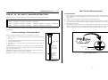
1
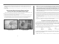
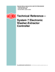
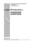
Published Manual Number/ECN: H28 0010/2001074N
• Publishing System: TPAS
• Access date: 2/14/01
• Document ECN's: Latest Available
Kit Instruction—
K28 0010
K36 0005
K36 0005R
PELLERIN MILNOR CORPORATION
POST OFFICE BOX 400, KENNER, LOUISIANA 70063-0400, U.S.A.
Please Read
About the Manual Identifying Information on the Cover
The front cover displays pertinent identifying information for this manual. Most important, are
the published manual number (part number) /ECN (date code). Generally, when a replacement
manual is furnished, it will have the same published manual number, but the latest available ECN.
This provides the user with the latest information applicable to his machine. Similarly all
documents comprising the manual will be the latest available as of the date the manual was
printed, even though older ECN dates for those documents may be listed in the table of
contents.
When communicating with the Milnor factory regarding this manual, please also provide the
other identifying information shown on the cover, including the publishing system, access date,
and whether the document ECN’s are the latest available or exact.
References to Yellow Troubleshooting Pages
This manual may contain references to “yellow pages.” Although the pages containing
troubleshooting procedures are no longer printed on yellow paper, troubleshooting instructions, if
any, will be contained in the easily located “Troubleshooting” chapter or section. See the table of
contents.
Trademarks of Pellerin Milnor Corporation
The following, some of which may be used in this manual, are trademarks of Pellerin Milnor
Corporation:
Ampsaver®
Autolint®
Auto-Purge®
Autovac
CBW®
Dye-Extractor®
Dyextractor®
E-P Express®
E-P OneTouch®
E-P Plus®
Gear Guardian®
Hands-Off®
Hydro-Cushion®
Mildata®
Milnet®
Milnor®
Miltrac
Miltron
Comments and Suggestions
Help us to improve this manual by sending your comments to:
Pellerin Milnor Corporation
Attn: Technical Publications
P. O. Box 400
Kenner, LA 70063-0400
Fax: (504) 469-1849
Staph-Guard®
System 4®
System 7®
Totaltrol®
1
2
Deflection Distance Scale
(Read Up)
Deflection
Force Scale
(Read Down)
ÎFIGURE 1 (MSSM0204AE)
ÎTension Tester Scales
Lower
o-ring
Upper
o-ring
3. Compare this value with the acceptable range in the appropriate table.
If the belt is brand new (has never been run), use the range in the Initial Tension column. If the belt is not brand new, locate the acceptable range in the Final Tension column.
2. Read the setting of the upper o-ring on the LBS scale of the tension
tester.
1. Place a straight edge along the top edge of the belt to be tested so that
it spans both pulleys. Place the tension tester in the center of the belt
and press and down on the cap until the lower o-ring is in line with
the straight edge, as shown.
Belt Tension Measurements
Ë
NOTE 3: The reference (ref.) codes shown in the tables are for factory use
only.
Î IGURE 2 (MSSM0204AE)
F
ÎTaking Measurements with the
Tension Tester
Lower
o-ring
Straight
Edge
NOTE 2: The instruction sheet provided with the tension testing device should not be used. Use only the instructions provided herein.
NOTE 1: The tension testing device is marked on the one side in inches and pounds and on the other side in centimeters and kilograms. All values in the tables are marked.
3. Move the lower o-ring on the tension tester to this deflection setting on the inches scale.
2. Find the proper belt deflection setting (by machine model and belt function) in the appropriate table below.
1. Move the upper o-ring to the topmost position, resting against the bottom
edge of the cap.
Set the o-rings on the tension testing device (see FIGURE 1) as follows:
Tension Settings
Ê
This instruction is to be used for adjusting the belt tension on the following
machine modes:
30016BWE
42026QHE
36021BWE
42026QTG
360326QWE
42026QTH
42026QWE
A belt tension testing device (Milnor® part number 30T001) and a straight
edge are required when using these instructions.
È-BELT TENSION ADJUSTMENTS FOR 30" AND 36" B-TYPE
V
MACHINES AND 42" Q-TYPE MACHINES
MSSM0204AE/8332BV (1 of 1)
5/32
11/64
LOW
SPEED
EXTRACT
MP3
LP3
MP3
EP2
MP3
DP2
MN
LN
NN
EN
MN
DN
KN
7.4 – 10.0
6.2 – 8.5
7.4 – 10.0
2.4 – 3.34
7.4 – 10.0
2.0 – 2.4
MN
LN
MN
EN
MN
DN
Initial
Tension (lbs.)
(ref.)
7.4 – 10.0
6.2 – 8.5
8.1 – 11.0
2.4 – 3.37
7.4 – 10.0
2.0 – 2.4
5.1 – 7.1
Initial
Tension
(lbs.)
(ref.)
15/32
60C
19/64
31/64
50C
5/32
19/64
Belt Defl.
(inches)
8.0 – 11.0
10.5 – 14.3
10.5 – 14.3
9.62 – 13.0
LP3
NP3
MP3
Initial Tension
(lbs.)
(ref.)
DP2
DP2
2 – 2.4
2 – 2.4
EP2
2.4 – 3.4
KP3
5.1 – 7.1
KN
MN
NN
EN
MN
DN
DN
EP2
MP3
6.6 – 9.2
KP3
8.1 – 11.0
8.1 – 11.0
LN
NN
MN
5.1 – 7.1
MP3 7.4 – 10.0
9.6 – 13.0 MP3 7.4 – 10.0
7.4 – 10.0
6.2 – 8.5
2.4 – 3.4
7.4 – 10.0
9.6 – 13.0 NP3 8.1 – 11.0
10.5 – 14.3
2.8 – 4.0
9.6 – 13.0
KN
MN
MN
NN
EN
MN
Initial
Initial
Tension
Tension
(ref.)
(lbs.)
(ref.) (lbs.)
42026QWE
6.6 – 9.2
9.6 – 13.0 MP3 7.4 – 10.0
10.5 – 14.3 NP3 8.1 – 11.0
2.8 – 4.0
9.6 – 13.0 MP3 7.4 – 10.0
2.4 – 2.8
2.4 – 2.8
Initial
Initial
Tension
Tension
(lbs.)
(ref.) (lbs.)
(ref.)
36021BWE
Final Tension
(lbs.)
(ref.)
1/4
1/4
7/16
7/16
23/64
23/64
23/64
11/32
Belt
Deflect
(IN)
11/64
11/64
27/64
27/64
13/32
25/64
13/32
13/32
Belt
Deflect
(IN)
Ï42026QHE, QTG, QTH
9.6 – 13.0
8.0 – 11.0
9.6 – 13.0
2.8 – 4.0
9.6 – 13.0
2.4 – 2.84
OPTIONAL LOW
SPEED EXRACT
MAIN
DRAIN
MP3
LP3
NP3
EP2
MP3
DP2
KP3
Initial
Tension
(lbs.)
(ref.)
9.0 – 13.0
8.0 – 11.0
WASH/
2 SPEED WASH
3/16
7/16
60C
60C
7/16
50C
3/16
13/32
60C
50C
25/64
50C
DRAIN
HIGH
SPEED
EXTRACT
13/32
13/32
Belt
Deflect.
(inches)
2.8 – 4.0
10.5 – 14.3
Ï36026QWE
60C
50C
25/64
60C
WASH/ 2
50C
SPEED WASH
60C
LOW
SPEED
EXTRACT
25/64
11/32
60C
50C
5/16
50C
DRAIN
HIGH
SPEED
EXTRACT
2.4 – 2.84
11/32
9.6 – 13.0
6.6 – 9.2
5/16
Initial
Tension
(lbs.)
(ref.)
WASH/ 2
50C
SPEED WASH
60C
Belt
Deflect.
(inches)
Ï30016BWE
4. If the reading on the tension tester is less than the range shown in the table, the belt is too loose and must be
tightened. If the reading is greater than the range shown in the table, the belt is too tight and must be loosened. Adjust the belt until the reading falls within the acceptable range in the table.
MSSM0301AE/9126BV
V-BELT TENSION ADJUSTMENTS
È
1. Place a straight edge along the top edge of the belt to be
tested so that it spans both pulleys. Place the tension
tester in the center of the belt and press down on the cap
until the lower o-ring is in line with the straight edge, as
shown.
This instruction is to be used for adjusting the belt tension on the following machine models:
42031WE2
42031SG2
42031WE3
42031SG3
42044WE2
42044SG2
42044WE3
42044SG3
Belt Tension Measurements
Ê
2. Read the setting of the upper o-ring on the lbs scale of the
tension tester.
A belt tension testing device (Milnor® part number 30T001) and a straight edge are required when using these
instructions.
Tension Settings
Ê
3. Compare this value with the acceptable range in the appropriate table. If the belt is brand new (has never been
run), use the range in the Initial Tension column. If the
belt is not brand new, locate the acceptable range in the
Final Tension column.
1. Move the upper o-ring to the topmost position, resting against the
bottom edge of the cap.
2. Find the proper Belt Deflection setting (by machine model and belt
function) in the appropriate table in this section.
Upper o-ring
3. Move the lower o-ring on the tension tester to this deflection setting
on the inches scale.
Deflection
force scale
(read down)
NOTE 2: The instruction sheet provided with the tension testing
device should not be used. Use only the instructions provided herein.
NOTE 3: The reference (ref) codes shown in the tables are for factory
use only.
3
Lower o-ring
ÎFIGURE 2 (MSSM0301AE)
ÎTaking Measurements with
the Tension Tester
4. If the reading on the tension tester is less than the range
shown in the table, the belt is too loose and must be tightened. If the reading is greater than the range shown
in the table, the belt is too tight and must be loosened. Adjust the belt until the reading falls within the acceptable range in the table.
Set the o-rings on the tension testing device (FIGURE 1) as follows:
NOTE 1: The tension testing device is marked on one side in inches
and pounds and on the other side in centimeters and kilograms. All
values in the tables are in inches (in) and pounds (lbs).
Straight edge
Ï42031WE2/WE3 and 42044WE2/WE3 Belt Tension Measurements
Belt Deflection
(inches)
Initial Tension
Final Tension
(LBS)
(REF)
(LBS)
(REF)
Wash/2-Speed Wash
11/64
9.6-13.0
MP3
7.4-10.0
MN
Drain
3/8
8.0-11.0
LP3
6.2-8.5
LN
10.5-14.3
NP3
8.1-11.0
NN
Lower o-ring
Deflection
distance scale
(read up)
Main
50Hz
9/16
60Hz
37/64
Ï42031SG2/SG3 and 42044SG2/SG3 Belt Tension Measurements
Belt Deflection
(inches)
Î IGURE 1 (MSSM0301AE)
F
ÎTension Tester Scales
Initial Tension
Final Tension
(LBS)
(REF)
(LBS)
(REF)
Wash/2-Speed Wash
11/64
9.6-13.0
MP3
7.4-10.0
MN
Drain
3/8
8.0-11.0
LP3
6.2-8.5
LN
E1 (optional)
11/32
9.6-13.0
MP3
7.4-10.0
MN
Upper Jackshaft 50Hz
to
Lower Jackshaft 60Hz
13/16
10.5-14.3
NP3
8.1-11.0
NN
13/16
MSSM0301AE/9126BV (1 of 1)
V-BELT TENSION ADJUSTMENTS
È
1. Place a straight edge along the top edge of the belt to be
tested so that it spans both pulleys. Place the tension
tester in the center of the belt and press down on the cap
until the lower o-ring is in line with the straight edge, as
shown.
This instruction is to be used for adjusting the belt tension on the following machine models:
42031WE2
42031SG2
42031WE3
42031SG3
42044WE2
42044SG2
42044WE3
42044SG3
Belt Tension Measurements
Ê
2. Read the setting of the upper o-ring on the lbs scale of the
tension tester.
A belt tension testing device (Milnor® part number 30T001) and a straight edge are required when using these
instructions.
Tension Settings
Ê
3. Compare this value with the acceptable range in the appropriate table. If the belt is brand new (has never been
run), use the range in the Initial Tension column. If the
belt is not brand new, locate the acceptable range in the
Final Tension column.
1. Move the upper o-ring to the topmost position, resting against the
bottom edge of the cap.
2. Find the proper Belt Deflection setting (by machine model and belt
function) in the appropriate table in this section.
Upper o-ring
3. Move the lower o-ring on the tension tester to this deflection setting
on the inches scale.
Deflection
force scale
(read down)
NOTE 2: The instruction sheet provided with the tension testing
device should not be used. Use only the instructions provided herein.
NOTE 3: The reference (ref) codes shown in the tables are for factory
use only.
Lower o-ring
ÎFIGURE 2 (MSSM0301AE)
ÎTaking Measurements with
the Tension Tester
4. If the reading on the tension tester is less than the range
shown in the table, the belt is too loose and must be tightened. If the reading is greater than the range shown
in the table, the belt is too tight and must be loosened. Adjust the belt until the reading falls within the acceptable range in the table.
Set the o-rings on the tension testing device (FIGURE 1) as follows:
NOTE 1: The tension testing device is marked on one side in inches
and pounds and on the other side in centimeters and kilograms. All
values in the tables are in inches (in) and pounds (lbs).
Straight edge
Ï42031WE2/WE3 and 42044WE2/WE3 Belt Tension Measurements
Belt Deflection
(inches)
Initial Tension
Final Tension
(LBS)
(REF)
(LBS)
(REF)
Wash/2-Speed Wash
11/64
9.6-13.0
MP3
7.4-10.0
MN
Drain
3/8
8.0-11.0
LP3
6.2-8.5
LN
10.5-14.3
NP3
8.1-11.0
NN
Lower o-ring
Deflection
distance scale
(read up)
Main
50Hz
9/16
60Hz
37/64
Ï42031SG2/SG3 and 42044SG2/SG3 Belt Tension Measurements
Belt Deflection
(inches)
Î IGURE 1 (MSSM0301AE)
F
ÎTension Tester Scales
Initial Tension
Final Tension
(LBS)
(REF)
(LBS)
(REF)
Wash/2-Speed Wash
11/64
9.6-13.0
MP3
7.4-10.0
MN
Drain
3/8
8.0-11.0
LP3
6.2-8.5
LN
E1 (optional)
11/32
9.6-13.0
MP3
7.4-10.0
MN
Upper Jackshaft 50Hz
to
Lower Jackshaft 60Hz
13/16
10.5-14.3
NP3
8.1-11.0
NN
13/16
4
MSSMA405AE/8737BV
Belt Tension Measurements
Ê
È-BELT TENSION ADJUSTMENTS
V
FOR 48", 52", 60" AND 72" WASHER-EXTRACTORS
Unbanded Belts
Ë
1. Place a straight edge along the top edge of the belt to be tested so that it spans both pulleys. Place the tension
tester in the center of the belt and press down on the cap until the lower o-ring is in line with the straight
edge, as shown.
This instruction is to be used for adjusting the belt tension on the following machine models:
48036QHE
48036QTG
48036QTH
2. Read the setting of the upper o-ring on the lbs scale of the tension tester.
60044WE3
3. Compare this value with the acceptable range in the appropriate table. If the belt is brand new (has never been
run), use the range in the Initial Tension column. If the belt is not brand new, locate the acceptable range in
the Final Tension column.
48032BHE
48032BTG
48032BTH
52038WE1
52038WTF
52038WTB 52038WTG 52038WTH
60036WE2
60036WE3
60036SG2
60036SG3
60044WE2
72044SG2
72044SG3
72044WE2
72044WE3
72044WTB 72044WTG 72044WTH
60044SG2
60044SG3
4. If the reading on the tension tester is less than the range shown in the table, the belt is too loose and must be
tightened. If the reading is greater than the range shown in the table, the belt is too tight and must be
loosened. Adjust the belt until the reading falls within the acceptable range in the table.
A belt tension testing device (Milnor® part number 30T001) and a straight edge are required when tensioning
unbanded belts.
Tension Settings—Unbanded Belts
Ê
Set the o-rings on the tension testing device (see FIGURE 1) as follows:
1. Move the upper o-ring to the topmost position, resting against the bottom edge
of the cap.
2. Find the proper belt deflection setting (by machine model and belt function) in
the appropriate table below.
Upper o-ring
3. Move the lower o-ring on the tension tester to this deflection setting on the inches scale.
NOTE 1: The tension testing device is marked on one side in inches and pounds
and on the other side in centimeters and kilograms. All values in the tables are in
inches (in.) and pounds (lbs.).
Deflection
force scale
(read down)
Lower o-ring
NOTE 2: The instruction sheet provided with the tension testing device should
not be used. Use only the instructions provided herein.
NOTE 3: The reference (ref.) code shown in the tables are for factory use only.
Deflection
distance
scale
(read up)
Lower o-ring
ÎFIGURE 1 (MSSMA405AE)
ÎTension Settings
5
Straight edge
ÎFIGURE 2 (MSSMA405AE)
ÎMeasuring Belt Tension
MSSMA405AE/8737BV
(1 of 2)
È-BELT TENSION ADJUSTMENTS
V
FOR 48", 52", 60" AND 72" WASHER-EXTRACTORS
Unbanded Belts
Ë
1. Place a straight edge along the top edge of the belt to be tested so that it spans both pulleys. Place the tension
tester in the center of the belt and press down on the cap until the lower o-ring is in line with the straight
edge, as shown.
This instruction is to be used for adjusting the belt tension on the following machine models:
48036QHE
48036QTG
Belt Tension Measurements
Ê
48036QTH
2. Read the setting of the upper o-ring on the lbs scale of the tension tester.
60044WE3
3. Compare this value with the acceptable range in the appropriate table. If the belt is brand new (has never been
run), use the range in the Initial Tension column. If the belt is not brand new, locate the acceptable range in
the Final Tension column.
48032BHE
48032BTG
48032BTH
52038WE1
52038WTF
52038WTB 52038WTG 52038WTH
60036WE2
60036WE3
60036SG2
60036SG3
60044WE2
72044SG2
72044SG3
72044WE2
72044WE3
72044WTB 72044WTG 72044WTH
60044SG2
60044SG3
4. If the reading on the tension tester is less than the range shown in the table, the belt is too loose and must be
tightened. If the reading is greater than the range shown in the table, the belt is too tight and must be
loosened. Adjust the belt until the reading falls within the acceptable range in the table.
A belt tension testing device (Milnor® part number 30T001) and a straight edge are required when tensioning
unbanded belts.
Tension Settings—Unbanded Belts
Ê
Set the o-rings on the tension testing device (see FIGURE 1) as follows:
1. Move the upper o-ring to the topmost position, resting against the bottom edge
of the cap.
2. Find the proper belt deflection setting (by machine model and belt function) in
the appropriate table below.
Upper o-ring
3. Move the lower o-ring on the tension tester to this deflection setting on the inches scale.
NOTE 1: The tension testing device is marked on one side in inches and pounds
and on the other side in centimeters and kilograms. All values in the tables are in
inches (in.) and pounds (lbs.).
Deflection
force scale
(read down)
Lower o-ring
NOTE 2: The instruction sheet provided with the tension testing device should
not be used. Use only the instructions provided herein.
NOTE 3: The reference (ref.) code shown in the tables are for factory use only.
Straight edge
Deflection
distance
scale
(read up)
ÎFIGURE 2 (MSSMA405AE)
ÎMeasuring Belt Tension
Lower o-ring
ÎFIGURE 1 (MSSMA405AE)
ÎTension Settings
6
Tensioning Banded Belts
Ë
Ï
Ï48032BHE, BTG, BTH
Belt
Deflect.
(inches)
48036QHE, QTG, QT
Initial
Tension
(lbs.)
(ref.)
Initial
Tension
(lbs.)
(ref.)
Belt
Deflect
(in.)
Initial
Tension
(lbs.)
(ref.)
Ï48032BHE, BTG, BTH
Initial
Tension
(lbs.)
(ref.)
Belt
Deflect.
(inches)
48036QHE, QTG, QT
Initial
Tension
(lbs.)
(ref.)
Initial
Tension
(lbs.)
(ref.)
Belt
Deflect
(in.)
Initial
Tension
(lbs.)
(ref.)
Initial
Tension
(lbs.)
(ref.)
WASH/
2 SPEED
WASH
9/32
6.6 - 9.2
KP3
5.1 - 7.1
KN
5/16
5.7 - 7.6
JP3
4.4 - 5.9
JN
WASH/
2 SPEED
WASH
1/4
5.7 - 7.6
JP3
4.4 - 5.9
JN
17/64
5.7 - 7.6
JP3
4.4 - 5.9
JN
DRAIN
5/32
5.7 - 7.6
JP3
4.4 - 5.9
JN
5/32
6.6 - 9.2
KP3
5.1 - 7.1
KN
DRAIN
3/64
6.6 - 9.2
KP3
5.1 - 7.1
KN
33/64
6.6 - 9.2
KP3
5.1 - 7.1
KN
E-1
9/32
6.6 - 9.2
KP3
5.1 - 7.1
KN
17/64
6.6 - 9.2
KP3
5.1 - 7.1
KN
10.5 - 14.3
NP3
8.1 - 11.0
NN
10.5 - 14.3
NP3
8.1 - 11.0
NN
17/32
E-2
39/64
6.6 - 9.2
KP3
5.1 - 7.1
KN
5/8
6.6 - 9.2
KP3
5.1 - 7.1
KN
3/16
UPPER JACK
TO
LOWER JACK
50C
.
35/64
MAIN
60C
.
LOW
SPEED
EXTRACT
17/32
17/32
13/64
6.6 - 9.2
KP3
5.1 - 7.1
KN
9.62 - 13.0
MP3
7.4 - 10.0
MN
BANDED
BELTS
NEED
SPECIAL
INSTRUCTIONS
LOWER JACK
TO
UPPER JACK
Ï52038WE1, WTF, WTB, WTG, WTH
Belt
Deflect.
(inches)
Initial
Tension
(lbs.)
(ref.)
60036 + 60044WE2 + WE3
Initial
Tension
(lbs.)
(ref.)
Belt
Deflect
(in.)
Initial
Tension
(lbs.)
(ref.)
25/64
10.5 - 14.3
NP3
8.1 - 11.0
NN
3/16
5.7 - 7.6
JP3
4.4 - 5.9
JN
DRAIN
5/32
10.5 - 14.3
NP3
8.1 - 11.0
NN
13/32
6.6 - 9.2
KP3
5.1 - 7.1
KN
E1
1/4
6.6 - 9.2
KP3
5.1 - 7.1
KN
17/64
6.6 - 9.2
KP3
5.1 - 7.1
KN
E2
1/2
6.6 - 9.2
KP3
5.1 - 7.1
KN
11/32
6.6 - 9.2
KP3
5.1 - 7.1
KN
50C
11/16
18.2 - 26.0
SP3
14.0 - 20.0
SN
43/64
60C
23/32
16.9 - 20.8
RP3
13.0 -16.0
RN
45/64
16.9 - 20.8
RP3
13.0 - 16.0
RN
MAIN
7
Ï52038WE1, WTF, WTB, WTG, WTH
Initial
Tension
(lbs.)
(ref.)
WASH/
2 SPEED
WASH
BANDED
BELTS
NEED
SPECIAL
INSTRUCTIONS
Belt
Deflect.
(inches)
Initial
Tension
(lbs.)
(ref.)
60036 + 60044WE2 + WE3
Initial
Tension
(lbs.)
(ref.)
Belt
Deflect
(in.)
Initial
Tension
(lbs.)
(ref.)
Initial
Tension
(lbs.)
(ref.)
WASH/
2 SPEED
WASH
15/64
5.7 - 7.6
JP3
4.4 - 5.9
JN
15/64
5.7 - 7.6
JP3
4.4 - 5.9
JN
DRAIN
13/32
6.6 - 9.2
KP3
5.1 - 7.1
KN
25/64
6.6 - 9.2
KP3
5.1 - 7.1
KN
E1
17/64
6.6 - 9.2
KP3
5.1 - 7.1
KN
17/64
6.6 - 9.2
KP3
5.1 - 7.1
KN
E2
5/16
6.6 - 9.2
KP3
5.1 - 7.1
KN
5/16
6.6 - 9.2
KP3
5.1 - 7.1
KN
50C
45/64
16.9 - 20.8
RP3
13.0 -16.0
RN
3/4
16.9 - 20.8
RP3
13.0 - 16.0
RN
60C
11/16
16.9 - 20.8
RP3
13.0 -16.0
RN
23/32
16.9 - 20.8
RP3
13.0 - 16.0
RN
MAIN
Tensioning Banded Belts
Ë
Ï
Ï48032BHE, BTG, BTH
Belt
Deflect.
(inches)
48036QHE, QTG, QT
Initial
Tension
(lbs.)
(ref.)
Initial
Tension
(lbs.)
(ref.)
Belt
Deflect
(in.)
Initial
Tension
(lbs.)
(ref.)
Ï48032BHE, BTG, BTH
Initial
Tension
(lbs.)
(ref.)
Belt
Deflect.
(inches)
48036QHE, QTG, QT
Initial
Tension
(lbs.)
(ref.)
Initial
Tension
(lbs.)
(ref.)
Belt
Deflect
(in.)
Initial
Tension
(lbs.)
(ref.)
Initial
Tension
(lbs.)
(ref.)
WASH/
2 SPEED
WASH
9/32
6.6 - 9.2
KP3
5.1 - 7.1
KN
5/16
5.7 - 7.6
JP3
4.4 - 5.9
JN
WASH/
2 SPEED
WASH
1/4
5.7 - 7.6
JP3
4.4 - 5.9
JN
17/64
5.7 - 7.6
JP3
4.4 - 5.9
JN
DRAIN
5/32
5.7 - 7.6
JP3
4.4 - 5.9
JN
5/32
6.6 - 9.2
KP3
5.1 - 7.1
KN
DRAIN
3/64
6.6 - 9.2
KP3
5.1 - 7.1
KN
33/64
6.6 - 9.2
KP3
5.1 - 7.1
KN
E-1
9/32
6.6 - 9.2
KP3
5.1 - 7.1
KN
17/64
6.6 - 9.2
KP3
5.1 - 7.1
KN
10.5 - 14.3
NP3
8.1 - 11.0
NN
10.5 - 14.3
NP3
8.1 - 11.0
NN
17/32
E-2
39/64
6.6 - 9.2
KP3
5.1 - 7.1
KN
5/8
6.6 - 9.2
KP3
5.1 - 7.1
KN
3/16
UPPER JACK
TO
LOWER JACK
50C
.
35/64
MAIN
60C
.
LOW
SPEED
EXTRACT
17/32
17/32
13/64
6.6 - 9.2
KP3
5.1 - 7.1
KN
9.62 - 13.0
MP3
7.4 - 10.0
MN
BANDED
BELTS
NEED
SPECIAL
INSTRUCTIONS
LOWER JACK
TO
UPPER JACK
Ï52038WE1, WTF, WTB, WTG, WTH
Belt
Deflect.
(inches)
Initial
Tension
(lbs.)
(ref.)
60036 + 60044WE2 + WE3
Initial
Tension
(lbs.)
(ref.)
Belt
Deflect
(in.)
Initial
Tension
(lbs.)
(ref.)
25/64
10.5 - 14.3
NP3
8.1 - 11.0
NN
3/16
5.7 - 7.6
JP3
4.4 - 5.9
JN
DRAIN
5/32
10.5 - 14.3
NP3
8.1 - 11.0
NN
13/32
6.6 - 9.2
KP3
5.1 - 7.1
KN
E1
1/4
6.6 - 9.2
KP3
5.1 - 7.1
KN
17/64
6.6 - 9.2
KP3
5.1 - 7.1
KN
E2
1/2
6.6 - 9.2
KP3
5.1 - 7.1
KN
11/32
6.6 - 9.2
KP3
5.1 - 7.1
KN
50C
11/16
18.2 - 26.0
SP3
14.0 - 20.0
SN
43/64
60C
23/32
16.9 - 20.8
RP3
13.0 -16.0
RN
45/64
16.9 - 20.8
RP3
13.0 - 16.0
RN
MAIN
Ï52038WE1, WTF, WTB, WTG, WTH
Initial
Tension
(lbs.)
(ref.)
WASH/
2 SPEED
WASH
BANDED
BELTS
NEED
SPECIAL
INSTRUCTIONS
Belt
Deflect.
(inches)
Initial
Tension
(lbs.)
(ref.)
60036 + 60044WE2 + WE3
Initial
Tension
(lbs.)
(ref.)
Belt
Deflect
(in.)
Initial
Tension
(lbs.)
(ref.)
Initial
Tension
(lbs.)
(ref.)
WASH/
2 SPEED
WASH
15/64
5.7 - 7.6
JP3
4.4 - 5.9
JN
15/64
5.7 - 7.6
JP3
4.4 - 5.9
JN
DRAIN
13/32
6.6 - 9.2
KP3
5.1 - 7.1
KN
25/64
6.6 - 9.2
KP3
5.1 - 7.1
KN
E1
17/64
6.6 - 9.2
KP3
5.1 - 7.1
KN
17/64
6.6 - 9.2
KP3
5.1 - 7.1
KN
E2
5/16
6.6 - 9.2
KP3
5.1 - 7.1
KN
5/16
6.6 - 9.2
KP3
5.1 - 7.1
KN
50C
45/64
16.9 - 20.8
RP3
13.0 -16.0
RN
3/4
16.9 - 20.8
RP3
13.0 - 16.0
RN
60C
11/16
16.9 - 20.8
RP3
13.0 -16.0
RN
23/32
16.9 - 20.8
RP3
13.0 - 16.0
RN
MAIN
8
9
MSSM0303AE/8451BV
È AIN BEARING AND SEAL REPLACEMENT
M
FOR DIVIDED CYLINDER MACHINES
This section applies to the front and rear cylinder shaft bearings of all divided cylinder machines (Rapid Load,
Staph-guard®, dye machines, etc.). It does not apply to jackshaft bearings, idler shaft bearings or bearings on open
pocket machines.
The bearings covered by this section are double row, spherical roller, self aligning bearings; Koya, SKF, FMC,
Torrington or equal. Referring to FIGURE 1, the rear (clean side on Staph-guard® models) bearing is firmly held
in the bearing housing (bearing and seal carrier) by the shaft seal holder, preventing axial movement. The front (soil
side on Staph-guard® models) bearing is free to move axially in the bearing housing to accommodate thermal
expansion of the shaft during operation and is thus the “floating” bearing. Both bearings are held in place on the
tapered portion of the shaft by a bearing lockwasher and locknut.
The front and rear bearings are each protected from contamination from wash water by three spring loaded,
lip type seals and a shaft seal leak-off cavity (that carries off any water that leaks past the main water seals) as shown
in FIGURE 1.
Access to the bearings and seals for lubrication is provided by the various grease passages. Excess lubricant is
excreted through the bearing and seal cavity leak-offs as shown on FIGURE 1. The bearings and seals must be
lubricated regularly and the leak-off cavities flushed out periodically through the plugged cleanout connections, in
strict accordance with the preventive maintenance procedures elsewhere.
If bearing replacement becomes necessary due to wear, it is essential that the bearings and seals are replaced.
Seal replacement requires removal of the bearing housing and seal sleeve. (In rare instances where the seals are
known to be in good condition, it is not necessary to remove the bearing housing, seals or seal sleeve when a bearing
is replaced.) A pulling fixture is required to remove the bearing housing. A set of guide rods, a seal sleeve
setting fixture and a bearing setting fixture are required for reinstallation of the housing. These tools are
available for rental or purchase from the Milnor® factory and are pictured elsewhere in this section. Contact the
factory two weeks in advance of repairs, when ordering these tools.
This maintenance is performed in the following order:
1. Remove old bearing(s). When removing both bearings, remove the front (soil side) bearing first.
2. Remove bearing housings, seal sleeves, and seals.
3. If both bearings were removed, install the bearing housing, seal sleeve, seals, and new bearing on the rear
(clean side).
Cap
Bolt
Bearing
Housing
(Bearing and
Seal Carrier)
Rear Bearing Assembly
Front Bearing Assembly
Shell
Rear
Shell
Front
Seal Sleeves
Bearing Cover
4. Install the bearing housing, seal sleeve, seals, and new bearing on the front (soil side).
Cap Bolt
5. Tighten bearing(s).
Bearing
Housing
(Bearing and
Seal Carrier)
See the Main Bearing Assembly drawing for your machine for bearing component part numbers.
Seal
Bearing
Lock-nut
Bearing
Lock-washer
Shaft Seal
Holder
Shaft
Front Bearing
(floating)
Seals
Bearing and Seal
Cavity Leak-offs
Shaft Seal
Leak-off
Cavities
Rear Bearing
(fixed)
Bearing and Seal
Cavity Leak-offs
ÎFigure 1 (MSSM0303AE)
Î ross Section View of Front and Rear Bearing Assemblies
C
(Bearing Assembly for 60" and 72" WED Shown. Others similar.)
10
Removing the Bearing (Front or Rear)
Ê
1. Loosen, then remove the main drive belts and
cylinder shaft pulley (if applicable) by lowering the
drive base with the jacking bolts. Do not attempt to
pry belts off with a pry bar or by rolling the sheave.
Remove the bearing cover (or shaft seal holder) to
expose the bearing.
2. Bend back the locking tang on the bearing lockwasher then remove the locknut and lockwasher.
3. The center tapped hole in the shaft end is an oil passage through which oil may be forced between the
tapered shaft and the bearing inner race. Install a
pipe fitting into this tapped hole as shown in figure
to the right. Using a “Porto-Power” or similar hand
operated hydraulic pump, force fluid into the passage. Pump hard to build up fluid pressure. This
pressure will cause the inner race to expand slightly; just enough to free the tapered surfaces and
allow the bearing to slip off easily. If the bearing is
not readily removed, remove the front water level
ÎFIGURE 2 (MSSM0303AE)
ÎConnection From Hydraulic Pump to
Assist in Bearing Removal
MSSM0303AE/8451BV
(1 of 5)
È AIN BEARING AND SEAL REPLACEMENT
M
FOR DIVIDED CYLINDER MACHINES
This section applies to the front and rear cylinder shaft bearings of all divided cylinder machines (Rapid Load,
Staph-guard®, dye machines, etc.). It does not apply to jackshaft bearings, idler shaft bearings or bearings on open
pocket machines.
The bearings covered by this section are double row, spherical roller, self aligning bearings; Koya, SKF, FMC,
Torrington or equal. Referring to FIGURE 1, the rear (clean side on Staph-guard® models) bearing is firmly held
in the bearing housing (bearing and seal carrier) by the shaft seal holder, preventing axial movement. The front (soil
side on Staph-guard® models) bearing is free to move axially in the bearing housing to accommodate thermal
expansion of the shaft during operation and is thus the “floating” bearing. Both bearings are held in place on the
tapered portion of the shaft by a bearing lockwasher and locknut.
The front and rear bearings are each protected from contamination from wash water by three spring loaded,
lip type seals and a shaft seal leak-off cavity (that carries off any water that leaks past the main water seals) as shown
in FIGURE 1.
Access to the bearings and seals for lubrication is provided by the various grease passages. Excess lubricant is
excreted through the bearing and seal cavity leak-offs as shown on FIGURE 1. The bearings and seals must be
lubricated regularly and the leak-off cavities flushed out periodically through the plugged cleanout connections, in
strict accordance with the preventive maintenance procedures elsewhere.
If bearing replacement becomes necessary due to wear, it is essential that the bearings and seals are replaced.
Seal replacement requires removal of the bearing housing and seal sleeve. (In rare instances where the seals are
known to be in good condition, it is not necessary to remove the bearing housing, seals or seal sleeve when a bearing
is replaced.) A pulling fixture is required to remove the bearing housing. A set of guide rods, a seal sleeve
setting fixture and a bearing setting fixture are required for reinstallation of the housing. These tools are
available for rental or purchase from the Milnor® factory and are pictured elsewhere in this section. Contact the
factory two weeks in advance of repairs, when ordering these tools.
This maintenance is performed in the following order:
1. Remove old bearing(s). When removing both bearings, remove the front (soil side) bearing first.
2. Remove bearing housings, seal sleeves, and seals.
3. If both bearings were removed, install the bearing housing, seal sleeve, seals, and new bearing on the rear
(clean side).
Cap
Bolt
Bearing
Housing
(Bearing and
Seal Carrier)
Rear Bearing Assembly
Front Bearing Assembly
Shell
Rear
Shell
Front
Seal Sleeves
Bearing Cover
4. Install the bearing housing, seal sleeve, seals, and new bearing on the front (soil side).
Cap Bolt
5. Tighten bearing(s).
Bearing
Housing
(Bearing and
Seal Carrier)
See the Main Bearing Assembly drawing for your machine for bearing component part numbers.
Seal
Bearing
Lock-nut
Bearing
Lock-washer
Shaft Seal
Holder
Shaft
Front Bearing
(floating)
Seals
Bearing and Seal
Cavity Leak-offs
Shaft Seal
Leak-off
Cavities
Rear Bearing
(fixed)
Bearing and Seal
Cavity Leak-offs
ÎFigure 1 (MSSM0303AE)
Î ross Section View of Front and Rear Bearing Assemblies
C
(Bearing Assembly for 60" and 72" WED Shown. Others similar.)
Removing the Bearing (Front or Rear)
Ê
1. Loosen, then remove the main drive belts and
cylinder shaft pulley (if applicable) by lowering the
drive base with the jacking bolts. Do not attempt to
pry belts off with a pry bar or by rolling the sheave.
Remove the bearing cover (or shaft seal holder) to
expose the bearing.
2. Bend back the locking tang on the bearing lockwasher then remove the locknut and lockwasher.
3. The center tapped hole in the shaft end is an oil passage through which oil may be forced between the
tapered shaft and the bearing inner race. Install a
pipe fitting into this tapped hole as shown in figure
to the right. Using a “Porto-Power” or similar hand
operated hydraulic pump, force fluid into the passage. Pump hard to build up fluid pressure. This
pressure will cause the inner race to expand slightly; just enough to free the tapered surfaces and
allow the bearing to slip off easily. If the bearing is
not readily removed, remove the front water level
11
ÎFIGURE 2 (MSSM0303AE)
ÎConnection From Hydraulic Pump to
Assist in Bearing Removal
inspection plate and use a timber to pry up the cylinder to remove cylinder weight from the bearings. Once
the bearing is removed, the cylinder drops only approximately 1/32" before the shaft comes to rest on the
shaft support.
4. Slide the bearing off of the shaft and if it is to be reused, place it on a clean surface and cover with a clean,
lint free cloth.
Removing the Bearing Housing (Bearing and Seal
Ê
Carrier), Seal Sleeve, and Seals (Front or Rear)
NOTE: Step 2a or 2b below will cause the bearing housing to slide away from the shell. Shims were placed
under one or more of the three bearing housing pads during factory assembly to align the housing and insure
its being exactly parallel with the shaft. When removing the bearing housing, be sure to keep these shims
separate and identified so that they may be returned to their proper location, otherwise the bearing
and seal will be out of line and may be damaged after a short operating period. As a precaution in case
the shims are lost during disassembly, you will find stamped next to the bearing housing the proper thickness
of shims required (if any) under each adjacent bearing housing pad. The stamped number indicates the shim
thickness in thousandths of an inch. For example, the number “38” indicates that 38/1000 (.038") shims
would be required under this pad.
These procedures require the use of a pulling fixture and guide rods available from the Milnor® factory. With
the bearing cover (or shaft seal holder) and the bearing removed, proceed as follows:
2a. Tighten all four hexnuts on the threaded rods such that the pulling fixture plate is pressed against the shaft
end. With an impact wrench, tighten down on the center bolt until the housing slides out, or
1. Remove the three bearing housing cap bolts and the grease lines from the bearing housing front plate. Install
guide rods in two of the bolt holes, as shown in FIGURE 3.
2b. If no impact wrench is available, simply continue to tighten down on each of the four hexnuts behind the
pulling fixture plate, alternately and progressively, until the housing slides out. It may be necessary to place
a spacer (approx. two inches long) between the plate and the shaft to provide enough clearance between the
plate and the bearing housing.
2. Install the pulling fixture as shown in FIGURE 4, by placing each of the four threaded rods through a hole in
the steel plate with hexnuts to the outside of the plate then screwing each rod into the appropriate tapped
hole in the bearing housing (same holes as used to mount the bearing cover or shaft seal holder).
3. Once the bearing housing is free of the shell, carefully slide it off of the guide rods and place on a clean work
surface.
4. The seal sleeve will almost always remain on the shaft when the housing is removed. Remove the seal sleeve
taking care not to damage or scar it and place it on a clean work surface.
Precautions for Bearing Replacement
Ê
The most important ingredient in successful bearing and seal installation is cleanliness. The bearing housing
must be free of all foreign matter. The grease and leak-off passages must be blown clear and all foreign matter
removed. You must have a clean work area. Keep your hands and tools free from grit and grime. Wash your hands
before starting and as required during these procedures. Foreign matter is, without doubt, the most frequent cause
of bearing failure, and one over which the manufacturer has no control.
Where cleaning is required, bearings, bearing housings and seal sleeves may be cleaned with the following
solvents or cleaning agents (in strict accordance with the manufacturer’s recommendations as such substances are
generally toxic and/or explosive under certain conditions):
ÎFIGURE 3 (MSSM0303AE)
ÎTwo Bearing Housing Guide
Rods in Position
ÎFIGURE 4 (MSSM0303AE)
ÎBearing Housing Pulling
Fixture in Position
Benzene
Chlorethane
Freons
Gasoline
Kerosene
Mineral Spirts
Naptha
Tricholorethylene
Do not, however, expose any components to the above substances for more than 24 hours and only use at room
temperature. Never use the following solvents or cleaning agents: alcohols, cresols, phenols, flouro propanols, or
other similar chemicals or mixtures.
NOTE: Hammer blows, overheating, or improper use of force can damage precision parts.
12
inspection plate and use a timber to pry up the cylinder to remove cylinder weight from the bearings. Once
the bearing is removed, the cylinder drops only approximately 1/32" before the shaft comes to rest on the
shaft support.
4. Slide the bearing off of the shaft and if it is to be reused, place it on a clean surface and cover with a clean,
lint free cloth.
Removing the Bearing Housing (Bearing and Seal
Ê
Carrier), Seal Sleeve, and Seals (Front or Rear)
NOTE: Step 2a or 2b below will cause the bearing housing to slide away from the shell. Shims were placed
under one or more of the three bearing housing pads during factory assembly to align the housing and insure
its being exactly parallel with the shaft. When removing the bearing housing, be sure to keep these shims
separate and identified so that they may be returned to their proper location, otherwise the bearing
and seal will be out of line and may be damaged after a short operating period. As a precaution in case
the shims are lost during disassembly, you will find stamped next to the bearing housing the proper thickness
of shims required (if any) under each adjacent bearing housing pad. The stamped number indicates the shim
thickness in thousandths of an inch. For example, the number “38” indicates that 38/1000 (.038") shims
would be required under this pad.
These procedures require the use of a pulling fixture and guide rods available from the Milnor® factory. With
the bearing cover (or shaft seal holder) and the bearing removed, proceed as follows:
2a. Tighten all four hexnuts on the threaded rods such that the pulling fixture plate is pressed against the shaft
end. With an impact wrench, tighten down on the center bolt until the housing slides out, or
1. Remove the three bearing housing cap bolts and the grease lines from the bearing housing front plate. Install
guide rods in two of the bolt holes, as shown in FIGURE 3.
2b. If no impact wrench is available, simply continue to tighten down on each of the four hexnuts behind the
pulling fixture plate, alternately and progressively, until the housing slides out. It may be necessary to place
a spacer (approx. two inches long) between the plate and the shaft to provide enough clearance between the
plate and the bearing housing.
2. Install the pulling fixture as shown in FIGURE 4, by placing each of the four threaded rods through a hole in
the steel plate with hexnuts to the outside of the plate then screwing each rod into the appropriate tapped
hole in the bearing housing (same holes as used to mount the bearing cover or shaft seal holder).
3. Once the bearing housing is free of the shell, carefully slide it off of the guide rods and place on a clean work
surface.
4. The seal sleeve will almost always remain on the shaft when the housing is removed. Remove the seal sleeve
taking care not to damage or scar it and place it on a clean work surface.
Precautions for Bearing Replacement
Ê
The most important ingredient in successful bearing and seal installation is cleanliness. The bearing housing
must be free of all foreign matter. The grease and leak-off passages must be blown clear and all foreign matter
removed. You must have a clean work area. Keep your hands and tools free from grit and grime. Wash your hands
before starting and as required during these procedures. Foreign matter is, without doubt, the most frequent cause
of bearing failure, and one over which the manufacturer has no control.
Where cleaning is required, bearings, bearing housings and seal sleeves may be cleaned with the following
solvents or cleaning agents (in strict accordance with the manufacturer’s recommendations as such substances are
generally toxic and/or explosive under certain conditions):
ÎFIGURE 3 (MSSM0303AE)
ÎTwo Bearing Housing Guide
Rods in Position
ÎFIGURE 4 (MSSM0303AE)
ÎBearing Housing Pulling
Fixture in Position
Benzene
Chlorethane
Freons
Gasoline
Kerosene
Mineral Spirts
Naptha
Tricholorethylene
Do not, however, expose any components to the above substances for more than 24 hours and only use at room
temperature. Never use the following solvents or cleaning agents: alcohols, cresols, phenols, flouro propanols, or
other similar chemicals or mixtures.
NOTE: Hammer blows, overheating, or improper use of force can damage precision parts.
13
Replacing the Bearing Housing, Seal Sleeve,
Ê
and Seals (Front or Rear)
1. With the seal sleeve removed, press all old seals out of the bearing housing. Remove the large o-ring from the
outside of the housing. Thoroughly clean the bearing housing and flush out all grease passages to make certain they are unblocked. Remove the o-rings from the inside of the seal sleeve and clean the seal sleeve.
2. While the bearing housing is dissassembled, charge all grease passages with grease. This will assure that there
are no blockages.
6. With two of the three temporary guide rods in position on the shell, place the bearing housing onto the guide
rods and install the seal sleeve setting fixture on to the bearing housing as shown in FIGURE 7. The seal
sleeve setting fixture prevents the seal sleeve from being pushed out of the housing as the housing is inserted into the shell. Note that the seal sleeve setting fixture and the bearing setting fixture are very similar,
but the seal sleeve setting fixture has a longer hub.
7. With a clean, lint free cloth, apply a coating of light machine oil to the outside of the housing, to assist in installation. Push the housing into the shell as shown in FIGURE 8. Once the housing is far enough into the
shell to support itself, place any shims back into position between the housing and the shell. Remove, then
replace guide rods if required to place shims under bearing housing pads.
3. Replace the o-rings in the seal sleeve and the large o-ring on the outside of the bearing housing. Replace with
new o-rings if the old ones are worn.
4. Press new seals into the bearing housing. You may gently work the seals in with a mallet and metal drift as
shown in FIGURE 5.
Each seal must be of the proper material and face the proper direction. The type of material
and direction the seal faces may differ from one seal to another within the same bearing
housing and also from one type of machine to another. It is essential to consult the Main
Bearing Assembly drawing for your machine for the proper part number and direction to
face each seal.
5. Slip the seal sleeve into the bearing housing as shown in FIGURE 6 below right, using care not to damage or
fold under any of the seal lips. Be sure to insert the sleeve in the proper direction (see Bearing Assembly drawing).
ÎFIGURE 7 (MSSM0303AE)
IÎnstalling the Bearing Housing Setting
Fixture onto Housing (42" machine shown)
ÎFIGURE 8 (MSSM0303AE)
Î ushing the Bearing Housing into the
P
Shell (60" Rapid-load machine shown)
8. Install the third guide rod, spacers if required, and hexnuts, using these to seat the housing fully, as shown
in FIGURE 9. Remove the seal sleeve setting fixture.
9. Remove the guide rods and install the bearing housing
cap bolts. See “BOLT TORQUE REQUIREMENTS” elsewhere, for proper torques.
10. With the grease gun, pump grease into the inner portion of the bearing cavity, such that when the bearing is installed, the space between the bearing and
the seals will be approximately 1/3 full of grease.
ÎFIGURE 5 (MSSM0303AE)
ÎInstalling Seals in
Bearing Housing
Î IGURE 6 (MSSM0303AE)
F
ÎInstalling Seal Sleeve in
Bearing Housing
NOTE: If both housings are being installed, install the rear housing first.
14
11 Proceed to “Measuring Unmounted Clearance . . .”
below, even if both the front and rear bearings are
being replaced. Once the rear bearing is installed,
the bearing housing replacement procedures may
then be repeated for the front (soil side) bearing housing.
ÎFIGURE 9 (MSSM0303AE)
Î ightening the Bearing Housing
T
into the Shell (42" machine shown)
Replacing the Bearing Housing, Seal Sleeve,
Ê
and Seals (Front or Rear)
1. With the seal sleeve removed, press all old seals out of the bearing housing. Remove the large o-ring from the
outside of the housing. Thoroughly clean the bearing housing and flush out all grease passages to make certain they are unblocked. Remove the o-rings from the inside of the seal sleeve and clean the seal sleeve.
2. While the bearing housing is dissassembled, charge all grease passages with grease. This will assure that there
are no blockages.
6. With two of the three temporary guide rods in position on the shell, place the bearing housing onto the guide
rods and install the seal sleeve setting fixture on to the bearing housing as shown in FIGURE 7. The seal
sleeve setting fixture prevents the seal sleeve from being pushed out of the housing as the housing is inserted into the shell. Note that the seal sleeve setting fixture and the bearing setting fixture are very similar,
but the seal sleeve setting fixture has a longer hub.
7. With a clean, lint free cloth, apply a coating of light machine oil to the outside of the housing, to assist in installation. Push the housing into the shell as shown in FIGURE 8. Once the housing is far enough into the
shell to support itself, place any shims back into position between the housing and the shell. Remove, then
replace guide rods if required to place shims under bearing housing pads.
3. Replace the o-rings in the seal sleeve and the large o-ring on the outside of the bearing housing. Replace with
new o-rings if the old ones are worn.
4. Press new seals into the bearing housing. You may gently work the seals in with a mallet and metal drift as
shown in FIGURE 5.
Each seal must be of the proper material and face the proper direction. The type of material
and direction the seal faces may differ from one seal to another within the same bearing
housing and also from one type of machine to another. It is essential to consult the Main
Bearing Assembly drawing for your machine for the proper part number and direction to
face each seal.
5. Slip the seal sleeve into the bearing housing as shown in FIGURE 6 below right, using care not to damage or
fold under any of the seal lips. Be sure to insert the sleeve in the proper direction (see Bearing Assembly drawing).
ÎFIGURE 7 (MSSM0303AE)
IÎnstalling the Bearing Housing Setting
Fixture onto Housing (42" machine shown)
ÎFIGURE 8 (MSSM0303AE)
Î ushing the Bearing Housing into the
P
Shell (60" Rapid-load machine shown)
8. Install the third guide rod, spacers if required, and hexnuts, using these to seat the housing fully, as shown
in FIGURE 9. Remove the seal sleeve setting fixture.
9. Remove the guide rods and install the bearing housing
cap bolts. See “BOLT TORQUE REQUIREMENTS” elsewhere, for proper torques.
10. With the grease gun, pump grease into the inner portion of the bearing cavity, such that when the bearing is installed, the space between the bearing and
the seals will be approximately 1/3 full of grease.
ÎFIGURE 5 (MSSM0303AE)
ÎInstalling Seals in
Bearing Housing
Î IGURE 6 (MSSM0303AE)
F
ÎInstalling Seal Sleeve in
Bearing Housing
NOTE: If both housings are being installed, install the rear housing first.
11 Proceed to “Measuring Unmounted Clearance . . .”
below, even if both the front and rear bearings are
being replaced. Once the rear bearing is installed,
the bearing housing replacement procedures may
then be repeated for the front (soil side) bearing housing.
15
ÎFIGURE 9 (MSSM0303AE)
Î ightening the Bearing Housing
T
into the Shell (42" machine shown)
Measuring Unmounted Clearance and
Ê
Setting Bearing (Front or Rear)
The bearings used on Milnor® washer and dye extractors are the very best anti-friction devices available for
these applications. However, the anti-frictional characteristics of the bearings will be reduced if they are not properly installed. It is of critical importance when installing these tapered roller bearings, to accomplish the following (A
step by step procedure follows this synopsis):
NOTE 1: The clearances listed in the chart are industry standards and therefore apply to all brands of
bearings supplied by Milnor®. If other sources of bearings are used, refer to the manufacturer’s instructions
for proper clearances.
NOTE 2: To locate your bearing on the chart, match the first five characters of the manufacturer’s part
number (not the Milnor® part number) with those in the chart. For example, for a manufacturer’s part
number 22217LBK, find under “Manufacturer Part Number” the line “22217 . . .”
ÏTable of Bearing Clearances
1. Accurately measure the unmounted internal clearance of the bearing (gap between the rollers and outer race
before the bearing is installed). This is an essential quality control measure.
2. Calculate the final internal clearance by subtracting the specified clearance reduction (amount that the internal
clearance must be reduced when the bearing is tightened onto the tapered shaft) from the unmounted
clearance.
3. Tighten the bearing onto the shaft until the final internal clearance as calculated is achieved and verified by
measurement.
These measurements are taken in thousandths of an inch. Although this requires precise work, attention to
detail and a good set of feeler gauges, it is the only way to insure that the bearing will be tightened onto the shaft to
precisely the right tension. If you have any questions on performing the measurements or adjustments described
below, your local bearing supplier or the Milnor® factory can assist you. Although these procedures require
precision over and above that normally required for laundry room maintenance, they are standard in bearing installation and absolutely essential:
NOTE: Step 1 which follows, requires a good set of feeler
gauges including .001" through .010" in thousandths of an inch
increments. Contact your local bearing supplier.
Minimum
Maximum
Minimum
Maximum
22330 . . .
.0071
.0091
.002
.003
22213 . . .
.0030
.0039
.001
.002
22216 . . .
.0028
.0037
.001
.002
22217 . . .
.0044
.0057
.0015
.0025
22312 . . .
.0030
.0039
.001
.002
22316 . . .
.0037
.0049
.001
.002
22320 . . .
.0044
.0057
.0015
.0025
22328 . . .
.0063
.0081
.002
.003
23220 . . .
.0044
.0057
.0015
.0025
5. Hand pack the bearing with grease by rotating the inner race and rollers, forcing grease between all rollers.
NOTE: The bearing will be set into position in Step 6. If both front and rear bearings are being installed,
the rear (clean side on Staph-guard® models) bearing should be set in position first because it is the fixed
bearing.
ÎFIGURE 10 (MSSM0303AE)
ÎMeasuring Bearing
Unmounted Clearance
(bridge for 42" machine shown)
3. Compare the measured clearance with the “Unmounted Clearance” in the table below. If the measured
clearance is not within the range shown, do not use the bearing. Contact your bearing supplier for an exchange.
16
Clearance Reduction
4. Calculate and record the final internal clearance by deducting the “Clearance Reduction” for your bearing (see
above chart) from the measured clearance. For example, if you measured .004 and the clearance reduction is
.001 to .002, then the final internal clearance should be between .002 and .003.
1. When you are ready to proceed (and not before) remove the
new bearing from it’s box or protective wrapping. Do not attempt to clean the bearing or wash out the preservative coating. On a clean work surface, stand the bearing on edge and
insert a .003 feeler gauge into the bearing as shown in FIGURE 10, at right. The gauge should be inserted just inside
the outer race between two rollers and worked through to the
opposite row of rollers. Rotate the inner race of the opposite
row so that the end of the feeler gauge is caught between a
roller and the outer race.
2. Try to pull the gauge straight out. If it comes out, increase the
size of the gauge by .001". If it does not come out, decrease
the gauge by .001". The thickest feeler gauge that will come
out is the unmounted internal clearance of the bearing.
Unmounted Clearance
Manufacturer Part Number
6. Set the bearing into the housing (with the taper facing the proper direction) and seat the bearing using the bearing setting fixture. This fixture is installed in similar fashion to the seal sleeve setting fixture. If you have
just set the rear bearing and the front bearing housing is yet to be installed, leave the bearing setting fixture
in place for now.
7. If you have just set the rear bearing and the front bearing housing is yet to be installed, repeat all steps in bearing housing installation, measuring unmounted clearance and setting bearing, for the front bearing and housing. The bearing setting fixture should not be removed from the rear housing until it is needed to seat the
front bearing. This will prevent rear bearing components from being pushed out of position by the shaft as
the front housing components are seated. Remove the bearing setting fixture from the front housing once the
bearing is seated.
Measuring Unmounted Clearance and
Ê
Setting Bearing (Front or Rear)
The bearings used on Milnor® washer and dye extractors are the very best anti-friction devices available for
these applications. However, the anti-frictional characteristics of the bearings will be reduced if they are not properly installed. It is of critical importance when installing these tapered roller bearings, to accomplish the following (A
step by step procedure follows this synopsis):
NOTE 1: The clearances listed in the chart are industry standards and therefore apply to all brands of
bearings supplied by Milnor®. If other sources of bearings are used, refer to the manufacturer’s instructions
for proper clearances.
NOTE 2: To locate your bearing on the chart, match the first five characters of the manufacturer’s part
number (not the Milnor® part number) with those in the chart. For example, for a manufacturer’s part
number 22217LBK, find under “Manufacturer Part Number” the line “22217 . . .”
ÏTable of Bearing Clearances
1. Accurately measure the unmounted internal clearance of the bearing (gap between the rollers and outer race
before the bearing is installed). This is an essential quality control measure.
2. Calculate the final internal clearance by subtracting the specified clearance reduction (amount that the internal
clearance must be reduced when the bearing is tightened onto the tapered shaft) from the unmounted
clearance.
3. Tighten the bearing onto the shaft until the final internal clearance as calculated is achieved and verified by
measurement.
These measurements are taken in thousandths of an inch. Although this requires precise work, attention to
detail and a good set of feeler gauges, it is the only way to insure that the bearing will be tightened onto the shaft to
precisely the right tension. If you have any questions on performing the measurements or adjustments described
below, your local bearing supplier or the Milnor® factory can assist you. Although these procedures require
precision over and above that normally required for laundry room maintenance, they are standard in bearing installation and absolutely essential:
NOTE: Step 1 which follows, requires a good set of feeler
gauges including .001" through .010" in thousandths of an inch
increments. Contact your local bearing supplier.
Clearance Reduction
Minimum
Maximum
Minimum
Maximum
22330 . . .
.0071
.0091
.002
.003
22213 . . .
.0030
.0039
.001
.002
22216 . . .
.0028
.0037
.001
.002
22217 . . .
.0044
.0057
.0015
.0025
22312 . . .
.0030
.0039
.001
.002
22316 . . .
.0037
.0049
.001
.002
22320 . . .
.0044
.0057
.0015
.0025
22328 . . .
.0063
.0081
.002
.003
23220 . . .
.0044
.0057
.0015
.0025
4. Calculate and record the final internal clearance by deducting the “Clearance Reduction” for your bearing (see
above chart) from the measured clearance. For example, if you measured .004 and the clearance reduction is
.001 to .002, then the final internal clearance should be between .002 and .003.
1. When you are ready to proceed (and not before) remove the
new bearing from it’s box or protective wrapping. Do not attempt to clean the bearing or wash out the preservative coating. On a clean work surface, stand the bearing on edge and
insert a .003 feeler gauge into the bearing as shown in FIGURE 10, at right. The gauge should be inserted just inside
the outer race between two rollers and worked through to the
opposite row of rollers. Rotate the inner race of the opposite
row so that the end of the feeler gauge is caught between a
roller and the outer race.
2. Try to pull the gauge straight out. If it comes out, increase the
size of the gauge by .001". If it does not come out, decrease
the gauge by .001". The thickest feeler gauge that will come
out is the unmounted internal clearance of the bearing.
Unmounted Clearance
Manufacturer Part Number
5. Hand pack the bearing with grease by rotating the inner race and rollers, forcing grease between all rollers.
NOTE: The bearing will be set into position in Step 6. If both front and rear bearings are being installed,
the rear (clean side on Staph-guard® models) bearing should be set in position first because it is the fixed
bearing.
ÎFIGURE 10 (MSSM0303AE)
ÎMeasuring Bearing
Unmounted Clearance
(bridge for 42" machine shown)
3. Compare the measured clearance with the “Unmounted Clearance” in the table below. If the measured
clearance is not within the range shown, do not use the bearing. Contact your bearing supplier for an exchange.
6. Set the bearing into the housing (with the taper facing the proper direction) and seat the bearing using the bearing setting fixture. This fixture is installed in similar fashion to the seal sleeve setting fixture. If you have
just set the rear bearing and the front bearing housing is yet to be installed, leave the bearing setting fixture
in place for now.
7. If you have just set the rear bearing and the front bearing housing is yet to be installed, repeat all steps in bearing housing installation, measuring unmounted clearance and setting bearing, for the front bearing and housing. The bearing setting fixture should not be removed from the rear housing until it is needed to seat the
front bearing. This will prevent rear bearing components from being pushed out of position by the shaft as
the front housing components are seated. Remove the bearing setting fixture from the front housing once the
bearing is seated.
17
Tightening Bearing(s) (Front and/or Rear)
Ê
1. Once both bearings are seated, or if only one bearing was replaced, install the bearing lockwasher(s) and locknut(s). Use a hammer and a metal drift as shown in FIGURE 11, to tighten the locknut. It is imperative to
only tap lightly and to assure that metal chips from the drift or locknut do not fall off and contaminate the bearing. If both bearings are being tightened, work between the front and rear bearings and
turn the basket by hand periodically, while tightening the locknut(s).
2. After tightening the bearing(s) onto the tapered shaft, check the internal clearance as pictured in FIGURE 12,
by working a feeler gauge between the outer race and a roller of the outer row then between the outer race
and a roller of the inner row.
NOTE: Sometimes, when setting the bearings, all the load is taken by only one row of rollers (although the
load would quickly equalize on both rows after the machine has run for only a few minutes). If all the load
is taken by one row, you will get an erroneous clearance reading. It is therefore, necessary to use the feeler
gauge to measure the clearance of both rows of rollers. With the bearing in place on the machine it is
admittedly rather difficult to get a feeler gauge back past the first row of rollers to measure the second but it
must be done.
3. If one row of rollers is tight but the other has measurable clearance, tap lightly on the end of the shaft nearest
the tight row of rollers to cause the shaft to shift axially and equalize the roller loading. Adjust the bearing
tightness to achieve the internal clearance previously calculated.
4. When the proper internal clearance has been attained, lock the nut by bending over the matching tang on the
lockwasher, making sure that all unused tangs are bent as near the nut as possible so that they will not rub
against the bearing roller cage.
Check each unused tab individually to insure this.
ÎFIGURE 12 (MSSM0303AE)
ÎMeasuring the Mounted Internal
Clearance of the Bearing
(42" machine shown)
Î IGURE 11 (MSSM0303AE)
F
ÎTightening the Bearing
Locknut (42" machine shown)
18
5. With the grease gun, fill the space between the bearing and the front of the housing 1/3 full of grease.
6. Install the bearing cover plate or shaft seal holder, as appropriate. When installing the shaft seal holder, take
care not to damage the seal as it is gently pushed over the shaft. Cover the keyway on the end of the shaft
with tape to prevent the sharp corners of the keyway from cutting the seal lip. Also, make sure that the seal
lip does not turn over as it passes over rough areas.
Tightening Bearing(s) (Front and/or Rear)
Ê
1. Once both bearings are seated, or if only one bearing was replaced, install the bearing lockwasher(s) and locknut(s). Use a hammer and a metal drift as shown in FIGURE 11, to tighten the locknut. It is imperative to
only tap lightly and to assure that metal chips from the drift or locknut do not fall off and contaminate the bearing. If both bearings are being tightened, work between the front and rear bearings and
turn the basket by hand periodically, while tightening the locknut(s).
5. With the grease gun, fill the space between the bearing and the front of the housing 1/3 full of grease.
6. Install the bearing cover plate or shaft seal holder, as appropriate. When installing the shaft seal holder, take
care not to damage the seal as it is gently pushed over the shaft. Cover the keyway on the end of the shaft
with tape to prevent the sharp corners of the keyway from cutting the seal lip. Also, make sure that the seal
lip does not turn over as it passes over rough areas.
2. After tightening the bearing(s) onto the tapered shaft, check the internal clearance as pictured in FIGURE 12,
by working a feeler gauge between the outer race and a roller of the outer row then between the outer race
and a roller of the inner row.
NOTE: Sometimes, when setting the bearings, all the load is taken by only one row of rollers (although the
load would quickly equalize on both rows after the machine has run for only a few minutes). If all the load
is taken by one row, you will get an erroneous clearance reading. It is therefore, necessary to use the feeler
gauge to measure the clearance of both rows of rollers. With the bearing in place on the machine it is
admittedly rather difficult to get a feeler gauge back past the first row of rollers to measure the second but it
must be done.
3. If one row of rollers is tight but the other has measurable clearance, tap lightly on the end of the shaft nearest
the tight row of rollers to cause the shaft to shift axially and equalize the roller loading. Adjust the bearing
tightness to achieve the internal clearance previously calculated.
4. When the proper internal clearance has been attained, lock the nut by bending over the matching tang on the
lockwasher, making sure that all unused tangs are bent as near the nut as possible so that they will not rub
against the bearing roller cage.
Check each unused tab individually to insure this.
Î IGURE 11 (MSSM0303AE)
F
ÎTightening the Bearing
Locknut (42" machine shown)
ÎFIGURE 12 (MSSM0303AE)
ÎMeasuring the Mounted Internal
Clearance of the Bearing
(42" machine shown)
19