1
Published Manual Number/ECN: MPP42SUPAE/2006153A
• Publishing System: TPAS
• Access date: 4/11/2006
• Document ECN's: Latest Available
Service—
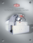
42031, 42044 CP2/CP3
Washer-Extractors
PELLERIN MILNOR CORPORATION
POST OFFICE BOX 400, KENNER, LOUISIANA 70063-0400, U.S.A.
Please Read
About the Manual Identifying Information on the Cover
The front cover displays pertinent identifying information for this manual. Most important, are
the published manual number (part number) /ECN (date code). Generally, when a replacement
manual is furnished, it will have the same published manual number, but the latest available ECN.
This provides the user with the latest information applicable to his machine. Similarly all
documents comprising the manual will be the latest available as of the date the manual was
printed, even though older ECN dates for those documents may be listed in the table of
contents.
When communicating with the Milnor factory regarding this manual, please also provide the
other identifying information shown on the cover, including the publishing system, access date,
and whether the document ECN’s are the latest available or exact.
References to Yellow Troubleshooting Pages
This manual may contain references to “yellow pages.” Although the pages containing
troubleshooting procedures are no longer printed on yellow paper, troubleshooting instructions, if
any, will be contained in the easily located “Troubleshooting” chapter or section. See the table of
contents.
Trademarks of Pellerin Milnor Corporation
The following, some of which may be used in this manual, are trademarks of Pellerin Milnor
Corporation:
Ampsaver®
Autolint®
Auto-Purge®
Autovac
CBW®
Dye-Extractor®
Dyextractor®
E-P Express®
E-P OneTouch®
E-P Plus®
Gear Guardian®
Hands-Off®
Hydro-Cushion®
Mildata®
Milnet®
Milnor®
Miltrac
Miltron
Comments and Suggestions
Help us to improve this manual by sending your comments to:
Pellerin Milnor Corporation
Attn: Technical Publications
P. O. Box 400
Kenner, LA 70063-0400
Fax: (504) 469-1849
Staph-Guard®
System 4®
System 7®
Totaltrol®
Table of Contents
for MPP42SUPAE/2006153A
42031, 42044 CP2/CP3 Washer-Extractors
Page
Description
Document/ECN
1
3
4
5
Approval and Procurement Record
Warranty
How to Order Parts
Safety—Divided Cylinder and Staph-Guard™
Washer-Extractors
BMP74009/81213
11
Section 1: Lubrication
12
13
Lubrication Chart
Lubrication Instructions
15
16
17
18
19
20
21
23
Clutch, Brake and Drive
Removal, Installation & Setting Main Bearings & Seals
Removal, Installation & Setting Main Bearings & Seals
Removal, Installation & Setting Main Bearings & Seals
Removal, Installation & Setting Main Bearings & Seals
BMP701483/71172A
BMP701450/73047A
BMP700246/70023A
BMP701227/78337A
BMP701227R/78337A
BMP701228/78337A
BMP701228R/78337A
Section 4: Steam and Air
27
Section 5: Installation
Installation
Installation
Installation
Installation
Air Mount Installation - Shipboard 42"
Parts List - Air Mount Installation, Shipboard 42"
How to Adjust Water Level
MSSM0130AE/9313AV
BMP800020/96066V
BMP720107/72352A
BMP720107R/77412A
BMP720108/72352A
BMP720108R/72352A
BMP770129/87316C
BMP770129R/88432A
BMP701110/71172B
Section 6: Fuse and Wire Sizes
36
37
Recommended Fuse and Wire Sizes
Recommended Fuse and Wire Sizes
39
Section 7: Dimensional Drawings
41
42
43
44
BIUUUS27/20051111
Section 3: Main Bearings and Seals
Servicing Air Cylinders
Burket Steam Valve
35
BMP720097R/72332A
Section 2: Drive Components
24
26
28
29
30
31
32
33
34
BMP720097/92732A
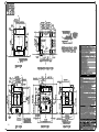
Dimensional Drawing - 42044NP2/CP2 Washer Extractor
Dimensional Drawing - 42044NP2, CP2 Options
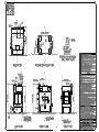
Dimensional Drawing - 42031NP2/CP2 Washer-Extractor
Dimensional Drawing - 42031NP2/CP2 Options
BMP700564/83141A
BMP700564R/83141A
BD4244NPAE/97112D
BD4244NPAB/2002384D
BD4231NPAE/97112D
BD4231NPAB/93292D
1
2
3(//(5,10,/125&25325$7,21
/,0,7('67$1'$5':$55$17<
We warrant to the original purchaser that MILNOR machines including electronic
hardware/software (hereafter referred to as “equipment”), will be free from defects in material
and workmanship for a period of one year from the date of shipment from our factory with no
operating hour limitation. This warranty is contingent upon the equipment being installed,
operated and serviced as specified in the operating manual supplied with the equipment, and
operated under normal conditions by competent operators.
Providing we receive written notification of a warranted defect within 30 days of its discovery,
we will – at our option – repair or replace the defective part or parts, FOB our factory. We
retain the right to require inspection of the parts claimed defective in our factory prior to
repairing or replacing same. We will not be responsible, or in any way liable, for unauthorized
repairs or service to our equipment, and this warranty shall be void if the equipment is repaired
or altered in any way without MILNOR’s written consent.
Parts which require routine replacement due to normal wear – such as gaskets, contact points,
brake and clutch linings and similar parts – are not covered by this warranty, nor are parts
damaged by exposure to weather or to chemicals.
We reserve the right to make changes in the design and/or construction of our equipment
(including purchased components) without obligation to change any equipment previously
supplied.
ANY SALE OR FURNISHING OF ANY EQUIPMENT BY MILNOR IS MADE ONLY UPON
THE EXPRESS UNDERSTANDING THAT MILNOR MAKES NO EXPRESSED OR IMPLIED
WARRANTIES OF MERCHANTABILITY OR FITNESS FOR ANY PARTICULAR USE OR
PURPOSE. MILNOR WILL NOT BE RESPONSIBLE FOR ANY COSTS OR DAMAGES
ACTUALLY INCURRED OR REQUIRED AS A RESULT OF: THE FAILURE OF ANY OTHER
PERSON OR ENTITY TO PERFORM ITS RESPONSIBILITIES, FIRE OR OTHER HAZARD,
ACCIDENT, IMPROPER STORAGE, MISUSE, NEGLECT, POWER OR ENVIRONMENTAL
CONTROL MALFUNCTIONS, DAMAGE FROM LIQUIDS, OR ANY OTHER CAUSE BEYOND
THE NORMAL RANGE OF USE. REGARDLESS OF HOW CAUSED, IN NO EVENT SHALL
MILNOR BE LIABLE FOR SPECIAL, INDIRECT, PUNITIVE, LIQUIDATED, OR
CONSEQUENTIAL COSTS OR DAMAGES, OR ANY COSTS OR DAMAGES WHATSOEVER
WHICH EXCEED THE PRICE PAID TO MILNOR FOR THE EQUIPMENT IT SELLS OR
FURNISHES.
WE NEITHER ASSUME, NOR AUTHORIZE ANY EMPLOYEE OR OTHER PERSON TO
ASSUME FOR US, ANY OTHER RESPONSIBILITY AND/OR LIABILITY IN CONNECTION
WITH THE SALE OR FURNISHING OF OUR EQUIPMENT TO ANY BUYER.
BMP720097
92732A
3
How to order repair parts
Repair parts may be ordered either from the authorized dealer who sold you this
machine, or directly from the MILNOR factory. In most cases, your dealer will
have these parts in stock.
When ordering parts, please be sure to give us the following information:
1. Model and serial number of the machine for which the parts are required
2.
Part number
3. Name of the part
4. Quantity needed
5. Method of shipment desired
6. In correspondence regarding motors or electrical controls, please include all
nameplate data, including wiring diagram number and the make or
manufacturer of the motor or controls.
All parts will be shipped C.O.D. transportation charges collect only.
Please read this manual
It is strongly recommended that you read the installation and operating manual
before attempting to install or operate your machine. We suggest that this manual
be kept in your business office so that it will not become lost.
PELLERIN MILNOR CORPORATION
32%2;.(11(5/$86$
FAX: Administration 504/468-9307, Engineering 504/469-1849, Service 504/469-9777
BMP720097R
72332A
4
BIUUUS27 (Published) Book specs- Dates: 20051111 / 20051111 / 20060323 Lang: ENG01 Applic: HDU
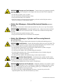
Safety—Divided Cylinder and Staph-Guard™ Washer-Extractors
1.
General Safety Requirements—Vital Information for
Management Personnel [Document BIUUUS04]
Incorrect installation, neglected preventive maintenance, abuse, and/or improper repairs, or
changes to the machine can cause unsafe operation and personal injuries, such as multiple
fractures, amputations, or death. The owner or his selected representative (owner/user) is
responsible for understanding and ensuring the proper operation and maintenance of the machine.
The owner/user must familiarize himself with the contents of all machine instruction manuals.
The owner/user should direct any questions about these instructions to a Milnor® dealer or the
Milnor® Service department.
Most regulatory authorities (including OSHA in the USA and CE in Europe) hold the owner/user
ultimately responsible for maintaining a safe working environment. Therefore, the owner/user
must do or ensure the following:
• recognize all foreseeable safety hazards within his facility and take actions to protect his
personnel, equipment, and facility;
• work equipment is suitable, properly adapted, can be used without risks to health or safety,
and is adequately maintained;
• where specific hazards are likely to be involved, access to the equipment is restricted to those
employees given the task of using it;
• only specifically designated workers carry out repairs, modifications, maintenance, or
servicing;
• information, instruction, and training is provided;
• workers and/or their representatives are consulted.
Work equipment must comply with the requirements listed below. The owner/user must verify
that installation and maintenance of equipment is performed in such a way as to support these
requirements:
• control devices must be visible, identifiable, and marked; be located outside dangerous zones;
and not give rise to a hazard due to unintentional operation;
• control systems must be safe and breakdown/damage must not result in danger;
• work equipment is to be stabilized;
• protection against rupture or disintegration of work equipment;
• guarding, to prevent access to danger zones or to stop movements of dangerous parts before
the danger zones are reached. Guards to be robust; not give rise to any additional hazards; not
be easily removed or rendered inoperative; situated at a sufficient distance from the danger
zone; not restrict view of operating cycle; allow fitting, replacing, or maintenance by
restricting access to relevant area and without removal of guard/protection device;
• suitable lighting for working and maintenance areas;
• maintenance to be possible when work equipment is shut down. If not possible, then
protection measures to be carried out outside danger zones;
• work equipment must be appropriate for preventing the risk of fire or overheating; discharges
of gas, dust, liquid, vapor, other substances; explosion of the equipment or substances in it.
PELLERIN MILNOR CORPORATION
5
Safety—Divided Cylinder and Staph-Guard™ Washer-Extractors
1.1.
Laundry Facility—Provide a supporting floor that is strong and rigid enough to support–with
a reasonable safety factor and without undue or objectionable deflection–the weight of the fully
loaded machine and the forces transmitted by it during operation. Provide sufficient clearance for
machine movement. Provide any safety guards, fences, restraints, devices, and verbal and/or
posted restrictions necessary to prevent personnel, machines, or other moving machinery from
accessing the machine or its path. Provide adequate ventilation to carry away heat and vapors.
Ensure service connections to installed machines meet local and national safety standards,
especially regarding the electrical disconnect (see the National Electric Code). Prominently post
safety information, including signs showing the source of electrical disconnect.
1.2.
Personnel—Inform personnel about hazard avoidance and the importance of care and
common sense. Provide personnel with the safety and operating instructions that apply to them.
Verify that personnel use proper safety and operating procedures. Verify that personnel
understand and abide by the warnings on the machine and precautions in the instruction manuals.
1.3.
Safety Devices—Ensure that no one eliminates or disables any safety device on the machine
or in the facility. Do not allow machine to be used with any missing guard, cover, panel or door.
Service any failing or malfunctioning device before operating the machine.
1.4.
Hazard Information—Important information on hazards is provided on the machine safety
placards, in the Safety Guide, and throughout the other machine manuals. Placards must be kept
clean so that the information is not obscured. They must be replaced immediately if lost or
damaged. The Safety Guide and other machine manuals must be available at all times to
the appropriate personnel. See the machine service manual for safety placard part numbers.
Contact the Milnor Parts department for replacement placards or manuals.
1.5.
2.
Maintenance—Ensure the machine is inspected and serviced in accordance with the norms of
good practice and with the preventive maintenance schedule. Replace belts, pulleys, brake
shoes/disks, clutch plates/tires, rollers, seals, alignment guides, etc. before they are severely
worn. Immediately investigate any evidence of impending failure and make needed repairs (e.g.,
cylinder, shell, or frame cracks; drive components such as motors, gear boxes, bearings, etc.,
whining, grinding, smoking, or becoming abnormally hot; bending or cracking of cylinder, shell,
frame, etc.; leaking seals, hoses, valves, etc.) Do not permit service or maintenance by
unqualified personnel.
Safety Alert Messages—Internal Electrical and Mechanical
Hazards [Document BIUUUS11]
The following are instructions about hazards inside the machine and in electrical enclosures.
WARNING 1 : Electrocution and Electrical Burn Hazards—Contact with electric power
can kill or seriously injure you. Electric power is present inside the cabinetry unless the main
machine power disconnect is off.
• Do not unlock or open electric box doors.
• Do not remove guards, covers, or panels.
• Do not reach into the machine housing or frame.
• Keep yourself and others off of machine.
• Know the location of the main machine disconnect and use it in an emergency to remove
all electric power from the machine.
PELLERIN MILNOR CORPORATION
6
WARNING 2 : Entangle and Crush Hazards—Contact with moving components normally
isolated by guards, covers, and panels, can entangle and crush your limbs. These components
move automatically.
• Do not remove guards, covers, or panels.
• Do not reach into the machine housing or frame.
• Keep yourself and others off of machine.
• Know the location of all emergency stop switches, pull cords, and/or kick plates and use
them in an emergency to stop machine motion.
3.
Safety Alert Messages—External Mechanical Hazards [Document
BIUUUS12]
The following are instructions about hazards around the front, sides, rear or top of the machine.
WARNING 3 : Crush Hazards—Suspended machines only—Spaces between the shell and
housing can close and crush or pinch your limbs. The shell moves within the housing during
operation.
• Do not reach into the machine housing or frame.
• Keep yourself and others clear of movement areas and paths.
4.
Safety Alert Messages—Cylinder and Processing Hazards
[Document BIUUUS13]
The following are instructions about hazards related to the cylinder and laundering process.
WARNING 4 : Crush Hazards—Contact with the turning cylinder can crush your limbs. The
cylinder will repel any object you try to stop it with, possibly causing the object to strike or stab
you. The turning cylinder is normally isolated by the locked cylinder door.
• Do not attempt to open the door or reach into the cylinder until the cylinder is stopped.
• Do not place any object in the turning cylinder.
• Do not operate the machine with a malfunctioning door interlock.
• Divided cylinder machines only—Keep yourself and others clear of cylinder and goods
during inching or Autospot operation.
• Do not operate the machine with malfunctioning two-hand manual controls.
WARNING 5 : Confined Space Hazards—Confinement in the cylinder can kill or injure
you. Hazards include but are not limited to panic, burns, poisoning, suffocation, heat prostration,
biological contamination, electrocution, and crushing.
• Do not attempt unauthorized servicing, repairs, or modification.
WARNING 6 : Explosion and Fire Hazards—Flammable substances can explode or ignite
in the cylinder, drain trough, or sewer. The machine is designed for washing with water, not any
other solvent. Processing can cause solvent-containing goods to give off flammable vapors.
• Do not use flammable solvents in processing.
• Do not process goods containing flammable substances. Consult with your local fire
department/public safety office and all insurance providers.
PELLERIN MILNOR CORPORATION
7
Safety—Divided Cylinder and Staph-Guard™ Washer-Extractors
5.
5.1.
5.1.1.
Safety Alert Messages—Unsafe Conditions [Document BIUUUS14]
Damage and Malfunction Hazards
Hazards Resulting from Inoperative Safety Devices
DANGER 7 : Entangle and Sever Hazards—Cylinder door interlock—Operating the
machine with a malfunctioning door interlock can permit opening the door when the cylinder is
turning and/or starting the cycle with the door open, exposing the turning cylinder.
• Do not operate the machine with any evidence of damage or malfunction.
WARNING 8 : Multiple Hazards—Operating the machine with an inoperative safety device
can kill or injure personnel, damage or destroy the machine, damage property, and/or void the
warranty.
• Do not tamper with or disable any safety device or operate the machine with a
malfunctioning safety device. Request authorized service.
WARNING 9 : Electrocution and Electrical Burn Hazards—Electric box doors—
Operating the machine with any electric box door unlocked can expose high voltage conductors
inside the box.
• Do not unlock or open electric box doors.
WARNING 10 : Entangle and Crush Hazards—Guards, covers, and panels—Operating
the machine with any guard, cover, or panel removed exposes moving components.
• Do not remove guards, covers, or panels.
5.1.2.
Hazards Resulting from Damaged Mechanical Devices
WARNING 11 : Multiple Hazards—Operating a damaged machine can kill or injure
personnel, further damage or destroy the machine, damage property, and/or void the warranty.
• Do not operate a damaged or malfunctioning machine. Request authorized service.
WARNING 12 : Explosion Hazards—Cylinder—A damaged cylinder can rip apart during
extraction, puncturing the shell and discharging metal fragments at high speed.
• Do not operate the machine with any evidence of damage or malfunction.
WARNING 13 : Explosion Hazards—Inner door latches (divided cylinder machines)—A
damaged or improperly seated latch can cause the inner door to open during operation, damaging
the cylinder and shell. A damaged cylinder can rip apart during extraction, puncturing the shell
and discharging metal fragments at high speed.
• Ensure that the inner door is securely latched when loading and unloading.
• Do not operate the machine with any evidence of damage or malfunction.
WARNING 14 : Explosion Hazards—Clutch and speed switch (multiple motor
machines)—A damaged clutch or speed switch can permit the low speed motor to engage during
extract. This will over-speed the motor and pulleys and can cause them to rip apart, discharging
metal fragments at high speed.
• Stop the machine immediately if any of these conditions occur: • abnormal whining sound
during extract • skidding sound as extract ends • clutches remain engaged or re-engage
during extract
PELLERIN MILNOR CORPORATION
8
5.2.
5.2.1.
Careless Use Hazards
Careless Operation Hazards—Vital Information for Operator Personnel (see also
operator hazards throughout manual)
WARNING 15 : Multiple Hazards—Careless operator actions can kill or injure personnel,
damage or destroy the machine, damage property, and/or void the warranty.
• Do not tamper with or disable any safety device or operate the machine with a
malfunctioning safety device. Request authorized service.
• Do not operate a damaged or malfunctioning machine. Request authorized service.
• Do not attempt unauthorized servicing, repairs, or modification.
• Do not use the machine in any manner contrary to the factory instructions.
• Use the machine only for its customary and intended purpose.
• Understand the consequences of operating manually.
5.2.2.
Careless Servicing Hazards—Vital Information for Service Personnel (see also
service hazards throughout manuals)
WARNING 16 : Electrocution and Electrical Burn Hazards—Contact with electric
power can kill or seriously injure you. Electric power is present inside the cabinetry unless the
main machine power disconnect is off.
• Do not service the machine unless qualified and authorized. You must clearly understand
the hazards and how to avoid them.
• Abide by the current OSHA lockout/tagout standard when lockout/tagout is called for in
the service instructions. Outside the USA, abide by the OSHA standard in the absence of
any other overriding standard.
WARNING 17 : Entangle and Crush Hazards—Contact with moving components
normally isolated by guards, covers, and panels, can entangle and crush your limbs. These
components move automatically.
• Do not service the machine unless qualified and authorized. You must clearly understand
the hazards and how to avoid them.
• Abide by the current OSHA lockout/tagout standard when lockout/tagout is called for in
the service instructions. Outside the USA, abide by the OSHA standard in the absence of
any other overriding standard.
WARNING 18 : Confined Space Hazards—Confinement in the cylinder can kill or injure
you. Hazards include but are not limited to panic, burns, poisoning, suffocation, heat prostration,
biological contamination, electrocution, and crushing.
• Do not enter the cylinder until it has been thoroughly purged, flushed, drained, cooled,
and immobilized.
— End of BIUUUS27 —
PELLERIN MILNOR CORPORATION
9
10
Section
Lubrication
11
1
12
13
14
Section
Drive Components
15
2
SECTION 8
CLUTCH, BRAKE AND DRIVE
The clutch is essentially a tubeless tire which may be automatically inflated by air. The tire is mounted
on the reducer shaft and nests into a hollow portion of the main drive pulley which is much like an
automobile brake drum. When the tire is inflated, it expands outwardly and grips the inside of the
drum, thus transmitting power from the gear reducer to the washer shaft. When the air is released, the
tire automatically reverts to its normal size, thus becoming disengaged from the main pulley so that the
machine may be run at Extract Speed without over speeding the helical gear unit. During washing and
inching, the cylinder is driven by the Wash Speed motor through the gear reducer and the clutch, while
the Drain Speed motor and the Extract motor merely coast. As soon as the drain Valve opens, the
Wash Speed motor is shut off and coasts with the Extract motor, while the Drain Speed motor drives
the cylinder through the reducer and clutch. During extraction, both the Wash Speed and Drain Speed
motors are shut off, the clutch disengaged, and the Extract motor drives the cylinder through the
Extract motor “V” belt drive. At the expiration of extraction, the Extract motor is shut off, the brake
applied, and either the Drain Speed or Wash Speed motor (depending upon whether the Drain Valve is
open or closed) starts and runs idle while the brake decelerates the machine. When the machine has
slowed down sufficiently to actuate the centrifugal switch, the brake is automatically released, and the
clutch engaged thus returning the machine to the Wash cycle or Drain Speed.
Air controlled by a solenoid valve and the MILTROL is admitted to the clutch through a drilled hole in
the center of the reducer shaft. The air is prevented from entering the reducer housing itself by a
mechanical end face seal which is in the air inlet on the reducer. The reducer is additionally fitted with
a vented fill plug to prevent build up of air pressure in the housing should the mechanical seal fail.
Absolutely no clutch adjustment is necessary in the field. Except for the fact that the air supplied to
the unit must be reasonable free of oil and moisture, there is otherwise no field clutch maintenance
necessary.
NOTE: IF THE MACHINE SHOULD MAKE A LOUD SCREECHING SOUND LIKE SKIDDING
AUTOMOBILE TIRES DURING DECELERATION FROM EXTRACT SPEED TO WASH SPEED,
TURN MASTER SWITCH TO “OFF” IMMEDIATELY AND SEE TROUBLE SHOOTING
SECTION.
A quick release valve permits instant clutch release by providing a large area “short circuit” exhaust
connection near the clutch. The quick release valve is necessary for the clutch used on washerextractors, and is furnished as original equipment.
The brake band is applied to a portion of the outside of the Combination-Brake drum pulley. The
brake is normally on, and braking pressure is supplied by the action of springs inside the brake air
cylinder. The brake is released when air is admitted to the top of the air cylinder. Brake may be
readily adjusted to compensate for wear by adjusting nuts on the air cylinder stem.
Litho in U.S.A.
1M 246/70023
16
Section
Main Bearings and Seals
17
3
18
19
20
21
22
Section
Steam and Air
23
4
MSSM0130AE/9313AV
SERVICING AIR CYLINDERS
È
4. Loosen nuts on threaded rods evenly, permitting cylinder heads to separate. Use only a few turns on one nut
before moving to the other one. Continue until springs have no tension.
This is the general procedure for rebuilding an air cylinder using a Milnor® furnished repair kit, once the air
cylinder has been removed from the machine. See the specific air cylinder and major assembly parts drawing(s) for
component identification and removal/replacement information.
Maintenance procedures require:
•
•
Two threaded rods and nuts, twice the length of the tie bolts.
The appropriate repair kit.
EXPLOSION HAZARD—Spring tension can cause air cylinder to burst apart
with great force during dissassembly. You can be struck by air cylinder parts.
☞ Follow maintenance instructions carefully.
☞ Wear eye protection.
NOTE: Use a new locknut when re-assembling air cylinder (see the appropriate parts drawing).
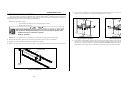
1. Replace two diagonally opposite tie bolts with threaded rods and nuts as shown in FIGURE 1.
2. Tighten nuts on the threaded rods until they contact the air cylinder.
3. Remove the other two tie bolts and the nuts, washers, clips, and actuators from the external end of piston stem.
Tie bolt
Threaded rod
Piston
stem
ÎFIGURE 1 (MSSM0130AE)
ÎUsing Threaded Rods
24
ÎFIGURE 2 (MSSM0130AE)
ÎCorrect Piston Cup Shape
ÎFIGURE 3 (MSSM0130AE)
ÎDistorted Piston Cup Shape
5. Note position and orientation of piston cup(s), washers, and springs. Replace worn parts, then reassemble in
reverse order. Tighten locknut until it is just barely possible to turn the piston cup and washer assembly on
the stem. Correct piston cup shape is shown in FIGURE 2. DO NOT overtighten, as this causes the piston
cup to deform to the shape shown in FIGURE 3 and may cause piston to bind in cylinder.
MSSM0130AE/9313AV (1 of 1 )
SERVICING AIR CYLINDERS
È
4. Loosen nuts on threaded rods evenly, permitting cylinder heads to separate. Use only a few turns on one nut
before moving to the other one. Continue until springs have no tension.
This is the general procedure for rebuilding an air cylinder using a Milnor® furnished repair kit, once the air
cylinder has been removed from the machine. See the specific air cylinder and major assembly parts drawing(s) for
component identification and removal/replacement information.
Maintenance procedures require:
•
•
Two threaded rods and nuts, twice the length of the tie bolts.
The appropriate repair kit.
EXPLOSION HAZARD—Spring tension can cause air cylinder to burst apart
with great force during dissassembly. You can be struck by air cylinder parts.
☞ Follow maintenance instructions carefully.
☞ Wear eye protection.
NOTE: Use a new locknut when re-assembling air cylinder (see the appropriate parts drawing).
1. Replace two diagonally opposite tie bolts with threaded rods and nuts as shown in FIGURE 1.
2. Tighten nuts on the threaded rods until they contact the air cylinder.
3. Remove the other two tie bolts and the nuts, washers, clips, and actuators from the external end of piston stem.
ÎFIGURE 2 (MSSM0130AE)
ÎCorrect Piston Cup Shape
ÎFIGURE 3 (MSSM0130AE)
ÎDistorted Piston Cup Shape
5. Note position and orientation of piston cup(s), washers, and springs. Replace worn parts, then reassemble in
reverse order. Tighten locknut until it is just barely possible to turn the piston cup and washer assembly on
the stem. Correct piston cup shape is shown in FIGURE 2. DO NOT overtighten, as this causes the piston
cup to deform to the shape shown in FIGURE 3 and may cause piston to bind in cylinder.
Tie bolt
Threaded rod
Piston
stem
ÎFIGURE 1 (MSSM0130AE)
ÎUsing Threaded Rods
25
26
R
3
P. O. Box 400, Kenner, LA 70063-0400
Pellerin Milnor Corporation
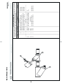
Burket Steam Valve
2
1
BMP800020/96066V (1 of 1)
Parts List—Burket Steam Valve
Item
Part Number
Description
Comments
96D0011ER1
96D0011ER2
96D0011ER3
X
Y
Z
REPAIR KIT MULLER 1.25 VALVE #554
ACTUATOR HOUSING FOR BURKET #251
02Z REPAIR KIT 1.25" STEAM VALVE
02Z REPAIRKIT 3/4" STEAM VALVE
KIT FOR 001B
KIT FOR 001B
KIT FOR 001B
KIT FOR 001A
1
1
2
3
3
all
all
all
all
all
51T060
51T030
96H018
96D0011E
96D0009E
01Z Y-STRAINER 1+1/4" CAST IRON
01Z Y-STRAINER 3/4" CAST IRON
NEEDLE VALVE
08Z 1/25"NPT N/C STEAMVAL ANGLEBODY
03Z 3/4"NPT N/C STEAMVAL ANGLE BODY
USED WITH 001B
USED WITH 001A
1-1/4"
3/4"
-------------------------------------------------------------------COMPONENTS------------------------------------------------------------------
96D0009ER1
W
---------------------------------------------------------------------ASSEMBLIES------------------------------------------------------------------
. Used In
Find the correct assembly first, then find the needed components. The item letters (A, B, C, etc.) assigned to
assemblies are referred to in the "Used In" column to identify which components belong to an assembly. The item
numbers (1, 2, 3, etc.) assigned to components relate the parts list to the illustration.
Litho in U.S.A.
BMP800020/96066V
(Sheet 1 of 1)
Section
Installation
27
5
28
29
30
31
32
33
34
Section
Fuse and Wire Sizes
35
6
36
37
38
Section
Dimensional Drawings
39
7
40
41
42
43
44