1
IST-2000-25187
Deliverable D4.3
Evaluation of Phase I Field Trial
Project Number:
IST-2000-25187
Project Title:
TORRENT
Deliverable Security*:
PU
CEC Deliverable Number:
D4.3
Contractual Date of Delivery to the CEC:
30.11.2002
TORRENT
Actual Date of Delivery to the CEC:
Title of Deliverable:
Evaluation of Phase I Field Trial
Work package contributing to the Deliverable:
WP4
Type of Deliverable**:
R
Author:
Isabel Borges
Contributors:
M.Potts, G.Grun (MCLab); R. Tolstra
(tesion); W. Payer (UST); I. Mountzouris
(Intracom); V. Apostolopoulou, P.
Karapanagiotis (TEMAGON); A.
Costoloni (Flextel); T. Konstali (Telenor);
P. Rolo (PTIN)
* Security:
PU – Public, PP - Restricted to other programme participants (including the Commission Services)
RE - Restricted to a group specified by the consortium (including the Commission Services)
CO - Confidential, only for members of the consortium (including the Commission Services)
** Type:
R - Report, P - Prototype, D - Demonstrator, O - Other
Abstract:
This deliverable is concerned with the validation of the key functionalities of the first phase of
the TORRENT test-bed, covering the customer premises, access network and the local access
point. It will provide important input to phase two of TORRENT, especially the field trials. The
significance of the results to exploitation will also feature here.
Keywords: Field trial, functionalities, testing, network management, evaluation
IST-2000-25187
PUBLIC
Page 1 of 77
IST-2000-25187
Deliverable D4.3
Evaluation of Phase I Field Trial
TORRENT
© This Deliverable is Copyright of the
TORRENT Consortium
IST-2000-25187
whose partners are:
Queen Mary and Westfield College (UK)
Portugal Telecom Inovação SA (Portugal)
Estto-Hellenic PTT Consulting Organisation SA (Greece)
Telenor AS (Norway)
tesion Communikationsnetze Südwest GmbH (Germany)
Flextel SPA (Italy)
Intracom SA (Greece)
MCLAB GmbH (Switzerland)
Universität Stuttgart (Germany)
Waterford Institute of Technology (Ireland)
IST-2000-25187
PUBLIC
Page 2 of 77
IST-2000-25187
Deliverable D4.3
Evaluation of Phase I Field Trial
TORRENT
Executive Summary
This deliverable presents the results of the evaluation performed on the TORRENT system. The
TORRENT system is composed of distinct sub-systems either in hardware or software. Several
of these parts have been tested and the first available functionalities have been evaluated.
Chapter one and chapter two will give an introduction and will present the main objectives of
this deliverable.
The third chapter focuses on the description and configuration of each of the foreseen field trial,
also accommodating the introduction of IPv6. The approach used is based on the split into two
testing phases. The first one is running in a controlled environment (at MultiComLab premises),
performing tests to the first functionalities of the system, detecting problems and providing
inputs in order to enhance ans improve the system. This information will be fed back to WP2
(Home Network and Local Access Point) and WP3 (Service and Resource Management). In the
second phase, four field trials will demonstrate enhanced features considering not only other
access technologies but also security and QoS aspects. These field trials will run in
infrastructures deployed namely at TEMAGON, PTIN, Telenor, and connecting MCLab and the
University of Stuttgart through tesion. The results coming from this phase will feed into WP2,
WP3, and WP5 (Exploitation and Dissemination).
The fourth chapter describes the set-up of the MCLab test-bed, the results of the tests and the
validation criteria that were taken into account to analyse the results of the tests [1].
In chapter five, “Analysis of Results”, the analysis of the results considering the validation
criteria and the expected result is presented.
Finally, in chapter six, the main conclusions resulting from this work and a set of
recommendations are stated.
IST-2000-25187
PUBLIC
Page 3 of 77
IST-2000-25187
Deliverable D4.3
Evaluation of Phase I Field Trial
TORRENT
Table of Contents
Executive Summary ........................................................................................................ 3
1 Introduction .................................................................................................................. 6
2 Objectives ..................................................................................................................... 6
3 Description of Field Trials ........................................................................................... 7
3.1 Phase 1 field trials .................................................................................7
3.1.1 TORRENT integration sessions ..........................................................7
3.1.2 MultiComLab field trial.....................................................................7
3.2 Phase 2 field trials .................................................................................9
3.2.1 TEMAGON .....................................................................................9
3.2.2 PTIN........................................................................................... 12
3.2.3 Telenor ....................................................................................... 14
Existing infrastructure ......................................................................................... 14
Phase 1 test system using Torrent equipment ...................................................... 15
User equipment ................................................................................................... 16
User terminals ..................................................................................................... 16
In-house servers................................................................................................... 17
3.2.4 Interconnection field trials – test-bed Hardware for the tesion/IND/MCLab
field trial ..................................................................................... 17
Core networks ..................................................................................................... 17
Initial test set-up .................................................................................................. 20
New test set-up using IPv6 .................................................................................. 22
4 MCLab TORRENT testing .......................................................................................... 24
4.1 Residential Gateway - RG...................................................................... 24
4.2 ISDN – Intracom netMod ...................................................................... 29
4.2.1 ADSL – Intracom jetSpeed 500....................................................... 29
4.2.2 RG API........................................................................................ 30
4.2.3 TCP/IP-based............................................................................... 31
4.2.4 SNMP-based ................................................................................ 32
4.3 Test set-up ......................................................................................... 33
4.4 Results of the tests .............................................................................. 50
5 Analysis of Results .................................................................................................... 59
6 Conclusions and Recommendations ....................................................................... 61
7 Annex 1 ....................................................................................................................... 63
7.1 Address Structure of the TORRENT test equipment in the MCLab................. 63
7.2 LAP - Configuration info for extern access to the LAP in MCLAB .................. 63
7.3 ADSL Environment Activation .................................................................... 65
7.4 TTCP and NETPERF............................................................................... 65
7.5 Measurements..................................................................................... 69
7.5.1 Throughput IPB ............................................................................ 70
7.5.2 Throughput Core Blade.................................................................. 72
7.5.3 Throughput Core Blade – RG1 ........................................................ 74
IST-2000-25187
PUBLIC
Page 4 of 77
IST-2000-25187
Deliverable D4.3
Evaluation of Phase I Field Trial
TORRENT
Abbreviations ................................................................................................................ 76
8 References.................................................................................................................. 77
IST-2000-25187
PUBLIC
Page 5 of 77
IST-2000-25187
Deliverable D4.3
Evaluation of Phase I Field Trial
TORRENT
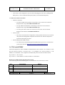
1 Introduction
The first deliverable of this WP, D4.1 “Metrics for Field Trials” has established a first description
of field trials and its phased approach. An iterative methodology to perform the tests was
presented, and a set of tests have been designed to validate the features that have been defined in
WP 1, “Architectural Framework” and the metrics associated with each test have been identified.
The second deliverable, D4.2, “Definition of Phase One Field Trials” has presented the
organization of the tests, with a special focus on the Phase I trial, that were implemented at
MCLab premises comprising all the integration activities and first series of tests. The impact of
field trials on exploitation plans has been presented.
Phase I field trial is an essential field trial whose importance has to do not only with the
verification of the correctness of the concept but also has to identify the enhancements that should
be introduced to be demonstrated in Phase II. This feedback is being continuously provided since
the involved partners are connected to this field trial testing their modules and correcting its
behaviours.
2 Objectives
The main objective of this deliverable is to present the first results of the tests that were specified
in deliverable D4.2, “Definition of Phase I Field Trials” [2]. These results are extremely
important since they will allow to obtain feedback from the integration of several modules
developed by several partners and this will allow that the TORRENT concept can be validated.
Other sub-objectives are:
o
Verification of first functionalities of the LAP and RG, according with the tests defined
o
Verification of integration of ADSL into the LAP
o
Providing an analysis of the results and give some recommendations for phase II field
trials.
IST-2000-25187
PUBLIC
Page 6 of 77
Deliverable D4.3
Evaluation of Phase I Field Trial
IST-2000-25187
TORRENT
3 Description of Field Trials
3.1 Phase 1 field trials
3.1.1
TORRENT integration sessions
Since July till November 2002 several work sessions at MCLab have been carried out to integrate
the modules produced by different partners working at WP2 and WP3. Some results coming so
far from those working sessions are presented in Annex 1 of this deliverable.
3.1.2
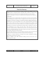
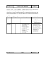
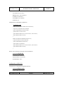
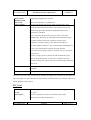
MultiComLab field trial
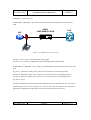
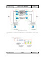
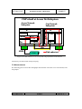
In Figure 1 the MCLab field trial setup is shown.
RG management,
monitoring
and control
LAP management
monitoring
and control
alternative
access to user
PSTN
dial up access
ISP
messages for signalling , control,
management
ISDN
SO
A
D
S
L
Ethernet
M
O
D
E
M
Internet
CORE 1
(Internet)
MPLS
CORE 2
D
S
L
A
M
VoD
server
CORE 3
ATM
RG
LAP
ISDN
ADSL
MODEM
ISDN
Passive
Filter
DSLAM
Figure 1: MCLab field trial
IST-2000-25187
PUBLIC
Page 7 of 77
IST-2000-25187
Deliverable D4.3
Evaluation of Phase I Field Trial
TORRENT
The experiments foreseen for validating the system integration (HW and SW, in the LAP and
RG) as well as the requirements of the field trial were:
•
Residential Gateway with ADSL modem functionality (either internal or external).
•
Local Access Point with ADSL DSLAM integrated and having at least 2 external
interfaces, representing links to separate core networks.
•
Basic User Interface, probably Web browser menu based, for service selection
•
Installation, operation and maintenance instructions from the RG and LAP developers,
concerning the usage of their equipment. This refers mainly to:
•
o
Installation procedures.
o
Configuration procedures.
User Commands (for example: service selection, setting user profiles, requesting
charging information, equipment status checking).
•
Operator Commands for querying the system.
•
Diagnostic messages and their meaning.
IST-2000-25187
PUBLIC
Page 8 of 77
Deliverable D4.3
Evaluation of Phase I Field Trial
IST-2000-25187
TORRENT
3.2 Phase 2 field trials
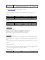
3.2.1
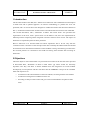
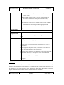
TEMAGON
TEMAGON, formerly OTEC, will aim for testing this system when integrated in a full ADSL
scenario. The ability to be connected to different ISPs will be investigated and the behaviour of
the full system will be compared with the “only” ADSL scenario. There are two test
configurations according to Figures 1 and 2.
RG
ADSL
LINE SIMULATOR
LAP
SD
DATAX
PORT A
SD RD
ONLINE
PORT B
SD RD
A
B
iZ 9200
BWD
PORT SEL
-
+
EN TER
DISC DATA
SPLITTER
Figure 2: TEMAGON Physical layer tests
IST-2000-25187
PUBLIC
Page 9 of 77
IST-2000-25187
Deliverable D4.3
Evaluation of Phase I Field Trial
TORRENT
Figure 3: Routing and application layer tests
In the Figure 2 (IPv4 case) the measurements will be performed as stated. The Voice Gateway,
MCU and Gatekeeper will be used. A stream server will be used for real time applications and a
VoD for non-real time applications.
In the IPv6 case the configuration will be as follows:
Figure 4: Ipv6 configuration
IST-2000-25187
PUBLIC
Page 10 of 77
Deliverable D4.3
Evaluation of Phase I Field Trial
IST-2000-25187
TORRENT
TEMAGON – Field Trial Tests
1. Test Case 4 – F4_Tests (1) - Ability of internetworking/communication between RG and
LAP
ADSL
LINE SIMULATOR
RG
LAP
SD
DATAX
PORT A
PORT B
SD RD
SD RD
ONLINE
A
B
iZ 9200
BWD
PORT SEL
-
+
ENTER
DISC DATA
SPLITTER
Figure 5: Configuration for case 4 tests
F4_Test9 - Service Class versus Maximum Loop Length
F4_Test10 - Co-working of ADSL/POTS and Uninterrupted POTS functionality
2. Test Case 4 – F4_Tests
(2) - Ability of internetworking/communication between RG and
LAP
F4_Test11 – Measures of delay, jitter, packet Loss on interactive real time applications
F4_Test12 - Measures of delay, jitter, packet Loss on non-interactive real time applications
F4_Test13 - Measures of delay, jitter, packet Loss on interactive burst transfer applications
F4_Test14 – Pings
The above measurements will be performed as defined for IPv4. In the IPv6 case, the tests will be
performed only with web server and ftp server. This is due to the fact that there are currently no
applications compatible with IPv6 protocol for video streaming and VoD services.
IST-2000-25187
PUBLIC
Page 11 of 77
Deliverable D4.3
Evaluation of Phase I Field Trial
IST-2000-25187
3.2.2
TORRENT
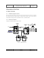
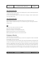
PTIN
Figure 5 shows the configuration of the PTIN field trial.
Class 4/5 switch
HFC
PSTN
Backbone IP/ATM
network
ISDN phone
ISDN
NT
LAP
ATM
switch
RG
Router
ADSL
ISDN phone
Figure 6: PTIN field trial
PTIN field trial will test the TORRENT equipment over a cable TV network. One possibility is to
test one customer in the ADSL network and another customer on the HFC network. Both
customers will be connected to the same LAP and will have a narrowband ISDN network. The
residential customers will use both home networks, wired and wireless (IEEE 802.11b). For the
core network ATM and IP will be used and access to PSTN can be made available.
The main differentiation aspect is concerned with the use of different access networks connected
to the same LAP and the LAP communication with both T-RGs. This will validate the behaviour
of the LAP when confronted with several access technologies, allowing a convergence of access
networks.
IST-2000-25187
PUBLIC
Page 12 of 77
Deliverable D4.3
Evaluation of Phase I Field Trial
IST-2000-25187
TORRENT
The proposed scenario will allow to some extent testing the ability of the Residential Gateway to
choose the access network according to user requirements and network characteristics. For this,
the software could choose between the broadband network, cable or ADSL, and a narrowband
network – ISDN.
Services like FTP, web browsing and eventually video streaming will be available for the
experiments.
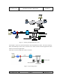
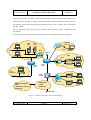
For IPv6 testing the available scenario at PTIN premises is illustrated in the following figure.
IPv6
DNS
Wireless
802.11b
IPv6
Web
Access
Point
Ethernet
Home
Agent
IPv6
6bone
HFC
IPv6
Cable modem
Cisco
3600
CMTS
Cisco
7500
IPv4
Ethernet
ATM
Switch
ADSL
modem
DSLAM
Future European
IPv6
(Euro6IX network)
backbone
Portuguese
ATM
backbone
ADSL
modem
TEN-155
Figure 7: Available IPv6 network for PTIN field trial
IST-2000-25187
PUBLIC
Page 13 of 77
Deliverable D4.3
Evaluation of Phase I Field Trial
IST-2000-25187
3.2.3
TORRENT
Telenor
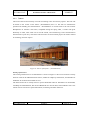
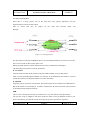
This trial will be focused mainly on home networking issues and security aspects. The trial will
be based on the “house of the future” (Fremtidshuset) that is a lab with an infrastructure
optimised for building new demonstrators. “Fremtidshuset” is located close to the new Telenor
Headquarters at Fornebu. The house, completed during the spring 2001, is made with great
flexibility in mind, inner walls can be moved around, and restructuring of the communication
infrastructure is quite easy. The house will be used for several research projects in Telenor related
to technology and user aspects.
Figure 8:“house of the future” (Fremtidshuset)
Existing infrastructure
The existing infrastructure in “Fremtidshuset” is shown in Figure 9. The access network is mainly
based on cable for broadband Internet and TV, ISDN for telephony and Internet, and Satellite for
additional TV channels and related services.
The internal network is mainly based on special dedicated cable for distribution of multimedia,
100 Mbps switched Ethernet, WLAN and BlueTooth are used for data, and LonWorks and 1-wire
microLAN are used for low speed automation, monitoring and alarm functions.
IST-2000-25187
PUBLIC
Page 14 of 77
IST-2000-25187
Deliverable D4.3
Evaluation of Phase I Field Trial
TORRENT
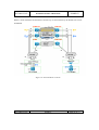
Figure 9: Existing infrastructure in “Fremtidshuset”
The LAP should be configured to support two T-RGs, communicating over an Ethernet interface.
The LAP also uses an Ethernet interface for communication to the core networks, which in this
case is the internal Ethernet in “Fremtidshuset”. Both the LAP and the T-RGs also are supplied
with ISDN interfaces. Also Ethernet interfaces are used for the in house networks. Both LAP and
T-RG are implemented on a PC platform running Linux.
Phase 1 test system using Torrent equipment
Figure 9 shows a modified architecture for Torrent tests in “Fremtidshuset”. The Torrent system
is connected to the internal Ethernet inside the firewall. The internal network thus simulates the
core network. Some terminals, gateways and servers are moved from the existing networks to the
Torrent internal networks, thus simulating a user environment
IST-2000-25187
PUBLIC
Page 15 of 77
Deliverable D4.3
Evaluation of Phase I Field Trial
IST-2000-25187
TORRENT
Figure 10: Configuration of Telenor field trial
User equipment
Each T-RG will at least be connected to:
•
One user terminal
•
One server
•
One gateway to another in house network.
User terminals
The user terminals will be PCs running a MS Windows client (Win98 or Win2k).
IST-2000-25187
PUBLIC
Page 16 of 77
IST-2000-25187
Deliverable D4.3
Evaluation of Phase I Field Trial
TORRENT
The terminals will use dynamic IP address. Internet access and file and print sharing should be
possible for all terminals connected. These terminals and functions performed by these terminals
should normally be visible only at the T-RG internal networks.
In-house servers
Several server types will be used (WEB camera server, micro-WEB server, MS Windows server
(Win NT4 or Win2k) running MS Internet Information Server). These servers will normally use
static IP addresses. Internet, file and print sharing should be possible at the T-RG internal
networks. At least some functions on one server should be accessible from the outside networks,
i.e. WWW pages that might contain real time dynamic information. Also peer-to-peer
applications like Napster should be applicable. These servers will also act as gateways to other inhouse networks like LonWorks and 1-wire micro LAN.
3.2.4
Interconnection field trials – test-bed Hardware for the tesion/IND/MCLab field
trial
Core networks
The LAPs will be based in Stuttgart (IND) and Basel (MCLab) and there will be dedicated
accesses to different types of networks. This enables the LAP to select and access the most
suitable network depending on the requested application.
Since tesion is a full-service provider, there is a choice between voice (switch), data and Internet
services. The network technologies integrated are ATM, IP, MPLS, SDH and DWDM.
For testing the LAP features and interconnectivity the choice was made to use the MPLS and
SDH core networks.
This way the following interconnections will be realised:
•
IP over MPLS
•
IP tunnelled or via VPN
•
SDH
IST-2000-25187
PUBLIC
Page 17 of 77
IST-2000-25187
Deliverable D4.3
Evaluation of Phase I Field Trial
TORRENT
Figure 11a tesion)) Backbone (partially)
The LAPs in Stuttgart and Basel will have an SDH core-network, a MPLS network and a
TORRENT VPN or tunnel, which enables the laboratories to test a QoS core scenario.
Since the access points are located away from the laboratories, an E1 for each type of network
will be made available in both, Basel and Stuttgart, in order to connect the LAP’s interfaces to the
access points of the networks.
The capacity of an E1 link (2048 kb/s) for each type of network will be sufficient for the tests.
Since these tests are performed over a live network with numerous users connected, this is the
safest way to give the LAPs access to the core networks.
IST-2000-25187
PUBLIC
Page 18 of 77
IST-2000-25187
Deliverable D4.3
Evaluation of Phase I Field Trial
TORRENT
Figure 11b: Connection of Basel and Stuttgart through tesion network with 3 technologies
The main features of this field trial are to show and to test the capabilities of RG and LAP
connected to different types of networks. Also the interconnectivity between LAPs will be tested.
The aspects and features, which can be tested here, are:
•
Ability of the RG to be connected to different networks
•
Ability of interworking between RG and LAP and LAP-to-LAP
•
Ability of the user to select the appropriate network (QoS)
•
Ability to provide system status information to the RG and LAP
•
Ability to suit network operator requirements.
IST-2000-25187
PUBLIC
Page 19 of 77
IST-2000-25187
Deliverable D4.3
Evaluation of Phase I Field Trial
TORRENT
Initial test set-up
The figure below shows the basic layout of the test configuration between MCLab/Basel and
IND/Stuttgart, which enables the LAP to have access to different core networks.
Figure 12: Initial test set-up
This results in a network routing as shown below, enabling the testing using IPv4, providing the
flexibility required if it would be needed.
IST-2000-25187
PUBLIC
Page 20 of 77
IST-2000-25187
Deliverable D4.3
Evaluation of Phase I Field Trial
TORRENT
Figure 13:IPv4 tesion set-up
The configuration as seen from the individual laboratories can be simplified as shown in Figure
14.
Figure 14: Configuration at laboratories
IST-2000-25187
PUBLIC
Page 21 of 77
Deliverable D4.3
Evaluation of Phase I Field Trial
IST-2000-25187
TORRENT
New test set-up using IPv6
Since this is a living project, one of the items that were gaining importance was the
implementation of IPv6 instead of IPv4.
This
of
course
had
also
an
impact
on
the
field
trial
between
Basel
and
Stuttgart.
Figure 15: Set-up for IPv6
For the purpose of using the TORRENT IPv6 over tesion MPLS backbone, tesion have received a
beta-version of SW for their routers from Cisco.
During the field trial there will be dedicated core routers in Karlsruhe and Stuttgart.
The following interconnections will be performed:
IP over MPLS
The beta-software takes the IPv6 packet and puts a MPLS header on top of this packet.
Then it is transferred through the MPLS core network. At the destination this header is removed
and the IPv6 packet is transported further to its final destination.
IP tunnelled
Originally (IPv4) an IP VPN was planned. The disadvantage for the available IPv6 MPLS SW is
that the IP V6PN is not available yet. In order to simulate this, the interconnection will be realised
by tunnelling this through the network.
SDH
This is in fact a leased line and can be considered as a very fast network with optimal QoS.
The way the set-up is adapted to suit these needs also offers a kind of fallback scenario to use
IPv4 in the unlikely case that IPv6 LAP interconnectivity doesn’t perform as expected.
IST-2000-25187
PUBLIC
Page 22 of 77
IST-2000-25187
Deliverable D4.3
Evaluation of Phase I Field Trial
TORRENT
Within a short timeframe the alternative connectivity as shown below by the dotted lines can be
established.
Figure 16: IPv4 and IPv6 scenarios
IST-2000-25187
PUBLIC
Page 23 of 77
Deliverable D4.3
Evaluation of Phase I Field Trial
IST-2000-25187
TORRENT
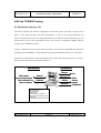
4 MCLab TORRENT testing
4.1 Residential Gateway - RG
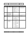
This section specifies the network configuration for the RG system. The latter is being used in
phase 1 trials. More precisely, the basic functionality, as well as, the relevant hardware and
software infrastructure of RGs, are being implemented in accordance to deliverable D2.1 [4]. This
infrastructure will host the agent-based service and resource management (SRM) software
package of the TORRENT system.
In phase 1 MCLab trials two (2) PC-based type RGs is used. This PC-based RG runs the Linux
operating system (RedHad 7.3, USAGI SNAP usagi-linux24-s20020527 based on 2.4.18 kernel).
Following, a configuration for RG regarding the WAN and LAN network interfaces, as well as,
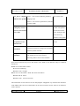
the RG system description is presented in Figure 17.
WAN Interfaces
ADSL modem
(Intracom jetSpeed 500)
Ethernet
10/100 BaseT
ISDN modem/NT box
(Intracom netMod)
LAN Interfaces
T
T--RG
RG
USB/serial
port
Ethernet
LAN
10/100 BaseT
IEEE 802.11b
WLAN
USB port
Serial port
General
purpose
Configuration
• HP VECTRA VEI7
• HP VECTRA VEI7
• Celeron 400 MHz
• Celeron 400 MHz
• 256MB RAM
• 256MB RAM
• 2x 3Com EtherLink 10/100 PCI
• 2x 3Com EtherLink 10/100 PCI
• 3Com AirConnect Wireless LAN PCI
• 3Com AirConnect Wireless LAN PCI
• RedHat 7.3
• RedHat 7.3
• USAGI SNAP kernel based on 2.4.18
• USAGI SNAP kernel based on 2.4.18
Figure 17. RG system and interfaces (phase 1)
IST-2000-25187
PUBLIC
Page 24 of 77
Deliverable D4.3
Evaluation of Phase I Field Trial
IST-2000-25187
TORRENT
The access network is based on ADSL for broadband Internet services and ISDN for plain
telephony service (including the support of the emergency calls service, as well).
Common basis for the basic RG functions is the support of a high-performance TCP/IP stack. RG
supports dual IP stack (IPv4 & IPv6) functionality. The basic RG functions, described in detail in
D2.1 [4], are summarized in the following table.
Functions
IPv4
IPv6
Description
Instructions
−
System
access
−
Routing and
forwarding
−
DHCP −
RADVD −
−
−
−
−
IST-2000-25187
IP routing and forwarding
between WAN and inhome network
Broadband internet
connection sharing
Dual IP stack
Dynamic / Automatic
configuration
Stateless
autoconfiguration
mechanisms
PUBLIC
−
Root user
− Login: root
− Password: icom-rg
Torrent user
− Login: torrent
− Password: torrent-rg
The DHCP and RADVD
daemons are running
automatically on system
boot. The range of the
allocated IPv4 and IPv6
addresses are specified on
the additional
configuration files.
(/etc/dhcpd.conf,
/etc/radvd.conf)
Page 25 of 77
Deliverable D4.3
Evaluation of Phase I Field Trial
IST-2000-25187
Functions
System and
network
management
IPv4
−
−
−
−
−
IPv6
SNMP / MIB II
T-RG MIB
T-RG status
indication tool
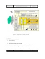
Web-based
management (IPv4)
Command line
(Serial, Telnet)
Description
−
−
−
IST-2000-25187
TORRENT
Ucd SNMP package
§ Compiled from
sources to support the
AgentX protocol for
the extension of the
master SNMP Agent
functionality (T-RG
MIB)
Web-based management
§ Webmin
Ø Web-based
interface for
system, network
and user
management
Ø Web browser
(Java enabled for
specific modules)
Ø Customisable
Ø Support T-RG
functions (e.g.
DHCP, PPP, etc.)
§ JetSpeed 500
Ø Web-based
interface to
configure
INTRACOM
jetSpeed 500
(ADSL modem)
Instructions
−
SNMP daemon
(/usr/local/sbin/snmpd)
runs on system boot.
−
http://193.72.156.82:10000
(T-RG1)
http://193.72.156.83:10000
(T-RG2)
−
−
−
−
http://192.168.0.1 (J500 TRG1)
http://192.168.1.1 (J500 TRG2)
/root/RG_GUI/Project1
(start the T-RG status
indication tool. You have
to check the LAP_addr file
for the correct LAP IP
address)
T-RG status indication
tool
§ Standalone tool
(developed with
Borland Kylix 2.0)
§ Kylix runtime
§ System and network
management
§ Features
Ø Interfaces list
Ø Routing info
Ø Connection
tracking info
Ø Connection status
with LAP
Ø Controls fail over
functionality
PUBLIC
Page 26 of 77
Deliverable D4.3
Evaluation of Phase I Field Trial
IST-2000-25187
Functions
Failover
IPv4
−
IPv6
Intracom’s custom
application
Description
−
−
−
−
−
Wireless
−
−
Wireless device
driver
T-RG access point
−
−
−
Bridging
−
One home
subnetwork
(Ethernet, wireless)
−
−
Layer 2
support
−
−
−
PPP
−
VPN
support
−
−
−
IPsec
−
QoS support
−
CBQ
−
Linux
Traffic
Control
CBQ
−
−
IST-2000-25187
TORRENT
Daemon implementation
Checks periodically the
ADSL connectivity with
LAP
Signals the ADSL link
failure (T-RG status
indication tool)
Activate (dial) ISDN
connection
Switch back to ADSL
connection after link is up
again
Wireless device driver
(HostAP driver)
Wireless NIC operates in
Access Point mode
T-RG is an 802.11b
Access Point for the
Home Network
Bridge connects two or
more different physical
interfaces together to
form one large (logical)
interface
Home interfaces
(ethernet-eth1, wireless
wlan0) could be bridged
into a virtual network
interface (br0)
One home subnetwork
Configure PPP for
Intracom’s netMod ISDN
NT
Support USB & RS-232
interfaces
IPv6 enabled
IPsec support (USAGI
kernel configuration)
IPsec trials with preshared
and RSA keys (D4.2)
Layer 3 QoS support:
Packet
scheduling/filtering
mechanism (CBQ-based)
Example for bandwidth
PUBLIC
Instructions
−
Using the RG status
indication tool.
−
HostAp driver is loaded
automatically on system
boot.
Additional entries in
/etc/rc.local
−
−
/root/bridge (this script file
bridges the home
interfaces (eth1, wlan0)
into a virtual network
interface (br0)
−
pppd call isp (start PPP
connection based on the
files being configured on
/etc/ppp)
−
/root/ipsecstart,
/root/ipsecRSAstart (these
script files enables the
Ipsec support)
/etc/rc.d/init.d/bwdiv start
(start the CBQ example)
−
Page 27 of 77
Deliverable D4.3
Evaluation of Phase I Field Trial
IST-2000-25187
Functions
DNS
IPv4
−
IPv6
Primary DNS Server
Description
−
−
−
−
−
Server
functionality
−
−
WWW
server
Services &
Tools
−
−
File, print and
application server
Proxy-based server
(Squid package –
IPv6 enabled)
Apache (IPv6
enabled)
ssh, telnet, ftp,
netperf, ttcp
−
−
IPv6
connectivity
with LAP
−
−
Full IPv6
connectivity
IPv6 in IPv4
tunnelling
−
−
IST-2000-25187
TORRENT
division using CBQ
DNS server (IPv4/IPv6)
Bind installed from
distribution
Standard Bind system
configuration with IPv6
support
Configuration IPv6 zones
& entries
Primary DNS server for
the Home Network
Instructions
−
Primary DNS server for
the home network is
loaded on system boot.
−
Apache server is loaded on
system boot
Extended Internet services
daemon (xinetd-ipv6)
§ Enabled services: ssh,
ftp, telnet
Network performance
measurements tools
§ netperf, ttcp, ttcp6
Full IPv6 connectivity
−
§ jetSpeed 500 and
LAP must be
configured to support
“bridged” service
IPv6 in IPv4 tunnelling
§ Configure T-RG as a
tunnel end-point
(client)
§ LAP will be
configured as the
second tunnel endpoint (server)
§ LAP must provide
info for the tunnelling
PUBLIC
T-RG is configured as a
tunnel end-point (client).
Page 28 of 77
IST-2000-25187
Deliverable D4.3
Evaluation of Phase I Field Trial
TORRENT
4.2 ISDN – Intracom netMod
Network access products have been developed by INTRACOM in order to provide high quality
ISDN services and high-speed Internet access, allowing also existing analogue devices to work
over an ISDN connection. netMod is one of the basic network access products, which is used for
connecting RG to ISDN access network.
The basic features of netMod are the following:
•
ISDN Basic Access provision by an S-bus (offering connection to up to eight ISDN
terminals) and two POTS interfaces.
•
One serial dataport for high-speed data communication through an RS-232 and/or a USB
connection.
•
Network Management System capability.
•
Emergency Operation Mode (in case of main power failure at the subscriber premises,
one ISDN or POTS terminal, selected by the user, is remotely powered from the ISDN
exchange via the U-line).
4.2.1
ADSL – Intracom jetSpeed 500
Intracom’s jetSpeed 500, which is used for connecting T-RG to ADSL access network, is a
compact external ADSL network terminal device with both USB and Ethernet interfaces,
therefore ensuring connectivity to all types of new and legacy computers. Furthermore, jetSpeed
500 encompass functionalities (e.g., DHCP client and server, NAT and RIP), which effectively
transform the unit from a simple bridge into a powerful router.
Some basic features of the jetSpeed 500 are the following:
•
Operating mode ADSL Full rate (Downstream: 32 to 8032 kb/s – Upstream: 32 to 864
kb/s) or ADSL lite rate (Downstream: 32 to 1536 kb/s – Upstream: 32 to 512 kb/s)
•
Simultaneous lifeline voice-telephone support
•
USB and/or Ethernet connectivity
IST-2000-25187
PUBLIC
Page 29 of 77
IST-2000-25187
Deliverable D4.3
Evaluation of Phase I Field Trial
TORRENT
•
Plug and play installation
•
Web-based easy configuration and local management
•
Additional security to the “always on” ADSL connection by a “Lock” button that
prevents unauthorized access when jetSpeed 500 is not in use.
4.2.2
RG API
This section specifies the RG API through which the SRM software controls the low-level
network element functions. The RG API provides to the RG and LAP management agents all the
necessary network and system information. This consists of configuration, operational and
statistical data.
The implementation of the RG API has been based on a hybrid approach. More precisely, the RG
API provides the following two approaches for the RG system management.
•
TCP/IP-based
•
SNMP-based
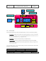
The architecture of the RG API is depicted in the following figure.
IST-2000-25187
PUBLIC
Page 30 of 77
Deliverable D4.3
Evaluation of Phase I Field Trial
IST-2000-25187
TORRENT
Agent running on T-RG
or on a Remote System
Service
Agents
Java lib
Service Access Point
Using the RG Daemon
T-RG C-Lib
TCP/IP
Service Access Point
Using the SNMP Agent
User Space
T-RG Daemon
Direct
Access
SNMP
Linux SNMP
SNMP Manager
SNMP
SNMP
Agent
Service Agents
MIB II
T-RG
MIB
LAP
SNMP Agent extension for TRG
Parameter
s to MIB
mapper
Parameter
Retriever
T-RG
configuration
files
/proc
filesystem
NETLINK API
Kernel Space
Network
Protocol
Stack
Network
Device Driver
Linux Traffic
Control
Figure 18. RG API architecture
4.2.3
TCP/IP-based
The TCP/IP-based approach of the RG API implementation, consists on the following modules:
−
RG Daemon: handles all the requests from the RG API library. In order to return back
the results of the function calls it uses either the SNMP protocol or the direct access to
the specific RG information (e.g. configuration files)
−
RG C library: provides the API functionality to the SRM software.
−
RG Java library: provides an alternative API functionality (Java-based) to the SRM
software. This library operates with the already implemented C library by using the Java
Native Interface (JNI).
The implemented functions of the C and Java library are shown in the table below, while the full
description is specified in D2.2 [5].
Functions
C-API
set_forwarding
IST-2000-25187
Description
Java-API
setforwarding
PUBLIC
Set (enable/disable) IPv4
Page 31 of 77
IST-2000-25187
Deliverable D4.3
Evaluation of Phase I Field Trial
get_forwarding
get_rxpackets
getforwarding
getrxpackets
get_systemdescr
getsystemdescr
get_lapconnstatus
getlapconnstatus
set_isdnconnstatus
setisdnconnstatus
get_iflist
getiflist
get_conntrack
get_v4route
get_v6route
get_adsldevinfo
get_adslwanstatus
getconntrack
getv4route
getv6route
getadsldevinfo
getadslwanstatus
get_adsletherstatus
getadsletherstatus
get_adsllinestatus
execcommand
getadsllinestatus
execcom
4.2.4
TORRENT
forwarding
Read the IPv4 forwarding value
Get the number of received
packets on RG interface 3 (SNMP)
Get the system description of RG
(SNMP)
Get the status of the RG-LAP
connection
Set (enable/disable) the ISDN
connection
Get the list of interfaces available
on the RG
Get the connection tracking info
Get the IPv4 routing table
Get the IPv6 routing table
Get the ADSL modem device info
Get the ADSL modem WAN
interface status
Get the ADSL modem Ethernet
interface status
Get the ADSL modem line status
Execute system command to RG
SNMP-based
The second approach of the RG API implementation has been based on the standard SNMP
protocol. The SNMP agent running at the RG side has been implemented using the UCD -SNMP
package. In addition, the functionality of the SNMP agent will be extended by the necessary agent
function, in order to support RG specific data (e.g., wireless interface). This extension (RG MIB)
provides all the necessary objects that will be useful for the LAP and the Service Agents.
For each SNMP operation on the RG MIB objects, the SNMP agent invokes functions in the
software module that implements the SNMP Agent extension for RG (RG Agent). The RG Agent
consists of two backend processing modules, which retrieve or set configuration
parameters/values and map them to RG MIB objects, while sources of these parameters include
the following:
•
Various configuration files for the RG functions (e.g. conf files of DHCP, or RADVD
server)
•
/proc filesystem, being a pseudo-filesystem and acting as an interface to kernel data
structures. A variety of network information and data is available in the /proc/net/
directory, containing interface statistics, protocol statistics, routing and arp tables etc.
IST-2000-25187
PUBLIC
Page 32 of 77
IST-2000-25187
•
Deliverable D4.3
Evaluation of Phase I Field Trial
TORRENT
Through the Linux NETLINK API. In this case, the RG Agent opens a netlink socket to
the kernel and requests proper parameters for the SNMP operation. This kind of
communication is very useful in cases that the requested data can be retrieved directly
form the device drivers of the network adapters or from specific kernel modules like
netfilter and traffic control.
The definition of the RG MIB in terms of detailed specification of the managed objects should be
based on the requirements of RG and LAP management agents. Managed objects are accessed via
a virtual information store, called the Management Information Base or MIB. Objects in the MIB
are defined, using the subset of Abstract Syntax Notation One (ASN.1). In particular, each object
has a name, syntax, and an encoding. The name is an object identifier, an administratively
assigned name, which specifies an object type. The object type together with an object instance
serves to uniquely identify a specific instantiation of the object.
The standard MIB II and the T-RG MIB are being used by the RG API. The first one is involved
in the following areas:
•
System
•
Interfaces
•
Network protocols
•
SNMP
The second one consists of the MIB II standard extensions in the following areas:
•
System Management
Interfaces Management
4.3 Test set-up
IST-2000-25187
PUBLIC
Page 33 of 77
Deliverable D4.3
Evaluation of Phase I Field Trial
IST-2000-25187
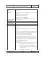
TORRENT
In Figure the MCLab configuration of the phase I field trial 19 is shown.
LAN
Internet
eth2 192.168.201.1
NAT
home-pc1
(Linux)
eth0 dhcp
eth1 192.168.200.1
eth0 193.72.156.88
eth0:1 193.72.156.82 (remote RG1)
eth0:2 193.72.156.83 (remote RG1)
eth0:3 193.72.156.85 (rem. J500 RG1)
eth0:4 193.72.156.86 (rem. J500 RG1) eth1 193.72.156.193
wlan0 192.168.20.1
eth1:1 192.168.200.2
Cisco
7206
10.0.0.10
RG
1
J500
192.168.0.1
Fujitsu
CO card 0
eth0 193.72.156.81
(extern access)
Itf0 (atm0-ipb)
10.0.0.1
Itf1 (atm1-ipb)
10.0.1.1
Management
Subsystem
ipb0
192.168.5.1
(flextel01)
eth1 193.72.156.225
wlan0 192.168.21.1
eth1:1 192.168.201.2
eth0
192.168.0.10
eth1
193.72.156.84
First
Access
Network
Subsystem
10.0.1.10
Core
Network
Subsystem
ipb0
192.168.5.2
(flextel02)
RG
2
J500
192.168.1.1
eth0
192.168.1.10
Fujitsu
CO card 1
Second
Access
Network
Subsystem
ipb0
192.168.5.3
(flextel03)
ipb0
192.168.5.4
(flextel04)
Figure 19: Configuration of MCLab field trial
Network configuration
The network set-up contains several parts that are described in this section:
•The
LAP including the Flextel system with 2 Fujitsu ADSL Modems and 2 interface for the
core network (eth0 on the management subsystem and eth1 on the core network subsystem)
•RG1
including a Linux PC with 2 Ethernet interfaces, one wireless LAN interface and the
ADSL Modem J500.
•RG2
is the same system as RG1
•Home PC1
•Home
•One
is representing a home user’s machine with web browser based on Linux
PC2 is representing a home user’s machine with web browser based on Windows 2000.
Core network is represented by the LAN infrastructure of MCLab, which allow connecting
to local services as web ftp mail DNS or access to the Internet.
IST-2000-25187
PUBLIC
Page 34 of 77
IST-2000-25187
•Remote
Deliverable D4.3
Evaluation of Phase I Field Trial
TORRENT
access to the RGs for remote testing and support using bypass links that work
independent of the LAP-to-RG links.
The LAP configuration currently in use at MCLab is different to the final configuration.
•The
Core Network Subsystem is used for special tests by WP3.
•The
Management Subsystem takes over the functionality of the Core Network Subsystem but
only with one core link.
•IPv6
is not available on all parts which prevents using IPv6 at all with this set-up.
LAP (Flextel System)
The LAP contains the following parts:
•
Management Subsystem (flextel01)
•
First Access Network Subsystem (flextel02) plus Fujitsu ADSL modem
•
Core Network Subsystem (flextel03)
•
Second Access Network Subsystem (flextel04) plus Fujitsu ADSL modem
The Management Subsystem is connected to the core network and over the ADSL links to the
RGs using ATM links.
Hardware & operating system
Each Subsystem is a one-processor module consisting of:
•Pentium
•Linux
III 800MHz, 256MB Memory, Hard disk 15GB, 10/100 Ethernet port
Redhat 7.2, Kernel 2.4.7-10custom
Access to the Subsystems
login: root, password: flextel
login: torrent, password: basel
IST-2000-25187
PUBLIC
Page 35 of 77
Deliverable D4.3
Evaluation of Phase I Field Trial
IST-2000-25187
TORRENT
From remote you can log in to the Management Subsystem using ssh as root (or torrent). From
there all other subsystems are accessible with Telnet using the login torrent and changing with the
“su” command to root.
Start up ATM
Ethernet connectivity is given by starting up the system. To bring up the ATM links the following
steps have to be done:
•On
the Management Subsystem as root:
•“/root/ADSL/atmadmin
•On
start” (brings up the ATM interfaces atm0 and atm1)
the First and Second Access Network Subsystems:
•/root/SWITCH/aal5swd
Configuring IP addresses
Only the IP addresses for the external access must me configured at torrent01:
/etc/sysconfig/network-scripts/ifcfg-eth0
DEVICE=eth0
ONBOOT=yes
BOOTPROTO=static
IPADDR=193.72.156.81
NETMASK=255.255.255.224
GATEWAY=193.72.156.94
Setting the routes
There is no routing daemon running on the LAP. Some additional routing entries has to be done
manually:
Routing to the networks at RG1
route add -net 192.168.0.0 gw 10.0.0.10 metric 1 netmask 255.255.255.0
route add -net 193.72.156.192 gw 10.0.0.10 metric 1 netmask 255.255.255.224
Routing to the networks at RG2
route add -net 192.168.1.0 gw 10.0.1.10 metric 1 netmask 255.255.255.0
route add -net 193.72.156.224 gw 10.0.1.10 metric 1 netmask 255.255.255.224
Using the command “netstat -nr” the routing table should look like:
IST-2000-25187
PUBLIC
Page 36 of 77
Deliverable D4.3
Evaluation of Phase I Field Trial
IST-2000-25187
Destination
193.72.156.64
193.72.156.224
193.72.156.192
192.168.5.0
10.0.0.0
10.0.1.0
192.168.1.0
192.168.0.0
127.0.0.0
0.0.0.0
Gateway
0.0.0.0
10.0.1.10
10.0.0.10
0.0.0.0
0.0.0.0
0.0.0.0
10.0.1.10
10.0.0.10
0.0.0.0
93.72.156.94
Genmask
255.255.255.224
255.255.255.224
255.255.255.224
255.255.255.0
255.255.255.0
255.255.255.0
255.255.255.0
255.255.255.0
255.0.0.0
0.0.0.0
Flags
U
UG
UG
U
U
U
UG
UG
U
UG
MSS
40
40
40
40
40
40
40
40
40
40
TORRENT
Window
0
0
0
0
0
0
0
0
0
0
rtt Iface
0 eth0
0 atm1
0 atm0
0 0 ipb0
0 atm0
0 atm1
0 atm1
0 atm0
0 lo
0 eth0
RG 1 & 2
Hardware:
Each RG System contains:
•HP
VECTRA VEI7, Celeron 400Mhz, 256MB RAM, 2x 3Com Etherlink 10/100 PCI, 3Com
AirConnect Wireless LAN PCI
•ADSL
Modem Intracom JetSpeed 500
•Hardware
•Software
•ADSL
revision JETBOARD 1.0
revision 1.1.1.0
Firmware revision R3_8_124
•Configuration
type JetSpeed 500
•ISDN
NT Intracom netMod
•Linux
Redhat 7.3, Kernel 2.4.18usagi-20020527
Access to the RGs:
For remote administration:
•RG1
with ssh to 193.72.156.82
•RG2
with ssh to 193.72.156.83
Access over LAP and ADSL:
•RG1
with ssh to 193.72.156.193
•RG2
with ssh to 193.72.156.225
IST-2000-25187
PUBLIC
Page 37 of 77
IST-2000-25187
Deliverable D4.3
Evaluation of Phase I Field Trial
TORRENT
login: root, pw: icom-rg
login torrent, pw torrent-rg
Configuration of RG1 (PC)
Configuration of hostname and default gateway:
/etc/sysconfig/network
HOSTNAME=rg1.mclab.ch
GATEWAY=192.168.0.1
Configuration of the Ethernet interface connected to the ADSL modems:
/etc/sysconfig/network-scripts/ifcfg-eth0
DEVICE=eth0
BOOTPROTO=static
BROADCAST=192.168.0.255
IPADDR=192.168.0.10
NETMASK=255.255.255.0
NETWORK=192.168.0.0
ONBOOT=yes
Configuration of the Ethernet interface connected to the home-LAN:
/etc/sysconfig/network-scripts/ifcfg-eth1
DEVICE=eth1
BOOTPROTO=static
NETMASK=255.255.255.224
BROADCAST=193.72.156.223
IPADDR=193.72.156.193
NETWORK=193.72.156.192
ONBOOT=yes
Configuration of the Ethernet interface connected to the NAT box for remote administration:
/etc/sysconfig/network-scripts/ifcfg-eth1:1
DEVICE=eth1:1
BOOTPROTO=static
IST-2000-25187
PUBLIC
Page 38 of 77
IST-2000-25187
Deliverable D4.3
Evaluation of Phase I Field Trial
TORRENT
NETMASK=255.255.255.0
BROADCAST=192.168.200.255
IPADDR=192.168.200.2
NETWORK=192.168.200.0
ONBOOT=yes
Configuration of the dhcpd ip addresses:
/etc/dhcpd.conf
subnet 193.72.156.192 netmask 255.255.255.224 {
range 193.72.156.200 193.72.156.220;
option subnet-mask 255.255.255.224;
option routers 193.72.156.193;
option domain-name-servers 193.72.156.10, 193.72.156.13;
option domain-name "test.net";
}
subnet 192.168.20.0 netmask 255.255.255.0 {
range 192.168.20.10 192.168.20.250;
option subnet-mask 255.255.255.0;
option routers 192.168.20.1;
option domain-name-servers 193.72.156.10, 193.72.156.13;
option domain-name "test.net";
}
Set the active interfaces (only eth1 will be used here):
/etc/sysconfig/dhcpd:
# Command line options here
#DHCPDARGS="eth1 wlan0”
DHCPDARGS="eth1"
Configuration of RG2 (PC)
Configuration of hostname and default gateway:
/etc/sysconfig/network:
HOSTNAME=rg2.mclab.ch
IST-2000-25187
PUBLIC
Page 39 of 77
IST-2000-25187
Deliverable D4.3
Evaluation of Phase I Field Trial
TORRENT
GATEWAY=192.168.1.1
Configuration of the Ethernet interface connected to the ADSL modems:
/etc/sysconfig/network-scripts/ifcfg-eth0
DEVICE=eth0
BOOTPROTO=static
BROADCAST=192.168.1.255
IPADDR=192.168.1.10
NETMASK=255.255.255.0
NETWORK=192.168.1.0
ONBOOT=yes
Configuration of the Ethernet interface connected to the home-LAN:
/etc/sysconfig/network-scripts/ifcfg-eth1
DEVICE=eth1
BOOTPROTO=static
NETMASK=255.255.255.224
BROADCAST=193.72.156.255
IPADDR=193.72.156.225
NETWORK=193.72.156.224
ONBOOT=yes
Configuration of the Ethernet interface connected to the NAT box for remote administration:
/etc/sysconfig/network-scripts/ifcfg-eth1:1
DEVICE=eth1:1
BOOTPROTO=static
NETMASK=255.255.255.0
BROADCAST=192.168.201.255
IPADDR=192.168.201.2
NETWORK=192.168.201.0
ONBOOT=yes
Configuration of the dhcpd ip addresses:
/etc/dhcpd.conf
IST-2000-25187
PUBLIC
Page 40 of 77
Deliverable D4.3
Evaluation of Phase I Field Trial
IST-2000-25187
TORRENT
subnet 193.72.156.224 netmask 255.255.255.224 {
range 193.72.156.228 193.72.156.250;
option subnet-mask 255.255.255.224;
option routers 193.72.156.225;
option domain-name-servers 193.72.156.10, 193.72.156.13;
option domain-name "test.net";
}
subnet 192.168.20.0 netmask 255.255.255.0 {
range 192.168.20.10 192.168.20.250;
option subnet-mask 255.255.255.0;
option routers 192.168.20.1;
option domain-name-servers 193.72.156.10, 193.72.156.13;
option domain-name "test.net";
}
Set the active interfaces (only eth1 will be used here):
/etc/sysconfig/dhcpd:
# Command line options here
#DHCPDARGS="eth1 wlan0”
DHCPDARGS="eth1"
ADSL modems RG1 & RG2
The ADSL modems are configurable with a web browser.
The modems are configured with private IP addresses.
Login: admin
Password: admin
Accessible under:
Modem of RG1:
•http://192.168.0.1
(only local)
•http://193.72.156.83
(only remote using the NAT box)
Modem of RG2:
•http://192.168.1.1
IST-2000-25187
(only local)
PUBLIC
Page 41 of 77
Deliverable D4.3
Evaluation of Phase I Field Trial
IST-2000-25187
•http://193.72.156.84
TORRENT
(only remote using the NAT box)
Follow the menu “CONFIGURATION”, “IP routes - RIP” and enter the 2 routing entries.
For RG1:
Destination
0.0.0.0
193.72.156.192
192.168.200.0
Gateway
10.0.0.1
192.168.0.10
192.168.0.10
Netmask
0.0.0.0
255.255.255.224
255.255.255.0
Cost
Gateway
10.0.1.1
192.168.1.10
192.168.1.10
Netmask
0.0.0.0
255.255.255.224
255.255.255.0
Cost
Timeout
1
1
1
0
0
0
For RG2:
Destination
0.0.0.0
193.72.156.224
192.168.201.0
Timeout
1
1
1
0
0
0
The home PCs
There are 2 PCs connected.
•Home
PC 1: Pentium II 400MHz, Linux Mandrake 9.0 connected to RG1
•Home
PC 2: Pentium III 800MHz, Windows 2000 connected to RG2.
Both are getting the network configuration dynamically using DHCP.
The NAT box
The NAT box allows the remote access to RG1 and RG2 without using any connections between
LAP and RGs. This gives the opportunity to administrate the RGs also when the ADSL links are
down.
The box changes destination and source addresses from the core network site to local subnet
addresses.
The system is built with:
•PC
486 33MHz, 20Mbyte RAM (min. 12MByte), 3 Ethernet cards NE2000, Floppy Firewall
2.0.4 from: Zelow Consulting,Oslo, www.zelow.no/floppyfw.
Configuration files:
IST-2000-25187
PUBLIC
Page 42 of 77
IST-2000-25187
Deliverable D4.3
Evaluation of Phase I Field Trial
TORRENT
The file “config” defines interfaces and IP addresses.
config
# TORRENT MCLab parameters:
OUTSIDE_IP=193.72.156.88
OUTSIDE_IP1=193.72.156.82
OUTSIDE_IP2=193.72.156.83
OUTSIDE_IP3=193.72.156.85
OUTSIDE_IP3=193.72.156.86
OUTSIDE_DEV=eth0
OUTSIDE_DEV1=eth0:1
OUTSIDE_DEV2=eth0:2
OUTSIDE_DEV3=eth0:3
OUTSIDE_DEV4=eth0:4
OUTSIDE_NETMASK=255.255.255.224
OUTSIDE_NETWORK=193.72.156.64
OUTSIDE_BROADCAST=193.72.156.95
INSIDE_IP=192.168.200.1
INSIDE_DEV=eth1
INSIDE_NETWORK=192.168.200.0
INSIDE_NETMASK=255.255.255.0
INSIDE_BROADCAST=192.168.200.255
INSIDE_IP1=192.168.201.1
INSIDE_DEV1=eth2
INSIDE_NETWORK1=192.168.201.0
INSIDE_NETMASK1=255.255.255.0
INSIDE_BROADCAST1=192.168.201.255
DEFAULT_GATEWAY=193.72.156.94
NAME_SERVER_IP1=193.72.156.10
NAME_SERVER_IP2=193.72.156.13
HOSTNAME=torrent-gw
IST-2000-25187
PUBLIC
Page 43 of 77
IST-2000-25187
Deliverable D4.3
Evaluation of Phase I Field Trial
TORRENT
DOMAIN=mclab.ch
# untouch parameters of the conf file
DNSMASQ=n
OPEN_SHELL=y
SERIAL_CONSOLE=n
DEBUG_LOG="/dev/tty3"
USE_SYSLOG=n
SYSLOG_FLAGS="-m 360 -O ${DEBUG_LOG}"
SECOND_DEVICE=n
The file “network.ini” starts up the network:
network.ini
#!/bin/sh
. /etc/config
ifconfig lo 127.0.0.1
ifconfig ${INSIDE_DEV} ${INSIDE_IP} netmask ${INSIDE_NETMASK} broadcast
${INSIDE_BROADCAST}
ifconfig ${INSIDE_DEV1} ${INSIDE_IP1} netmask ${INSIDE_NETMASK1}
broadcast ${INSIDE_BROADCAST1}
echo "INSIDE_DEVICE=${INSIDE_DEV}"
echo "INSIDE_IP=${INSIDE_IP}"
> /etc/inside.info
>> /etc/inside.info
echo "INSIDE_NETWORK=${INSIDE_NETWORK}"
echo "INSIDE_NETMASK=${INSIDE_NETMASK}"
>> /etc/inside.info
>> /etc/inside.info
echo "INSIDE_BROADCAST=${INSIDE_BROADCAST}" >> /etc/inside.info
echo "${INSIDE_IP} ${HOSTNAME}.${DOMAIN} ${HOSTNAME}" >> /etc/hosts
# setting up hostname
hostname ${HOSTNAME}
hostname -d ${DOMAIN}
IST-2000-25187
PUBLIC
Page 44 of 77
Deliverable D4.3
Evaluation of Phase I Field Trial
IST-2000-25187
TORRENT
echo "Hostname (fully qualified) set up to `hostname -f`"
if [ ${OUTSIDE_IP} = 'DHCP' ];
then
echo "Booting udhcpc"
echo "OUTSIDE_DEVICE=${OUTSIDE_DEV}" > /etc/outside.info
HARGS=
[ "${HOSTNAME}" != "" ] && HARGS="-H ${HOSTNAME}"
if /bin/udhcpc -n -s /etc/udhcpcrenew.sh ${HARGS} -i ${OUTSIDE_DEV}; then
. /etc/outside.info
else
echo "duh!"
# Or some more useful error handling
fi
else
if [ ${OUTSIDE_IP} = 'EXTERNAL' ];
then
/etc/ext-up.init
else
/bin/ifconfig ${OUTSIDE_DEV} ${OUTSIDE_IP} netmask
${OUTSIDE_NETMASK} broadcast ${OUTSIDE_BROADCAST}
/bin/ifconfig ${OUTSIDE_DEV1} ${OUTSIDE_IP1} netmask
${OUTSIDE_NETMASK}broadcast ${OUTSIDE_BROADCAST}
/bin/ifconfig ${OUTSIDE_DEV2} ${OUTSIDE_IP2} netmask
${OUTSIDE_NETMASK} broadcast ${OUTSIDE_BROADCAST}
/bin/route add default gw ${DEFAULT_GATEWAY} metric 1
echo "Setting up name server (etc/resolv.conf) "
echo "domain ${DOMAIN}" >> /etc/resolv.conf
echo "search ${DOMAIN}" >> /etc/resolv.conf
echo "nameserver ${NAME_SERVER_IP1}" >> /etc/resolv.conf
IST-2000-25187
PUBLIC
Page 45 of 77
IST-2000-25187
Deliverable D4.3
Evaluation of Phase I Field Trial
TORRENT
echo "nameserver ${NAME_SERVER_IP2}" >> /etc/resolv.conf
echo "OUTSIDE_DEVICE=${OUTSIDE_DEV}"
echo "OUTSIDE_IP=${OUTSIDE_IP}"
> /etc/outside.info
>> /etc/outside.info
echo "OUTSIDE_GATEWAY=${DEFAULT_GATEWAY}"
>>
/etc/outside.info
echo "OUTSIDE_NETMASK=${OUTSIDE_NETMASK}"
>> /etc/outside.info
echo "OUTSIDE_NETWORK=${OUTSIDE_NETWORK}"
>> /etc/outside.info
echo "OUTSIDE_BROADCAST=${OUTSIDE_BROADCAST}" >>
/etc/outside.info
echo "Setting up firewall rules: "
/etc/firewall.init
echo
fi # if EXTERNAL
fi
# if DHCP
echo "1" > /proc/sys/net/ipv4/tcp_syncookies
if [ -f /proc/sys/net/ipv4/conf/all/rp_filter ] ; then
echo "Enabling anti spoofing: "
for f in /proc/sys/net/ipv4/conf/*/rp_filter; do
echo -n " $f "
echo 1 > $f
done
else
echo "Anti spoofing is not available, the author of this floppy spoofed, mail
him."
fi
IST-2000-25187
PUBLIC
Page 46 of 77
Deliverable D4.3
Evaluation of Phase I Field Trial
IST-2000-25187
TORRENT
p=`pidof dnsmasq`
if [ "${DHCP_DAEMON}" = "y" ];
then
/etc/udhcpd.conf.sh
udhcpd
[ $p ] || dnsmasq -i ${INSIDE_DEV}
else
if [ "${DNSMASQ}" = "y" ];
then
[ $p ] || dnsmasq -i ${INSIDE_DEV}
fi
fi
The file “firewall.ini” defines only the NAT rules:
firewall.ini
#!/bin/sh
. /etc/config
#
echo "Starting firewall with the following config:"
echo
echo "
Inside
Outside"
echo " Network: ${INSIDE_NETWORK}
echo " Device: ${INSIDE_DEVICE}
echo "IP Address: ${INSIDE_IP}
${OUTSIDE_DEVICE}"
${OUTSIDE_IP}"
echo " Netmask: ${INSIDE_NETMASK}
echo " Broadcast: ${INSIDE_BROADCAST}
echo " Gateway: [None Set]
${OUTSIDE_NETWORK}"
${OUTSIDE_NETMASK}"
${OUTSIDE_BROADCAST}"
${OUTSIDE_GATEWAY}"
echo
IST-2000-25187
PUBLIC
Page 47 of 77
Deliverable D4.3
Evaluation of Phase I Field Trial
IST-2000-25187
TORRENT
iptables -F
iptables -t nat -F
iptables -X
iptables -Z # zero all counters
#
# Not firewalling at all
#
iptables -P INPUT ACCEPT
iptables -P OUTPUT ACCEPT
iptables -P FORWARD ACCEPT
iptables -t nat -A PREROUTING -d 193.72.156.82 -j DNAT --to 192.168.200.2
iptables
-A FORWARD
-d 192.168.200.2 -o eth1 -j ACCEPT
iptables -t nat -A POSTROUTING -d 192.168.200.2 -j SNAT –to-source 192.168.200.1
iptables -t nat -A PREROUTING -d 193.72.156.83
iptables -A FORWARD
-j DNAT --to 192.168.201.2
-d 192.168.201.2 -o eth2 -j ACCEPT
iptables -t nat -A POSTROUTING -d 192.168.201.2 -j SNAT --to-source192.168.201.1
iptables -t nat -A PREROUTING -d 193.72.156.85
-j DNAT --to 192.168.0.1
iptables -A FORWARD
-o eth2 -j ACCEPT
-d 192.168.0.1
iptables -t nat -A POSTROUTING -d 192.168.0.1
-j SNAT --to-source192.168.201.1
iptables -t nat -A PREROUTING -d 193.72.156.86
-j DNAT --to 192.168.1.1
iptables -A FORWARD
-o eth2 -j ACCEPT
-d 192.168.1.1
iptables -t nat -A POSTROUTING -d 192.168.1.1
-j SNAT --to-source192.168.201.1
# additional routing entry for remote access to the J500:
IST-2000-25187
PUBLIC
Page 48 of 77
IST-2000-25187
Deliverable D4.3
Evaluation of Phase I Field Trial
TORRENT
route add -net 192.168.0.0 gw 192.168.200.2 metric 1 netmask 255.255.255.0
route add -net 192.168.1.0 gw 192.168.201.2 metric 1 netmask 255.255.255.0
# If broken DNS:
iptables -L -n
# This enables dynamic IP address following
echo 7 > /proc/sys/net/ipv4/ip_dynaddr
# trying to stop some smurf attacks.
echo 1 > /proc/sys/net/ipv4/icmp_echo_ignore_broadcasts
# Rules set, we can enable forwarding in the kernel.
echo "Enabling IP forwarding."
echo "1" > /proc/sys/net/ipv4/ip_forward
IST-2000-25187
PUBLIC
Page 49 of 77
Deliverable D4.3
Evaluation of Phase I Field Trial
IST-2000-25187
TORRENT
4.4 Results of the tests
At the last project meeting in Basel the test set for Field Trials 1 have been adapted to the state of
development of the TORRENT system. The following subset of tests have been selected:
Tests – MCLab
Comments from the meeting
Available services: HTTP
Comment at the
beginning of the tests
2 core networks
IPv4 - Test can be done using only one micro Only 1 core network is
F3_Test 7 –
flow and using one of the two different
Intelligent functions Ethernet core networks by time of day
in the LAP
available.
Test can't be done.
Full test should be done at tesion field trial
Requires the development of scripts to get info Nothing available. Test
F4_Test 7 –
from the LAP to the user – Phase II
can't be done.
Communication test Phase I will only make some kind of CLI
between RG and the available
LAP
F4_Test 8 – Quality
Should be ok tested with different sizes of
of the Service data
pings. Mark pings can probably be done.
Test can be done.
stream
F6_Test 4 –
Not possible the first 2 items, only ADSL link Test can't be done.
Negotiation speed
failure should be possible
between RG and LAP
Requires the development of scripts to get info Only diagnostic
from the LAP to the user – Phase II
information from the
F8_Test 4 – Diagnosis Phase I will only make some kind of CLI
ADSL modem
(provision of system available
available.
status to the user)
LEDs on RG equipment will provide some
Part of test can be
indication
done.
F9_Test 1 – Fast and Advertisement - In Phase II if to be tested at
Test can't be done.
easy provision of new all, for instance with FTP
services to customers
IST-2000-25187
PUBLIC
Page 50 of 77
Deliverable D4.3
Evaluation of Phase I Field Trial
IST-2000-25187
F11_Test 1 – Support Phase I – user can have different profiles by
TORRENT
Test can't be done.
different user profiles changing TOD
Phase II – user can have preferences (selection
according TOD)
F12_Test 1 –
Should work
ISDN is not ready on
Emergency access to
the RGs. The phone is
basic services if main
connected to the NT.
power fails
Power failing the RG
doesn't have any
influence to the phone.
F12_Test 2 –
Should work with HTTP
Can be done with Web
service
Acceptable service
selection time
F12_Test 3 – Ease of Doesn’t make sense now. Some kind of
installation
Test can't be done.
procedures to perform configuration should be
released by WP2 and WP3
F12_Test 5 –
Not to be done. However if possible all field
Reliability
trials should provide some statistics
Can be done.
concerning failures and on what modules.
From all test situations only access link failure of the ADSL can be detected. They’re 2 different
indications:
•LED
on the J500 ADSL modem:
• Green
slow blinking
•ADSL
not ok: red light
•Web
server of the modem: ADSL link status information
•ADSL
link ok: full on
•ADSL
not ok: wait for activation
This information is from the user site not really helpful. It happened very often that the indication
of the ADSL link is ok but no ATM traffic can be reserved at the LAP site. There is no indication
of this situation.
IST-2000-25187
PUBLIC
Page 51 of 77
Deliverable D4.3
Evaluation of Phase I Field Trial
IST-2000-25187
TORRENT
F4_Test8
TC Name:
Quality of the service data (Adapted Version)
stream
TC ID:
F4_Test8
Test Purpose:
This test analyses the quality of the This test analyses the quality of
transfer of the service data.
•What
the transfer of the service data.
is the throughput at all (RG 1.What is the throughput at all
and LAP), what is the
(RG and LAP), what is the
bottleneck?
bottleneck?
the throughput of a service 2.How much transfer delay do we
correspond
to
the have over LAP and RG?
commitments?
•What is the delay variation?
•Does
•Is
the delay variation acceptable
for VoD services?
Test Configuration
and constraints:
Phase 1 configuration
Phase 1 configuration
Test Description:
Measurement
equipment used
Test Set-up:
Protocol analyser with 2 interfaces This test uses the Phase 1
Different Pings
configuration. In addition a
protocol analyser will be
monitoring the traffic. One
interface will be connected
between VoD server and LAP
(core network). The second is
connected on the home network
after the RG.
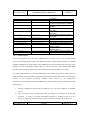
Ping test:
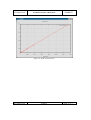
Several pings with different size have been sent from the Windows Home PC (Windows 2000)
through ADSL to the LAP. Up to a size of 400Bytes the response time is about 10ms.
With bigger sizes packet loss is experienced.
IST-2000-25187
PUBLIC
Page 52 of 77
Deliverable D4.3
Evaluation of Phase I Field Trial
IST-2000-25187
Packet size (Byte) Response time (ms)
From the LAP
From the RG
50
100
200
400
TORRENT
From the Router
(core network)
<10
<10
<10
<10
<10
10
10
10
10
10
10
10
10
Between 10 and 20
Between 10 and 20
<10
36% lost
Between 20 and 30
40% lost
Between 20 and 31
48% lost
50% lost
500
1000
F8_Test4
TC Name:
Diagnosis (provision of system status information to user)
TC ID:
F8_Test4
Test Purpose:
This test is intended to ensure that both normal and fault information
from the system is presented accurately to the user in an
understandable manner.
The information should identify clearly which part of the system was
responsible for any loss of quality.
Test Configuration
and constraints:
See figure 1
Test Description:
Measurement
equipment used
Test Set-up:
No measuring equipment is required
Test Procedure:
The following circumstances are expected to produce information to
This test uses the Phase 1 configuration.
the end-user, that originates from – or is passed transparently through
- the RG and/or LAP:
•In
the Normal State
•Status
•Service
offerings that are available
•Service
currently in use
•User’s
IST-2000-25187
messages that the RG and LAP are operating correctly
current profile
PUBLIC
Page 53 of 77
Deliverable D4.3
Evaluation of Phase I Field Trial
IST-2000-25187
•Charging
•Error
•RG
information (on request)
Conditions:
is powered down
•LAP
•RG
TORRENT
is powered down
is faulty
•LAP
is faulty
•LAP
CAC reports that a new session cannot be accepted because the
link to the core network has insufficient capacity
The developers of the RG and the LAP should provide further
information about the messages that they propose to pass to the end
user, and the system operator. The format of the messages and the
presentation must be harmonised. The above list is not expected to be
exhaustive.
All of the above conditions (and any others identified later) will be
induced, and it will be checked if the appropriate message is
received.
Further diagnosis messages will appear in Phase 2, since more
services will be available, and they will be able to take a choice of
routes on both the access link and towards the core network.
In these cases, messages should inform the user about the route that
is being taken (if different to the normal one) and any cost/quality
implications that this will have.
Verdict Criteria:
Are all the given diagnostic messages produced in accordance with
the associated conditions?
The only diagnostic information is available from the J500 ADSL modem. Green and red lights
show the status of the WAN and LAN link. Detailed statistic information is available using the
web access to the modems.
After the different break downs during the tests all indications from the modem have been the
same as when it is working well.
F12_Test1
IST-2000-25187
PUBLIC
Page 54 of 77
Deliverable D4.3
Evaluation of Phase I Field Trial
IST-2000-25187
TORRENT
TC Name:
Emergency access to a basic service if mains power fails
TC ID:
F12_Test1
Test Purpose:
This test is intended to ensure that telephony access is still possible in
cases where:
1.)The RG and/or LAP is powered off
2.)The ADSL link is fully loaded
3.)The RG processor is overloaded
4.)The system is in an otherwise “crashed” or “hung” state
Test Configuration
and constraints:
Phase 1 configuration
Test Description:
Measurement
equipment used
Test Set-up:
No measuring equipment is required
Test Procedure:
The test procedures described below, are based on an architecture in
This test uses the Phase 1 configuration in figure 1.
which:
•The
access link from the ADSL port of the RG is connected to the
LAP
•There
is a passively separated ISDN access from the RG to the LAP
that is connected directly to a service provider. There is a data
path between the LAP and this service provider
•3
•A
PCs are connected to the RG via an Ethernet cable
regular telephone is connected to the RG (the Phase 1 scenario
does not include VoIP). When this telephone is used, the call
(whether emergency or not) goes via the ISDN link. The call is
never blocked by the RG or LAP.
The test procedures are:
•The
telephone is used to make a call, under the following conditions:
oThe system (RG and/or LAP) is powered off
oThe ADSL link is fully loaded by using the VoD
service on 2 of the PCs, and/or artificially generated
background traffic
oThe RG processor is overloaded
IST-2000-25187
PUBLIC
Page 55 of 77
IST-2000-25187
Deliverable D4.3
Evaluation of Phase I Field Trial
TORRENT
oAny other type of system failure (crash/hang) that
occurs during the tests
In the Phase 2 user trials, VoIP will be added. This implies additional
complexity, in so far as the VoIP traffic will take the ADSL route by
default. When this route is congested or faulty, it will be diverted to
the ISDN link, but the user must be notified, as this will involve an
additional charge, for the local access.
Based on the fact that a VoIP phone may use the facilities of a PC, it
is assumed that the VoIP telephone will not work when there is no
mains power, but this assumption may not be correct if the VoIP
device is self-contained.
Verdict Criteria:
Does the telephone call always work, during all of the abovementioned failure conditions?
Results:
The results of the tests will be recorded. Tests that fail will be
notified to the developers.
ISDN is not ready for testing. On the RGs and at the LAP PPP is not ready to use.
Anyway an ISDN emergency phone call should work. The NT to where the ISDN phone will be
connected works independent from the Hardware of the RG.
F12_Test2
TC Name:
Acceptable service selection time
TC ID:
F12_Test2
Test Purpose:
This test is intended to check that the performance of the system
(though only a prototype, and with a small number of users) is
acceptable. The VoD selection should occur as fast as any regular
Web browsing process. Having selected the video, the start of
playing should happen within 10seconds. It is expected that most of
this time will be taken up within the video server.
Test Configuration
and constraints:
Figure 1
Test Description:
IST-2000-25187
PUBLIC
Page 56 of 77
Deliverable D4.3
Evaluation of Phase I Field Trial
IST-2000-25187
TORRENT
Measurement
equipment used
Test Set-up:
Simple timing equipment is required
Test Procedure:
The user accesses the VoD service menu (possibly after going
This test uses the Phase 1 configuration.
through an authentication procedure). The response time for any
authentication procedure should be comparable with similar
transactions on the Web.
Once in the VoD selection menu, the user chooses one of the
available films. There may be subsequent informational messages
associated with the connection acceptance control (CAC)
mechanism, available capacity in the network and offers of
alternative qualities and prices. Any such messages should appear to
the user to be instantaneous responses from the network.
The last selection message will be an invitation to pay a given price
for the service.
Once the “accept” option is chosen, the film should start to play
within an acceptable period. 10 seconds is considered to be the
maximum waiting time. Most of this time should be taken within the
video server.
Verdict Criteria:
Is the response time from the network for all user requests
acceptable?
Results:
Pass
This test is only done with web browsing. Different web pages are selected from the home-pc2.
The same pages were also selected from a PC directly connected to the core network. There is no
notable difference discoverable.
F12_Test5
TC Name:
Reliability (error tolerant and stable, self-monitoring)
TC ID:
F12_Test5
Test Purpose:
This test is intended to assess the reliability of the system,
specifically concerning the features of:
IST-2000-25187
PUBLIC
Page 57 of 77
Deliverable D4.3
Evaluation of Phase I Field Trial
IST-2000-25187
•Error
TORRENT
tolerance (does the system allow unusual inputs? Does the
system “hang”?)
•Stable
(does the system “crash”? Does the system react in an
inconsistent manner? Does the system sometimes work,
sometimes not?)
•Self-monitoring
(if the RG or LAP fails, are the operator and the
user informed? Is the message/indicator appropriate and
correct?)
Test Configuration
and constraints:
Figure 1
Test Description:
Measurement
equipment used
Test Set-up:
No measuring equipment is required
This test uses the Phase 1 configuration. It is applicable to all the
tests.
Test Procedure:
During all the tests, the system will be monitored for error tolerance,
stability and self-monitoring. Any such occurrences will be recorded.
Verdict Criteria:
Are commands accepted that are not in the instructions?
Are parameters, or parameter values, accepted that are not in the
instructions?
Does any part of the system crash, or become in a state where no
inputs are accepted, and a re-start is necessary?
Does the system sometimes react differently to the same commands?
If the RG or LAP fails, are the operator and the user informed?
Are failure messages/indicators appropriate and correct?)
Results:
All unexpected/faulty conditions will be recorded and reported to the
developers.
ADLS link
The ADSL link is not very stable. Running connections can suddenly break down without any
indication from the Modem on the LAP site. To establish the link again the LAP subsystem has to
be rebooted. A reset (switch off/on) of the J500 modem doesn't help. Breakdowns of the line
happen much more between RG1 and the LAP than one the link with RG2.
IST-2000-25187
PUBLIC
Page 58 of 77
IST-2000-25187
Deliverable D4.3
Evaluation of Phase I Field Trial
TORRENT
ADLS Modem J500 at RG1
The ADSL link between RG1 and the LAP is breaking down too often not allowing that the tests
could be done with the depth foreseen.
It seems that the problem could be at the J500 of RG1. Changing it with the modem of RG2
moves the problem to RG2.
ADLS Modem J500 at RG2
While changing routing entries on the modem the http service died from time to time.
Pings to modem are replied but the http service is blocked. Only power off/on helps but unsaved
changes are lost.
LAP
The system is not ready to use after boot or reboot.
Some basic set-up has to be done manually:
•Starting
the ATM part at the Management Subsystem
•Starting
ATM switching at Access Network Subsystems
•Entering
the IP Routes for the access to the home networks.
5 Analysis of Results
The whole system is set up with IPv4.
Due to some problems encountered and not yet solved on the integration of ADSL LAP and RG
the throughput is not the one expected.
It was also performed stress testing with IPv6 traffic from the RG through the management blade
of LAP to core blade of the LAP on pure Ethernet. Initially there was some trouble and also
packet loss (independently of the packet size), which occurred due to electrical contact problems
of one of the Ethernet cards on the management blade. After fixing this, everything worked well.
There was no trouble with the different kernel versions on the RG and on the LAP. It was
possible to transfer packets up to a size of roughly 11k on IPv4 and IPv6 over the IPB of the LAP.
IST-2000-25187
PUBLIC
Page 59 of 77
IST-2000-25187
Deliverable D4.3
Evaluation of Phase I Field Trial
TORRENT
The ADSL link is not very stable and the packet loss is probably due to it. Running connections
can suddenly break down without any indication from the modem on the LAP site having to do
with limitations coming from physical layers.
The information status concerning the LAN and WAN link is provided by the LEDs information
available at the modem. Detailed statistical information is available using the web access to the
modems.
A T-RG also provides diagnostic information through the implemented Status Indication Tool.
The connection status with the LAP as well as the control of the fail over functionality is some
basic features of this tool.
ISDN is not ready for testing. On the LAP, PPP is not ready to use. ISDN on the T-RG is ready
for testing. The PPP configuration for the ISDN modem (netMod) has been done and tested with
the public ISDN network.
An ISDN emergency phone call work once the NT to where the ISDN phone is connected works
independent from the hardware of the RG. Power failure at the RG doesn't have any influence on
the phone.
Other important tests allow the verification that the system tested doesn’t introduce significant
delays concerning the access to web page.
IST-2000-25187
PUBLIC
Page 60 of 77
IST-2000-25187
Deliverable D4.3
Evaluation of Phase I Field Trial
TORRENT
6 Conclusions and Recommendations
The field trial for phase 1, namely MCLab trial, has been implemented according to [2].
Due to some project adjustments (departure of Versaware partner and migration to IPv6) the
testing plan described in [2] was not followed and the set of tests that were performed are
described in section 4.2 of this report.
The tests that were made on the developers (WP2 & WP3) labs are also described and presented
at the annex, section 7 of this deliverable.
MCLab trial had provided a controlled environment (laboratory/experimental environment) and
the first insight on the system functionalities, mainly the communication between the LAP and
the T-RG have been achieved, even if all the proposed tests and applications can’t be performed
due to first prototype integration.
In fact several problems have appeared and both H/W and S/W developers are working on in
order to solve it, one of them being the instability of the ADSL integration between RG and the
LAP and the other the integration of all software modules developed by different partners.
Nevertheless it should be kept in mind that TORRENT system is a prototype system and
consequently under specific performance aspects, TORRENT system could not perform so well
as commercial grade equipment.
A short summary containing the status of phase II field trials has been done. A more elaborated
report will be made [3].
In phase II the tests will be performed in an operator environment taking into account either
security aspects, access networks convergence, or communication to core networks through the
LAPs. One important aspect that is included in this report is the beginning of preparations for
IPv6 on all trial sites.
The implementations of TORRENT at network and application level can possibly take advantage
of the migration to IPv6.
Each trial exploitation plan is described. Despite some partners are still investigating the best way
to exploit in depth each trial, it can be noticed that the flexibility is expected to come from the
TORRENT concept in the perspective of: a) Offering a set of advantages to customer, by
providing interactivity between the system and the customer through the selection of most
appropriated network and the b) possibility of aggregation of access networks to core networks
according to rules established by the customer.
IST-2000-25187
PUBLIC
Page 61 of 77
IST-2000-25187
Deliverable D4.3
Evaluation of Phase I Field Trial
TORRENT
It is recommended that field trials phase II will provide both IPv4 and IPv6 capability and provide
some flexibility concerning the already defined applications and the planned set of tests to
perform, since they can vary depending on the evolution of TORRENT system.
IST-2000-25187
PUBLIC
Page 62 of 77
Deliverable D4.3
Evaluation of Phase I Field Trial
IST-2000-25187
TORRENT
7 Annex 1
7.1 Address Structure of the TORRENT test equipment in the MCLab
IP Address Configuration
nameserver 193.72.156.10
default gateway 193.71.156.94
eth1 193.72.156.82
2001:620:204:100::82/64
RG 0
10.0.0.10
192.168.0.1 J500
10.0.1.10
192.168.1.1
RG 1
eth0 192.168.1.1
wlan 192.169.21.1
fec0::3/128
Flextel I/O Module
wlan 192.169.20.1
fec0::3/128
eth0 192.168.0.1
J500
upper
Fujitsu
CO card 0
eth1 193.72.156.83
2001:620:204:100::83/64
RG 1
eth0 192.168.10.4
fec0::2:192:168:10:4/64
Fujitsu
CO card 1
lower
eth1 ?
Itf0 (atm0)
wlan ?
Itf1 (atm1)
eth0 193.72.156.81
fec0::1:193:172:156:81
2001:620:204:100:250:
C2ff:fe07:928e/64
IPv6 site local
segments
LAN -> 1
RG-LAP ->2
IPB ->3
Management
Subsystem
atm0 10.0.0.1
ipb0 192.168.0.1
fec0::3:192:168:0:1 atm1 10.0.1.1
Access
Network
Subsystem
eth1 192.168.10.5
fec0::2:192:168:10:5
eth0 192.168.1.2
eth0 193.72.156.84
fec0::1:193:72:156:84
2001:620:204:100:250:
c2ff:fe07:93a6/64
Core
Network
Subsystem
Itf2 (atm2)
Itf3 (atm3)
ipb0 192.168.0.3
fec0::3:192:168:0:3
ipb0 192.168.0.2
MCLab LAN
Figure 20: Addressing structure of first integrated TORRENT tests
7.2 LAP - Configuration info for extern access to the LAP in MCLAB
o IP addresses
o
o
o
193.72.156.81 (in use - logical address flextel01)
193.72.156.82 (available but not in use)
193.72.156.83 (available but not in use)
o Gateway
o
193.72.156.94
o DNS
o
o
193.72.156.10 (Primary)
193.72.156.13 (Secondary)
IST-2000-25187
PUBLIC
Page 63 of 77
Deliverable D4.3
Evaluation of Phase I Field Trial
IST-2000-25187
TORRENT
o Net Mask
o
255.255.255.224
Login to the Subsystems of the LAP at MCLAB
Info for logging on as root to each subsystem:
o
Login: root
o
Password;
flextel
On each subsystem the following login (NO root rights) has been created:
o
Login: torrent
o
Password:
basel
LAMA Notes
o
LAMA Daemon
o
To run a management application remotely to the LAP you must follow these
steps:
§
Install in your system under the directory /etc the file lamaapi.conf
§
Set an entry in the /etc/services with:
•
§
o
“lamad
1977/tcp”
The lamaapi.conf file will contain the following entries
•
“LamaHost=193.72.156.81”
•
“LamaPort=lamad”
In the LAP actual configuration you have three PM plugged on the slots 0
(Management Subsystem), 3 (Access Network Subsystem) and 6 (Core Network
Subsystem)
o
LAMA CSM Daemon
o
To run a management application accessing platform info remotely to the LAP
you must follow these steps:
§
Install in your system under the directory /etc the file csmapi.conf
§
Set an entry in the /etc/services with:
•
§
The csmapi.conf file will contain the following entries
•
IST-2000-25187
“csmd 9002/tcp”
“CsmHost=193.72.156.81”
PUBLIC
Page 64 of 77
Deliverable D4.3
Evaluation of Phase I Field Trial
IST-2000-25187
o
TORRENT
In the LAP actual configuration you have three PM plugged on the slots 0 (Management
Subsystem), 3 (Access Network Subsystem) and 6 (Core Network Subsystem)
7.3 ADSL Environment Activation
o
ADSL environment
o
To start up ADSL environment it is necessary to run on the Access Network
Subsystem the script /root/ADSL/atmadmin start
o
To stop ADSL environment it is necessary to run on the Access Network
Subsystem the script /root/ADSL/atmadmin stop
o
To start up the AAL5 switch it is necessary to run on the Access Network
Subsystem the daemon /root/SWITCH/aal5swd
o
AAL5 Switch
o
The AAL5 switch has been configured to switch packets between access network
subsystem and management subsystem because the core network subsystem is
used for kernel testing activities.
o
Flextel Management WEB interface
o
To connect to the Flextel Management WEB interface you have to connect from
your browser the URL http://193.72.156.81/cgi-flt/readonly/start.cgi
7.4 TTCP and NETPERF
TTCP and Netperf have been installed for measurements in the network. Use of TTCP: to start
ttcp you must be in /usr/bin , so for IPv4 ttcp -r -s to configure it as a receiver and ttcp -t -s "IP
address" as a transmitter. Two computers are needed and you can use the two RGs for IPv6:
ttcp -a inet6 -r -s as a receiver
ttcp -a inet6 -t -s "IPv6 address" to make it behave as a transmitter.
Hardware available during the integration session
In the following table the availability plan of LAP hardware for the test-beds is shown
Q.ty
Description
Where
1
Flextel Platform #1 for Test bed
LAP
2
ADSL/CO Fujitsu card
LAP
1
Ethernet card (Provided by MCLAB)
LAP
IST-2000-25187
PUBLIC
Page 65 of 77
IST-2000-25187
Deliverable D4.3
Evaluation of Phase I Field Trial
2
ADSL Intracom Modem – J500
RG+
1
ISDN/Modem Intracom
RG+
2
PC as RG+
RG+
1
Flextel Platform #2 for additional
tests
TORRENT
Support to test
environment
ADSL Connection
The ADSL connection between LAP and RG has been fully tested.
API ( LAMA and RG-API)
The API is installed at RG and LAP site.
LAMA primitives available at workshop time:
o
LamaSubSystemConf
o
LamaModuleGet
o
LamaModuleGetList
o
LamaModuleConfigure
o
LamaModuleConfigureList
o
LamaMasterConfigure
o
LamaSegmentGetList
o
LamaSegmentSetList
o
LamaSystemGetInfo
o
LamOsRestart
o
LamaModuleActivate
o
LamaModuleDeactivate
o
LamaModuleConnect
o
LamaSystemTune
o
LamaRetCodeToString
o
LamaChangeRole
o
LamaEventControl
o
LamaInfo
o
LamaModuleBoardCode
o
LamaIpItInfo
o
LamaRunCmd
IST-2000-25187
PUBLIC
Page 66 of 77
IST-2000-25187
Deliverable D4.3
Evaluation of Phase I Field Trial
TORRENT
RG-API available at RG+ at workshop time
Available LAMA delivered and tested using the WEB management interface for LAP.
Available RG-API installed and tested
Management at LAP and RG+
WEB based management software has been installed at LAP and RG+.
Remote Access
LAP and 2 RG+ have been configured to allow remote access.
Follow up last HW integration activity
A configuration where 2 RGs connected to the LAP via J500 ADSL modems reach a remote IP
PC has been tested and verified.
The configuration is shown in the next figure.
CLIENT
J500
ADSL
MODEMS
LAP Flextel
Platform
CLIENT
ETH
10/100
HUB
Figure 21: Configuration of the integration modules
During the test phase both, the CLIP at Access network subsystem and the AAL5 switch, have
been tested. The AAL5 traffic received from the ADSL card is switched on to the IPB while the
CLIP is running at the Core Subsystem.
The two environments are shown in more detail in the next figures.
IST-2000-25187
PUBLIC
Page 67 of 77
Deliverable D4.3
Evaluation of Phase I Field Trial
IST-2000-25187
TORRENT
CLIP rebuilt at Access Net Subsystem
Access Network
Subsystem
Core Network
Subsystem
IP
IP
CLIP
AAL5
FireStream
Drv
AAL5
over IPB
I
P
B
I
P
B
Driver
Fujitsu
CO card
CLIP
MAC
Driver
IPB
Eth card
ADSL
J500
Figure 22: CLIP rebuilt at access subsystem
IST-2000-25187
PUBLIC
Page 68 of 77
Deliverable D4.3
Evaluation of Phase I Field Trial
IST-2000-25187
TORRENT
CLIP rebuilt at Access Net Subsystem
Access Network
Subsystem
Core Network
Subsystem
IP
IP
CLIP
AAL5
FireStream
Drv
AAL5
over IPB
I
P
B
I
P
B
Driver
Fujitsu
CO card
CLIP
MAC
Driver
IPB
ADSL
Eth card
Path under test
J500
Figure 23: CLIP rebuilt at access sub-system with performance achievements
Connectivity has been tested used ftp and ping.
7.5 Measurements
The following plots are from IPv6 throughput measurements. The tools in use were bench6, bsort
and gnuplot.
IST-2000-25187
PUBLIC
Page 69 of 77
IST-2000-25187
7.5.1
Deliverable D4.3
Evaluation of Phase I Field Trial
TORRENT
Throughput IPB
Figure 24: Throughput at the IPB
IST-2000-25187
PUBLIC
Page 70 of 77
IST-2000-25187
Deliverable D4.3
Evaluation of Phase I Field Trial
TORRENT
Figure 25: Delay measurements
IST-2000-25187
PUBLIC
Page 71 of 77
IST-2000-25187
7.5.2
Deliverable D4.3
Evaluation of Phase I Field Trial
TORRENT
Throughput Core Blade
Figure 26: Throughput
IST-2000-25187
PUBLIC
Page 72 of 77
IST-2000-25187
Deliverable D4.3
Evaluation of Phase I Field Trial
TORRENT
Figure 27: Delay measurements
IST-2000-25187
PUBLIC
Page 73 of 77
IST-2000-25187
7.5.3
Deliverable D4.3
Evaluation of Phase I Field Trial
TORRENT
Throughput Core Blade – RG1
Figure 28: Throughput
IST-2000-25187
PUBLIC
Page 74 of 77
IST-2000-25187
Deliverable D4.3
Evaluation of Phase I Field Trial
TORRENT
Figure 29: Delay measurements
From the above pictures, the LAP shows a constant throughput, both at the IPB on the core blade
and in direction of the RG. The throughput in direction to RG is the maximum obtained
throughput in the downstream ADSL link.
IST-2000-25187
PUBLIC
Page 75 of 77
IST-2000-25187
Deliverable D4.3
Evaluation of Phase I Field Trial
TORRENT
Abbreviations
ADSL
Asynchronous Digital Subscriber Line
ATM
Asynchronous Transfer Mode
ATU-R
ADSL Transceiver Unit – Remote End
BER
Bit Error Rate
BERT
Bit Error Rate Tester VPI – Virtual Path Identifier
CBR
Constant Bit Rate
CDVT
Cell Delay Variation
IPER
Internet Protocol (IP) Error Ratio
IPLR
IP Loss Ratio
IPITd
IP Inter-arrival Time downstream
IPITu
IP Inter-arrival Time upstream
IPTD
IP Transfer Delay
L2F
Layer Two Forwarding
LAP
Local Access Point
L2TP
Layer Two Tunnelling Protocol
PCR
Peak Cell Rate
PPTP
Point-to-Point Tunnelling Protocol
PVC
Permanent Virtual Circuit
QoS
Quality of Service
RG
Residential Gateway
RTCP
Real Time Control Protocol
RTT
Round Trip Time
SCR
Sustainable Cell Rate
SLA
Service Level Agreement
SPR
Spurious Packet Rate
VCI
Virtual Channel Identifier
VBR
Variable Bit Rate
VoD
Video on Demand
VoIP
Voice over IP
IST-2000-25187
PUBLIC
Page 76 of 77
IST-2000-25187
Deliverable D4.3
Evaluation of Phase I Field Trial
TORRENT
8 References
[1]
TORRENT deliverable D4.1, “Metrics of field trials”, November 2001.
[2]
TORRENT deliverable D4.2, “Definition of Phase 1 field trials”, February 2002.
[3]
TORRENT deliverable D4.4, “Definition of Phase 2 field trials”, to be published in
project time month 23.
[4]
TORRENT deliverable D2.1, “TORRENT infrastructure”, October 2001
[5]
TORRENT deliverable D2.2, “API Interface Layer to TORRENT Software”, March 2002
IST-2000-25187
PUBLIC
Page 77 of 77