1
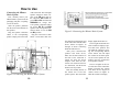
User’s Guide for
iBlaster Music System
Model No. 184
ongratulations on your purchase of the iBlaster
Music System from Excalibur Electronics, Inc.
You and your friends will enjoy hours of great
music with this innovative product. It’s compatible with
all iPod® models, CD players, sound cards, TV/VCD
and DVD players.
C
Your iBlaster Music System is easy to use, but be sure
to use it safely. Before starting, please read this manual
thoroughly, especially noting safety and care. Keep this
manual for reference.
This package includes one control box, one front right
speaker, one center speaker, one front left speaker, one
rear right speaker, one rear left speaker, subwoofer, one
remote control, audio signal cable and its user’s guide.
Table of Contents
Installing Battery . . . . . . . . . . . . . . . . . . . .page
Functions of Parts and Buttons . . . . . . . . . . page
How to Use . . . . . . . . . . . . . . . . . . . . . . . page
Connecting the iBlaster Music System page
Speaker Placement. . . . . . . . . . . . . . page
Troubleshooting. . . . . . . . . . . . . . . . page
Specifications . . . . . . . . . . . . . . . . . page
Special Care & Handling. . . . . . . . . . . . . . . page
Battery Information. . . . . . . . . . . . . . . . . . .page
Limited 90-Day Warranty. . . . . . . . . . . . . . page
3
4
9
9
14
14
15
16
16
19
Installing Battery
The legendary King Arthur brandished a magic sword, Excalibur,
from which we take our company
name. With this unique weapon in
his hands, he could not be
vanquished.
Although Excalibur Electronics
can’t claim the magical secrets
of Merlin, King Arthur ’s court
wizard, sometimes our patented
technology may make it seem as
if we could.
Your remote control requires
one lithium CR-2025 3V battery
(included). To replace the battery, press the tab on the base of
the remote to the right to release
the battery compartment, as
shown in Figure 1. Pull it out
like you would open a drawer.
Insert the CR-2025 3V battery,
making sure to match the polarity (+ and -) with the diagram
inside the battery compartment.
Reinsert the battery compartment.
We make you think.
iPod ® is a registered trademark of Apple Computer, Inc.
2
Figure 1
3
Layout of iBlaster Music System
Functions of Parts and Buttons
Control Box: Controls the entire speaker system.
LED DISPLAY: Displays the connected speakers and volume level.
IR RECEIVER: Point the remote control at this black circle. This
will receive the IR signal from the remote control.
STANDBY BUTTON: Press to turn the system ON or OFF. When it is
off or in stand-by mode, a blue light will surround the white button.
When the system is ON, the blue light is OFF.
5.1CH OUTPUT
the subwoofer.
JACK:
Connects the output 5.1CH signal cable to
Figure 2: Control Box
4
5
STEREO INPUT JACK: Connects to the audio device. Use this input
jack to connect your iPod®, DVD player, CD Player, sound card and
TV/VCD.
5.1CH
INPUT JACK:
Connects to a 5.1 channel sound card.
DC IN JACK: Connects to the subwoofer’s DC power input cable.
14) 5.1CH Input Jack(G9)
Subwoofer
15) DC Output Cable
FRONT RIGHT
right speaker.
FRONT LEFT
left speaker.
CENTER
speaker.
SPEAKER OUTPUT JACK
(FR): Connects to the front
SPEAKER OUTPUT JACK
(FL): Connects to the front
Figure 3: Subwoofer
SPEAKER OUTPUT JACK
(CEN): Connects to the center
REAR LEFT SPEAKER OUTPUT JACK (RL): Connects to the rear left
speaker.
REAR RIGHT
right speaker.
SPEAKER OUTPUT JACK
5.1CH INPUT
control box.
DC
16) AC Power On/Off Switch
17) AC Jack
JACK:
OUTPUT CABLE:
(RR): Connects to the rear
Connects the input 5.1CH signal cable to the
Speakers
SPEAKER CONNECTION CABLES: Connects to the corresponding
speaker output jack. For example, the front right speaker connection
cable connects to the FR output jack on the subwoofer. The specs on
the speaker cable are 1.8m x 3, 4.5m x 2. FR and FL are green, RR
and RL are black and SUB/CEN are orange.
Connects to the Control Box’s DC IN Jack.
AC POWER ON/OFF SWITCH: Switch ON to turn the subwoofer on.
Switch OFF to turn the subwoofer off.
AC POWER CABLE: Connects the power adapter cable to the electrical wall outlet.
Figure 4: Speaker
6
7
Audio Cable:
Transfers the audio signal from the control box to the subwoofer.
The spec on the audio cable is 2m x 1.
Figure 5: Audio Cable
5.1 Audio Cable:
Transfers the audio signal from a 5.1 audio device to the control
box and subwoofer.
Figure 7: Remote Control
right speakers. Press the DOWN button to decrease the volume of the rear left
and right speakers.
CENTER: Press the UP button to increase the volume of the center speaker. Press the DOWN button to decrease the volume of the center speaker.
FRONT: Press the UP button to increase the volume of the front left and
right speakers. Press the DOWN button to decrease the volume of the front
left and right speakers.
Figure 6: 5.1 Audio Cable
Remote Control:
Point the remote to the IR Receiver on the control box.
STANDBY: Press to turn the system ON or OFF. When it is off or in standby mode, a blue light will surround the white button on the control box.
When the system is on, the blue light is off.
MUTE: Press to mute the volume. Press again to turn the volume back on.
REAR: Press the
UP
MASTER: Press the UP button to increase the volume of all of the speakers. Press the DOWN button to decrease the volume of all of the speakers.
SUB: Press the UP button to increase the bass from the subwoofer. Press
the DOWN button to decrease the bass from the subwoofer.
5.1CH: Press to select the 5.1CH audio signal, when connected.
ST: Press to select the stereo audio signal, when connected.
button to increase the volume of the rear left and
8
9
How to Use
Connecting the iBlaster
Music System
of the subwoofer. The front right
speaker connection cable connects to the FR output jack on
the subwoofer. FR and FL are
green, RR and RL are black and
SUB/CEN are orange. The
1.8m speaker connection cables
are for the FR, FL and CEN
speakers. The 4.5m speaker connection cables are for the RR
and RL speakers.
First, carefully remove your
iBlaster Music System from the
packaging and place everything
on a level surface.
Slide the speaker platforms
into the slots on the backside of
the speakers.
Plug the speaker connection
cables to the corresponding
speaker output jack on the back
Figure 9: Connecting the iBlaster Music System
Plug the 3.5mm stereo cable
and/or 5.1CH audio cable into
the control box and plug the end
of the audio cable into the audio
device. Please see Figures 10
through 14 about connecting
different audio devices.
After you’ve connected the
speakers and audio device,
make sure the Power button on
the back of the subwoofer is
turned off. Plug the Power
Adapter cable from the subwoofer to an electrical wall outlet. Afterwards, turn the Power
button to the on position.
Figure 8: Connecting the iBlaster Music System
10
Push the Standby button on
the control box to boot the
speaker system. The control box
display lights should turn on.
The six lights around the face
of the control box display represent each of the speakers. You
can adjust the volume by pressing the corresponding buttons
on the remote. You can adjust
the volume for the front speakers, the center speaker, the rear
speakers, the bass (subwoofer)
or all speakers (master).
The row of lights on the center of the face of the control box
display represents the volume
level. There are five degrees of
volume. Please see Figure 15
about the control box display.
11
Figure 10: Sound Card
Figure 13: 5.1 Channel Sound Card
Figure 11: CD Player
Figure 14: DVD Player
BEFORE CONNECTING OR DISCONNECTING
ANY CABLE, MAKE SURE THAT THE SPEAKER’S POWER
BUTTON IS TURNED OFF.
Figure 12: TV/VCD
12
13
Speaker Placement
Figure 15: Display from the Control Box
To get the maximum benefit
of your surround-sound iBlaster
Music System, place the subwoofer on the ground horizontally. Keep a distance of approximately one foot between the
rear panel and walls. Set the left,
center and right speakers in the
front left, center and right. You
can either place the rear satellite
speakers behind the front left
and right speakers, as shown in
Figure 16. Or, you can place the
rear speakers in the top right and
left. If possible, you can place
these on a shelf or on a wall
mount, as shown in Figure 17.
Figure 16
Figure 17
Troubleshooting
If you set up your speakers near a television and it distorts the
colors on your television screen, try one of the following:
• Turn your iBlaster Music System off and unplug your television.
Wait 15 to 30 minutes, then plug everything back in.
TO
PREVENT THE RISK OF ELECTRIC SHOCK,
DO NOT REMOVE THE SPEAKER’S COVER.
14
• Move the speakers farther away from the television until
the distortion disappears.
• Check and see if there’s anything else that can be causing the
distortion. If so, move that object away.
15
Special Care & Handling
Specifications
DRIVER UNIT:
Subwoofer: 5.25''
•
Avoid rough handling such as bumping or dropping.
•
Avoid moisture and extreme temperatures. For best results, use
between the temperatures of 39º F and 100º F
(4º C and 38º C).
•
Clean using only a slightly damp cloth. Do not use cleaners
with chemical agents.
•
Do not set up speakers near windows or any other area
exposed to direct sunlight or prone to water seepage.
•
The power cord should be unplugged when not in use.
Satellite (Front/Rear): 3''
Satellite (Center): 3''
INPUT IMPEDANCE:
Subwoofer: 4 ohm
Satellite (Front/Rear): 4 ohm x 4
Satellite (Center): 4 ohm x 1
Battery Information
FREQUENCY RESPONSE:
Subwoofer: 60Hz~10KHz
Satellite (Front Rear): 120Hz~17KHz
Satellite (Center): 120Hz~17KHz
DIMENSIONS:
Subwoofer: 185 x 210 x 277 mm (WxHxD)
Satellite (Front/Rear): 96 x 124 x 98 mm (WxHxD)
Satellite (Center): 96 x 124 x 98 mm (WxHxD)
Control Box: 90 x 177.5 x 33 mm (WxHxD)
16
•
•
•
•
•
•
Use an alkaline battery for best performance.
Use one lithium CR-2025 3V battery (included).
Do not use a rechargeable battery.
Remove an exhausted battery from the unit.
Do not short circuit the battery terminals.
To avoid explosion or leakage, do not dispose of the battery in a fire or
attempt to recharge standard or alkaline batteries.
• Be sure to insert the battery with the correct polarities and always follow
the toy and battery manufacturers’ instructions.
• Remove the battery and store it in a cool, dry place when not in use.
• Always remove an old and dead battery from the product.
17
This device complies with Part 15 of the FCC Rules. Operation is subject to the following
two conditions: (1) this device may not cause harmful interference, and (2) this device must
accept any interference received, including interference that may cause undesired operation.
NOTE: This equipment has been tested and found to comply with the limits for a Class B digital
device, pursuant to Part 15 of the FCC Rules. These limits are designed to provide reasonable l
interference in a residential installation. This equipment generates, uses and can radiate radio
frequency energy and, if not installed and used in accordance with the instructions, may cause
harmful interference to radio communications. However, there is no guarantee that interference
will not occur in a particular installation. If this equipment does cause harmful interference to
radio or television reception, which can be determined by turning the equipment off and on,
the user is encouraged to try to correct the interference by one or more
of the following measures:
•
Reorient or relocate the receiving antenna.
•
Increase the separation between the equipment and receiver.
•
Connect the equipment into an outlet on a circuit different from that to which the
receiver is connected.
•
Consult the dealer or an experienced radio/TV technician for help.
Excalibur Electronics reserves the right to make technical changes
without notice in the interest of progress.
18
LIMITED
90-DAY
EXCALIBUR ELECTRONICS, INC.,
warrants to the original consumer that
its products are free from any electrical
or mechanical defects for a period of 90
DAYS from the date of purchase. If any
such defect is discovered within the
warranty period, EXCALIBUR ELECTRONICS, INC., will repair or replace
the unit free of charge upon receipt of
the unit, shipped postage prepaid and
insured to the factory address shown at
right.
WARRANTY
sion of incidental or consequential damages, so the above limitations and exclusions in these instances may not apply.
The only authorized service center in
the United States is:
Excalibur Electronics, Inc.
13755 SW 119th Ave
Miami, Florida 33186 U.S.A.
Phone: 305.477.8080
Fax: 305.477.9516
www.ExcaliburElectronics.com
Ship the unit carefully packed, preferably in the original carton, and send it
prepaid, and adequately insured. Include
a letter, detailing the complaint and
including your daytime telephone number, inside the shipping carton. If your
warranty has expired and you want an
estimated fee for service, write to the
above address, specifying the model and
the problem.
The warranty covers normal consumer
use and does not cover damage that
occurs in shipment or failure that results
from alterations, accident, misuse,
abuse, neglect, wear and tear, inadequate maintenance, commercial use, or
unreasonable use of the unit. Removal
of the top panel voids all warranties.
This warranty does not cover cost of
repairs made or attempted outside of the
factory.
PLEASE DO NOT SEND
YOUR UNIT WITHOUT
RECEIVING
AN ESTIMATE
FOR SERVICING.
WE CANNOT
STORE YOUR UNIT!
Any applicable implied warranties,
including warranties of merchantability and fitness, are hereby limited to 90 DAYS from the date
of purchase. Conse-quential
or incidental damages
resulting from a breach of
any applicable express or
implied warranties are
hereby excluded. Some
states do not allow
limitations on the
duration of implied
warranties and do
not allow exclu-
19
EXCALIBUR ELECTRONICS, INC.
13755 SW 119TH AVENUE
MIAMI, FL 33186 U.S.A.
PHONE: 305-477-8080
FAX: 305-477-9516
184 (MA) iBlaster 022706 V6
Play games live at:
www.ExcaliburElectronics.com