1
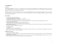
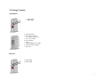
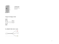
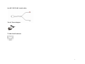
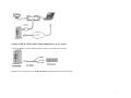
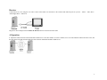
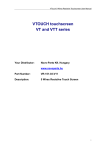
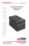
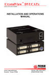
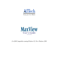
AITech
ProPC/TV Wireless
2.4 GHz Wireless (VGA to TV) Audio/Video Transmitter and Receiver
User’s Manual
AITech International
www.AITech.com
Contents
1.
Introduction………………….….……….2
2.
Package Contents………….……….……4
3.
How to connect ………………..………..7
4.
Operation……………………….…...…..9
5.
Troubleshooting…………………..…....10
6.
Specifications………………….……….12
1
1. Introduction
Overview
AITech ProPC/TV Wireless is a wireless PC-to-TV digital scan converter system capable of transmitting audio/video signals through walls up to 100 feet away.
This 2.4 GHz transmitter/receiver scan converter system enables you to transmit audio and video from your PC, VCR, DVD player or anything else with a
composite video output, and view everything on a TV monitor.
AITech used advanced wireless transmission technology in developing the ProPC/TV Wireless, which is highly resistant to external interference and can deliver
clear and sharp images and sound over distances of up to 100 feet. Universal applications are possible, as the ProPC/TV Wireless is capable of worldwide
NTSC and PAL television formats.
Key Features
•
2.4 GHz wireless Transmitter and Receiver
4 user-selectable channels increase flexibility and
performance
• Omni-directional built-in dipole A/V antennas
• The ProPC/TV Wireless supports NTSC and PAL worldwide television formats
• Converts VGA to Video! Transmitter connects to VGA card and sound card of any PC, and wirelessly transmits video/audio signals to receiver.
• Video and stereo audio transmission
• Resolution and refresh rate input up to 2048x1536 and 150Hz, respectively
• Clear and sharp video images and stereo audio quality output from the receiver
• Wireless transmission up to 200 feet in open areas, and up to 100 feet inside most homes, schools and offices, depending on the construction of the materials
between the transmitter and receiver.
• Compact size - antennas are embedded in the housing
• No software required
• FCC certified
• Compatible with camcorders and CMOS cameras
• Receiver wirelessly receives VGA/Video/audio signals from transmitter and output connects to TV, LCD TV monitor, VCR, Digital Video recorder, video
projector, speaker, or any device with video/audio input.
•
Multiple-operation modes:
• One-to-One (1 transmitter to 1 receiver)
• One-to-Multiple (1 transmitter to multiple receivers) One Transmitter can broadcast to any number of Receivers that are set to the same channel. Requires
additional Receivers, sold separately.
• Multiple-to-Multiple (multiple transmitters to multiple receivers) You may use up to four pairs of ProPC/TV Wireless simultaneously in the same area,
without interfering with each other, by setting each pair to operate on a different channel.
2
2. Package Contents
Transmitter
1. Signal light
2. Power light
1. Channel Switch
2. PAL / NTSC Switch
(Use NTSC in the USA)
3. A/V / VGA switch
4. Power Switch
5. A/V In
(From DVD Player or VCR)
6. VGA In (From Computer)
7. Power In
Receiver
1. Signal Light
2. Power Light
3
1. Channel Switch
2. Power Switch
3 A/V Out (To TV)
4. Power In
T-shaped VGA Bypass Cable
Two MD6M TO RCAM A/V cables
4
One DC3.5M TO RCA Audio cables
Two AC Power Adapters
75 Ohm Load Terminator
5
3. How to Connect
Transmitter
PC as A/V source: Connect PC’s VGA to the Transmitter’s VGA with the T-shaped VGA Bypass Cable and connect the PC’s audio output to Transmitter’s A/V
input with A/V cable and DC3.5 audio cable, as the picture below illustrates:
Connect to computer
Connect to Notebook
Connect the Notebook’s VGA to the Transmitter’s VGA with the T-shaped VGA Bypass Cable and attach the 75 Ohm Load Terminator to the Pass-Thru
Connector. Connect the PC’s Audio Output to Transmitter’s A/V Input with A/V cable and DC3.5 Audio Cable, as the picture below illustrates:
6
Connect to DVD, VCR or other Video Output Device as A/V source
Connect the DVD’s or VCR’s Audio and Video out to the A/V In using the A/V cable:
Plug the AC Power Adapter into the ProPC/TV Wireless Transmitter and wall electrical outlet.
7
Receiver
Connect Receiver to TV using the A/V cable. Connect color-coded A/V connectors to the Video-In and Audio-In jacks on your TV. Yellow = Video, Red =
Audio Right, White = Audio Left
Plug the AC Power Adapter into the ProPC/TV Wireless Receiver and wall electrical outlet.
4. Operation
1. Adjust the Channel Switch on both Transmitter and Receiver to the same channel. To select a channel, move one of the miniature channel switches to ON, and
the other three to the OFF position. Make the same selection on BOTH Transmitter and Receiver.
8
Example of Channel 1 selection:
Example of Channel 2 selection:
2. Set the NTSC/PAL switch on the Transmitter to the TV format used in your country. In the United States, set this to NTSC.
3. Set the AV-VGA switch on the Transmitter according to what video source you’re using. If you are connecting the ProPC/TV Wireless to your computer,
select VGA. If you are connecting the output from a VCR or DVD player to the ProPC/TV Wireless, set the switch to AV.
4. Turn on your TV and set it to view the video signal coming from the ProPC/TV Wireless. You must get it off of a channel number and onto the external Video
input. Most TV’s use names like Video, Video-1, AUX, Input etc. Most TVs allow you to make this setting using the TV’s remote control or sometimes the
buttons on the front of the TV. You may need to refer to your TV’s user manual to make the correct setting on your TV.
5. Turn on your PC, VCR or DVD player.
6. Turn the Transmitter’s and Receiver’s Power switches to ON.
5. Troubleshooting
•
•
•
•
•
•
•
•
•
No Picture or Sound
Make sure all connections are secure.
Make sure the channel selector on both Transmitter and Receiver are set to the same channel.
Check the power adapters to make sure they are properly connected, and that the Transmitter’s and Receiver’s power lights are on.
Make sure that your TV is set to view video from its external video input by selecting the proper input using the remote control. All TV’s are different. Refer to
your TV’s user manual for instructions on making this setting.
Cycle Power: Power OFF both Transmitter and Receiver using the On/Off switch, then power them both ON.
Check the AV-VGA switch on the Transmitter to make sure it is in the correct position.
Check the NTSC/PAL video format switch. In the United States, use NTSC.
Make sure you PC’s Resolution and Refresh Rate settings are no higher than 2048x1536 and 150 Hertz, respectively.
Check that all the cables are connected properly.
9
•
•
•
•
•
•
Interference in the Image and Sound
The ProPC/TV Wireless can transmit on four different channels. Try all four channels (set on Transmitter and Receiver) to find the cleanest, most
interference-free channel in your area.
Move your Transmitter and Receiver slightly to find the best reception position. Sometimes just moving them an inch or two will make a big difference in
reception quality.
Shorten the distance between your sender and receiver.
Microwave ovens, wireless home networking equipment and 2.4 GHz cordless phones all operate on the same frequency as the ProPC/TV Wireless, and may
cause interference. Try turning them off to eliminate interference.
Make sure your Transmitter and Receiver are on the same channel.
Picture on TV is too bright: If you are not connecting a PC monitor to the T-shaped VGA Bypass Cable, terminate the connection by attaching the 75 Ohm Load
Terminator to the Pass-Thru connector.
6. Specifications
Transmitter
VIDEO Input Level: 1Vp-p, supports PAL and NTSC format
AUDIO Input Level:
1Vp-p, stereo
Antenna:
Dipole
Operating Temperature:
-10° to +60°
VIDEO Output Formant:
PAL and NTSC format
2.4GHz wireless transmission:Frequency: 2400MHz - 2483MHz
Transmission Power: 10dBm
Channel Number: 4 (2414, 2432, 2450, 2468MHz)
Frequency Stability:
+-100KHz
Receiver
VIDEO Output Level:
1Vp-p
AUDIO Output Level:
1Vp-p, Stereo
Antenna:
Dipole
2.4GHz Wireless Transmission:Frequency 2400MHz—2483MHz
Receiver Sensitivity -85dBm
Channel Number: 4(2414,2432,2450,2468MHz)
Frequency Stability: +-100KHz
Warranties
10
This appendix documents the product warranty applicable to the United States only, as well as information about FCC radio frequency interference. For warranty
information outside of the United States, please contact your local distributor.
Limited Warranty
This AITech product is warranted to be free from failures due to defects in material and workmanship for one year from the date of original purchase as evidenced
by a copy of the original purchase receipt. During the warranty period, AITech, at AITech's sole discretion, will repair or replace at no charge, the product which,
in its opinion, is defective.
A Return Merchandise Authorization (RMA) number must be obtained from AITech prior to returning any merchandise for repair or replacement. Merchandise
sent to AITech without an RMA will be returned unopened.
The original purchaser is responsible for packing the product for shipment and for the charges to ship the failed product to AITech. AITech is responsible for
charges to ship the repaired or replaced product. If any charge to you is involved, the replacement product will be shipped C.O.D.
If the failed product has been modified in any way without the consent of AITech or if the failure is the result of misuse, abuse, or misapplication, AITech has no
obligation to repair or replace the failed product.
EXCEPT AS EXPRESSLY PROVIDED ABOVE, THE PRODUCT AND ACCOMPANYING WRITTEN MATERIALS (INCLUDING THE USER'S GUIDE)
ARE PROVIDED "AS IS" WITHOUT WARRANTY OF ANY KIND INCLUDING THE IMPLIED WARRANTIES OF MERCHANTABILITY AND
FITNESS FOR A PARTICULAR PURPOSE. AITECH SPECIFICALLY DOES NOT WARRANT THE OPERATION OF THE PRODUCT AND WILL NOT BE
LIABLE FOR ANY DIRECT, INDIRECT, CONSEQUENTIAL OR INCIDENTAL DAMAGES ARISING OUT OF THE USE OR INABILITY TO USE SUCH
PRODUCT EVEN IF AITECH HAS BEEN ADVISED OF THE POSSIBILITY OF SUCH DAMAGES. SOME STATES DO NOT ALLOW THE EXCLUSION
OR LIMITATION OF LIABILITY FOR CONSEQUENTIAL OR INCIDENTAL DAMAGE, SO THE ABOVE LIMITATION MAY NOT APPLY.
FCC Radio Frequency Interference Statement
This equipment has been tested and found to comply with the limits for a Class B digital device, pursuant to Part 15 of the FCC Rules. These limits are designed
to provide reasonable protection against harmful interference in a residential installation. This equipment generates, uses and can radiate radio frequency energy
and, if not installed and used in accordance with the instructions, may cause harmful interference to radio communications. However, there is no guarantee that
interference will not occur in a particular installation. If this equipment does cause harmful interference to radio or television reception, which can be
determined by turning the equipment off and then on again, you are encouraged to try to correct the interference by one or more of the following measures:
11
•
Reorient or relocate the receiving antenna
•
Increase the separation between the equipment and the receiver
•
Connect the equipment into an outlet on a circuit different from the circuit to which the receiver is connected
•
Consult the dealer or an experienced radio/TV technician for help
Shielded cables and I/O cords must be used for this equipment to comply with the relevant FCC regulations. Changes or modifications not expressly approved in
writing by AITECH may void the user's authority to operate this equipment.
AITech International
1288 Kifer Road, Suite 203
Sunnyvale, CA 94086
1-408-991-9699
[email protected]
www.AITech.com
12