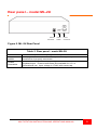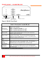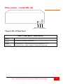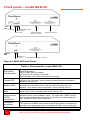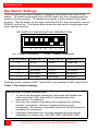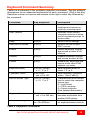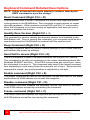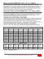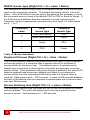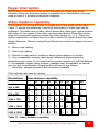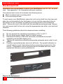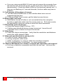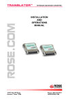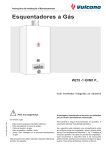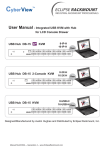
1
INSTALLATION AND OPERATIONS MANUAL 10707 Stancliff Road Houston, Texas 77099 Phone (281) 933-7673 WWW.ROSE.COM LIMITED WARRANTY Rose Electronics warrants the MultiStation™ to be in good working order for one year from the date of purchase from Rose Electronics or an authorized dealer. Should this product fail to be in good working order at any time during this one-year warranty period, Rose Electronics will, at its option, repair or replace the Unit as set forth below. Repair parts and replacement units will be either reconditioned or new. All replaced parts become the property of Rose Electronics. This limited warranty is valid only if repairs are performed by Rose Electronics or a Rose qualified service technician. This limited warranty is void if repairs are not performed by Rose Electronics or a Rose qualified service technician. This limited warranty does not include service to repair damage to the Unit resulting from accident, disaster, abuse, or unauthorized modification of the Unit, including static discharge and power surges. Limited Warranty service may be obtained by delivering this Unit during the one-year warranty period to Rose Electronics or an authorized repair center providing a proof of purchase date. If this Unit is delivered by mail, you agree to insure the Unit or assume the risk of loss or damage in transit, to prepay shipping charges to the warranty service location, and to use the original shipping container or its equivalent. You must call for a return authorization number first. Under no circumstances will a Unit be accepted without a return authorization number. Contact an authorized repair center or Rose Electronics for further information. ALL EXPRESS AND IMPLIED WARRANTIES FOR THIS PRODUCT INCLUDING THE WARRANTIES OF MERCHANTABILITY AND FITNESS FOR A PARTICULAR PURPOSE, ARE LIMITED IN DURATION TO A PERIOD OF ONE YEAR FROM THE DATE OF PURCHASE, AND NO WARRANTIES, WHETHER EXPRESS OR IMPLIED, WILL APPLY AFTER THIS PERIOD. SOME STATES DO NOT ALLOW LIMITATIONS ON HOW LONG AN IMPLIED WARRANTY LASTS, SO THE ABOVE LIMITATION MAY NOT APPLY TO YOU. IF THIS PRODUCT IS NOT IN GOOD WORKING ORDER AS WARRANTIED ABOVE, YOUR SOLE REMEDY SHALL BE REPLACEMENT OR REPAIR AS PROVIDED ABOVE. IN NO EVENT WILL ROSE ELECTRONICS BE LIABLE TO YOU FOR ANY DAMAGES INCLUDING ANY LOST PROFITS, LOST SAVINGS OR OTHER INCIDENTAL OR CONSEQUENTIAL DAMAGES ARISING OUT OF THE USE OF OR THE INABILITY TO USE SUCH PRODUCT, EVEN IF ROSE ELECTRONICS OR AN AUTHORIZED DEALER HAS BEEN ADVISED OF THE POSSIBILITY OF SUCH DAMAGES, OR FOR ANY CLAIM BY ANY OTHER PARTY. SOME STATES DO NOT ALLOW THE EXCLUSION OR LIMITATION OF INCIDENTAL OR CONSEQUENTIAL DAMAGES FOR CONSUMER PRODUCTS, SO THE ABOVE MAY NOT APPLY TO YOU. THIS WARRANTY GIVES YOU SPECIFIC LEGAL RIGHTS AND YOU MAY ALSO HAVE OTHER RIGHTS WHICH MAY VARY FROM STATE TO STATE. NOTE: This equipment has been tested and found to comply with the limits for a Class A digital device, pursuant to Part 15 of the FCC Rules. These limits are designed to provide reasonable protection against harmful interference when the equipment is operated in a commercial environment. This equipment generates, uses, and can radiate radio frequency energy and, if not installed and used in accordance with the instruction manual, may cause harmful interference to radio communications. Operation of this equipment in a residential area is likely to cause harmful interference in which case the user will be required to correct the interference at his own expense. ® IBM , AT, and PS/2 are trademarks of International Business Machines Corp. ® Microsoft and Microsoft Windows™ and Windows NT are registered trademarks of Microsoft Corp. Apple, Macintosh, and ADB are trademarks of Apple Computer, Inc. Sun is a registered trademark of Sun MicroSystems Inc. Multisync is a trademark of NEW Technologies, Inc. Any other trademarks mentioned in this manual are acknowledged to be the property of the trademark owner. Copyright Rose Electronics 1995 – 2002. All rights reserved. No part of this manual may be reproduced, stored in a retrieval system, or transcribed in any form or any means, electronic or mechanical, including photocopying and recording, without the prior written permission of Rose Electronics. Rose Electronics Part # MAN-ML – 1.2 Printed In the United States of America Revision 1.2 FCC/IC STATEMENTS, EU DECLARATION OF CONFORMITY FEDERAL COMMUNICATIONS COMMISSION AND INDUSTRY CANADA RADIO-FREQUENCY INTERFERENCE STATEMENTS This equipment generates, uses, and can radiate radio frequency energy and if not installed and used properly, that is, in strict accordance with the manufacturer’s instructions, may cause interference to radio communication. It has been tested and found to comply with the limits for a Class A computing device in accordance with the specifications in Subpart J of Part 15 of FCC rules, which are designed to provide reasonable protection against such interference when the equipment is operated in a commercial environment. Operation of this equipment in a residential area is likely to cause interference, in which case the user at his own expense will be required to take whatever measures may be necessary to correct the interference. Changes or modifications not expressly approved by the party responsible for compliance could void the user’s authority to operate the equipment. This digital apparatus does not exceed the Class A limits for radio noise emission from a digital apparatus set out in the Radio Interference Regulation of industry Canada. Le présent appareil numérique n’émet pas de bruits radioélectriques dépassant les limites applicables aux appareils numériques de la classe A prescrites dans le Règlement sur le brouillage radioélectrique publié par Industrie Canada. EUROPEAN UNION DECLARATION OF CONFORMITY ACCORDING TO COUNCIL DIRECTIVE 89/336EEC & 73/23EEC This equipment is in conformity with the protection requirements of the following Council Directives: The Declaration of Conformity is based upon compliance of the product with the following standards: EN55022: 1998 EN50082-1: 1997 EN55024: 1998 EN61000-3-2: 2000 EN60950: 2000 EN61000-3-3: 1995+A1 EN50081-1: 1992 TABLE of CONTENTS Content Page Disclaimer ......................................................................................................... 1 About this manual ............................................................................................. 1 Introduction ....................................................................................................... 1 Features ........................................................................................................... 3 Front panel – model ML-2U .............................................................................. 4 Rear panel – model ML-2U .............................................................................. 5 Front panel – model ML-4U .............................................................................. 6 Rear panel – model ML-4U .............................................................................. 7 Front panel – model MLK-2U ........................................................................... 8 Rear panel – model MLK-2U ............................................................................ 9 Installation procedure ..................................................................................... 10 Step 1. Connecting the keyboards, monitors, and mice ............................. 10 Step 2. Connecting the computer .............................................................. 11 Step 3. Connecting the bus cable (model MLK-2U only)........................... 12 Step 4. Powering up the system ................................................................ 13 Step 5. Testing the system ........................................................................ 13 Dip Switch Settings ......................................................................................... 14 Keyboard Command Detailed Descriptions ................................................... 16 Reset Command (Right Ctrl + R) ................................................................ 16 Identify Rom Version (Right Ctrl + I) ........................................................... 16 Keep Command (Right Ctrl + K) ................................................................. 16 Send Null to mouse (Right Ctrl + N) ........................................................... 16 Enable command (Right Ctrl + E) ............................................................... 16 Disable command (Right Ctrl + D) .............................................................. 16 Freeze command (Right Ctrl + F) ............................................................... 16 Mode command (Right Ctrl + M + 1, 2, or 3 + Enter) ................................. 17 Typematic value command (Right Ctrl + A + value + Enter) ...................... 17 RS232 mouse type (Right Ctrl + Q + value + Enter) .................................. 18 Keyboard timeout (Right Ctrl + H + value + Enter) ..................................... 18 Screen blanking time (Right Ctrl + V + value + Enter) ................................ 18 Power interruption .......................................................................................... 19 Video distance capability ................................................................................ 19 Rackmount kit ................................................................................................. 20 TroubleShooting ............................................................................................. 21 Safety.............................................................................................................. 23 Maintenance and Repair ................................................................................ 24 Technical Support ....................................................................................... 24 Figures_ Page Figure 1. ML-2U Front Panel ............................................................................ 4 Figure 2. ML-2U Rear Panel ............................................................................. 5 Figure 3. ML-4U Front Panel ............................................................................ 6 Figure 4. ML-4U Rear Panel ............................................................................. 7 Figure 5, MLK-2U Front Panel .......................................................................... 8 Figure 6. MLK-2U Rear Panel .......................................................................... 9 Figure 7. Connecting the KVM ....................................................................... 10 Figure 8. Connecting the Computer ............................................................... 11 Figure 9. Connecting Bus Cable ..................................................................... 12 Figure 10. Rackmount .................................................................................... 20 Tables__ Page Table 1. Front panel - model ML-2U ................................................................. 4 Table 2. Rear panel - model ML-2U ................................................................. 5 Table 3. Front panel - model ML-4U ................................................................. 6 Table 4. Rear panel - model ML-4U ................................................................. 7 Table 5. Front panels - model MLK-2U ............................................................ 8 Table 6. Rear panels - model MLK-2U ............................................................. 9 Table 7. Dip Switch Settings ........................................................................... 14 Table 8. Keyboard Commands ....................................................................... 15 Table 9. Typematic Value ............................................................................... 17 Table 10. Mouse translation ........................................................................... 18 Table 11. Video distance capability ................................................................ 19 Appendices Page Appendix A. General Specifications ............................................................... 25 Appendix B. Default Settings .......................................................................... 25 Appendix C. Parts and Cables ....................................................................... 26 INTRODUCTION Disclaimer While every precaution has been taken in the preparation of this manual, the manufacturer assumes no responsibility for errors or omissions. Neither does the manufacturer assume any liability for damages resulting from the use of the information contained herein. The manufacturer reserves the right to change the specifications, functions, or circuitry of the product at any time without notice. The manufacturer cannot accept liability for damages due to misuse of the product or other circumstances outside the manufacturer’s control. The manufacturer will not be responsible for any loss, damage, or injury arising directly or indirectly from the use of this product. (See limited warranty) About this manual This manual covers the installation, configuration, and the operation of the MultiStation series switches. The installation consists of installing and configuring the unit, connecting the computer, and connecting the KVM stations. Introduction ® Thank you for choosing Rose Electronics MultiStation™ for your multi-user application. Your new MultiStation is designed for a lifetime of trouble free operation. It will streamline you computer access by allowing a single computer to be accessed by multiple user workstations on a first come, first serve basis. The MultiStation sharing feature doesn't require any keyboard commands to use, but access can be controlled and there are special command features for special functions. The unit can also split the video signal allowing the same screen to be displayed on all monitors at the same time, or the video can be securely displayed on a single monitor. MultiStation is easy to install. You simply connect your computer and KVM stations to the appropriate MultiStation ports using the UltraCable. That’s really all there is to it, sharing is automatic. The status LEDs on the front panel flash once a second to indicate KVM to KVM communication is active. Any activity of the keyboard and mouse will also cause the LEDs to flash. MULTISTATION INSTALLATION AND OPERATIONS MANUAL 1 This manual describes all three models of MultiStation units. The features and commands are identical for the three models. Please disregard the diagrams and text that do not apply to your model. To acquaint you with your MultiStation unit, this manual first describes MultiStation’s front and rear panels. Installation and operation instructions show easy to understand diagrams that illustrates how to connect MultiStation to your computer, keyboards, video monitors, and mice. Package contents The MultiStation package for models ML-2U and ML-4U includes the MultiStation unit, a power transformer, and this installation and operation manual. The package for model MLK-2U includes the MultiStation local unit, a remote unit, 2 power transformers, and this installation and operation manual. Note: Cables are ordered separately. See Appendix C. Cables and rack mounts. Cable requirements MultiStation connects to a computer with a computer (CPU) adapter cable and to each keyboard, video monitor, and mouse with a Keyboard-VideoMouse (KVM) adapter cable. These cables are most commonly purchased with the MultiStation and will provide quick and trouble-free operation. Appendix C lists the most common cables. A distance of up to 100 feet from the CPU or KVM ports is supported with our extended distance cabling. To reach even longer distances or for special applications our ViewLink™ product can be used to reach a distance of up to 250 feet. The MLK-2U distributed units can have a distance of as much as 250’ between them. You will need the proper cable to interconnect the units. 2 MULTISTATION INSTALLATION AND OPERATIONS MANUAL Features Available in three models: ML-2U - standalone unit with 2 KVMs and 1 CPU ML-4U - standalone unit with 4 KVMs and 1 CPU MLK-2U – distributed units have local unit with 1 KVM and 1 CPU and remote unit with 1 KVM up to 250’ apart Fully automatic KVM sharing on first-come first-serve basis Adjustable keyboard timeout on each station Instant keyboard LED synchronization Dip switches allow commands to be disabled on each KVM The video can be displayed on all KVMs simultaneously Enable, disable, and freeze commands to control access of stations Adjustable video blanking timeout on each station Adjustable keyboard Typematic rate and delay on each station Automatic enable of PS/2 mouse when cable is reconnecting Supports XGA, SVGA, and VGA video Drives keyboard, video, and mouse signals up to 100 feet away Video resolution support up to 1280 x 1024 non-interlaced video Status LED on front panel flashes every second to show on-line status or when activity from keyboard or mouse received Supports both PS/2 and serial mouse Can translate from PS/2 to serial or serial to PS/2 mouse Supports PC keyboard modes 1, 2, and 3 Computer keyboard, video, and mouse use Rose universal DB25 connections Available in 117VAC or 230VAC models 19”, 23”, and 24” rack mount kits available Compatible with other Rose switches and extenders One-year warranty Made in USA MULTISTATION INSTALLATION AND OPERATIONS MANUAL 3 PANEL DESCRIPTION Front panel – model ML-2U Dip Switch Remote Video LED Status LEDs Power LED KVM connectors Computer connector Figure 1. ML-2U Front Panel Table 1. Front panel - model ML-2U Dip Switch Configuration Power LED Status LEDs Remote Video LED Keyboardvideo-mouse (KVM) connectors Computer connector Enables commands from keyboard at each KVM station. Up is enable, down is disable. KVM1 – dip switch on the right KVM2 – dip switch 2nd position from right When lit indicates the unit is powered on. The power is controlled by a switch on the rear panel and an external power transformer adapter supplied with the unit. Flashes once a second to show unit is on-line. This model internally consists of two boards. The one-second flashing indicates the boards are communicating with one another. Also flashes when keyboard or mouse activity occurs. When lit the CPU is sending video to KVM2 Keyboard, video monitor, and mouse are connected at this port using a keyboard-video-mouse adapter cable. The cable has a DB25 male at one end and appropriate connectors at the other end, depending upon your keyboard, video, and mouse type Your computer is connected at this port using a computer adapter cable. The cable has a DB25 male at one end and appropriate connectors at the other end, depending upon your keyboard, video, and mouse type* * See Appendix C for further cable information. 4 MULTISTATION INSTALLATION AND OPERATIONS MANUAL Rear panel – model ML-2U RS232 Connector Power Switch Power Connector Figure 2. ML-2U Rear Panel Table 2. Rear panel - model ML-2U RS232 Power switch Power connector RS232 serial port for factory diagnostics only Pressing the switch turns the unit on, provided supplied power transformer is properly connected. Power transformer included in package connects here. This is not a keyboard input. Power transformers are available for U.S. or international use. Input voltage is 17VAC with center tap. MULTISTATION INSTALLATION AND OPERATIONS MANUAL 5 Front panel – model ML-4U Dip Switch Remote Video LED Status LEDs Power LED Keyboard-VideoMouse connectors Computer connector Figure 3. ML-4U Front Panel Table 3. Front panel - model ML-4U Dip Switch Configuration Power LED Status LEDs Remote Video LED Keyboardvideo-mouse (KVM) connectors Computer connector Enables commands from keyboard at each KVM station. Up is enable, down is disable. KVM1 – dip switch on the right KVM2 – dip switch 2nd position from right KVM3 – dip switch 3rd position from right KVM4 – dip switch 4th position from right When lit indicates the unit is powered on. The power is controlled by a switch on the rear panel and an external power transformer adapter supplied with the unit. Flashes once a second to show unit is on-line. This model internally consists of two boards. The one-second flashing indicates the boards are communicating with one another. Also flashes when keyboard or mouse activity occurs. When lit the CPU is sending video to KVM2, KVM3, and KVM4 Keyboard, video monitor, and mouse are connected at this port using a keyboard-video-mouse adapter cable. The cable has a DB25 male at one end and appropriate connectors at the other end, depending upon your keyboard, video, and mouse type Your computer is connected at this prt using a computer adapter cable. The cable has a DB25 male at one end and appropriate connectors at the other end, depending upon your keyboard, video, and mouse type* * See Appendix C for further cable information. 6 MULTISTATION INSTALLATION AND OPERATIONS MANUAL Rear panel – model ML-4U RS 232 Connector Power Power switch connector Figure 4. ML-4U Rear Panel Table 4. Rear panel - model ML-4U RS232 Power switch Power connector RS232 serial port for factory diagnostics only Pressing the switch turns the unit on, provided supplied power transformer is properly connected. Power transformer included in package connects here. This is not a keyboard input. Power transformers are available for U.S. or international use. Input voltage is 17VAC with center tap. MULTISTATION INSTALLATION AND OPERATIONS MANUAL 7 Front panel – model MLK-2U LOCAL UNIT Dip Switch Remote Video LED Status LEDs Power LED Keyboard-VideoMouse connectors Computer connector REMOTE UNIT Status LEDs Power LED Keyboard-Video-Mouse connectors Figure 5, MLK-2U Front Panel Table 5. Front panels - model MLK-2U Dip Switch Configuration Power LED Status LEDs Remote Video LED Keyboardvideo-mouse (KVM) connectors Computer connector Only present on the local unit. Enables commands from keyboard at each KVM station. Up is enable, down is disable. Local KVM – dip switch on the right Remote KVM – dip switch 2nd position from right When lit indicates the unit is powered on. The power is controlled by a switch on the rear panel and an external power transformer adapter supplied with the unit. Flashes once a second to show unit is on-line. The one-second flashing indicates the local and remote units are communicating with one another. Also flashes when keyboard or mouse activity occurs. Only present on the local unit. When lit the CPU is sending video to the remote unit. Keyboard, video monitor, and mouse are connected at this port using a keyboard-video-mouse adapter cable. The cable has a DB25 male at one end and appropriate connectors at the other end, depending upon your keyboard, video, and mouse type Your computer is connected at this port using a computer adapter cable. The cable has a DB25 male at one end and appropriate connectors at the other end, depending upon your keyboard, video, and mouse type* * See Appendix C for further cable information. 8 MULTISTATION INSTALLATION AND OPERATIONS MANUAL Rear panel – model MLK-2U LOCAL UNIT REMOTE UNIT Figure 6. MLK-2U Rear Panel Table 6. Rear panels - model MLK-2U RS232 Power switch Power Bus out / in connection RS232 serial port for factory diagnostics only Pressing this switch turns the unit on or off Included power transformer connection Bus cable connection for the local and remote unit MULTISTATION INSTALLATION AND OPERATIONS MANUAL 9 INSTALLATION Installation procedure Step 1. Connecting the keyboards, monitors, and mice The Keyboard-Video-Mouse adapter cable connects one keyboard, one video monitor, and one mouse to the MultiStation. Cables will vary depending upon the connector type on your keyboard and whether you are using a PS/2 or serial mouse. You should have the correct cable to match your equipment’s connectors. These cables are available where you purchased your MultiStation. 1.1 Connect the KVM adapter cable’s DB-25M connector to the DB-25F connector labeled “KVM1” on the MultiStation front panel. 1.2 Connect the keyboard, mouse, and monitor cables to the corresponding connectors on the KVM adapter cable. 1.3 Repeat 1.1 and 1.2 for other KVM station(s) MLK-2U Receiver ML-4U ML-2U Figure 7. Connecting the KVM 10 MULTISTATION INSTALLATION AND OPERATIONS MANUAL Step 2. Connecting the computer A CPU adapter cable connects your computer to the MultiStation. The cable type will vary depending on the computer’s keyboard and mouse connectors. 2.1 Connect the CPU adapter cable’s DB-25M connector to the DB-25F connector labeled CPU on the MultiStation front panel. 2.2 Connect the keyboard, mouse, and monitor connectors on the CPU adapter cable to the corresponding ports on the computer. MLK-2U Transmitter ML-4U ML-2U Figure 8. Connecting the Computer MULTISTATION INSTALLATION AND OPERATIONS MANUAL 11 Step 3. Connecting the bus cable (model MLK-2U only) Step #3 applies to MultiStation model MLK-2U only. If your model is model ML-2U or ML-4U, skip this step. The bus cable (13W3M / 13W3M) connects between the local MultiStation and the remote unit. 3.1 Connect one end of the bus cable to the local unit’s “BUS OUT” 13W3F connector. 3.2 Connect the other end of the bus cable to the remote unit’s “BUS IN” 13W3F connector. Figure 9. Connecting Bus Cable WARNING: Avoid routing all cables near fluorescent lights, air conditioning compressors, or machinery that may create electrical interference. For the best quality video, use coax cable when the cable length exceeds 20 feet. 12 MULTISTATION INSTALLATION AND OPERATIONS MANUAL Step 4. Powering up the system 4.1 Connect the provided power adapter(s) to the power connector on the rear panel of MultiStation and to a power strip or wall outlet. Model MLK-2U requires two power adapters, one for the local unit and one for the remote unit. 4.2 Turn on all KVM video monitors. 4.3 Push the ON/Off switch on the rear panel to turn on the unit. Upon power-up the yellow status LED(s) will light briefly, and then flash at one second intervals indicating internal communication is established and the system is active. 4.4 Boot-up the computer. You should see the boot-up sequence on all KVM station monitors. If your computer was connected with power applied, you do not have to re-boot the computer. MultiStation emulates all keyboard and mouse functions for automatic boot-up. You may need to issue the mode-command or reset command to have proper keyboard and mouse communications. (See Table 8 for the proper command sequence) Step 5. Testing the system 5.1 With all cabling in place and power applied to all equipment, all the KVM video monitors should show the computers video. The default setting allows access to the computer from any KVM station. 5.1.1 From KVM station #1, verify that the keyboard and mouse functions properly 5.1.2 Verify keyboard and mouse functionality on all KVM stations. 5.2 There is a 2 second timeout default setting that inhibits the other KVM stations keyboard and mouse activity. Once the controlling KVM station has no keyboard or mouse activity for 2 seconds, another KVM station can gain control. Wait at least 2 seconds before verifying the other KVM stations. NOTE: Before entering any MultiStation keyboard commands, first press the right control key, then within 2 seconds, enter the command. Example: Reset command – press and release the right control key, then within 2 seconds, press the “R” key. Use only the numeric keys located above the keyboard when entering numeric commands. The numeric keypad is not recognized for valid numeric entries. MULTISTATION INSTALLATION AND OPERATIONS MANUAL 13 OPERATION Dip Switch Settings The front panel dip switch enables or disables commands from each KVM station. To enable commands from a KVM station put the corresponding dip switch in the up position. To disable commands, put the switch in the down position. The dip switch on the right controls KVM #1, the next switch controls KVM #2, and so on. The below table shows the dip switch configuration and each settings function. DIP SWITCH CONFIGURATION / DESCRIPTION 1 2 3 4 Up – enable commands Switch location 5 6 7 8 Down – disable commands Model ML-2U Model MK-4U Model MLK-2U 8 KVM 1 KVM 1 Local unit 7 KVM 2 KVM 2 Remote unit 6 No effect KVM 3 No effect 5 No effect KVM 4 No effect 1-4 No effect No effect No effect Example shown enables KVM 1 and KVM 3 and disables KVM 2 and KVM 4 Table 7. Dip Switch Settings IMPORTANT OPERATION NOTES: 1. To issue any keyboard command, first press and release the right control key (Ctrl) then within 2 seconds issue the command or it is aborted. 2. Use only the numeric keys above the keyboard for entering numeric commands. Numeric keypad entries are not recognized. All numeric commands must use the [Enter] key to complete the command. 3. Keyboard commands are not case sensitive and are shown capitalized for clarity only. DO NOT USE THE SHIFT KEY 14 MULTISTATION INSTALLATION AND OPERATIONS MANUAL Keyboard Command Summary Table 8 is a summary of the available keyboard commands. See the detailed descriptions for an expanded explanation of each command. [Ctrl] in the Key Sequence column is a press and release of the right control key followed by the command. Command Reset Key Sequence [Ctrl] R Rom Version [Ctrl] I Keep [Ctrl] K Send Null to mouse [Ctrl] N Enable [Ctrl} E Disable [Ctrl] D Freeze [Ctrl] F Keyboard mode [Ctrl] M x [Enter] x = 1, 2, or 3 Typematic Value [Ctrl] A xxx xxx = 0 to 127 RS232 Mouse Type [Ctrl] Q x [Enter] x = 0, 1, or 2 Keyboard timeout [Ctrl] H xxx xxx = 0 to 255 sec. Screen blanking time [Ctrl] V xxx [Enter] xxx = 0to 999 sec. Description Resets and enables keyboard and mouse on currently connected port Identifies ROM version, computer must be at some sort of command prompt to receive data Saves custom settings Re-sync an out-of-sync PS/2 mouse Enable keyboard, monitor, and mouse at other KVM stations. Disable keyboard, monitor, and mouse at other KVMs Disable only keyboard and mouse at the other KVM stations, not video. Sets keyboard mode to mode 1, 2, or 3. Sets keyboard Typematic action. (See Table 9) Translates the KVM mouse type to match the computer mouse type. 0 = Auto detect 1 = PS/2 computer 2 = Serial computer (See detailed description) Sets time computer becomes accessible from another KVM station Sets time screen blanks with no keyboard/mouse activity Table 8. Keyboard Commands MULTISTATION INSTALLATION AND OPERATIONS MANUAL 15 Keyboard Command Detailed Descriptions NOTE: Follow all inputs that require entering a numeric value by the KEEP command to save the change. Reset Command (Right Ctrl + R) The reset command is used to reinitialize the mouse and keyboard without cycling power on the MultiStation. This command is rarely issued on newer operating systems. Older systems running DOS and Win 3.1 may need to issue this command or you are running an application that does not use a mouse or disables the mouse. Identify Rom Version (Right Ctrl + I) This command is used to identify the firmware version level installed in the MultiStation unit. Prior to issuing this command, your computer must be at a command prompt for MultiStation to respond with the version level. Keep Command (Right Ctrl + K) The keep command saves all current custom settings in non-volatile memory and become the power-up settings. Send Null to mouse (Right Ctrl + N) The Null command is used to re-synchronize an out-of-sync PS/2 mouse. This command is usually not necessary on the newer operating systems like Windows 95/98/NT and Unix. If the PS/2 mouse does get out-of-sync, issue this command to re-sync it. This command may need to be issued a second time depending on how many bytes the mouse is out of sync. Each time this command is issued, the synchronization is adjusted by one byte. Enable command (Right Ctrl + E) The enable command will restore the keyboard, mouse and video to the share mode where all KVM stations can access the computer. Disable command (Right Ctrl + D) The disable command disables the keyboard, mouse, and turns off the video on all KVM stations except the one issuing the command. Freeze command (Right Ctrl + F) The freeze command disables the keyboard and mouse but not the video on all KVM stations except the one issuing the command. 16 MULTISTATION INSTALLATION AND OPERATIONS MANUAL Mode command (Right Ctrl + M + 1, 2, or 3 + Enter) MultiStation automatically detects the computer’s keyboard mode upon computer boot-up. If the computer is already booted and then connected to MultiStation, the computer’s keyboard mode can not be detected and the mode stored in non-volatile memory is used. If the mode is incorrect, either re-boot the computer or issue the correct mode command. Typematic value command (Right Ctrl + A + value + Enter) The Typematic setting is used to adjust the way the keyboard acts with a key is held down to repeat itself like moving the cursor across a line. The value entered is a combination of the key rate value and the delay value. The Typematic value is determined by the equation: Typematic Value = Rate Value + Delay Value The Typematic value is determined from Table 9 below. This table shows the rate and delay values to use to determine the Typematic value. Select a rate in keys/sec and note the adjacent rate value. Next select a delay in milliseconds and note the delay value. Add the two values together and this will be the Typematic value to enter. For example to use a rate of 16.0 keys/sec and a delay of 500 millisecond delay, the Typematic value = 7 + 32 = 39. This value would be entered as Right Ctrl A 39 Enter. Typematic Rate Rate Rate Keys/sec Value Rate Rate Keys/sec Value Rate Rate Keys/sec Value Rate Rate Keys/sec Value 30.0 0 15.0 8 7.5 16 3.7 24 26.7 1 13.3 9 6.7 17 3.3 25 24.0 2 12.0 10 6 18 3.0 26 21.8 3 10.9 11 5.5 19 2.7 27 20.0 4 10.0 12 5.0 20 2.5 28 18.5 5 9.2 13 4.6 21 2.3 29 17.1 6 8.8 14 4.3 22 2.1 30 16.0 7 8.0 15 4.0 23 2.0 31 Typematic Delay Delay in milliseconds Delay Value Delay in milliseconds Delay Value Delay in milliseconds Delay Value Delay in milliseconds Delay Value 250 0 500 32 750 64 1000 96 Table 9. Typematic Value MULTISTATION INSTALLATION AND OPERATIONS MANUAL 17 RS232 mouse type (Right Ctrl + Q + value + Enter) This command is used to match your KVM station’s mouse to the mouse type used on the connected computer. The default command value is 0 for autodetect. If the KVM station’s mouse type is the same as the computer’s mouse this command does not need to be issued (PS/2 to PS/2 or Serial to Serial). If the KVM mouse is different than the computer’s mouse, then issue the command using the appropriate command value from table 10. Valid entries are 0, 1, or 2. Command value KVM mouse type Computer mouse type PS/2 (auto detect) PS/2 Serial (auto detect) Serial 1 Serial PS/2 2 PS/2 Serial 0 Table 10. Mouse translation Keyboard timeout (Right Ctrl + H + value + Enter) This is a very powerful feature that allows other KVM users to take keyboard and mouse control of a computer after a specific time of no keyboard or mouse activity by the active user. The default value is 2 seconds and is loaded upon connecting to the computer and when any keyboard or mouse activity occurs. Once keyboard and mouse activity is detected, the other KVM stations keyboard and mouse are inhibited until there is no keyboard or mouse activity from the controlling KVM station after the timeout value is reached. Valid entries are 0 – 255 seconds. A value of 255 seconds disables all other KVM stations until the command is issued again with a timeout value less than 255 seconds. Screen blanking time (Right Ctrl + V + value + Enter) This command sets the time the video will turn off with no keyboard or mouse activity detected. The video will display when any key is pressed or the mouse is moved. Valid entries are 0 – 999 seconds. 18 MULTISTATION INSTALLATION AND OPERATIONS MANUAL Power interruption MultiStation is immune to most power interruptions of less than three seconds. Since the keyboard power is supplied from MultiStation, you may need to reset it if a power interruption happens. Video distance capability The limitation on driving distance is usually due to the quality of the video. Table 11 shows the distances, resolution and quality of video that can be expected. The table uses a letter, which shows the cable type, and a number that refers to the quality of the video, as described below. Rose Electronics does not recommend systems where the video quality is 1 or 2. There are further capabilities not listed here in order to send the higher resolution video longer distances. Please contact Rose Electronics technical support for more details. Z – Micro coax cabling C – Mini coax cabling 4 – Perfect or near perfect; unable to easily detect defects in screen. 3 – Very acceptable; images clear, small reflections around lettering depending upon color; if you examine the screen closely you will find defects. 2 – Acceptable; slightly fuzzy images; readable text, acceptable for casual use, but not for prolonged viewing as this will cause eye fatigue. 1 – Unusable; images smeared; text not easily readable. 75Hz refresh rate used for testing. Resolutions Video distance capability 5' 10' 20' 35' 800 x 600 Z4 C4 Z4 C4 Z4 C4 Z4 C4 Z4 C4 Z4 C4 Z3 C4 Z3 C4 1024 x 768 Z4 C4 Z4 C4 Z4 C4 1280 x 1024 Z4 C4 Z3 C4 1600 x 1200 Z3 C4 Z3 C3 640 x 480 50' 75' 100' 150' 200' C4 C4 C4 C3 C3 C4 C4 C4 C3 C3 Z3 C4 C4 C4 C3 C3 C2 Z3 C4 Z3 C3 C3 C3 C2 C2 C2 Z2 C3 C3 C3 C2 C1 C2 C2 Table 11. Video distance capability MULTISTATION INSTALLATION AND OPERATIONS MANUAL 19 RACKMOUNTING Rackmount kit Rackmount kits are available to mount your MultiStation in a 19”, 23”, or a 24” rack. See appendix C for description and part numbers. The optional rack mount kit includes the following items: Black anodized rack mounting shelf Four mounting screws. To rack mount your MultiStation, place the unit on the shelf from the rear and slide the unit forward into the front panel cut-out until the mounting holes in the bottom of the unit match up with the mounting holes in the rackmount shelf. Secure the unit to the shelf with the provided mounting screws. Secure the rack mount shelf to the rack using the appropriate size bolts, nuts and lock washers. The following guidelines should be observed when installing. a). b). c). d). e). Do not exceed the operating temperature of 0ο C to 45ο C. Do not block power supply vents or restrict airflow. Mechanical loading of the rack should be considered to prevent instability and possible tipping over. Tighten all connectors securely and provide adequate strain relief for all cables. Provide a grounded power source to all Units. Pay special attention to overall branch circuit load ratings before connecting equipment to this source. Overloaded circuits are potential fire hazards and can cause equipment failures or poor performance. Figure 10. Rackmount 20 MULTISTATION INSTALLATION AND OPERATIONS MANUAL TROUBLESHOOTING TroubleShooting The troubleshooting section is used as a guide to understanding the capabilities of the MultiStation and for general troubleshooting. If you have any problems or questions concerning the installation, operation or usage of the MultiStation that is not covered in this manual, please contact Rose Electronics for technical support. First check to assure that all cables are connected properly and securely and that power is applied to MultiStation, the KVM monitors and the connected computer. 1. Computer does not boot, keyboard / mouse error received a. Keyboard and mouse cables reversed b. Defective cable, try using a different cable c. Port on MultiStation is defective, try using another port d. Port on computer is defective, try plugging in the keyboard or mouse directly to the computer. If the computer does not boot properly, the computer port is defective 2. Mouse driver does not load a. See 1a - 1d b. If your computer uses a PS/2 mouse, the MultiStation or a PS/2 mouse must be connected to the computer at boot-up or the computer will not recognize a mouse present c. If your computer uses a serial mouse, make sure the right COM port is being used and the mouse driver syntax is correct 3. No video on KVM station’s monitor a. Video has been disabled by another KVM station b. KVM monitor can not display the resolution from the computer. Try connecting the monitor directly to the computer. If the monitor displays correctly, it should work correctly connected to MultiStation c. Cables are too long and the sync signals are distorted. Try shorter cables 4. No or incorrect response from the keyboard or mouse a. Keyboard and mouse have been disabled or frozen by another KVM station b. Keyboard, mouse, or computer cables loose or disconnected. Observe the status LED while typing on the keyboard. The LED should flash more rapidly when typing or moving the mouse. Use this test to verify a good keyboard and mouse connection to the unit. c. Power was disrupted for three seconds or less causing the keyboard or mouse to lock up. Disconnect the keyboard and plug it back in. d. The keyboard mode does not match the mode set in the computer. Issue the mode command for the correct keyboard. It may require rebooting the computer or resetting the keyboard by unplugging and plugging it back in. MULTISTATION INSTALLATION AND OPERATIONS MANUAL 21 e. If you are using model MLK-2U and can not access the computer from the remote unit, check the power on the local unit or the bus cable is disconnected. Check the status LEDs on the local and remote unit. If they are not flashing at 1 second intervals, the bus cable may have a problem. 5. Can’t access all functions of mouse a. The Microsoft IntelliMouse or other similar wheel mice are not supported at this time. b. If Microsoft Ball Point mouse, get the latest mouse drivers. 6. Mouse does not move a. MultiStation turned off after or not connected when the computer booted or application that uses the mouse was run. Exit and re-enter the application using the mouse or issue the reset command. 7. PS/2 mouse gets out of sync a. Reset the mouse (Right Ctrl key + “R”) b. Cabling was disturbed during mouse movement. Issue the null command once or twice to re-sync the mouse. 8. Video fuzzy a. Cable too long or wrong type. Verify that the resolution and distance match the video distance table. 9. Video not synchronized or wrong color a. Cable is loose, reseat cable b. Wrong computer cable used. c. Cable is defective, try using a cable from another computer d. Port on MultiStation is defective, try using another port 10. Status LED flashes at a steady 3 second rate, Unit does not respond a. Unit has a defective component and fails the self test. Unit must be serviced. 22 MULTISTATION INSTALLATION AND OPERATIONS MANUAL SAFETY Safety The MultiStation has been tested for conformance to safety regulations and requirements, and has been certified for international use. Like all electronic equipment, the MultiStation should be used with care. To protect yourself from possible injury and to minimize the risk of damage to the Unit, read and follow these safety instructions. Follow all instructions and warnings marked on this Unit. Except where explained in this manual, do not attempt to service this Unit yourself. Do not use this Unit near water. Assure that the placement of this Unit is on a stable surface or rack mounted. Provide proper ventilation and air circulation. Keep power cord and connection cables clear of obstructions that might cause damage to them. Use only power cords, power adapter and connection cables designed for this Unit. Use only a grounded (three-wire) electrical outlet. Keep objects that might damage this Unit and liquids that may spill, clear from this Unit. Liquids and foreign objects might come in contact with voltage points that could create a risk of fire or electrical shock. Operate this Unit only when the cover is in place. Do not use liquid or aerosol cleaners to clean this Unit. Always unplug this Unit from its electrical outlet before cleaning. Unplug this Unit from the electrical outlet and refer servicing to a qualified service center if any of the following conditions occur: The power cord or connection cables are damaged or frayed. The Unit has been exposed to any liquids. The Unit does not operate normally when all operating instructions have been followed. The Unit has been dropped or the case has been damaged. The Unit exhibits a distinct change in performance, indicating a need for service. MULTISTATION INSTALLATION AND OPERATIONS MANUAL 23 SERVICE and SUPPORT Maintenance and Repair This Unit does not contain any internal user-serviceable parts. In the event a Unit needs repair or maintenance, you must first obtain a Return Authorization (RA) number from Rose Electronics or an authorized repair center. This Return Authorization number must appear on the outside of the shipping container. See Limited Warranty for more information. When returning a Unit, it should be double-packed in the original container or equivalent, insured and shipped to: Rose Electronics Attn: RA__________ 10707 Stancliff Road Houston, Texas 77099 USA Technical Support If you are experiencing problems, or need assistance in setting up, configuring or operating your MultiStation, consult the appropriate sections of this manual. If, however, you require additional information or assistance, please contact the Rose Electronics Technical Support Department at: Phone: (281) 933-7673 E-Mail: [email protected] Web: www.rose.com Technical Support hours are from: 8:00 am to 6:00 pm CST (USA), Monday through Friday. Please report any malfunctions in the operation of this Unit or any discrepancies in this manual to the Rose Electronics Technical Support Department. 24 MULTISTATION INSTALLATION AND OPERATIONS MANUAL APPENDICES Appendix A. General Specifications Dimensions ML-2U/MLK-2U local/remote ML-4U 8.85”W x 2.10”H x 4.90”D 13.1”W x 5.25”H x 4.90”D Weight ML-2U/MLK-2U local/remote ML-4U 3.0 lbs 7.0 lbs Input Power 117 VAC adapter, 230 VAC optional Output Power 17VAC CT, 1.45A Connectors Power CPU/KVM BUS IN/OUT DIN5 DB25F 13W3F (MLK-2U only) Chassis Fully shielded, black painted steel Controls Power on/off switch, 8 position dip switch Indicators Power LED (Green) Status LED (Yellow) Remote Video LED (Yellow) Appendix B. Default Settings Setting Default Keyboard timeout 2 seconds Caps/Numlock/Scroll Numlock On Keyboard Mode 2 Screen Blank Time interval 0 (off) Typematic Value 43 (Rate=10.9 char/sec, delay=500 ms Mouse translation 0 (PS/2 in to PS/2 out, serial in to serial out MULTISTATION INSTALLATION AND OPERATIONS MANUAL 25 Appendix C. Parts and Cables Part Number Description Keyboard / Monitor / Mouse Adapter Cables CAB-ZX0606Mxx VGA (HD15F) / PS/2 (MD6F) / PS/2 (MD6F) CAB-CX0606Mxx UltraCable VGA (HD15F) / PS/2 (MD6F) / PS/2 (MD6F) Computer Adapter Cables CAB-ZX0606Cxx VGA (HD15M) / PS/2 (MD6M) / PS/2 (MD6M) CAB-CX0606Cxx UltraCable VGA (HD15M) / PS/2 (MD6M) / PS/2 (MD6M) Bus Cable CAB-SMBxx Coax bus cable 13W3M to 13W3M xx = cable length in feet Note: Serial mouse and AT keyboard cables are available. Contact your Rose Electronics representative for more information. Rack Mount RM-SV1 Black anodized / 19” rack RM-SV1/23 Black anodized / 23” rack RM-SV1/24 Black anodized / 24” rack 26 MULTISTATION INSTALLATION AND OPERATIONS MANUAL STANDALONE 2 KVMs to 1 CPU (Model ML-2U) STANDALONE 4 KVMs to 1 CPU (Model ML-4U) DISTRIBUTED 2 KVMs to 1 CPU (Model MLK-2U) MULTISTATION INSTALLATION AND OPERATIONS MANUAL 27 NOTES 28 MULTISTATION INSTALLATION AND OPERATIONS MANUAL 10707 Stancliff Road Houston, Texas 77099 Phone (281) 933-7673 WWW.ROSE.COM