1
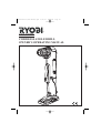
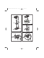
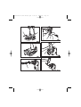
960223559-02(CDI-1801M/CDI-1802M)
CDI-1801M/CDI-1802M
CORDLESS IMPACT DRILL DRIVER
15
15
OWNER’S OPERATING MANUAL
Important!
It is essential that you read the instructions in this manual before
mounting and operating this machine.
Subject to technical modifications
English
b) Use safety equipment. Always wear eye protection.
Safety equipment such as dust mask, non-skid safety
shoes, hard hat, or hearing protection used for
appropriate conditions will reduce personal injuries.
c) Avoid accidental starting. Ensure the switch is in
the off position before plugging in. Carrying power
tools with your finger on the switch or plugging in
power tools that have the switch on invites accidents.
d) Remove any adjusting key or wrench before
turning the power tool on. A wrench or a key left
attached to a rotating part of the power tool may
result in personal injury.
e) Do not overreach. Keep proper footing and
balance at all times. This enables better control of
the power tool in unexpected situations.
f) Dress properly. Do not wear loose clothing or
jewellery. Keep your hair, clothing and gloves away
from moving parts. Loose clothes, jewellery or long
hair can be caught in moving parts.
g) If devices are provided for the connection of dust
extraction and collection facilities, ensure these
are connected and properly used. Use of these
devices can reduce dust related hazards.
GENERAL SAFETY RULES
WARNING
Read all instructions. Failure to follow all
instructions listed below may result in electric
shock, fire and/or serious injury. The term "power
tool'' in all of the warnings listed below refers to
your mains operated (corded) power tool or
battery operated (cordless) power tool.
SAVE THESE INSTRUCTIONS.
1) WORK AREA
a) Keep work area clean and well lit. Cluttered and
dark areas invite accidents.
b) Do not operate power tools in explosive
atmospheres, such as in the presence of flammable
liquids, gases, or dust. Power tools create sparks
which may ignite the dust or fumes.
c) Keep children and bystanders away while
operating a power tool. Distractions can cause you
to lose control.
2) ELECTRICAL SAFETY
a) Power tool plugs must match the outlet. Never
modify the plug in any way. Do not use any adapter
plugs with earthed(grounded) power tools.
Unmodified plugs and matching outlets will reduce risk
of electric shock.
b) Avoid body contact with earthed or grounded
surfaces such as pipes, radiators, ranges and
refrigerators. There is an increased risk of electric
shock if your body is earthed or grounded.
c) Do not expose power tools to rain or wet
conditions. Water entering a power tool will increase
the risk of electric shock.
d) Do not abuse the cord. Never use the cord for
carrying, pulling or unplugging the power tool. Keep
cord away from heat, oil, sharp edges or moving
parts. Damaged or entangled cords increase the risk
of electric shock.
e) When operating a power tool outdoors, use an
extension cord suitable for outdoor use. Use of a
cord suitable for outdoor use reduces the risk of
electric shock.
4) POWER TOOL USE AND CARE
a) Do not force the power tool. Use the correct power
tool for your application. The correct power tool will
do the job better and safer at the rate for which it was
designed.
b) Do not use the power tool if the switch does not turn
it on and off. Any power tool that can not be controlled
with the switch is dangerous and must be repaired.
c) Disconnect the plug from the power source before
making any adjustments, changing accessories, or
storing power tools. Such preventive safety measures
reduce the risk of starting the power tool accidentally.
d) Store idle power tools out of the reach of children
and do not allow persons unfamiliar with the
power tool or these instructions to operate the
power tool. Power tools are dangerous in the hands
of untrained users.
e) Maintain power tools. Check for misalignment or
bindling of moving parts, breakage of parts and any
other condition that may affect the power tools
operation. If damaged, have the power tool repaired
before use. Many accidents are caused by poorly
maintained power tools.
f) Keep cutting tools sharp and clean. Properly
maintained cutting tools with sharp cutting edges are
less likely to bind and are easier to control.
3) PERSONAL SAFETY
a) Stay alert, watch what you are doing and use
common sense when operating a power tool.
Do not use a power tool while you are tired or under
the influence of drugs, alcohol or medication.
A moment of inattention while operating power tools
may result in serious personal injury.
1
English
GENERAL SAFETY RULES
No load speed (impact mode):
-Lo speed (min-1)
0 - 5200
-Hi speed (min-1)
0 - 18200
35
Max.Torque (Nm)
Battery pack (Not included):
BPP-1817M/
BPP-1815M
Charger (Not included)
BC-1800/
BC-1815S
g) Use the power tool, accessories and tool bits etc., in
accordance with these instructions and in the
manner intended for the particular type of power
tool, taking into account the working conditions and
the work to be performed. Use of the power tool for
operations different from intended could result in
a hazardous situation.
0 - 5200
0 - 18200
35
BPP-1817M/
BPP-1815M
BC-1800/
BC-1815S
DESCRIPTION
5) BATTERY TOOL USE AND CARE
a) Ensure the switch is in the off position before
inserting battery pack. Inserting the battery pack into
power tools that have the switch on invites accidents.
b) Recharge only with the charger specified by the
manufacturer. A charger that is suitable for one type
of battery pack may create a risk of fire when used
with another battery pack.
c) Use power tools only with specifically designated
battery packs. Use of any other battery packs may
create a risk of injury and fire.
d) When battery pack is not in use, keep it away
from other metal objects like paper clips, coins,
keys, nails, screws, or other small metal objects
that can make a connection from one terminal to
another. Shorting the battery terminals together may
cause burns or a fire.
e) Under abusive conditions, liquid may be ejected
from the battery; avoid contact. If contact accidentally
occurs, flush with water. If liquid contacts eyes,
additionally seek medical help. Liquid ejected from the
battery may cause irritation or burns.
1.
2.
3.
4.
5.
6.
7.
8.
9.
10.
11.
12.
13.
Keyless chuck
Switch trigger
Direction of rotation selector (Forward/Reverse)
Screwdriver bits
Magnetic tray
Battery pack (NOT INCLUDED)
Latches
Auxiliary Handle
Depth Gauge Rod
Torque adjusting Ring
Drill mode
Impact mode
Reverse
14.
15.
Forward
Chuck jaws
OPERATION
TO INSTALL BATTERY PACK (NOT INCLUDED) (Fig.2)
Lock switch trigger on your drill by placing the
direction of rotation selector in center position.
Place battery pack in your drill. Align raised rib on
battery pack with groove inside drill.
Make sure the latches on battery pack snap in place
and battery pack is secured in drill before beginning
operation.
6) SERVICE
a) Have your power tool serviced by a qualified repair
person using only identical replacement parts.
This will ensure that the safety of the power tool
is maintained.
7) SPECIAL RULES
TO REMOVE BATTERY PACK(NOT INCLUDED) (Fig.2)
a) Wear ear protectors with impact drills. Exposure
to noise can cause hearing loss.
b) Use auxiliary handles supplied with the tool. Loss
of control can cause personal injury.
Lock switch trigger on your drill by placing the
direction of rotation selector in center position.
Locate latches of battery pack and depress to release
battery pack from your drill.
Remove battery pack from your drill.
SPECIFICATIONS
ADJUSTING THE AUXILIARY HANDLE (Fig. 3)
Model
Voltage
Chuck (mm)
Chuck sleeve
Switch
No load speed (drill mode):
-Lo speed (min-1)
-Hi speed (min-1)
CDI-1801M
18 V
13
Two
Variable speed
CDI-1802M
18 V
13
Single
Variable speed
0 - 400
0 - 1400
0 - 400
0 - 1400
Follow these steps to adjust the auxiliary handle.
Loosen the auxiliary handle by turning the knob
counterclockwise.
Rotate the auxiliary handle to the desired location.
Tighten the auxiliary handle securely by turning the
knob clockwise.
2
English
REVERSIBLE (Fig. 6)
OPERATION
This tool has the feature of being reversible. The direction
of rotation is controlled by a selector located above the
switch trigger. With the drill held in normal operating
position, the direction of rotation selector should be
positioned to the left of the switch for drilling. The drilling
direction is reversed when the selector is to the right of the
switch. When the selector is in center position, the switch
trigger is locked. To stop, release switch trigger and allow
the chuck to come to a complete stop.
ADJUSTING THE DEPTH GAUGE ROD (Fig. 4)
Follow these steps to adjust the depth gauge rod.
■
■
■
■
Lock the trigger switch by placing the rotation selector
in the center position.
Loosen the auxiliary handle by turning the knob
counterclockwise.
Adjust the depth gauge rod so that the drill bit
extends beyond the end of the rod to the required
drilling depth.
Tighten the auxiliary handle by turning the knob
clockwise.
ELECTRIC BRAKE
This drill has an electric brake. When the trigger switch is
released, the chuck stops turning. When the brake is
functioning properly, sparks will be visible through the
vent slots on the housing. This is normal and is the action
of the brake.
ADJUSTING THE TORQUE (Fig. 5)
OPERATION
The tool is equipped with an adjustable torque clutch for
driving different types of screws into different materials.
Adjust the torque as necessary.
ADJUSTING THE SPEED (Fig. 8)
We recommend that you use carbide-tipped bits and
select impact mode when drilling in hard material such as
brick, tile, concrete, etc.
■
Follow these steps to adjust the speed.
■
CAUTION
The impact drill is not designed for reverse
hammering. Failure to obey this caution may
result in property damage.
CAUTION
To prevent gear damage, always allow chuck to
come to a complete stop before changing the
speed or the direction of rotation.
SWITCH (Fig. 6)
■
■
For high speed: Slide the two-speed gear train switch
to “2.”
For low speed: Slide the two-speed gear train switch
to "1."
Note: If you have difficulty changing from one gear
range to the other, turn the chuck by hand until the
gears engage.
To turn your drill ON, depress the switch trigger.
To turn it OFF, release the switch trigger.
KEYLESS CHUCK (Fig. 7)
VARIABLE SPEED
Your drill has a keyless chuck. As the name implies,
you can hand tighten or release drill bits in the
chuck jaws. Rotate the chuck with your hand. Rotate the
chuck body with your other hand. The arrows on the
chuck indicate which direction to rotate the chuck body in
order to LOCK (tighten) or UNLOCK (release) the drill bit.
This tool has a variable speed switch that delivers higher
speed and torque with increased trigger pressure. Speed
is controlled by the amount of switch trigger depression.
SWITCH LOCK (Fig. 6)
WARNING
Do not hold chuck body with one hand and use
power of the drill to tighten chuck jaws on drill bit.
Chuck body could slip in your hand or your hand
could slip and come in contact with rotating drill bit.
This could cause an accident resulting in serious
personal injury.
The switch trigger can be locked in the OFF position. This
feature can be used to prevent the possibility of
accidental starting when not in use. To lock switch trigger,
place the direction of rotation selector (Forward/Reverse
Selector) in center position.
Note: When selector is in center position, switch trigger is
locked.
3
English
MAINTENANCE
ENVIRONMENTAL PROTECTION
WARNING
When servicing, use only identical replacement
parts. Use of any other part may create a hazard
or cause product damage.
Recycle raw materials instead of disposing as
waste. The machine, accessories and packaging should be sorted for environmental-friendly
recycling.
Avoid using solvents when cleaning plastic par ts.
Most plastics are susceptible to damage from various
types of commercial solvents and may be damaged by
their use. Use clean cloths to remove dirt, dust, oil,
grease, etc.
WARNING
Do not at any time let brake fluids, gasoline,
petroleum-based products, penetrating oils, etc.
come in contact with plastic parts. They contain
chemicals that can damage, weaken or
destroy plastic.
Do not abuse power tools. Abusive practices can damage
tool as well as workpiece.
WARNING
Do not attempt to modify this tool or create
accessories not recommended for use with
this tool. Any such alteration or modification is
misuse and could result in a hazardous condition
leading to possible serious personal injury.
4
GUARANTEE - STATEMENT
This Ryobi product is guaranteed from defects in material and workmanship, for a period of twenty-four (24) months,
effective and evidenced from date of original invoice or delivery note.
Defects caused by normal wear and tear, unauthorized/improper maintenance/handling or overload are excluded
from this guarantee as are accessories such as battery packs, bulbs, blades and bits, etc.
In the event of malfunction within the guarantee period, please return the product UNDISMANTLED with proof of
purchase, to your dealer or nearest Ryobi Service Centre.
Your statutory rights in respect of defective products remain unaffected by the warranty.
DECLARATION OF CONFORMITY
We declare under our sole responsibilty that this product is in conformity with the following standards or
standardised documents.
98/37/EC, 89/336/EEC, EN60745, EN61000, EN55014
CDl-1801M
CDI-1802M
Sound pressure level
89 dB( A )
89 dB( A )
Sound power level
Weighted root mean square
100 dB( A )
100 dB( A )
acceleration value.
15.9 m / s2
15.9 m / s2
Machine: CORDLESS IMPACT DRILL DRIVER
Name of company:
Address:
RYOBI TECHNOLOGIES (UK) LIMITED. Name/Title:
ANVIL HOUSE, TUNS LANE,
HENLEY-ON-THAMES,
Signature:
OXFORDSHIRE, RG9 1SA
UNITED KINGDOM
Tel: +44-1491-848700 Fax: +44-1491-848701
Type: CDl-1801M/
CDI-1802M
Mark Pearson
Managing Director
960223559-02
960223612-01(CAP-1801M).qxd
5/25/03
9:25 AM
Page A1
®
CAP-1801M
CORDLESS ANGLE DRILL
OWNER’S OPERATING MANUAL
960223612-01(CAP-1801M).qxd
5/25/03
9:25 AM
Page A2
960223612-01(CAP-1801M).qxd
5/25/03
9:25 AM
Page A3
960223612-01(CAP-1801M).qxd
5/25/03
9:25 AM
Page A4
Important!
It is essential that you read the instructions in this manual before
mounting and operating this machine.
Subject to technical modifications
960223612-01(CAP-1801M).qxd
5/25/03
9:25 AM
Page A5
English
PERSONAL SAFETY
GENERAL SAFETY RULES
■
WARNING
Read all instructions. Failure to follow all
instructions listed below may result in electric
shock, fire and/or serious injury. The term "power
tool'' in all of the warnings listed below refers to
your mains operated (corded) power tool or
battery operated (cordless) power tool.
■
SAVE THESE INSTRUCTIONS.
WORK AREA
■
■
■
■
Keep work area clean and well lit. Cluttered and
dark areas invite accidents.
Do not operate power tools in explosive
atmospheres, such as in the presence of
flammable liquids, gases, or dust. Power tools
create sparks which may ignite the dust or fumes.
Keep children and bystanders away while
operating a power tool. Distractions can cause you
to lose control.
■
■
■
ELECTRICAL SAFETY
■
■
■
■
■
Power tool plugs must match the outlet.
Never modify the plug in any way. Do not use any
adapter plugs with earthed (grounded) power tools.
Unmodified plugs and matching outlets will reduce
risk of electric shock.
Avoid body contact with earthed or grounded
surfaces such as pipes, radiators, ranges and
refrigerators. There is an increased risk of electric
shock if your body is earthed or grounded.
Do not expose power tools to rain or wet
conditions. Water entering a power tool will increase
the risk of electric shock.
Do not abuse the cord. Never use the cord for
carrying, pulling or unplugging the power tool.
Keep cord away from heat, oil, sharp edges or
moving parts. Damaged or entangled cords increase
the risk of electric shock.
When operating a power tool outdoors, use an
extension cord suitable for outdoor use. Use of a
cord suitable for outdoor use reduces the risk of
electric shock.
■
Stay alert, watch what you are doing and use
common sense when operating a power tool.
Do not use a power tool while you are tired or under
the influence of drugs, alcohol or medication.
A moment of inattention while operating power tools
may result in serious personal injury.
Use safety equipment. Always wear eye
protection. Safety equipment such as dust mask,
non-skid safety shoes, hard hat, or hearing protection
used for appropriate conditions will reduce
personal injuries.
Avoid accidental starting. Ensure the switch is in
the off position before plugging in. Carrying power
tools with your finger on the switch or plugging in
power tools that have the switch on invites accidents.
Remove any adjusting key or wrench before
turning the power tool on. A wrench or a key left
attached to a rotating part of the power tool may
result in personal injury.
Do not overreach. Keep proper footing and
balance at all times. This enables better control of
the power tool in unexpected situations.
Dress properly. Do not wear loose clothing or
jewellery. Keep your hair, clothing and gloves away
from moving parts. Loose clothes, jewellery or long
hair can be caught in moving parts.
If devices are provided for the connection of dust
extraction and collection facilities, ensure these
are connected and properly used. Use of these
devices can reduce dust related hazards.
POWER TOOL USE AND CARE
■
■
■
1
Do not force the power tool. Use the correct
power tool for your application. The correct power
tool will do the job better and safer at the rate for
which it was designed.
Do not use the power tool if the switch does not
turn it on and off. Any power tool that can not be
controlled with the switch is dangerous and must
be repaired.
Disconnect the plug from the power source
before making any adjustments, changing
accessories, or storing power tools.
Such preventive safety measures reduce the risk of
starting the power tool accidentally.
960223612-01(CAP-1801M).qxd
6/9/03
10:10 AM
Page A6
English
SERVICE
GENERAL SAFETY RULES
■
■
■
■
■
Store idle power tools out of the reach of children
and do not allow persons unfamiliar with the
power tool or these instructions to operate the
power tool. Power tools are dangerous in the hands
of untrained users.
Maintain power tools. Check for misalignment or
bindling of moving parts, breakage of parts and any
other condition that may affect the power tools
operation. If damaged, have the power tool repaired
before use. Many accidents are caused by poorly
maintained power tools.
Keep cutting tools sharp and clean. Properly
maintained cutting tools with sharp cutting edges are
less likely to bind and are easier to control.
Use the power tool, accessories and tool bits etc.,
in accordance with these instructions and in the
manner intended for the particular type of power
tool, taking into account the working conditions
and the work to be performed. Use of the power
tool for operations different from intended could result
in a hazardous situation.
SPECIFICATIONS
Voltage
No load speed
Battery pack (Not Included)
Charger (Not Included)
Max drilling capacity
- Wood
- Steel
■
■
■
■
18 V
0-1000 min-1
BPP-1817M / BPP-1815M
BC-1815S / BC-1800
38 mm
6.35 mm
DESCRIPTION
1.
2.
3.
4.
5.
6.
7.
8.
9.
10.
11.
12.
13.
BATTERY TOOL USE AND CARE
■
Have your power tool serviced by a qualified
repair person using only identical replacement
parts. This will ensure that the safety of the power
tool is maintained.
Ensure the switch is in the off position before
inserting battery pack. Inserting the battery pack
into power tools that have the switch on invites
accidents.
Recharge only with the charger specified by the
manufacturer. A charger that is suitable for one type
of battery pack may create a risk of fire when used
with another battery pack.
Use power tools only with specifically designated
battery packs. Use of any other battery packs may
create a risk of injury and fire.
When battery pack is not in use, keep it away
from other metal abjects like paper clips, coins,
keys, nails, screws, or other small metal objects
that can make a connection from one terminal to
another. Shorting the battery terminals together may
cause burns or a fire.
Under abusive conditions, liquid may be ejected
from the battery; avoid contact. If contact
accidentally occurs, flush with water. If liquid contacts
eyes, additionally seek medical help. Liquid ejected
from the battery may cause irritation or burns.
Keyless Chuck
Switch Trigger
Direction of Rotation Selector
Bit Storage
Swiveling Battery Foot
Latches
Battery Pack (Not included)
Chuck Collar
Screwdriver Bit
Bit Storage Area
Mallet (Not included)
Hex Key (Not included)
Screwdriver (Not included)
OPERATION
WARNING
Do not allow familiarity with tools to make you
careless. Remember that a careless fraction of a
second issufficient to inflict serious injury.
WARNING
Always wear safety goggles or safety glasses
with side shields when operating tools. Failure to
do so could result in objects being thrown into
your eyes, resulting inpossible serious injury.
WARNING
Do not use any attachments or accessories not
recommended by the manufacturer of this tool. The
use of attachments or accessories not
recommended can result in serious personal injury.
2
960223612-01(CAP-1801M).qxd
5/25/03
9:25 AM
Page A7
English
SWITCH LOCK (Fig. 3)
OPERATION
The switch trigger can be locked in the OFF position to
prevent the possibility of accidental starting when not
in use. To lock the switch trigger, place the direction of
rotation selector (Forward/Reverse Selector) in the
center position.
APPLICATIONS
You may use this tool for the following purposes:
■
■
■
■
Drilling in wood,
Drilling in ceramics, plastics, fiberglass, and
laminates,
Drilling in both hard and soft metals,
Using driving accessories, such as driving screws
with screwdriver bits.
VARIABLE SPEED
This tool has a variable speed switch trigger that delivers
higher speed and torque with increased trigger pressure.
Speed is controlled by the amount of switch trigger
depression.
TO INSTALL BATTERY PACK (NOT INCLUDED)
(Fig. 2)
■
■
Note: You might hear a whistling or ringing noise from the
switch during use. Do not be concerned; this is a normal
part of the switch function.
Lock the switch trigger on the drill by placing the
direction of rotation selector in the center position.
Place the battery pack in the drill. Align the raised rib
on the battery pack with the groove inside the drill.
REVERSIBLE (Fig. 3)
The direction of rotation is reversible and is controlled by
a selector located above the switch trigger. With the drill
held in normal operating position, the direction of rotation
selector should be positioned to the left of the switch
trigger for drilling. The drilling direction is reversed when
the selector is to the right of the switch trigger. When the
selector is in center position, the switch trigger is locked.
CAUTION
When placing battery pack in the tool, be sure
raised rib on battery pack aligns with the bottom
of the drill and latches into place properly.
Improper installation of the battery pack can
cause damage to internal components.
CAUTION
To prevent gear damage, always allow chuck to
come to a complete stop before changing the
direction ofrotation.
Make sure the latches on each side of the battery pack
snap into place and the battery pack is secured in the
drill before beginning operation.
To stop, release switch trigger and allow the chuck to
come to a complete stop.
TO REMOVE BATTERY PACK (NOT INCLUDED)
(Fig. 2)
■
■
■
KEYLESS CHUCK (Fig. 4)
Lock the switch trigger on the drill by placing the
direction of rotation selector in the center position.
Locate the latches on the side of the battery pack
and depress to release the batter y pack from
the drill.
Remove the battery pack from the drill.
The drill has a keyless chuck to tighten or release drill
bits in the chuck jaws. Grasp and hold the collar of the
chuck with one hand. Rotate the chuck body with your
other hand. This chuck has a rachetting design that
allows the user to hear a series of “clicks” while tightening
the jaws. This “clicking” will stop once the chuck and jaws
are secure. The arrows on the chuck indicate which direction to rotate the chuck body in order to LOCK (tighten) or
UNLOCK (release) the drill bit.
WARNING
Battery tools are always in operating condition.
Therefore, switch should always be locked when
not in use or carrying at your side.
WARNING
Do not hold the chuck body with one hand and
use the power of the drill to tighten the chuck
jaws on the drill bit. The chuck body could slip in
your hand or your hand could slip and come in
contact with rotating drill bit. This could cause an
accident resulting in serious personal injury.
SWITCH TRIGGER (Fig. 3)
To tur n the drill ON, depress the switch trigger.
To turn it OFF, release the switch trigger.
3
960223612-01(CAP-1801M).qxd
5/25/03
9:25 AM
Page A8
English
■
OPERATION
INSTALLING BITS (Fig. 4-5)
■
■
■
■
■
■
Lock the switch trigger by placing the direction of
rotation selector in center position.
Open or close the chuck jaws to a point where the
opening is slightly larger than the bit size you intend
to use. Also, raise the front of the drill slightly to keep
the bit from falling out of the chuck jaws.
Insert the drill bit straight into the chuck the full length
of the jaws.
Tighten the chuck jaws on the drill bit.
To tighten: grasp and hold the collar of the chuck with
one hand, while rotating the chuck body with your
other hand.
Note: Rotate the chuck body in the direction of the
arrow marked LOCK to tighten the chuck jaws.
Do not use a wrench to tighten or loosen the
chuck jaws.
■
WARNING
Make sure to insert the drill bit straight into the
chuck jaws. Do not insert the drill bit into the
chuck jaws at an angle then tighten, as shown in
figure 5. This could cause the drill bit to be
thrown from the drill, resulting in possible serious
personal injury or damage to the chuck.
■
WARNING
Be prepared for binding at bit breakthrough. When
these situations occur, drill has a tendency to grab
and kick opposite to the direction of rotation and
could cause loss of control when breaking through
material. If not prepared, this loss of control can
result in possible serious injury.
■
■
■
■
■
■
The drill's swiveling battery foot design allows you to
position the battery pack in the most convenient location.
The swiveling batter y foot has a degree scale
for accuracy.
Lock the switch trigger by placing the direction of
rotation selector in center position.
Loosen the chuck jaws from the drill bit.
To loosen: grasp and hold the collar of the chuck with
one hand, while rotating the chuck body with your
other hand.
Note: Rotate the chuck body in the direction of the
arrow marked UNLOCK to loosen the chuck jaws.
Do not use a wrench to tighten or loosen the chuck jaws.
Remove the drill bit from the chuck jaws.
MAINTENANCE
WARNING
When servicing, use only identical replacement
par ts. Use of any other par ts may create a
hazard or cause product damage.
WARNING
Always wear safety goggles or safety glasses
with side shields when operating tools. Failure to
do so could result in objects being thrown into
your eyes, resulting in possible serious injury.
BIT STORAGE (Fig. 6)
When not in use, bits provided with the drill can be
placed in the storage area located on the base of the drill.
WARNING
Always wear safety goggles or safety glasses
with side shields during power tool operation or
when blowing dust. If operation is dusty, also
wear a dust mask.
DRILLING (Fig. 7)
■
When drilling metals, use a light oil on the drill bit to
keep it from overheating. The oil will prolong the life of
the bit and increase the drilling action.
If the bit jams in workpiece or if the drill stalls, release
switch trigger immediately. Remove the bit from the
workpiece and determine the reason for jamming.
This drill has an electric brake. When the switch
trigger is released, the chuck stops turning. When the
brake is functioning properly, sparks will be visible
through the vent slots on the housing. This is normal
and is the action of the brake.
USING SWIVELING BATTERY FOOT (Fig. 8)
REMOVING BITS (Fig. 4-5)
■
The material to be drilled should be secured in a vise or
with clamps to keep it from turning as the drill bit
rotates. Hold the tool firmly and place the bit at the point
to be drilled. Depress the switch trigger to start the tool.
Move the drill bit into the workpiece applying only
enough pressure to keep the bit cutting. Do not force
or apply side pressure to elongate a hole.
When drilling hard smooth surfaces use a center
punch to mark the desired hole location. This will
prevent the drill bit from slipping off center as the
hole is started.
4
960223612-01(CAP-1801M).qxd
5/25/03
9:25 AM
Page A9
English
■
MAINTENANCE
WARNING
To avoid serious personal injury, always remove
thebattery pack from the tool when cleaning or
performing any maintenance.
■
GENERAL MAINTENANCE
■
Avoid using solvents when cleaning plastic parts. Most
plastics are susceptible to damage from various types of
commercial solvents and may be damaged by their use.
Use clean cloths to remove dirt, dust, oil, grease, etc.
Tap the hex key sharply with a mallet in a clockwise
direction. This will loosen the screw in the chuck for
easy removal.
Open the chuck jaws and remove the hex key.
Remove the chuck screw by turning it in a clockwise
direction.
Note: The screw has left hand threads.
Insert the hex key in chuck and tighten the chuck jaws
securely. Tap sharply with a mallet in a counterclockwise direction. This will loosen the chuck on the
spindle. It can now be unscrewed by hand.
TO RETIGHTEN A LOOSE CHUCK (Fig. 9-11)
WARNING
Do not at any time let brake fluids, gasoline,
petroleum-based products, penetrating oils, etc.,
come in contact with plastic parts. Chemicals can
damage, weaken ordestroy plastic which may
result in serious personal injury.
The chuck may become loose on the spindle and develop
a wobble. Periodically check the chuck screw for
tightness.
■
■
Only the parts shown on the parts list are intended to be
repaired or replaced by the customer. All other parts
should be replaced at a Ryobi Authorized Service Center.
■
CHUCK REMOVAL (Fig. 9-11)
■
To remove the chuck:
■
■
■
Lock the switch trigger by placing the direction of
rotation selector in center position.
Insert a 5/16 in. or larger hex key into the chuck of the
drill and tighten the chuck jaws securely.
5
Lock the switch trigger by placing the direction of
rotation selector in center position.
Open the chuck jaws.
Insert the hex key into the chuck and tighten the
chuck jaws securely. Tap the hex key sharply with a
mallet in a clockwise direction. This will tighten the
chuck on the spindle.
Open the chuck jaws and remove the hex key.
Tighten the chuck screw.
Note: The chuck screw has left hand threads.
960223612-01(CAP-1801M).qxd
5/25/03
9:25 AM
Page A10
GUARANTEE - STATEMENT
This product is guaranteed from defects in material and workmanship, for a period of twenty-four (24) months,
effective and evidenced from date of original invoice or delivery note.
Defects caused by normal wear and tear, unauthorized / improper maintenance/handling or overload are
excluded from this guarantee as are accessories such as battery packs, bulbs, blades and bits, etc.
In the event of malfunction within the guarantee period, please return the product UNDISMANTLED with proof
of purchase, to your dealer or nearest Ryobi Service Centre.
Your statutory rights in respect of defective products remain unaffected by the warranty.
DECLARATION OF CONFORMITY
We declare under our sole responsibility that this product is in conformity with the following standards or
standardised documents.
98/37/EC, 89/336/EEC, EN60745, EN55014, EN61000
73/23/EEC, EN50366
Machine: CORDLESS ANGLE DRILL
Type: CAP-1801M
Name of company:
Address:
Name/Title:
Ryobi Technologies (UK) Limited.
ANVIL HOUSE, TUNS LANE,
HENLEY-ON-THAMES,
OXFORDSHIRE, RG9 1SA
UNITED KINGDOM
Tel: +44-1491-848700 Fax: +44-1491-848701
Signature:
Mark Pearson
Managing Director
960223612-01(CAP-1801M).qxd
5/25/03
9:25 AM
Page A11
960223612-01