1
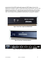
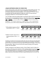
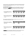
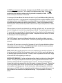
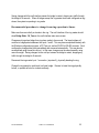
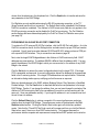
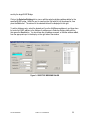
MODEL 2130
ELMC BRIDGE
FIAL INCORPORATED
710 CENTER STREET
OREGON CITY, OR 97045
503.607.1940
WWW.FIAL.COM’
DOCUMENT NUMBER 2130-040601
COPYRIGHT © 2001 BY FIAL INCORPORATED
NOTICE OF FCC COMPLIANCE
NOTE
This equipment has been tested and found to comply with the limits for a Class A digital
device pursuant to Part 15 of FCC Rules. These limits are designed to provide reasonable
protection against harmful interference when this equipment is operated in a commercial
environment. This equipment generates, uses and can radiate radio frequency energy and,
if not installed and used in accordance with the instruction manual, may cause harmful
interference to radio communication. Operation of this equipment in a residential area is
likely to cause harmful interference, in which case the user will be required to correct the
interference at his/her own expense.
Table of Contents
BRIEF DESCRIPTION...................................................................................................................................................1
ELMC PROTOCOL BACKGROUND ...........................................................................................1
ELMC BRIDGE CHARACTERISTICS.........................................................................................3
LINEAR NETWORK MODE OF OPERATION......................................................................4
SELECTIVE BRIDGING OPERATION .......................................................................................8
Selective Bridging Details ................................................................................................................................................... 8
PERFORMANCE MONITORING ....................................................................................................9
POWER ...............................................................................................................................................................9
INSTALLATION...........................................................................................................................................................10
USE AS ASYNCHRONOUS PORTS ...........................................................................................11
USE AS SYNCHRONOUS PORTS ...............................................................................................11
CRAFT PORT CONFIGURATION...............................................................................................................................13
MAIN MENU ....................................................................................................................................................13
MENU OPERATION ...............................................................................................................................14
RING OPERATION ..................................................................................................................................20
WINDOWS PROVISIONING PROGRAM....................................................................................................................23
Main Window................................................................................................................................................................ 23
PROVISIONING VIA THE WINDOWS CRAFT PORT CONNECTION .............................................. 24
PROVISIONING VIA AN ELMC RS-422 PORT CONNECTION ........................................................... 25
MODEL 2130 ELMC BRIDGE SPECIFICATIONS .......................................................................................27
ELMC BRIDGE CONNECTOR PIN ASSIG NMENTS ...................................................................................29
ALCATEL 4000, 5606 SERIES RADIO, ASYNC ELMC CONNECTIONS, 19.2 KILOBITS ...............................................30
TABLE 4 CABLE FOR RADIO WIREWRAP BLOCK TO ELMC BRIDGE .....................................................................30
ALCATEL 6000, 8000 SERIES RADIO ASYNC ELMC CONNECTIONS, 19.2 KILOBITS ..............................................30
TABLE 5 CABLE FOR 6000, 8000 SERIES RADIO TO ELMC BRIDGE .....................................................................30
CHANNEL BANK RS-530 INTERFACE (USING A DB25 CONNECTOR)........................................................................31
CHANNEL BANK RS-449 INTERFACE (USING A DB37 CONNECTOR)........................................................................32
CHANNEL BANK V.35 INTERFACE (USING THE M34 CONNECTOR) .........................................................................34
TYPICAL DATA PORT INTERFACE ..........................................................................................................................35
FIAL INCORPORATED
MODEL 2130 ELMC BRIDGE
i
BRIEF DESCRIPTION
The model 2130 ELMC Bridge is a packet-data buffering and re-synchronizing device. It is used to
interconnect Alcatel ELMC (Extended Link Monitoring and Control) data channels. The bridge has
five ports which operate at 19.2 kilobits per second asynchronous RS-422. These ports may be
connected to ELMC ports available on Alcatel 4000, 5606, 6000 and 8000 series radios. All five
ports may also operate in synchronous DTE mode for connection to a synchronous channel bank
card or radio overhead channel. The synchronous connection is used to interconnect bridges
along a backbone radio system, where each bridge also services one or more ELMC spurs. Port
five may also be operated in DCE synchronous mode, generating 64 kilobit transmit and receive
clock. This feature is used to interconnect two or more bridges to yield more ports. An RS-232
serial craft interface is used to configure the unit via a TTY terminal or terminal emulation program.
A Windows-based configuration program is also provided that can remotely configure the bridges.
ELMC bridges may be configured to operate in either linear or ring modes. In linear mode, ports 1
and 2 are connected to East and West bound legs respectively. In ring mode, ports 1 and 2 are
connected in clockwise and counter clockwise directions respectively. A 64 kilobit synchronous
path is generally used for the ring backbone. Ports 3, 4 and 5 are used for local drops (19.2
asynchronous) on the ring and also for spurs. A master ELMC bridge normally provides a break in
the ring. A break anywhere else in the ring is sensed by one or more slave ELMC bridges. They
then instruct the master bridge to start bridging ELMC packets across ports 1 and 2, thus healing
the ring.
The ELMC Bridge may be powered by 24 or 48 volt station battery, using positive or negative
ground. The ELMC Bridge is 1.75 inches high (1U) and is designed to mount in a 19 inch rack in
either flush or projection mounting configurations.
ELMC PROTOCOL BACKGROUND
The Extended Link Monitoring and Control Protocol was developed for provisioning, monitoring and
radio-to-radio communication in Alcatel microwave radios. ELMC information in the radio is
transported as packet data. Packets are of two types: polls and responses. Poll packets consist of
a header and checksum, while response packets add a data field and a data field checksum to the
header.
Many Alcatel radios have an external ELMC connection operating at 19.2 kilobits asynchronous.
This connection can be connected to the ELMC Bridge to interconnect linear systems or spurs into
N-way junctions between radios. The ELMC Bridge also provides the means to transport ELMC
data packets over a synchronous channel bank (or radio overhead channel) to other 2130 Bridges.
Linear or ring topologies are used for this backbone transport. This allows ELMC protocol radios to
FIAL INCORPORATED
MODEL 2130 ELMC BRIDGE
1
communicate with other ELMC capable radios across a non-ELMC network. Any port on the
bridge may be connected to a radio’s 19.2 kbps RS-422 asynchronous ELMC port. Any port on the
bridge may be connected to a 56 or 64 kilobit synchronous channel bank card, or radio overhead
channel, for backbone transport. Bridge ports will operate as low as 19.2 kilobits in synchronous
mode. Such low rates are not recommended for backbones due to resulting traffic congestion.
Figure 1 Front Panel – Lamp Test and Reset Switch
Figure 2 Front Panel - Port Activity Indicators
Figure 3 Rear Panel – Craft and ELMC port connectors
FIAL INCORPORATED
MODEL 2130 ELMC BRIDGE
2
ELMC BRIDGE CHARACTERISTICS
The ELMC Bridge has five RS-422 data ports (DB-15F connectors) and one RS-232 serial craft
interface (DB-9F connector). Each of the five data ports can be operated in one of the following
two modes:
1. 19.2 kilobit, RS-422, Asynchronous, 8 data bits, no-parity, 1 stop bit.
2. 19.2 to 75 kilobit, RS-422, Synchronous, DTE (accepting transmit and receive clocks).
The clock inputs for each data port are continuously monitored. If both transmit and receive clock
are absent, the port automatically switches to asynchronous 19.2 kilobit operation. If transmit and
receive clock are both detected, the port automatically switches to synchronous DTE operation.
The loss of transmit clock alone or receive clock alone will not cause a switch from synchronous
mode to asynchronous mode. The detection of transmit clock alone or receive clock alone will not
cause a switch from asynchronous mode to synchronous mode.
In addition, port five may be operated in DCE mode. An internal slide switch must be operated in
order to select DCE mode. The front panel reset button must be pressed after changing this
switch setting so software in the unit can turn on or turn off the clock generation circuit. In DCE
mode, port five generates 64 kHz transmit and receive clocks, and swaps transmit and receive
clock and data connections. In DCE mode, port five is compatible with the DTE mode on ports one
through five on another bridge. Therefore, a direct flat cable connection can be made between the
DCE port five of one bridge and ports one through five (DTE) of another bridge.
The craft port is used to provision the ELMC Bridge and communicates via RS-232 at 19.2 kilobits.
Any TTY terminal emulation program (8 data bits, no parity, 1 stop bit, no handshake) may be used
with the craft port provisioning program. The ELMC Bridge also maintains performance monitoring
counts which may be viewed using the craft port.
ELMC Bridges may be configured and monitored remotely, using the provided Windows based
ELMC Bridge Provisioner program. This program communicates with the bridges through any of
the bridges’ RS-422 ports. An RS-232 to RS-422 converter is required to connect a standard PC
serial COM port to an available RS-422 port on any ELMC Bridge in the system. This remote
viewing and configuration ability is subject to any Selective Bridging settings in the associated
bridges. Selective Bridging is an option used to filter polls and answers on a port by port basis.
Selective Bridging is explained in more detail on page 8. ELMC Bridges are configured with their
‘own’ ELMC address at the factory. This address may be changed in the field.
FIAL INCORPORATED
MODEL 2130 ELMC BRIDGE
3
LINEAR NETWORK MODE OF OPERATION
In linear network operation, all five data I/O ports can be used to bridge ELMC packet data. Ports
that are connected to channel banks (for transport of ELMC data to remote locations) are
automatically configured for synchronous operation. Ports connected to ELMC pins or jacks on
Alcatel MDR-4000e, MDR-5606, MDR-6000, MDR-8000 and RDI-3100 series radios are
automatically configured for 19.2 kilobit asynchronous operation.
The 2130 Bridge provides three bridging modes for providing the highest possible through-put with
the least amount of overhead traffic and collisions. These three bridging modes are: Hub, Switch
Polls and Switch All. The ELMC Bridge is shipped in Switch All mode as the factory default.
HUB MODE: The Hub mode of operation is to ‘bridge all packets’. A poll or response packet
arriving at any one port will be received, buffered and retransmitted out of the other four ports.
1. Poll for address X comes in on Port 5,
that poll goes out Ports 1, 2, 3 and 4.
2. Address X response comes in Port 3,
that response goes out Ports 1, 2, 4,
and 5.
P1
P2
P3
P4
P5
Poll Addr X
Poll Addr X
Poll Addr X
Poll Addr X
Poll Addr X
P1
P2
P3
P4
P5
Resp Addr X
Resp Addr X
Resp Addr X
Resp Addr X Resp Addr X
If packets are received at two ports at approximately the same time, the first arriving packet will be
re-transmitted out the other ports while the second arriving packet will be buffered. The buffered
packet will then be transmitted out the other ports after the first packet has finished. Each port has
five receive buffers. Each port is able to hold five full ‘received’ (incoming poll OR response)
packets in the receive buffers.
Packets are assigned an arrival sequence number, so they will begin to leave the bridge in the
same order in which they arrived. Note that it is OK for a packet to begin arriving at a port during
the transmission of a packet out of that same port since the 2130 Bridge operates in full duplex
mode. Since ELMC asynchronous communications (19.2 kbps) are about one-third the typical
speed of synchronous communications (64 kbps), complete transmission will not occur until the
FIAL INCORPORATED
MODEL 2130 ELMC BRIDGE
4
slowest port (async) has finished sending its packet. Synchronous ports generally have some idle
time while the 19.2 kbps ports are transmitting the packets. Transmission of each packet begins
on all outgoing ports at the same time.
SWITCH POLLS MODE: Switch Polls mode provides ‘switched bridging’ of poll packets, but not
response packets. In Switch Polls mode, the bridge saves which ELMC remote addresses are
associated with which 2130 Bridge data ports by using the response packet’s source address.
1. First poll for address X comes in on
Port 5, the same poll goes out Ports
1, 2, 3 and 4.
2. Address X response comes in Port 3,
the same response goes out Ports 1,
2, 4 and 5.
P1
P2
P3
P4
P5
Poll Addr X
Poll Addr X
Poll Addr X
Poll Addr X
Poll Addr X
P1
P2
P3
P4
P5
Resp Addr X
Resp Addr X
Resp Addr X
Resp Addr X Resp Addr X
Once a response is received, any poll for that saved address will only be sent to the port from
which that address has responded in the past.
3. Another poll comes in for address X,
this time on Port 1, the same poll only
goes out Port 3.
4. Address X response comes in Port 3,
the same response goes out Ports 1,
2, 4 and 5.
P1
P2
Resp Addr X
P4
P5
P4
P5
Resp Addr X
Resp Addr X
Poll Addr X
Poll Addr X
P1
P3
P2
P3
Resp Addr X Resp Addr X
In Switch Polls mode, the response packet is always sent out of each of the other four data ports.
This mode reduces the poll overhead traffic, but not the response overhead traffic.
FIAL INCORPORATED
MODEL 2130 ELMC BRIDGE
5
SWITCH ALL MODE: Switch All mode provides ‘switched bridging’ of both poll and response
packets. Polls are intelligently switched as in Switched Polls mode. The ELMC Bridge saves a
history of the last 30 polls arriving at each port. It correlates responses with this information by
matching type of poll to type of response, and poll address to response address. This correlation
allows the software to build a table that contains the data ports associated with a particular poll and
response pair. Each poll history entry for a port is aged and discarded after 10 seconds. If a
response does not match a poll in address and poll type, then the response is sent out on the other
four ports (linear mode).
1. First poll for address X comes in on
Port 5, same poll goes out Ports 1, 2,
3 and 4.
2. Address X response comes in Port 3,
same response only goes out Port 5.
P1
P2
P3
P4
P5
Poll Addr X
Poll Addr X
Poll Addr X
Poll Addr X
Poll Addr X
P1
P2
P3
P4
P5
Resp Addr X
Resp Addr X
3. Another poll comes in for address X,
this time on Port 1. The same poll
only goes out Port 3.
4. Address X response comes in Port 3
less than 10 seconds later, same
response only goes out Port 1.
P1
P2
Resp Addr X
P4
P5
P4
P5
Poll Addr X
Poll Addr X
P1
P3
P2
P3
Resp Addr X
In Switch All mode, a response to a poll is only sent to the port from which the corresponding poll
originated. This reduces traffic and collisions in a large ELMC network. Only packets with valid
header checksums are used to generate the routing information.
FIAL INCORPORATED
MODEL 2130 ELMC BRIDGE
6
As ELMC responses arrive at the bridge, the bridge enters the ELMC remote’s address and the
associated data port into a table. This is called the port/address-binding table. Arriving poll
packets have their destination address and poll type saved in a separate poll table. Poll table
entries are kept for a maximum of 10 seconds.
An arriving poll with an address that matches the value of a port’s port/address-binding table entry
is only sent out that port. A poll may be sent to multiple ports if there are multiple matches, but this
only happens if two or more ELMC radios are configured with the same address, or if connections
have been switched between ports without resetting the unit. If there is no port/address-binding
table entry match for the poll, then the poll will be sent out of all the ports except the one on which
it arrived.
When a response arrives with an address/poll type matching a poll table entry, the response will be
sent out the single port from which the corresponding poll arrived. The response must arrive within
10 seconds of the corresponding poll, otherwise the entry will have timed out and the response will
be sent out all ports except the one on which it arrived. A response will not be sent out if it arrives
on the same port as its corresponding poll.
The ELMC Bridge will erase its port/address-binding tables and rebuild new tables once every
hour. This eliminates stale or incorrect entries. This one hour period begins with the last reset or
power-up.
With multiple USI users, two or more polls of the same poll type for the same destination address
may show up on two or more ports. The ELMC Bridge software handles this properly, passing a
corresponding response on to the appropriate data ports.
NOTE: ELMC radios typically respond to a poll only in the direction from which the poll arrives. If
the poll arrives from the West, then the response is sent only to the West, even though there may
be additional radios connected to the East. Therefore, there is no guarantee that an ELMC Bridge
will see all ELMC traffic originating in a radio spur.
BAD PACKET HANDLING: Another configuration setting allows the bridge to drop (discard) bad
packets. Choosing ‘drop bad packets’ means that any arriving packets with bad header or data
checksums are discarded after incrementing the error counters. Choosing ‘send bad packets’
allows a bad packet to be retransmitted, even if the header or checksum is incorrect. Packets that
are too long cause Rx Buff Overflow counts, and these are always discarded. This configuration
option applies to all bridging modes. Packet collisions (two radios sending packets at the same
time) may occur in ELMC channels, causing bad packet checksums and packets that are too long.
Most installations should use the ‘drop bad packets’ setting. ‘Drop bad packets’ is the factory
default.
FIAL INCORPORATED
MODEL 2130 ELMC BRIDGE
7
SELECTIVE BRIDGING OPERATION
Selective bridging allows the user to filter polls and answers for specific ELMC addresses on a port
by port basis. The user is able to specify addresses for each port (up to twenty per port). If there
are no addresses specified for a particular port, the port works as per the normal configuration
settings (Hub, Switch Polls, or Switch All modes). If one or more addresses are specified for a
particular port, then only polls for those addresses will be transmitted OUT from that port, and only
answers from those addresses will be accepted IN from that port. In addition, no polls of any kind
are allowed IN on such a port, and no answers are allowed OUT on such a port.
This feature allows backbone technicians to access one or more specific ELMC devices on a spur,
but prevents access from the spur to any ELMC device on the backbone system. This feature also
allows segmentation of the backbone ELMC paths into regions. The last radio in the region can be
connected to an ELMC Bridge port that limits access to only the last radio’s ELMC address.
The selective bridging feature uses five tables, one for each of the 5 ports on the ELMC Bridge.
Each entry in the table is either ‘00000’ (reserved default = empty) or a 5 character ELMC address.
If the port table is completely empty, the associated port works according to the standard bridging
mode setting. If there are any entries other than ‘00000’, then selective bridging is automatically
enabled for that port
Selective Bridging Details
For RECEIVED packets into a port:
When any packet is received at a port, if the port address table is empty, the packet is passed on
to the Hub/Switch Polls/Switch All and transmission logic. If the port address table has any entries,
the packet is checked to see if it is a poll or an answer. If it is a poll, it is discarded. If it is an
answer, the selective bridging table is checked for a match with the packet’s ELMC address. If
there is a match, the packet is passed on to the Hub/Switch Polls/Switch All and transmission logic.
If there is no address match, the packet is discarded.
For TRANSMITTED packets out a port:
When any packet is ready to be transmitted out a port (meets transmission and any Switch
Polls/Switch All criteria), if the port address table is empty, the packet is passed on to the
Hub/Switch Polls/Switch All and output logic. If the port address table has any entries, the packet
is checked to see if it is a poll or an answer. If it is an answer, it is discarded. If it is a poll, the
selective bridging table is checked for a match with the packet’s ELMC address. If there is a
match, the packet is passed on to the transmission logic. If there is no address match, the packet
is discarded.
FIAL INCORPORATED
MODEL 2130 ELMC BRIDGE
8
PERFORMANCE MONITORING
The 2130 Bridge maintains the following 16-bit counters for each data port:
Good packets received count
Received packets with checksum errors count (header checksum and/or data checksum)
All receive buffers full, packets tossed count
Internal communication errors count
Receive buffer overflow count (packet was too long)
Good packets transmitted count
Transmit packet underflow count
Ring Fault count
The port information displayed also includes the type of clocking (Asynchronous or Synchronous)
associated with each port number.
The counter values for each port are available for viewing from the craft interface terminal program.
Counter values may also be fetched from remote ELMC Bridges for viewing via an RS-422 port
connection. Counter values may be cleared manually and are cleared when the unit is restarted.
The 2130 Bridge also keeps a table of the ELMC response addresses for each port. This
information is available for viewing only from the craft interface terminal program.
POWER
Power for the ELMC Bridge is via 24 or 48 volt station battery. The power input is isolated so that
the bridge may be used with positive ground or negative ground stations. An external strap
connects the proper polarity terminal to chassis ground. See the following installation section for
information on the proper connection of the power leads and ground strap.
FIAL INCORPORATED
MODEL 2130 ELMC BRIDGE
9
INSTALLATION
Install this unit in either 24 or 48 volt positive ground or negative ground stations. The factory
default is for positive ground operation. Power is connected to a 2-terminal barrier strip at the rear
of the unit, see Figure 4 and Figure 5 below.
Figure 4. POSITIVE GROUND SYSTEM
Figure 5. NEGATIVE GROUND SYSTEM
There is an external chassis ground wire (jumper) that must be connected to the station ground
terminal at the power input connector. For positive ground systems (factory default), the jumper
should connect between the chassis (far right mounting screw) and the positive power input
terminal, see Figure 4 above. For negative ground systems, the jumper should connect between
the chassis (far right mounting screw) and the negative power input terminal, see Figure 5 above.
NOTE: This chassis ground jumper is required for proper operation. It insures that the unit's
electrical (chassis) ground is connected to the station ground. Do not remove the strap.
The ELMC bridge is internally protected against reverse polarity power input.
CAUTION:
If the chassis ground jumper is connected incorrectly there will be a short across the station
battery! Verify the polarity of your station power before connecting the jumper.
FIAL INCORPORATED
MODEL 2130 ELMC BRIDGE
10
USE AS ASYNCHRONOUS PORTS
All data ports operate at 19,200 bps when used for asynchronous ELMC communications. Two
RS-422 differential pairs are used on each connector. The transmit data pair is pin 13 (+ lead) and
pin 5 (- lead). The receive data pair is pin 10 (+ lead) and pin 2 (- lead). Asynchronous data timing
is diagrammed below.
Tx Data pin 13 (+ lead)
No Data
Start
0
1
2
3
4
5
6
7
Stop
No Data
Start
0
1
2
3
4
5
6
7
Stop
pin 5 (- lead)
Rx Data pin 10 (+ lead)
pin 2 (- lead)
USE AS SYNCHRONOUS PORTS
All data ports used for synchronous I/O generally operate in DTE (accepting clock from other units)
mode. Port five is a special port which can operate in either standard DTE mode (accepting clock
from other units) or DCE mode (providing clock to other units). DTE mode is the factory default.
DCE mode is used when daisy-chaining two or more bridges together to provide more data ports.
In DCE mode a 64 kilohertz transmit and receive clock is generated, and the transmit and receive
data pins are internally interchanged. This allows a direct connection between port 5 DCE and
another bridge using ports 1,2,3 or 4 DTE.
NOTE: To use port five in synchronous DCE mode, the unit's cover must be removed and an
internal slide switch (S1) set manually, see Figure 6. This switch may be set to the DCE position to
turn the transmit and receive clock on and to reassign the transmit and receive lines for DCE
operation. After changing this switch, you must press the front panel reset button, or power down
and power up the unit.
Figure 6. DCE VS. DTE SELECTOR SWTICH
FIAL INCORPORATED
MODEL 2130 ELMC BRIDGE
11
DTE synchronous data flow is diagramed below.
Tx Data pin 5 (+ lead)
No Data
0
1
2
3
4
5
6
7
No Data
0
1
2
3
4
5
6
7
pin 13 (- lead)
Tx Clock pin 3 (+ lead)
pin 11 (- lead)
Rx Data pin 2 (+ lead)
pin 10 (- lead)
Rx Clock pin 1 (+ lead)
pin 9 (- lead)
CRAFT INTERFACE:
The craft interface is typically used for a temporary connection to a PC serial COM port in order to
configure the unit. A TTY terminal emulation program (e.g. HyperTerminal) is all that is necessary
to configure the ELMC Bridge. A simple text based display provides the user interface for all
configuration options. A Windows configuration program is also provided (see page 23).
A single DB-9 female connector is used for the craft interface. The pin assignments permit a direct
connection to a 9-pin PC serial COM port. A straight-through connected cable with all nine wires
will work, however only three wires are required (pins 2, 3, and 5). The cable will require a male
DB-9 at the 2130 end and (usually) a female DB-9 at the computer end. The pin assignments are
detailed in the table on page 29.
FIAL INCORPORATED
MODEL 2130 ELMC BRIDGE
12
CRAFT PORT CONFIGURATION
The following is a sample configuration menu for the ELMC Bridge using the rear panel craft port,
at 19,200 baud, 8-data bits, 1 stop bit, no parity and no handshaking. The connection is straight
through from the 2130 to a PC or laptop COM port.
Main Menu
ELMC Bridge model 2130 Rev 1.2m
FIAL Incorporated Copyright (c) 2001
-----------------------------------------------------------------------
DTE ports check for TX and RX clock after reset. Ports use
SYNCHRONOUS operation if 64 kilobit clocks are present.
Otherwise, ports switch to RS-422 ASYNCHRONOUS at 19.2 kilobits
1)
2)
3)
4)
5)
6)
7)
8)
S)
Specify an ELMC address for this bridge. (now TEST1)
Set bridge to send or drop bad packets. (now Drop)
Set bridging options. (now Switch All)
Show Port Statistics.
Show ELMC addresses detected on each port.
Clear all port Statistics and ELMC address tables.
Select linear or ring operation. (now linear)
Selective bridging tables.
Save changes and reboot.
Enter a number:
When the connection is made properly and a communications program such as Procomm or
HyperTerminal is used, the above menu will appear each time the Enter key is pressed.
If the menu does not appear, be sure you have set handshaking to NONE. If double characters
appear when you type, be sure the terminal emulation program has the Echo Typed Characters
Locally option disabled.
FIAL INCORPORATED
MODEL 2130 ELMC BRIDGE
13
MENU OPERATION
1) Specify an ELMC address for this bridge
Specify an ELMC address for this bridge
----------------------------------------------------------------------5 characters only, no control characters allowed
Enter new 5-character ELMC address:
Use this menu option to specify the five character address for this bridge. The address is case
sensitive, therefore ABC1X is a different address from abc1x. Only alphanumeric characters are
allowed (no control characters). You must enter all five characters. The factory default address is
entered as ‘FNNNN’, where ‘NNNN’ is the last four digits of the unit serial number. For example: If
the 2130 Bridge serial number is 0134012, then the factory address would be set to F4012. The
user is free to change the bridge address if it conflicts with existing ELMC addresses. Using the
factory default address ensures that no two ELMC Bridges have the same address. It also makes
it easier to find the address of a remote bridge from purchasing/shipping information.
The ELMC address of a bridge allows remote provisioning of the bridge and remote viewing of
bridge performance data.
NOTE: ELMC addresses are case sensitive. For example: Entering an address of “f4012”,
instead of “F4012”, specifies a completely different ELMC Bridge or ELMC radio. Only characters
A through Z, lowercase a through z and numerals 0 through 9 should be used.
2) Set bridge to send or drop bad packets
Set bridge to send or drop bad packets
----------------------------------------------------------------------1) Drop bad packets
2) Send bad packets
Enter 1 or 2:
Use this menu option to specify ignoring (discarding) or sending bad packets. If this option is set to
1 (Drop bad packets) then arriving bad packets will be discarded. Bad packets are those with an
invalid header or data checksum.
If this option is set to 2 (Send bad packets) then errored packets will be retransmitted out one or
FIAL INCORPORATED
MODEL 2130 ELMC BRIDGE
14
more ports, depending on the bridging options below. This is true even if the packet has invalid
header or data checksums, has an invalid poll type or is an incomplete fragment. However, an
overly long packet that overruns an input buffer (158 characters) will be discarded.
3) Set Hub mode, Switch Polls, Switch All bridging options
Set Hub mode, Switch Polls, Switch All bridging options
----------------------------------------------------------------------1) Bridge ALL arriving packets to all ports (Hub mode)
2) Bridge polls to single destination port, bridge
responses to all ports (Switch Polls)
3) Bridge polls to single destination port, bridge
responses to port(s) from which corresponding polls
arrived recently (Switch All).
Enter 1 or 2 or 3:
Select the type of bridging you want to use.
Hub mode causes any packet (poll or response) arriving at one port to be sent out the other four
ports. This mode may be used in small networks with few USI Program users. Only Hub mode
can be used with ELMC ring configurations. If either Switch Polls or Switch All modes were
selected and you change the configuration from linear to ring modes, the program automatically
changes the bridging to Hub mode.
Switch Polls mode directs ELMC poll packets to a specific port, if the destination address is known
to reside on that port. However, response packets are always passed through to all other ports.
The bridge ‘remembers’ which destination addresses are on which port. This information is kept in
a table for each port. The tables may be viewed with the 5th menu option. This mode lowers the
poll packet traffic on the network. This mode is not available for ring operation.
Switch All mode provides the most efficient passing of both poll and response packets through
large networks. In Switch All mode, the ELMC Bridge keeps track of the destination address as in
‘Switch Polls’, and sends polls only to the known destination port. In addition, the bridge keeps
track of the latest 30 polls arriving on each port (i.e. 150 most recent polls), and sends responses
only to the port on which the corresponding poll arrived. The matching routine correlates
responses with polls using both the packet ‘type’ and the ELMC address. Polls and answers for
specific addresses are then passed only to the proper port. This type of switching reduces or
eliminates unnecessary traffic and packet collisions. This mode is recommended for large linear
networks. This mode is not available for ring operation.
FIAL INCORPORATED
MODEL 2130 ELMC BRIDGE
15
4) Show Port Statistics
Show Port Statistics
----------------------------------------------------------------------ELMC packet counts, cleared on reset, power-up, or manually.
Port
#
---1
2
3
4
5
Clocking
----ASYNC
ASYNC
ASYNC
ASYNC
SYNC
RX Pkts
Good
------0
0
2
2
0
RX Bad
Cksum
------0
0
0
0
0
Port
#
---1
2
3
4
5
Clocking
----ASYNC
ASYNC
ASYNC
ASYNC
SYNC
TX Pkts
Good
------1
1
2
2
1
TX Pkts
Underflow
------0
0
0
0
0
Buff Full Int Com
Tossed
Error
------------0
0
0
0
0
0
0
0
0
0
RX Buff
Overflow
------0
0
0
0
0
Ring
Fault
------0
0
0
0
0
Press any key to continue
Use this menu option to view the performance monitoring counts for this bridge. The display is
broken-up into two parts, with the receive section on top and the transmit section on the bottom.
Each section shows the port number, type of connection (asynchronous vs. synchronous) and
various performance and error counts.
The number of good packets received (RX Pkts Good), and the number of receive packets with
bad checksums (RX Bad Cksum), are both displayed. There are five receive buffers for each port.
If those five buffers are all full and another packet arrives, then that sixth packet is tossed and the
Buff Full Tossed count is incremented. If an arriving packet exceeds the receive buffer size (158
characters), then the RX Buff Overflow count is incremented. The Int Com Error count is a
diagnostic aid for certain internal hardware/software errors, such as a port processor resetting
because of a watchdog timeout.
The number of good packets transmitted for each port is displayed in the lower section (TX Pkts
Good). ‘TX Pkts Underflow’ counts incorrectly transmitted packets. This may be due to a transmit
clock that disappears in the middle of transmitting a packet (external error), or data arriving too fast
or too slow in the serial transmit circuits (internal software or hardware error).
Lost of transmit and receive clocks for over 1 millisecond causes an automatic switch to
FIAL INCORPORATED
MODEL 2130 ELMC BRIDGE
16
asynchronous mode for any port in DTE synchronous mode. A minimum of 4 clock pulses per
millisecond for transmit and receive clocks will keep a port in synchronous mode.
The Ring Fault counters count the number of times this bridge has detected an ELMC ring integrity
failure. In linear mode, these counters are inactive. For ring-master mode, the port 1 counter
increments each time the ring-master detects a ‘fault’ ping from a slave and starts bridging action
between ports 1 and 2. For ring-slave mode, the port 1 or the port 2 counter increments each time
the slave detects a loss of the ring-master’s pings on port 1 or 2 respectively, switching itself to
fault (terminal) mode. Counters 3,4 and 5 are never incremented.
The performance and error counts can be used as an aid in trouble-shooting the ELMC network.
Use menu option number 6 to manually force a clear (zero) of all counts.
5) Show ELMC address detected on each port
Show ELMC addresses detected on each port
----------------------------------------------------------------------Port 1
----------00000 00000
00000 00000
00000 00000
00000 00000
00000 00000
00000 00000
00000 00000
00000 00000
00000 00000
00000 00000
00000 00000
00000 00000
00000 00000
00000 00000
00000 00000
00000 00000
00000 00000
Port 2
----------00000 00000
00000 00000
00000 00000
00000 00000
00000 00000
00000 00000
00000 00000
00000 00000
00000 00000
00000 00000
00000 00000
00000 00000
00000 00000
00000 00000
00000 00000
00000 00000
00000 00000
Port 3
----------TEST1 00000
00000 00000
00000 00000
00000 00000
00000 00000
00000 00000
00000 00000
00000 00000
00000 00000
00000 00000
00000 00000
00000 00000
00000 00000
00000 00000
00000 00000
00000 00000
00000 00000
Port 4
----------00000 00000
00000 00000
00000 00000
00000 00000
00000 00000
00000 00000
00000 00000
00000 00000
00000 00000
00000 00000
00000 00000
00000 00000
00000 00000
00000 00000
00000 00000
00000 00000
00000 00000
Port 5
----------00000 00000
00000 00000
00000 00000
00000 00000
00000 00000
00000 00000
00000 00000
00000 00000
00000 00000
00000 00000
00000 00000
00000 00000
00000 00000
00000 00000
00000 00000
00000 00000
00000 00000
Press any key for more
Select this menu item to display a list of ELMC addresses discovered on each port. Up to 200 total
addresses can be stored and displayed for each port. In order to limit the number of pages to
display, the discovered addresses for each port are shown in two columns beneath each port
number. Once selected, successive pages are viewed by pressing any key. There are a total of
six pages. You can terminate the display of the remaining pages by pressing the ESC key.
FIAL INCORPORATED
MODEL 2130 ELMC BRIDGE
17
Each ELMC address is exactly five alphanumeric characters long. ELMC addresses are case
sensitive! Use option number six to manually force a clear of the detected addresses table. This
table clears automatically once per hour. However performance counts are only cleared manually
or upon reset.
6) Clear all port Statistics and ELMC address tables
Use this menu option to manually force all performance monitoring counts and detected ELMC
addresses back to zero. The detected ELMC addresses are automatically cleared with menu item
6, or upon reset, power-up or once every hour. The performance counts are cleared with menu
item 6, or upon reset or power-up. Performance counts are not cleared every hour.
7) Select linear or ring operation
Select linear or ring operation
----------------------------------------------------------------------1) Linear operation using ports 1,2,3,4,5
2) Ring operation as master, port 1 for CW, port 2
for CCW, ports 3,4,5 for local drops
3) Ring operation as slave, port 1 for CW, port 2
for CCW, ports 3,4,5 for local drops
Enter 1 or 2 or 3:
For linear systems, type a 1 then press the Enter key. For ring systems, type a 2 if the unit is to be
the ring-master, or type a 3 if the unit is to be one of the ring slaves. There can only be one ringmaster in an ELMC ring. See the following Ring Operation section for more detail.
For linear systems, it does not matter which ports are used for the backbone connection and which
ports are used for drops to ELMC spurs. However using ports 1 and 2 for the backbone
connection is recommended, because later conversion to an ELMC ring configuration is possible
without changing connections. For linear systems, it is recommended that port 1 be connected
Westbound, and port 2 be connected Eastbound.
FIAL INCORPORATED
MODEL 2130 ELMC BRIDGE
18
8) Selective bridging tables
Selective bridging tables
----------------------------------------------------------------------Port 1
----------00000 00000
00000 00000
00000 00000
00000 00000
00000 00000
00000 00000
00000 00000
00000 00000
00000 00000
00000 00000
Port 2
----------00000 00000
00000 00000
00000 00000
00000 00000
00000 00000
00000 00000
00000 00000
00000 00000
00000 00000
00000 00000
Port 3
----------TEST0 TEST1
TEST2 00000
00000 00000
00000 00000
00000 00000
00000 00000
00000 00000
00000 00000
00000 00000
00000 00000
Port 4
----------00000 00000
00000 00000
00000 00000
00000 00000
00000 00000
00000 00000
00000 00000
00000 00000
00000 00000
00000 00000
Port 5
----------00000 00000
00000 00000
00000 00000
00000 00000
00000 00000
00000 00000
00000 00000
00000 00000
00000 00000
00000 00000
Enter a port number or any other key to continue
Select this menu option to add or remove specific filter addresses for each of the five ports. If you
enter a number from 1 to 5, you get another prompt line for you to enter the desired 5 character
ELMC address. If the address is not yet assigned to the port, it will be. If the address is already
assigned to the port, it will be removed. Each port table can hold up to twenty ELMC addresses.
S) Save the changes and reboot.
Select this menu item to save the current configuration settings and reboot the bridge. Any menu
changes will be lost if you cycle the power or perform a manual reset before selecting this option.
The unit takes about 8 seconds to complete the configuration update, reset and resume operation.
FIAL INCORPORATED
MODEL 2130 ELMC BRIDGE
19
RING OPERATION
For ring systems, Ports 1 and 2 MUST be used for the ring transport. Ports 3,4 and 5 are
connected to local ELMC equipment on the ring and to ELMC radio spurs.
When operating in ring mode, the bridge shows an additional line near the top of the main menu
screen. The line shows one of two states for the master, and one of three states for a slave. This
line displays 'Bridge State: M_Term’ for a ring-master with a normally function ring. For ringslaves, the line normally displays ‘Bridge State: S_Bridge’.
M_Term
The normal state for ring-master, acting as terminal, no bridging on ports 1:2.
M_Bridge
Ring-master received one or more S_Fault pings from a slave or slaves, and is
providing bridging between ports 1:2. Master will not go back to M_Term state until
it sees S_Term pings from a slave.
S_Bridge
The normal state for all ring slave bridges, bridging between ports 1:2. A slave
sends no pings in this mode. The slave only listens for the ‘Term’ pings from the
master (or other slaves).
S_Fault
This ring-slave has detected a break or ‘fault’ [no pings on a port], the slave stops
bridging ports 1:2, watches and waits for pings to arrive again on the faulted port.
S_Term
The ring-slave is again receiving pings on the faulted port, and now sends Term
messages to let the master know things are OK. It is still providing a break on the
faulted port, so only pings are sent and received on the faulted port. It is now
waiting to see Term pings from the master (the master has stopped bridging), which
will switch the slave to (normal) Bridge mode.
FIAL INCORPORATED
MODEL 2130 ELMC BRIDGE
20
The following main menu example is for an ELMC Bridge configured as a Ring Master with an
unbroken ring:
ELMC Bridge model 2130 Rev 1.2m
FIAL Incorporated Copyright (c) 2001
----------------------------------------------------------------------Bridge State: M_term
DTE ports check for TX and RX clock after reset. Ports use
SYNCHRONOUS operation if 64 kilobit clocks are present.
Otherwise, ports switch to RS-422 ASYNCHRONOUS at 19.2 kilobits
1)
2)
3)
4)
5)
6)
7)
8)
S)
Specify an ELMC address for this bridge. (now TEST1)
Set bridge to send or drop bad packets. (now Drop)
Set bridging options. (now Hub mode)
Show Port Statistics.
Show ELMC addresses detected on each port.
Clear all port Statistics and ELMC address tables.
Select linear or ring operation. (now ring master)
Selective bridging tables.
Save changes and reboot.
Enter a number:
Recommended procedure to change from linear operation to ring.
Pre-configure the linear system so that the ELMC bridges interconnect to each other using ports 1
and 2. Leave the endpoints (terminals) of the linear system disconnected. The convention is for
port 1 on each bridge to be connected to the West (which will be called clockwise - CW), and port
2 on each bridge to be connected to the East (which will be called counter-clockwise - CCW). The
bridge at the West end will become the ring-master, currently its Port 1 is unused.
Configure the bridge at the West end of the linear system as a ring-master. Its port 1 is still unused
at this point (i.e. disconnected) and its port 2 is connected to the rest of the linear system.
Now interconnect the ends of the linear system to make a ring, i.e. connect the ring-master's port 1
to port 2 of the bridge at the East end of the linear system. At this point the system is a ring,
however the ring-master is providing the break, and the other bridges are in linear mode.
Configure each bridge past the ring-master in the Eastward direction (CCW) as a ring-slave. This
may be accomplished remotely with the Windows configuration program, a PC Com port, and an
RS-232 to RS-422 converter. Using the remote configuration program, all changes take place
immediately and are saved automatically, therefore the ELMC ring is never dropped. If you make
these changes with the craft interface, you must manually save the changes with menu item eight.
FIAL INCORPORATED
MODEL 2130 ELMC BRIDGE
21
Saving changes with the craft interface causes the bridge to restart, dropping any traffic through
the bridge for 8 seconds. When all bridges except the ring-master have been configured as ringslaves, the system is operating in ring mode.
Recommended procedure to change from ring operation to linear.
Make sure there are initially no breaks in the ring. The craft interface of the ring master should
show Bridge State: M_Term on the craft interface main menu screen.
Change each ring-slave bridge from ring-slave mode to linear mode. The linear bridges will
continue to bridge packets between their ports 1 and 2. This may be accomplished remotely with
the Windows configuration program, a PC Com port, and an RS-232 to RS-422 converter. Such
configuration changes take place immediately and are saved automatically. This may also be
accomplished using the serial craft port. In that case, changes must be saved manually using
menu item eight. Saving changes via the craft port causes the bridge to restart, dropping any
traffic through the bridge for 8 seconds.
Disconnect the ring-master's port 1 connection ( important! ), physically breaking the ring
Change the ring-master’s mode back to a linear bridge. Be sure to leave the ring physically
broken, or packets will start to circulate endlessly.
FIAL INCORPORATED
MODEL 2130 ELMC BRIDGE
22
WINDOWS PROVISIONING PROGRAM
A Windows provisioning program for PCs allows you to change basic configuration options and
view the performance monitoring statistics. The Windows program can be operated in two ways:
1) Connection from PC COM port to ELMC Bridge craft port. Allows provisioning of only
the locally connected ELMC Bridge.
2) Connection from PC COM port via RS-232/RS422 adapter to RS-422 ports one
through five on the ELMC Bridge. Allows provisioning and monitoring of the local
Bridge or of remote ELMC Bridges. By connecting to one of five RS-422 ports on the
local ELMC Bridge and entering the unique ELMC address of the remote 2130, you
can fetch the remote bridge’s configuration information and statistics and send new
configuration data to the remote ELMC Bridge. This functions in either asynchronous
or synchronous modes of operation.
Main Window
Figure 7. WINDOWS PROVISIONING DIALOG
The ELMC Bridge Provisioning program window is divided into four sections: Connection, Address
to Poll/Provision, Provisioning, and Port Statistics/Selective Bridging. Use the Connection section
to first specify the type of electrical interface used to connect from your PC to the ELMC Bridge.
Select either the Craft Port or the RS-422 Port option. The Craft Port choice is used to provision a
local bridge using an RS-232 connection between the PC and the bridge craft port. The RS-422
FIAL INCORPORATED
MODEL 2130 ELMC BRIDGE
23
Port connection is for any of the five 15-pin D-sub connectors on the rear panel and must be used
with an external RS-232 to RS-422 converter. The RS-422 Port connections may be used for
accessing the local bridge or any remote ELMC Bridge.
For either type selected, you must specify the PC’s COM port in the Settings dialog. Click the
Settings button to open this dialog window and select the appropriate COM port number. You
should leave the other settings at the factory defaults (19,200 bps, 8 data bits, 1 stop bit, no parity,
no flow control). If you change these, the connection will not work. Both the craft port and RS-422
port connections use the same baud rate, data bits, stop bits, parity and flow control parameters.
Figure 8. COM PORT SETTINGS DIALOG
PROVISIONING VIA THE WINDOWS CRAFT PORT CONNECTION
To provision the ELMC Bridge using the Craft Port interface, click the Craft Port radio button. Next,
click the Settings button and make sure the proper COM port number is selected. Remember that
the address is case sensitive. Click the Get button (in the Address to Poll/Provision section) to
retrieve the current configuration data from the ELMC Bridge connected to your PC.
CAUTION:
It is up to you to make sure you do not create duplicate ELMC addresses, either for other 2130
ELMC Bridges or any ELMC enabled radios on the network. Creating duplicate ELMC addresses
may cause serious network problems.
If you wish to change the ELMC address, just overwrite the current entry in the Provisioning
section. If you wish to change the Bridging Options or Send Bad Packets settings, you must
FIAL INCORPORATED
MODEL 2130 ELMC BRIDGE
24
choose from the selections in the drop-down lists. Click the Send button to transfer and save the
new parameters to the ELMC Bridge.
Port Statistics are only available when using the RS-422 provisioning connection, or the TTY
(HyperTerminal) serial craft port connection. The Refresh Stats button is disabled if the Windows
Craft Port connection is selected. The Address to Poll/Provision entry field also only applies to the
RS-422 provisioning connection and is disabled for Craft Port provisioning. The Port Statistics
section displays the same data as displayed by the Craft Port Show Port Statistics menu option
(see page 16).
PROVISIONING VIA AN ELMC RS-422 PORT CONNECTION
To provision the 2130 using an RS-422 Port interface, click the RS-422 Port radio button. As in the
Craft Port connection above, click the Settings button and make sure the proper COM port number
is selected. You will need a converter between RS-232 and RS-422, unless you have a COM port
with a special RS-422 interface. The pin connections are shown on page 29.
Next, enter the target ELMC Bridge address in the Address to Poll/Provision entry field. ELMC
addresses are case sensitive. The address RAK59 is different from the address rak59. You may
specify the address of the ELMC Bridge to which you are connected, or the address of any ELMC
Bridge in the network.
Click the Get button to retrieve the current configuration data from the target 2130. If the target
2130 is accessible and responds, its current configuration data will be displayed in the appropriate
fields in the Provisioning section. If the target 2130 address does not respond within 10 seconds,
an information dialog window pops up notifying you that there was no response.
Make any desired changes to the ELMC address, Bridging Options, Ring Operation or Send Bad
Packets settings. Click the Send button to download and save the new parameters to the target
ELMC Bridge. Caution: If you change the address, then you next must change the contents of the
Address to Poll/Provision entry field to the new address if you wish to continue working with the
same unit. Save new addresses carefully. If you forget the address of a unit, someone must visit
the unit to learn its address.
Click the Refresh Stats button to retrieve a snapshot of the current performance monitoring
statistics from the target ELMC Bridge. The performance counts will be displayed in the Port
Statistics tabbed section. Clicking the Refresh Stats button again will retrieve any updated
counts. Note that the TX and RX Pkts Good counts will increase each time you click the Refresh
Stats button, even if there is no other ELMC network activity. This happens because the
performance statistics requests and responses are transported as ELMC packets and counted as
FIAL INCORPORATED
MODEL 2130 ELMC BRIDGE
25
such by the target ELMC Bridge.
Click on the Selective Bridging tab to view or edit the selective bridging address tables for the
specified ELMC bridge. Select the port to view from the Get table for port drop down list, then
press the Get button. The entries for the selected table will be displayed to the right.
To add or delete an entry, select the desired port from the Add/Remove address to port drop down
list, enter the ELMC address in the Address to add/remove in Selective Bridging table edit box,
then press the Send button. You should see the old address removed, or the new address added,
from the appropriate port in the display on the right side of the window.
Figure 9. SELECTIVE BRIDGING DIALOG
FIAL INCORPORATED
MODEL 2130 ELMC BRIDGE
26
MODEL 2130 ELMC BRIDGE SPECIFICATIONS
PHYSICAL
Height: 1 and 23/32 in. (1U)
Width: 19 in.
Depth: 11 in.
Weight: 5.5 lbs.
POWER REQUIREMENTS
Supply Voltage: 18 volts to 56 volts, positive or negative ground
Supply Current: 200 ma @18 volts
Supply Fuse: internal 1 Amp 250 Volt 2AG fuse
Connections: barrier terminal strip - rear panel
ELMC PORT CONNECTORS:
There are five DB-15 female ELMC data port connectors. Each data port is DTE (accepts clock). The fifth
port can be configured for either DTE or DCE (outputs clock) mode via internal switch & configuration
program. The factory default is DTE.
RS-422 SYNCHRONOUS SIGNALS:
•
Idle condition: + data line is more negative than the - data line during the inter-packet interval.
•
Clock phase: Data changes on positive going edge of the + clock. Data is stable on the negative
going edge of the + clock.
•
All packets start with a $8E sync character. All packets end with a $8F EOT character. These two
characters unused in the ELMC protocol, and will not occur within a packet.
•
For DTE, the following are outputs from 2130: Return Clock and Transmit Data. DTE inputs are
Receive Clock, Receive Data, and Transmit Clock. Maximum external clock rate is 75 kHz.
•
For DCE, the following are outputs from the 2130: Receive Clock, Receive Data and Transmit
Clock. DCE inputs are Return Clock, and Transmit Data. Only port 5 can be set to DCE
operation. The DCE Clock rate is fixed at 64 kHz. A port 5 internal jumper allows using a return
clock input to clock in the transmit data. This corrects for data vs. clock skew when long cables
(over 1500 feet) are used.
FIAL INCORPORATED
MODEL 2130 ELMC BRIDGE
27
RS-422 ASYNCHRONOUS SIGNALS:
•
Idle condition: + data line is more positive than the - data line during the inter-packet interval.
•
8 data bits, 1 stop bit, no parity, no handshake
•
At the end of each packet, a pause of two character times (idle or mark condition) is enforced
before starting transmission of the next packet.
ELMC ports receive-data input termination:
121 Ohms differential:
(+ data input biased to +5 with 1K )
(- data input biased to gnd. with 1K)
FRONT PANEL INDICATORS
One Green Power Indicator
One Red Unit-Fail Indicator
Port 1 (green LEDs): TX data, RX data
Port 2 (green LEDs): TX data, RX data
Port 3 (green LEDs): TX data, RX data
Port 4 (green LEDs): TX data, RX data
Port 5 (green LEDs): TX data, RX data
TX and RX LEDs flash when data is being transmitted or received. If the lamptest button is depressed
and held down, all LEDs light for one second. After one second, ports in asynchronous mode will light
both TX and RX LEDs continuously. Ports in synchronous mode will flash the TX LED if TX clock is
present and will flash the RX LED if RX clock is present.
ENVIRONMENTAL
Operating Temp: 0 to 70 degrees C.
Humidity Range: 5% to 95% R.H. non-condensing
MOUNTING
The 2130 ELMC Bridge mounts in a standard 19 inch rack. Mounting ears provide for a 5 1/8 inch
projection out from the mounting surface. The mounting ears may be relocated to threaded holes near
the front for flush mounting or 2 inch projection mounting.
FIAL INCORPORATED
MODEL 2130 ELMC BRIDGE
28
ELMC BRIDGE CONNECTOR PIN ASSIGNMENTS
ELMC RS-422 SYNCHRONOUS DATA PORT CONNECTIONS:
Signal Name
Pin #
(+ lead)
Pin #
(- lead)
Receive Clock
Receive Data
Transmit Clock
Return Clock
Transmit Data
1
2
3
4
5
9
10
11
12
13
TABLE 1 PIN ASSIGNMENT (DB-15F)
ELMC RS-422 ASYNCHRONOUS DATA PORT CONNECTIONS:
Signal Name
Pin #
(+ lead)
Pin #
(- lead)
Receive Data
Transmit Data
10
13
2
5
TABLE 2 PIN ASSIGNMENT (DB-15F)
ELMC RS-232 ASYNCHRONOUS CRAFT PORT CONNECTIONS:
Signal Name
Data out from 2130 to PC
Data in from PC to 2130
Ground
Pin #
2
3
5
TABLE 3 PIN ASSIGNMENTS (DB-9F)
FIAL INCORPORATED
MODEL 2130 ELMC BRIDGE
29
Alcatel 4000, 5606 series radio, async ELMC connections, 19.2 kilobits
Cable must be wirewrapped at radio end, DB15 Male at bridge end.
J102 on Radio
description
Alcatel Radio Pin #
Bridge DB15
Pin #
WW-block pin 63
+ data from radio to Bridge ►
10
WW-block pin 64
- data from radio to Bridge ►
2
WW-block pin 61
◄ + data to radio from Bridge
13
WW-bock pin 62
◄ - data to radio from Bridge
5
TABLE 4 Cable for radio Wirewrap block to ELMC Bridge
Alcatel 6000, 8000 series radio ASYNC ELMC connections, 19.2 kilobits
Cable must be DB9 Male at radio end, DB15 male at bridge end.
J309 on 6000 Radio,
Description
Bridge Pin #
J318 on 8000 Radio
Alcatel Radio Pin #
DB9 pin 2
+ data from radio to Bridge ►
DB15 pin 10
DB9 pin 7
- data from radio to Bridge ►
DB15 pin 2
DB9 pin 1
◄
+ data to radio from Bridge
DB15 pin 13
DB9 pin 6
◄
- data to radio from Bridge
DB15 pin 5
TABLE 5 Cable for 6000, 8000 Series radio to ELMC Bridge
FIAL INCORPORATED
MODEL 2130 ELMC BRIDGE
30
Channel Bank RS-530 Interface (using a DB25 connector)
PIN
1
2
3
4
5
6
7
8
9
10
11
12
13
14
15
16
17
18
19
20
21
22
23
24
25
SIGNAL
SHIELD
TRANSMITTED DATA A
RECEIVED DATA A
REQUEST TO SEND A
CLEAR TO SEND A
DCE READY A
GROUND
RECEIVED LINE SIGNAL DETECTOR A
RECEIVE CLOCK B
RECEIVED LINE SIGNAL DETECTOR B
TERMINAL TIMING CLOCK A
TRANSMIT CLOCK B
CLEAR TO SEND B
TRANSMIT DATA B
TRANSMIT CLOCK A
RECEIVE DATA B
RECEIVE CLOCK A
LOCAL LOOPBACK
REQUEST TO SEND B
DTE READY A
REMOTE LOOPBACK
DCE READY B
DTE READY B
TERMINAL TIMING A
TEST MODE
DESCRIPTION
FRAME GROUND
TDA (RS422)
RDA (RS422)
RTSA (RS422)
CTSA (RS422)
DSRA (RS422)
GND
RLSDA (RS422)
RCB (RS422)
RLSDB (RS422)
TTA (RS442)
TCB (RS422)
CTSB (RS422)
TDB (RS422)
TCA (RS422)
RDB (RS422)
RCA (RS422)
LL (RS423)
RTSB (RS422)
DTRA (RS422)
RL (RS423)
DSRB (RS422)
DTRB (RS422)
TTA (RS422)
TM (RS423)
Cable connections from channel bank card to ELMC ports 1, 2, 3, 4 & 5 (DTE mode only)
RS-530 Pin
3
16
17
9
2
14
15
12
Description
RX Data A (+ lead) →
RX Data B (- lead) →
RX Clock A (+ lead) →
RX Clock B (- lead) →
← TX Data A (+ lead)
← TX Data B (- lead)
TX Clock A (+ lead) →
TX Clock B (- lead) →
ELMC Port Pin
2
10
1
9
5
13
3
11
RS-530 NOTE: If you cannot strap or configure your channel bank card for a clear channel
(always transmitting and receiving), or if this is not the default, then you will have to jumper
additional lines together in the RS-530 plug. You may have to interconnect DCE READY
(A and B pair) to both DTE READY (A and B pair) and to REQUEST TO SEND (A and B
pair).
FIAL INCORPORATED
MODEL 2130 ELMC BRIDGE
31
Channel Bank RS-449 Interface (using a DB37 connector)
PIN
1
2
3
4
5
6
7
8
9
10
11
12
13
14
15
16
17
18
19
20
21
22
23
24
25
26
27
28
29
30
31
32
33
34
35
36
37
SIGNAL
SHIELD
SIGNAL RATE INDICATOR
NOT USED
SEND DATA A
SEND TIMING A
RECEIVE DATA A
REQUEST TO SEND A
RECEIVE TIMING A
CLEAR TO SEND A
LOCAL LOOPBACK
DATA MODE A (DSR)
TERMINAL READY A (DTR)
RECEIVER READY A (DCD)
REMOTE LOOPBACK
INCOMING CALL (RI)
SIGNAL RATE SELECTOR
TERMINAL TIMING A
TEST MODE
SIGNAL GROUND
RECEIVE COMMON
NOT USED
SEND DATA B
SEND TIMING B
RECEIVE DATA B
REQUEST TO SEND B
RECEIVE TIMING B
CLEAR TO SEND B
TERMINAL IN SERVICE
DATA MODE B
TERMINAL READY B
RECEIVER READY B
SELECT STANDBY
SIGNAL QUALITY
NEW SIGNAL
TERMINAL TIMING B
STANDBY INDICATOR
SEND COMMON
DESCRIPTION
FRAME GROUND
SI (V.24)
SDA (RS422)
STA (RS422)
RDA (RS422)
RTSA (RS422)
RTA (RS422)
CTSA (RS422)
LL (V.24)
DMA (RS442)
TRA (RS422)
RRA (RS422)
RLB (V.24)
IC (V.24)
SI (V.24)
TTA (RS422)
TM (V.24)
SG
RC
SDB (RS422)
STB (RS422)
RDB (RS422)
RTSB (RS422)
RTB (RS422)
CTSB (RS422)
IS (V.24)
DMB (RS422)
TRB (RS422)
RRB (RS422)
SS (V.24)
SQ (V.24)
NS
TTB (RS422)
SB (V.24)
SC
Cable connections from channel bank card to ELMC ports 1, 2, 3, 4 & 5 (DTE mode only)
RS-449 Pin
6
24
8
26
4
22
5
23
FIAL INCORPORATED
Description
RX Data A (+ lead) →
RX Data B (- lead) →
RX Clock A (+ lead) →
RX Clock B (- lead) →
← TX Data A (+ lead)
← TX Data B (- lead)
TX Clock A (+ lead) →
TX Clock B (- lead) →
MODEL 2130 ELMC BRIDGE
ELMC Port Pin
2
10
1
9
5
13
3
11
32
RS-449 NOTE: If you cannot strap or configure your channel bank card for a clear channel
(always transmitting and receiving), or if this is not the default, then you will have to jumper
additional lines together in the RS-449 plug. You may have to interconnect wires on the RS449 connector so that REQUEST TO SEND (A and B) is always asserted, in other words,
the SEND DATA (A and B) is always being transmitted.
FIAL INCORPORATED
MODEL 2130 ELMC BRIDGE
33
Channel Bank V.35 Interface (Using the M34 Connector)
PIN
A
B
P
S
R
T
C
D
E
H
F
U
W
Y
AA
V
X
J
BB
K
L
NAME
FG
SG
SDA
SDB
RDA
RDB
RTS
CTS
DSR
DTR
RLSD
TCEA
TCEB
TCA
TCB
RCA
RCB
LL
RLB
TM
DESCRIPTION
Frame Ground
Signal Ground
Send Data A
Send Data B
Receive Data A
Receive Data B
Request To Send
Clear To Send
Data Set Ready
Data Terminal Ready
Received Line Signal Detect
Transmit Clock Ext A
Transmit Clock Ext B
Transmit Clock A
Transmit Clock B
Receive Clock A
Receive Clock B
Local Loopback
Remote Loopback
Test Mode
Test Pattern
TYPE
Differential
Differential
Differential
Differential
Unbalanced (v.24)
Unbalanced
Unbalanced
Unbalanced
Unbalanced
Differential
Differential
Differential
Differential
Differential
Differential
Unbalanced
Unbalanced
Unbalanced
Unbalanced
Cable connections from channel bank card to ELMC ports 1, 2, 3, 4 & 5 (DTE mode only)
V.35 Pin
R
T
V
X
P
S
Y
AA
Description
RX Data A (+ lead) →
RX Data B (- lead) →
RX Clock A (+ lead) →
RX Clock B (- lead) →
← TX Data A (+ lead)
← TX Data B (- lead)
TX Clock A (+ lead) →
TX Clock B (- lead) →
ELMC Port Pin
2
10
1
9
5
13
3
11
V.35 NOTE: If you cannot strap or configure your channel bank card for a clear channel
(always transmitting and receiving), you will have to jumper additional lines together on the
channel bank card. You may have to interconnect ‘Data Set Ready’ to both ‘Data Terminal
Ready’ and ‘Request To Send’.
FIAL INCORPORATED
MODEL 2130 ELMC BRIDGE
34
Typical Data Port Interface
1
2
4
3
F
F
Typical for Ports 1 through 4 (DTE only)
D18
E
L19
L18
1
L17
1
L16
1
EMIFLT
3
EMIFLT
3
3
EMIFLT
3
D16
L15
1
121 1% RXC0+
7
RXC0-
6
R11
1K
RXD0+
1
RXD0-
2
Data stable on rising edge
3
D17
EMIFLT
3
EMIFLT
3
VCC
+
1K
R8
U7B
75175
TXC0+
9
TXC0-
10
D14
11
/TXC0
Data stable on rising edge
D15
P6KE7.5CA
P2A
C14
3.3UF 16V TANTTEH
121 1%
D
/RXD0
Inverted Data
VCC
121 1%
R9
R10
P6KE7.5CA
P6KE7.5CA
1
R12
5
EMIFLT
L14
E
U7A
75175
P6KE7.5CA
4
1
D19
P6KE7.5CA
15
D
13
14
P6KE7.5CA
12
1
9
2
10
3
11
4
12
5
13
6
14
7
15
8
D12
L13
1
L12
1
EMIFLT
3
EMIFLT
3
D13
P6KE7.5CA
P6KE7.5CA
U4A
75174\SO20L
RETC0+
6
RETC0-
8
9
4
CONNECTOR DB15
1
2
5
VCC
D10
C
D11
P6KE7.5CA
P6KE7.5CA
L11
1
L10
1
EMIFLT
3
TXD0+
16
EMIFLT
3
TXD0-
18
L9
1
EMIFLT
3
OH0+
14
EMIFLT
3
OH0-
12
L7
1
L6
1
EMIFLT
3
EMIFLT
3
D7
P6KE7.5CA
R3
10K
19
11
/OH0
+
D6
D9
P6KE7.5CA
P6KE7.5CA
/TXD0
VCC
15
1
L8
C
U4B
75174\SO20L
D8
C23
3.3UF 16VTANTTEH
P6KE7.5CA
B
B
A
A
Title
Size
Number
Revision
B
Date:
File:
1
FIAL INCORPORATED
2
MODEL 2130 ELMC BRIDGE
3
12-Mar-2001
Sheet of
C:\Program Files\Design Explorer 99 SE\Designs\versabridge\VersaBridge.DDB
Drawn By:
4
35
1
2
4
3
F
F
Port 5 Only (DTE or DCE operation)
D75
1
L74
1
EMIFLT
3
EMIFLT
3
L73
1
L72
1
EMIFLT
3
EMIFLT
3
P6KE7.5CA
P6KE7.5CA
R59
2
1
6
5
L71
1
EMIFLT
3
EMIFLT
3
U30B
75175
P6KE7.5CA
U29A
75174\SO20L
TXC4+
9
TXC4-
10
121 1%
R54
Return CLK
15
13
9
8
P6KE7.5CA
14
1
D69
L69 P6KE7.5CA
1
3
EMIFLT
L68
1
3
EMIFLT
64KCLK
2
P6KE7.5CA
U26A
75174\SO20L
D66
C
1
L66
1
D67
EMIFLT
3
EMIFLT
3
L64
1
1
1
4
OH4-
2
9
/OH4
1
U26B
75174\SO20L
8 SW6PDT
7
10
TXD4+
S1D
11SW6PDT
TXD4-
C
16
14
EMIFLT
3
12
/TXD4
19
18
EMIFLT
11
EMIFLT
3
EMIFLT
3
D62
VCC
D65
D64
D63
P6KE7.5CA
P6KE7.5CA
B
OH4+
3
L63
L62
8
15
1
RETC4-
S1C
9
12
L65
6
D
T
P6KE7.5CA
L67
RETC4+
5
P6KE7.5CA
CONNECTOR DB15
D
W7
CON3
121 1%
4
D68
/TXC4
12
1
9
2
10
3
11
4
12
5
13
6
14
7
15
8
Normal CLK
11
6
P6A
/RXD4
1K
R57
5
D
VCC
D71
3
RXD4- 2
121 1%
R58
R55
D70
/TXC4
RXD4+ 1
SW6PDT
S1B
DTE = NC
D
P6KE7.5CA
5
1K
R56
S1A
SW6PDT
D73
D72
P6KE7.5CA
1
E
RXC4+ 7
RXC4- 6
3
4
L70
U30A
75175
121 1%
4
L75
3
2
1
D74
E
13
15
P6KE7.5CA P6KE7.5CA
S1E
14
+
SW6PDT
16
18
C76
B
3.3UF 16V TANTTEH
D
T
S1F
17
DCE_ENB
SW6PDT
A
A
Title
Size
Number
Revision
B
Date:
File:
1
FIAL INCORPORATED
2
MODEL 2130 ELMC BRIDGE
3
12-Mar-2001
Sheet of
C:\Program Files\Design Explorer 99 SE\Designs\versabridge\VersaBridge.DDB
Drawn By:
4
36