1
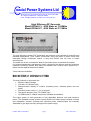
Spectrum House Finmere Road Eastbourne E.Sussex BN22 8QL UK Tel: +44 (1) 323 639974 Fax:+44 (1) 323 739654 E-mail : [email protected] Web: www.coaxialpower.com Model RFG 4K 13-27MHz 5U RF Generator INSTALLATION AND OPERATING INSTRUCTIONS CONTENTS Description Page 2 Specification Page 3 Safety Page 4 Unpacking Page 5 Installation Page 5 Front Panel Controls Page 7 Display Page 8 Interlock Indicators Page 9 Remote Control Connector Page 10 Remote Status Connections/Functions Page 11 Remote Switching and Power Control Page 12 Remote Interlock Connection/Function Page 13 Auxiliary Feedback Connection/Function Page 14 Pulse Operation Page15 Fuse Replacement Page 15 Cleaning Page 15 Warranty Page 15 CPS:Doc 20017 V1 24/01/2012 Page 1 Issue 1 24/01/2012 oaxial Power Systems Ltd Spectrum House, Finmere Road, Eastbourne, E. Sussex, BN22 8QL Tel: +44(0)1323 639974 Fax: +44(0)1323 739654 E-mail: [email protected] Web: www.coaxialpower.com High Efficiency RF Generator Model RFG4K-13, 4000 Watts at 13.56MHz Model RFG4K-27, 4000 Watts at 27.12MHz The high efficiency range of RF generators are precision units intended for scientific and industrial applications. Their robust construction using the latest in switch mode and solid-state design techniques ensure a long and trouble free life even in harsh environments. The small size of the unit makes it ideal for use where there is restricted rack space. It is recommended that the generator be used in conjunction with either a manual or automatic impedance matching network. Both types are available from Coaxial Power Systems Ltd – please see the separate brochure for details. Two models are available: Model No RFG4K-13, 4000 Watts at 13.56MHz Model Mo RFG4K-27, 4000 Watts at 27.12MHz The main features of all models are: Efficient Class-E design Full-rack, 5U (222mm) high Microprocessor display of incident (forward) power, reflected power and unit status Precision power control +/- 1% of set point. Fast pulse operation from TTL/CMOS input. 13.56MHz and 27.12MHz frequencies available as standard. The output power of each generator is fully adjustable between zero and maximum power. The feedback control system ensures that the set output power remains constant and repeatable. Incident (forward) and reflected power measurements are internally calibrated to give high accuracy throughout the power range. CPS:Doc 20017 V1 24/01/2012 Page 2 Issue 1 24/01/2012 An external voltage of 0 to 5Volts can be used to control the output. This is particularly useful in sputter coating applications where the d.c. voltage developed across the plasma dark space can be controlled rather than the RF power. General Specifications – RFG4K-13 and RFG4K-27 RF Generators Output frequency RFG4K-13, 13.56MHz. RFG4K-27, 27.12MHz. Output power 4000Watts Frequency stability Crystal controlled: 13.56MHz +/-1.4kHz 27.12MHz +/-2.7kHz Output impedance 50 output levels by utilising sample/hold technology Front panel controls Line RF on RF off Output power set Pulse/CW switch Remote switches Menu switches Front panel indicator Output connection RF power on RF power off 7/16 type/50 Front panel display Power control Analogue control system allows power or external feedback control. Output stability is +/-1% for +/-15% variation in line. VSWR capability Can withstand any VSWR at any phase angle Harmonic output Better than 40dB below fundamental Output envelope ripple Less than 1% of full amplitude Pulse operation SMA TTL input on rear panel. Minimum pulse width 40s. The external power control signal should vary the peak output from 0 to 4000W, with a pulse-on duty cycle from zero to continuous DC (100% duty cycle.) The front panel display automatically shows pulse CPS:Doc 20017 V1 24/01/2012 Vacuum fluorescent display showing: Forward (Incident) Power Reflected Power Reflected power exceed limit Remote operation Timer Cooling interlock External interlock AMN display (option) RF on/off (open collector 100mA) Incident power Reflected power RF on/off (contact closure) Interlock (contact closure) Output set 0-5Volts = 0100% Remote output set request External feedback Remote RF on/off request Cooling Forced air – air intake through front, exhaust through rear Line 380-415 VAC Three phase and Neutral 50/60Hz Size Full rack mounting 5U high 550mm deep (external connectors may protrude an extra 50mm) Weight Rear panel switches/connectors 25kg Remote connector (25-way ‘D’) Common exciter output(SMA) Common exciter input/external signal source(SMA)(max. 13dBm) Pulse input connector (SMA) Line input AMN display(option) RF output connector (N50) Front Panel -RAL7135 light grey Rear Panel - Stainless Steel Cover - Stainless Steel Remote control Accessed via rear panel 25way ‘D' type socket indicators: Page 3 Finish Environment Operating temperature: 0-35°C (-20° to +65° C storage) Standards EN61000-3-2:2006 EN6100-3-3/A2:2005 EN61326-1:2006 EN61010-1:2001 Issue 1 24/01/2012 Safety Labels Labels are provided to inform service and operating personnel of conditions that may cause personal physical injury or damage to the equipment from misuse. Caution The black exclamation point within a yellow triangle is used to highlight important service and operating instructions in this manual Electric Shock Warning A black electric flash within a yellow triangle is used to warn service and operating personnel of the prescience of unprotected contact areas which could cause severe electric shock if touched. Safety Earth Warning This symbol is used to indicate a safety earth attachment point/stud on the rear panel of the generator. This safety earth connection must be made, using a green/yellow insulated wire (14-gauge minimum) and should be as short as practical Safety earth connections inside the enclosure are identified by the warning label WARNING SAFETY EARTH DO NOT DISCONNECT CPS:Doc 20017 V1 24/01/2012 Page 4 Issue 1 24/01/2012 Unpacking Items included in carton. RF Generator. 25 Way remote connector Instruction Manual Remove all contents from carton and inspect generator for shipping damage. If there is any evidence of damage contact Coaxial Power Systems Ltd within 5 days of receipt. Installation Installation must only be performed by suitably qualified authorised personnel. This generator is designed to be fitted inside a suitable 19” rack enclosure. It should not be operated unless so fitted. Place the generator inside a suitable 19-inch enclosure which must include adequate runners for support. Ensure adequate ventilation is available at fan inlet rear panel (100mm clearance) and top and side vents (20mm clearance.) Ensure that the Mains Inlet is accessible Common Exciter Input Remote Connector RF Output Common Exciter Output Pulse Input AMN Display Input (Optional) 3 Phase Mains Input Safety Earth CPS:Doc 20017 V1 24/01/2012 Page 5 Issue 1 24/01/2012 Connect the 25-Way remote connector into socket on rear panel (factory wired to bridge external interlock) Connect the earth stud on the rear panel to a safe reliable earth using a green/yellow insulated wire (14-gauge minimum) which should be as short as practical. Screw the cable connector on to the RF Output connector on the generator. Attach the other end of the cable to a proprietary 50-Ohm resistive load capable of 4000 Watts dissipation or a load of different or complex impedance connected via a suitable RF impedance matching network. Connect the generator to the 3 Phase mains supply using the supplied mains connector. Always ensure that this connector is easily accessible . This generator operates from voltages in the range of 380V to 415V at 50 or 60Hz without the need for adjustment. Ensure Pulse/CW switch on the front panel is in the CW position Switch on line breaker on front panel. Front display, and RF Off light should illuminate. Rotate power set control to zero, press RF On. Rotate power set control towards maximum and output power should increase. Continue to rotate control to maximum and check that maximum obtainable power is correct. Press RF Off. Other rear panel connectors are: AMN Readout (Optional) – This connection is used when the capacitor positions and dc developed bias voltage are to be displayed on the generator display. This can only be used if a suitably equipped CPS automatic impedance matching network is being used. CEX Output- see later Pulse Input – see later CPS:Doc 20017 V1 24/01/2012 Page 6 Issue 1 24/01/2012 Front Panel Controls Output Set The control sets the output power, provided the unit is in “local power set” mode, meaning the remote power switch is in the down position and the remote power link is not made in the remote control connector. RF On and Off switches: The switches turn the RF output on and off, provided the unit is in “local on/off” mode, meaning the remote on switch is in the down position and the remote on/off link is not made in the remote control connector. The RF off switch is also used to reset a latched interlock condition when the unit is in “local on/off” mode, and to reset the initial “splash screen”. Remote control of RF On/Off: Operating this switch locks out the RF on and off switches on the front panel so that RF is activated by a circuit on the remote connector. CPS:Doc 20017 V1 24/01/2012 Page 7 Issue 1 24/01/2012 Remote control of RF power Operating this switch locks out the Output set control on the front panel so that RF power is controlled by a voltage on the remote connector. Power control divide by ten This simply reduces the voltage span of the output set control to allow the setting of powers up to 10% with finer resolution. Common exciter enable On units that support this facility this enables a phase-locked-loop that synchronizes the RF output to a signal on CEX-in Pulse operation enable This enables the pulse input facility. If this switch is up then RF can be rapidly gated by a “TTL” (5v logic) signal on the rear panel pulse input Display (a) The display panel shows the following information: 1.Forward RF power 2.Reflected RF power 3.Set power as a percentage 4.Timer status and progress 5.Matching network tune position 6.Matching network load position 7.Reflected power cutback warning 8.Remote control flag 9.Cooling interlock 10.External interlock Note that in the event of the RF connector interlock being open this does not generate a specific warning, however the display will switch to its alternate “interlock” layout until the connector guard is refitted and the condition reset. Menu keys: Pressing the middle menu key enters the timer setup menu CPS:Doc 20017 V1 24/01/2012 Page 8 Issue 1 24/01/2012 Interlock Indicators: Ref. Pwr: this is a warning of a high reflected power level and illuminates if the reflected power exceeds 16% of the maximum capable generator output. Cooling: this relates to over temperature of the internal power amplifier module. If illuminated, RF On will not function until module has reached a safe temperature. NB. This interlock will operate when there is : Inadequate ventilation Defective cooling. RF module fault. In the event that RF operation is interrupted the interlock state will latch until cleared by pressing RF off or removing the “Remote RF on” signal. Ext. interlock: this is operated by connecting the 25 way d connector (remote) on the rear panel pin 13 to +12V pin 25. NB. when ext. Interlock (or any other interlock) is not made, the RF Off light will not illuminate. Remote: this operates when either remote output set or remote RF On/Off request are enabled. CPS:Doc 20017 V1 24/01/2012 Page 9 Issue 1 24/01/2012 Remote Control connector The 25 way D type connector on the rear panel allows remote control of the generator. Below is a description of the various remote functions. Pin Function 1 2 3 4 5 6 7 8 9 10 11 12 13 Remote power neg. Remote power pos. Incident power Reflected power Remote RF On Ground Ground Auxiliary feedback neg. Auxiliary feedback pos. External interlock CPS:Doc 20017 V1 24/01/2012 14 15 16 17 18 19 20 21 22 23 24 25 Page 10 RF Off light Enable Remote ON Enable Aux Feedback Enable Remote power RF On light Enable True Power mode +12V out for interlock Issue 1 24/01/2012 Description Of Remote Status Connections / Functions Pin 3 Incident power. Pin 3 is an analogue output voltage 0-5 volts representing zero to maximum output power. N.B. This output can source 5mA. Pin 4 Reflected power. Pin 4 is analogue output voltage 0-5 volts representing 0-maximum output power. N.B. This output can source 5mA. Pin 14 RF Off light. Pin 9 is an open collector transistor that grounds with RF Off. This can sink 45mA 20V. Pin 19 RF On light. Pin 9 is a open collector transistor that grounds with RF On. This can sink 45mA 20V. Pin 20 +5V. This is a +5V 500mA Output. Pin 7,8 Ground CPS:Doc 20017 V1 24/01/2012 Page 11 Issue 1 24/01/2012 Description Of Remote Switching and Power control Remote RF ON Remote Output set Pin 5 RF On/Off. To enable this function connect pin 10 to a ground pin. To enable RF connect pin 5 to a ground pin, via a switch, transistor or relay. This is not latching, grounding pin 5 will switch RF On, and removing this ground will switch RF Off. N.B. Interlock functions will operate normally when using this function. Pin 15 Remote RF On/Off Switch Enable. Ground this pin to enable the remote RF On/Off control function, when it is enabled the remote indicator on the front panel is illuminated. Pins 1,2 Remote power set. To enable this function connect pin 17 to a ground pin. The set-point or control is a positive voltage in the range 0v to 5v. 0 volts gives zero output power and 5 volts gives maximum output power. Pin 17 Remote RF setpoint enable. Ground this pin to enable the remote setpoint control, when it is enabled the remote indicator on the front panel is illuminated. Pin 21 True power control enable. Ground this pin to enable “True power” operation. Note this should not be selected at the same time as remote feedback. When true power is selected the controller compensates for reflected power by raising the set power. Pins 7,8 Ground CPS:Doc 20017 V1 24/01/2012 Page 12 Issue 1 24/01/2012 Description Of Remote Interlock Connection / Function Pin 13 External Interlock. When this pin is connected to +12v it allows the generator output to be switched on. When this pin is open-circuit the “External” warning light will illuminate. Pin 25 Positive supply, +12V. Pin 7,8 Ground CPS:Doc 20017 V1 24/01/2012 Page 13 Issue 1 24/01/2012 Description Of Auxiliary feedback Connection / Function Auxiliary feedback is typically used in vacuum processes in order to control the dark space bias potential. The following drawing shows the connections to link the CPS RF generator to a CPS automatic matching network controller. Pin 9 Auxiliary feedback -ve. To enable this function connect pin 16 to a ground pin. The feedback signal should be a negative voltage in the range 0v to –5v. This function is mainly used for plasma dark-space potential (bias) control. Pin 10 Auxiliary feedback +ve. To enable this function connect pin 16 to a ground pin. Connect this pin to ground at the AMN controller Pin 16 Remote feedback enable. Ground this pin to enable the Pin1 Auxiliary feedback function. NB. When using the auxiliary feedback facility, if feedback voltage is not present then RF power will rise to maximum. On plasma systems this is often advantageous as it allows the generator to supply high power to strike plasma, then cut back to operating level as soon as plasma is struck. Other functions Pin 20 +5V. This is a +5V 500mA Output. This may be used as a power source to illuminate LEDS or power small adapter circuits or displays. Pin 6 Not Used Pin 7,8 Ground CPS:Doc 20017 V1 24/01/2012 Page 14 Issue 1 24/01/2012 Description Of 3 Phase Mains Input Connection Round connector pinout Pin 1 Reserved Pin 2 Reserved Pin 3 Live Phase 2 Pin 4 Earth Pin 5 Live Phase 3 Pin 6 Live Phase 1 Pin 7 Neutral Neutral is mandatory, failure to provide a neutral will result in damage Pulse Operation. Pulse mode is selected by the Pulse / CW switch on the front panel. The pulse signal should be TTL (active high). Minimum pulse width is 40s and with duty cycle from 1% to CW (duty cycle below 1% will cause power level to deviate from set value). The front panel displays (and remote outputs) store the last value of output power from the pulse, maintaining the reading for the duration of the off time. Cleaning To clean the surface of the generator turn off and isolate from mains, use a dry clean cloth. For heavy soiling, slightly dampen the cloth with water but always ensure that no water enters the generator. Warranty Coaxial Power Systems Ltd offer a warranty for parts and labour (if returned to factory) for 1 year from date of despatch. The warranty is invalidated if the generator has suffered inappropriate treatment i.e. excessive vibration, mechanical denting or dropping, accidental liquid spill, excessive applied voltage to remote connectors etc. Coaxial Power Systems Ltd should be notified of all warranty claims before return of equipment. CPS:Doc 20017 V1 24/01/2012 Page 15 Issue 1 24/01/2012 CPS:Doc 20017 V1 24/01/2012 Page 16 Issue 1 24/01/2012