1
Device type specific interfaces
6.2.4
34/72
Switches
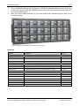
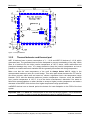
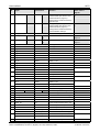
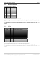
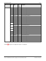
The PROFIBUS DP Slave firmware reads the position of two address switches to configure the
PROFIBUS station address.
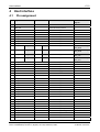
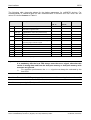
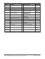
Pin
Signal
Function
46
S2_1n
Switch 2 – D1
47
S2_2n
Switch 2 – D2
48
S2_4n
Switch 2 – D4
49
S2_8n
Switch 2 – D8
50
S1_1n
Switch 1 – D1
51
S1_2n
Switch 1 – D2
52
S1_4n
Switch 1 – D4
53
S1_8n
Switch 1 – D8
54
S0_1
Switch 0 – D1
55
S0_2
Switch 0 – D2
56
S0_4
Switch 0 – D4
57
S0_8
Switch 0 – D8
Address *10
Address *1
not used
Table 16: Pin assignment address switch (NRP 10-DPS)
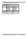
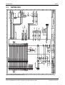
The switches are BCD coded with 10 positions. Example of a switch: COPAL Type: SA-7111TA,
see http://www.copal-electronics.com/
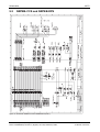
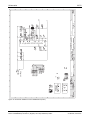
For details about the circuit for the host system see Figure 21: Schematic NRPEB-CCS and
NRPEB-DPS (Part 1) on page 62.
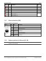
The meaning of the switches is explained in section Address switches (S1, S2) for PROFIBUS DP
on page 42.
6.2.5
SYNC
There are no signals on SYNC0 and SYNC1 because the PROFIBUS DP Slave firmware does not
generate SYNC signals.
netRAPID Chip Carrier | Design Guide
DOC111004DG04EN | Revision 4 | English | 2014-09 | Released | Public
© Hilscher, 2013-2014