1
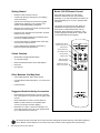
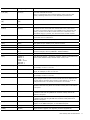
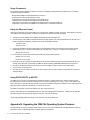
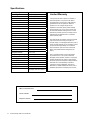
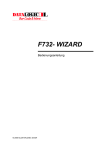
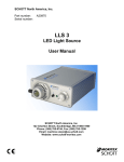
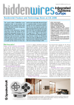
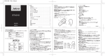
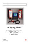
Installation and Operation
MAC ADDRESS
Model CMX-144
High Definition Audio/Video Matrix
2
Audio Authority CMX-144 User Manual
Installation and Operation Manual
Model CMX-144
High Definition Audio/Video Matrix
This document is consistent with features in firmware version 1.0
Table of Contents
Introduction . . . . . . . . . . . . . . . . . . . . . . . . . . . . . . . . . . . . . . . 4
Warnings. . . . . . . . . . . . . . . . . . . . . . . . . . . . . . . . . . . . . . . . 4
Panel Descriptions. . . . . . . . . . . . . . . . . . . . . . . . . . . . . . . . . . . 5
Getting Started. . . . . . . . . . . . . . . . . . . . . . . . . . . . . . . . . . . . . 6
Suggested Accessories. . . . . . . . . . . . . . . . . . . . . . . . . . . . . . . . . 6
Installation . . . . . . . . . . . . . . . . . . . . . . . . . . . . . . . . . . . . . . . 7
Advanced Setup and Remote Control Options . . . . . . . . . . . . . . . . . . . . . 8
Using Ethernet, RS-232, and IR. . . . . . . . . . . . . . . . . . . . . . . . . . . . 8
Operation . . . . . . . . . . . . . . . . . . . . . . . . . . . . . . . . . . . . . . . . 9
Appendix A: Serial Commands . . . . . . . . . . . . . . . . . . . . . . . . . . . . 10
Appendix B: Upgrading CMX-144 Firmware. . . . . . . . . . . . . . . . . . . . . . 12
Appendix C: Troubleshooting . . . . . . . . . . . . . . . . . . . . . . . . . . . . . 13
Appendix D: Dual 4x4 Video Matrix Applications . . . . . . . . . . . . . . . . . . . 13
Limited Warranty. . . . . . . . . . . . . . . . . . . . . . . . . . . . . . . . . . . . 14
Specifications . . . . . . . . . . . . . . . . . . . . . . . . . . . . . . . . . . . . . 14
Audio Authority and the Double-A Symbol are registered trademarks of Audio Authority Corp.
Copyright June, 2009, all rights reserved.
Harmony and Logitech are trademarks of Logitech, Inc.
Audio Authority® Corporation Lexington, Kentucky
www.audioauthority.com • 800-322-8346
Audio Authority CMX-144 User Manual
3
Introduction
The CMX-144 is the industry’s most controllable 4x4 component video matrix, featuring multiple control interfaces, a
wide variety of video and audio inputs, and a durable, attractive design sure to compliment any equipment rack or shelf.
Capable of distributing four component, analog audio, and digital audio sources to four destinations, the CMX-144 is
perfect for simple installations in mid-sized homes and small commercial applications.
Features
•
Four source input, four output matrix switcher
•
Rack mountable with included 2U rack-mount ears
•
Control via Ethernet, RS-232 serial, front panel IR,
rear panel IR, and front panel controls
Choosing a Control Interface
Most commands are available on Ethernet, IR and
RS-232, but there are differences as shown below.
RS-232
Ethernet Infrared
•
Capacitive touch front panel – easy to clean, and
no physical buttons to wear out
A/V signal switching
✔
✔
✔
✔
✔
Supports component video, analog audio, digital
coaxial audio, and digital optical audio
Power on/off
✔
•
Dimming
✔
✔
✔
•
Supports HD video resolutions up to 1080p*
Breakaway switching
✔
✔
✔(a)
•
Cross-Converts digital audio - digital coax and optical inputs are converted and output in both formats
simultaneously
Lockout (restrict)
•
Breakaway switching** – switch audio and video
independently
•
Option for composite video channel (using the
digital audio pathway, see Appendix D**)
•
Graphical web interface for basic control and status
monitoring over LAN (supports Internet Explorer 8.0
and Firefox 3.5)
•
LAN control via telnet using serial commands
•
IR codes available for use with third party control
systems including Logitech Harmony and URC.
•
Built in the USA
!
✔
✔
✔(a)
Disable front panel IR ✔
✔
✔(a)
Lock IR
✔
✔
Lock front panel keys
✔
✔
Change Ethernet
settings
✔
✔(b)
Upgrade firmware
✔
(a) These commands are available in the CCF codes,
but not available on the included 1106 remote control.
(b) If an automatic IP protocol is used to obtain an
IP address, the only direct way to obtain the new IP
address is to query the CMX-144 Ethernet settings
using RS-232.
* Many Sources do not support 1080p output on component video. When planning your system, remember
that some “1080p” sources may only offer the highest resolution on the copy protected, digital video outputs.
Similarly, some TVs are not capable of displaying a 1080p resolution, even if they accept 1080p signals.
** Breakaway switching is designed for use with component video. If the CMX-144 is used with composite video,
the composite signals will always be routed with the audio because composite video must be connected via the
digital coax pathways. Note: digital audio cannot be used if composite video is connected.
Warnings
To reduce the risk of fire or electric shock, do not expose this unit to rain or moisture.
!
The exclamation point symbol alerts users to important operating and
maintenance instructions in this booklet.
• Read this manual before installing or using this product.
• This product must be installed by qualified personnel.
• Do not open the cover—there are no user-serviceable parts inside.
• Do not expose this unit to excessive heat.
• Install only in dry, indoor locations.
• Do not obstruct the ventilation slots.
• Clean the unit only with a dry or slightly dampened soft cloth.
4
Audio Authority CMX-144 User Manual
Audio Authority CMX-144 User Manual
5
A
A
B
C
D
E
F
G
H
B
C
D
MAC ADDRESS
E
F
RS-232 Serial communication port
IR input via 3.5mm
Ethernet ID label (Mac Address)
IR input via removable screw terminal
Ethernet communication port
Component video YPbPr (do not use for composite video)
Power button with green LED indicator
Optical digital audio input
Panel Descriptions
G
I
J
K
L
M
N
O
H
I
J
K
L
Coaxial digital audio input (can also be used for composite video)
Left and right analog audio input
Source switching button for zone 2
Indicator for source 4 – illuminates blue when selected
Infrared window
Dimmer for front panel LED indicators
12V DC power input: center positive
M
N
O
Getting Started
Model 1106 IR Remote Control
•
Read this entire instruction manual.
•
Confirm that nothing is missing from your shipping
carton (see below).
•
Activate your warranty and receive future upgrade
notifications by registering your purchase on our
website: www.audioauthority.com/register.
Each CMX-144 includes one 1106 remote;
additional 1106 Remotes may be purchased
separately, or you may download the IR codes from
www.audioauthority.com. for use in programmable
IR remotes.
•
Write the serial number (see product rear panel) inside
the back cover of this manual.
•
Unpack the unit, assemble any accessories, and load
batteries into the remote.
•
Connect associated equipment (see detailed instructions in the Installation Section).
•
Connect the product to a suitable power outlet using
only the power supply furnished.
•
Perform desired setup operations via RS-232 or
Ethernet if desired (see Appendix A).
This remote control is useful in basic CMX-144
installations for switching source signals to the
main output. For advanced features, such as
breakaway audio switching or restrictions, use a
controller programmed with the IR or serial codes
for the desired features (see page 8).
SOURCE keys used to
select source input to
selected zone
ON key wakes unit
from standby mode
Carton Contents
•
Model CMX-144 High Definition Matrix
•
12-volt power supply
•
Model 1106 infrared remote control with batteries
•
Rack ears
•
User manual
OFF key enters
standby mode
DIM used to dim
the panel display
ZONE keys used to
select a zone output
Other Materials You May Need
•
Patch cables (Ethernet, RCA, and/or optical)
•
Coaxial cable and RCA terminations – for remote zone
outputs
•
Infrared receiver
Suggested Audio Authority Accessories
•
Model 1362 Up-converter/scaler: converts composite
or S-video signals to component video for legacy video
sources.
•
Model 1366 Video Converter: converts YPbPr to
RGBHV or VGA to YPbPr for incompatible video
sources or projectors and video displays.
•
Model AVP-11 or SCP-11 Cat 5 A/V Extenders: use
Cat 5 cable to extend one or all of your inputs/outputs
up to 1,000 feet from the CMX-144.
!
6
IR conflicts are likely if the CMX-144 is used in the same setting with the Audio Authority® Cat 5 Matrix (AVAtrix™).
Use a different control interface for one or both of the units, and lock out IR using the serial command [LI].
Audio Authority CMX-144 User Manual
Installation
The CMX-144 is easy to setup for simple or advanced installations. Perform the following steps.
1. Rack Mount Adapters. If the CMX-144 is to be installed
in a standard 19-inch equipment rack, remove the feet and
the cover screws adjacent to the front panel of the unit and
use them to mount Model 1192A rack adapters. Be sure to
place a spacer under the adapters at every screw location
– see illustration.
!
CAUTION! This product will be damaged if
spacers are not used on every adapter screw.
Note: Do not remove feet if using a rack shelf adapter.
2. Setting in Place. Place the CMX-144 on its shelf or in the
rack. If rack mounting, secure it to the rails with the screws
supplied with the rack adapter kits.
3. Initial Audio and Video Hookup. Connect and test
sources with a local video display in these steps. Note:
The CMX-144 may be connected using composite video
in place of coaxial digital audio. In this case, optical digital
audio cannot be used, and breakaway switching behaves
differently (See Appendix D).
IMPORTANT!
Do not mount adapters
without spacers
a. Connect each source unit to its respective set of
CMX-144 input jacks.
b. Use high quality cable and keep the runs under 6 feet if possible, especially for component video connections.
c. Connect either, but NOT BOTH optical and coaxial digital audio. Connect all the other signals available from the
source unit: component video and analog audio.
d. Connect a video display and audio system to one of the zone outputs. Use optical and/or coaxial digital audio
outputs. The CMX-144 does not convert digital audio to analog audio, so connect analog audio to the TV’s
inputs if required.
e. Turn on the sources and CMX-144 temporarily for an initial test. Select each source to the connected TV and
sound system to verify basic functions. Remove power and continue installation.
4. Zone Connections and Testing.
a. Pull good quality 75 ohm coaxial cables from the main system to each zone location and terminate cables if
necessary. Test all cables for continuity.
b. Connect the CMX-144 power supply. The unit powers up instantly. Touch the CMX-144 power button; the green
power light turns off. Touch POWER again to turn on.
c. Apply power to all sources and video displays with associated equipment. Use the 1106 remote control to verify
video and audio signal integrity of sources at each zone location.
5. Tips for Using Infrared Control.
a. If you are using standard hand-held IR remote controls, ensure correct operation by avoiding sources of light pollution such as Plasma and LCD TVs,
direct sunlight, fluorescent light, etc. Experiment with the physical placement
of the IR receiver to avoid interference.
Tip = Signal
Ring = Ground
Sleeve = +12 Volts
b. If a source of interference cannot be eliminated or avoided, use IR receivers
that block that type of interference, such as Plasma-proof or LCD-proof
receivers.
Audio Authority CMX-144 User Manual
7
Advanced Setup and Remote Control Options
Three different methods may be used for setup and matrix switching: infrared, serial (RS-232), or Ethernet. All switching
commands are available using any of these methods, but advanced configuration such as IP address settings, status
queries etc. must be performed via the serial port, or using serial commands via the Ethernet port.
1. Using a Comprehensive IR Control System. The CMX-144
can be used right out of the box; no setup is necessary. The
1106 IR remote control included with the CMX-144 is only
capable of basic functions. Comprehensive IR controllers can
use the complete CMX-144 IR code set along with the codes
of the sources and can output a macro containing source
controls and CMX-144 selection controls.
a. Patch the IR signal directly to the IR input port on the
rear panel using a standard 3.5mm cable or connecting
block. Alternatively, place a stick-on emitter or blaster
from the infrared system on the CMX-144 front panel
optical IR receiver. Do not attempt to use both methods.
b. If the CMX-144 IR codes are available from your remote
control company, download and/or activate those files.
c. A CCF file containing CMX-144 codes can be downloaded from the Audio Authority website: www.audioauthority.com/page/software. Logitech
Harmony remote controls can access the CMX-144 IR
codes in the Harmony database here: Amplifier>Audio/
Video Switch>Audio Authority>CMX-144.
d. As an alternative, follow the remote manufacturer’s
instructions to teach a learning remote control the
switching commands from the 1106 remote. Only basic
functions are available using this method.
Reset to Factory Defaults
Some circumstances require a reset to factory
default settings.
• To perform a reset, touch the SOURCE keys
for zones 1, 2, and 4 simultaneously.
• The indicators for zone 3 begin to blink.
• To cancel, touch POWER or DIM.
• To proceed with reset, touch the SOURCE
key for zone 3.
• Do not cycle power for 30 seconds while
factory default settings are being saved.
Default Settings:
•
•
•
•
•
•
•
•
All sources allowed (no restrictions)
All zones set to source 1
Optical IR sensor acitve
IP address: 192.168.000.200
Netmask: 255.255.255.000
Gateway: 0.0.0.0 (not set)
Ethernet speed: auto
Web refresh: off
2. Using the RS-232 Port. System controllers and PCs can send all setup and control commands via the RS-232 serial
port and receive feedback.
a. Important: if a PC is connected directly to the CMX-144 RS-232 port use standard serial cable.
b. This control method is capable of performing all commands including firmware upgrade (See Appendix B).
c. See Appendix A for details on using serial commands.
3. Using the Ethernet Port. Use a telnet client or terminal program on a Mac or PC to send most setup and control
commands through the Ethernet port on the CMX-144.
• Connect a PC directly to the Ethernet port using a standard Ethernet patch cable. If the PC does not have
automatic MDI-X capability, use a crossover cable.
• Connect a PC or other IP control device through an Ethernet hub or switch using a standard patch cable.
• Follow instructions in Appendix A “Setup Using Ethernet”
• Ethernet cannot be used to upgrade firmware; use RS-232. All other commands are available using Ethernet.
4. Using the Web Interface. Basic CMX-144 switching functions are available when using a web browser on a PC
connected directly to the CMX-144 Ethernet port, or through a hub, local area network or even through the Internet.
• To access the unit’s Web-based Interface, launch IE 8.0 or Firefox 3.5, and enter the CMX-144 IP address.
• The web interface is loaded. Click POWER, SOURCE, and DIM similar to the front panel.
• Enable web refresh to monitor the CMX-144 (see Appendix A). When the CMX-144 receives a command from
any other source (e.g. IR, or RS-232), the changes are automatically reflected on the front panel and in the
graphical web interface. (One exception is the DIM key, which does not produce a change in the brightness of
the source indicators on the graphical web interface.)
8
Audio Authority CMX-144 User Manual
Operation
1. Front Panel Keys. The front panel is operated by touching the sensitive “key” areas: POWER, SOURCE, and DIM.
• Touch POWER to turn the unit on or off (low power mode).
• Each time you touch a SOURCE key, the CMX-144 switches to the next available source.
• Any restricted zones are skipped (if source 1 is restricted other zones select source 2, 3, 4, and then back to 2).
• The power button puts the unit in “low power mode”. Wake the unit by sending any valid IR command, web
interface command, serial command, or touching the POWER key.
• Touch the DIM key to change the front panel indicator brightness. Three levels of brightness and off are available. The POWER button dims in off mode, but does not turn off completely except in low power mode.
2. Model 1106 Remote Control. The 1106 enables all functions of the front panel including discrete on and off. Note:
if the CMX-144 receives an IR command via the rear panel IR input, the front panel IR receiver is automatically
disabled until power is manually removed from the unit or the IR is reset via serial or Ethernet. (See Appendix A).
• Press OFF to enter standby mode.
• Press any key to wake the unit from standby mode.
• Press a ZONE key and then a SOURCE key to switch sources. The other zone indicators dim while source
selection is taking place. If the ZONE key is pressed again, the selection is cancelled. If a SOURCE key is
pressed without first pressing a ZONE key, the unit does not switch sources.
• The zone stays active for 10 seconds after the ZONE key is pressed. If no source key is pressed, the unit
returns to a neutral state. The user must press a ZONE key to switch sources.
Advanced Operation Behavior
Controlling the CMX-144 via serial, Ethernet, or IR controllers enables all basic functions above, plus the advanced
features listed below. Note that new settings are saved every 30 seconds. If the unit is powered off before the 30 second
auto-save, those settings will be lost when the unit powers on. Use the manual save command [S] to save after making
permanent changes.
1. Lockout (Source Restriction).
• Any user can “lockout” other zones from viewing the currently selected source.
• When a user sends a lockout command, the video blinks once to indicate that lockout has been implemented.
• If any other zones are viewing the source when it becomes locked, they are switched to the next allowed
source.
• The source remains locked to the zone for five hours or until that user cancels the lockout.
• When an attempt is made to view the locked source from front panel controls or graphical web interface, the
CMX-144 skips the locked source and selects the next allowed source.
• When a source is restricted while in breakaway mode (see breakaway audio switching below), the audio is
matched to the video of the source. Example: if zone 1 selects input 1 video and input 2 audio, and then sends
a lockout command, the CMX-144 switches to input 1 audio and video and locks out other zones.
• When a user tries to select a restricted source via serial or Ethernet, the component video blinks once and the
feedback string (RESTR) is returned on the serial port.
2. Breakaway Audio Switching. Audio and video switched independently. See Appendix A.
• Advanced control methods can switch audio independent of video. Example: the user is watching a sports
event (Source 1, satellite TV) and wants to listen to radio coverage (Source 2, internet radio).
• If the CMX-144 is used with composite video, the composite signals will always be routed with the audio
because composite video must be connected via the digital coax pathways. See Appendix D for details.
• The CMX-144 can be used with both component and composite video, using the Breakaway switching feature
to control Component and composite video signals separately, enabling the CMX-144 to behave as two 4x4
video matrix switchers. See Appendix D for details.
Audio Authority CMX-144 User Manual
9
Appendix A: Serial Commands
Description
Command Structure
Commands can be used at any time via RS-232 or Ethernet
to change the CMX-144 settings. Certain commands, such as
[FLASH] to upgrade firmware, can be used only via RS-232.
See page 4 for details.
Channel switch – switches a
source input to a zone output.
There are many possible
modifiers, such as V for video, A
for a audio, X for all.
.
[C,(Z# or X),(V),(A),I#];
V, A, optional; either Z# or
X is required
•
All serial commands require opening and closing brackets
“[ ]” but do not require any periods, spaces, or commas.
[P,(F or N)]; F or N are
required
•
Commands can be sent in any order: [RPZ1] = [R, Z1, P]
Power switch – switches the
unit into low power or normal
operating modes.
•
Enter a line feed and carriage return after each command.
Dim – adjust indicator level.
[I,#]
•
ASCII codes not specified are ignored (i.e. control codes,
unused alphanumeric characters, etc.).
Restrict – locks out other zones
from viewing the source selected
by a particular zone.
[R,(P),Z#,I#]; P optional
Allow – removes a restriction on
a source attached to a zone.
[A,(P),Z#,I#]
Query – V=version, X=all,
Z=zone (see p12 for more info).
[?,(V|X|Z#)]
Front Panel IR – disable/enable.
[IRFD], [IRFE]
IR – lock/unlock.
[LI][UI]
Panel keyboard – lock/unlock.
[LK][UK]
Save – force a save of the
current settings to memory.
[S]
Help – display list of commands.
[H], [H,#]
Ethernet – view settings.
[EV,1], [EV,2]
bash-3.2$ telnet 192.168.0.234 10001
Trying 192.168.0.234...
Connected to CA84AFD.privatelan.com.
Escape character is ‘^]’.
Ethernet – set IP address.
[EI ###.###.###.###]
[?,X]
(Z1,I2)
(Z2,I2)
(Z3,I1)
(Z4,I4)
Ethernet – set default gateway.
[EG ###.###.###.###]
Ethernet – Set the subnet mask.
[EN ###.###.###.###]
Refresh rate – Set the web page
auto-refresh rate.
[ET##]
Ethernet DHCP – Enable DHCP.
[ED,#]
Ethernet BOOTP – Enable BOOTP.
[EB,#]
Ethernet AUTOIP – Enable
AUTOIP.
[EA,#]
Default RS-232 Port Settings
Transfer Rate
Data Bits
Stop Bits
Parity
Flow Control or Data Flow
Character type
Interface connector
DB-9 Electrical rating
DB-9 Pin-out
9600 bps
8
1
None
None
ASCII
DB-9
Pins 2 and 3, ±15 VDC
Pin 2, Tx
Pin 3, Rx
Pin 5, Ground
Shell, Ground
Example Command Line Telnet Session
Log on
Query
switching
status
Switch Zone
3 to Input 2
Ethernet
settings,
mode 2
Help
(table of
contents)
[EV1]
ETHERNET 1:
IP ADDRESS: 192.168.0.200
NET MASK..: 255.255.255.0
GATEWAY...: 0.0.0.0
[H]
HELP:
COMMON..:
OTHER...:
ETH 1...:
ETH 2...:
SYMBOLS.:
EXAMPLES:
[H1]
[H2]
[H3]
[H4]
[H5]
[H6]
Lock IR
[LI]
(LI)
Ethernet – set LAN speed.
[ES,#]
Lock
keyboard
[LK]
(LK)
Ethernet – Web interface enable.
[EW,#]
Firmware – Upgrade firmware.
[FLASH]
Save settings
10
[C,Z3,I2]
(Z3,I2)
[S]
(S)
Audio Authority CMX-144 User Manual
Example Command(s)
Example Output
Result
[C,Z1,I1]
[C,Z1,A,I2]
(Z1,I1)
(Z1,A,I2)
Zone 1 is connected to source audio and video 1 provided that no other
zone has restricted this source.
Zone 1 is connected to source 2 audio and the video is left as it was
before, assuming that source 2 is not restricted by another zone.
[P,F]
[P,N]
(P,F)
(P,N)
Switch into low power mode, switch back into normal operating mode.
[I,2]
(I,2,35)
Front panel zone indicators dim to level 2. Values=1-3 and 0=off.
[R,Z1]
[R,Z1,P]
(Z1,R)
(Z1,R,P)
Zone 1 audio is switched to match the input video source that is currently
selected; all other zones that have selected this source, either audio
or video, are forced to select the next available source (both audio and
video); no other zone is able to select this source in the future. If no
permanent flag (P) is present, the restriction times out after 5 hours.
[A,Z1]
(Z1,A)
Removes the restriction that prevents other zones from selecting the
source that zone1 is attached to.
[?,Z1]
(Z1,I1)
Display the requested output (see p12 for more info).
[IRFE]
(IRFE)
Rear panel IR input disabled, front panel IR enabled.
[LI]
(L,I)
Ignores all IR input.
[LK]
(L,K)
Ignores input from front panel key presses.
[S]
(S)
(S...)
Save all of the current status setting to memory. If an Ethernet setting
has been changed, wait for (FINISHED...PLEASE REBOOT).
[H3]
HELP 3:...
Display command syntax. Valid numbers are 1-6, see Example on the left.
[EV,2]
AUTOIP.: 0
BOOTP..: 0
DHCP...: 0
SPEED..: AUTO
WEB ENA: 1
WEB RFR: 0
View Ethernet settings – IP address, netmask, gateway, webrefresh timer,
DHCP enable, BOOTP enable, AUTOIP enable. 0=off, 1=on.
[EI 192.168.000.200]
(IP 192.168.0.200)
Set the Ethernet IP address. Each 3 digit part must contain all 3 digits;
for example, to enter a 1 use 001.
[EG 192.168.001.010]
(GW 192.168.1.10)
Set the Ethernet default gateway. Each 3 digit part must contain all 3
digits; for example, to enter a 1 use 001.
[EN 255.255.255.000]
(NM 255.255.255.0)
Set the Ethernet subnet mask. Each 3 digit part must contain all 3 digits;
for example, to enter a 1 use 001.
[ET03]
(ET,3)
Set the web page auto-refresh time. When viewing the current status web
page, changes made by other control methods will not be displayed until
the web page is refreshed. Auto-refresh is off by default (0). It can be
changed here from 3-10 seconds, 20 seconds or 30 seconds.
[ED,1]
(ED,1)
Enable or disable ethernet DHCP. A setting of 1 enables, a setting of 0
disables. Note that using DHCP can introduce a delay while an IP address
is acquired.
[EB,1]
(EB,1)
Enable or disable ethernet BOOTP. A setting of 1 enables, a setting of
0 disables. Note that using BOOTP can introduce a delay while an IP
address is acquired.
[EA,1]
(EA,1)
Enable or disable Ethernet AUTOIP. A setting of 1 enables, a setting of
0 disables. Note that using AUTOIP can introduce a delay while an IP
address is acquired.
[ES,1]
(ES,1)
Changes LAN speed. 0=Auto, 1=10 MBPS half duplex, 2=10 MBPS full
duplex, 3=100 MBPS half duplex, 4=100 MBPS full duplex.
[EW,1]
(EW,1)
Enables/disables web interface.
[FLASH]
(FLASH)
Begin firmware upgrade. See Upgrading Firmware (Appendix B).
Audio Authority CMX-144 User Manual
11
Query Commands
The [?] serial command displays the table of zone/source mappings including restrictions. Specific query commands
include the following characters:
Z# represents ZONE # and S# represents input source #.
X represents the currently selected input source
V represents the currently selected video source (break-away)
A represents the currently selected audio source (break-away)
T represents a source that is unavailable to be selected due to a temporary restriction.
P represents a source that is unavailable to be selected due to a permanent restriction.
Setup for Ethernet Control
There are several ways to set up the CMX-144 for use with an IP capable controller using a PC. Either allow it to acquire*
an IP address using DHCP, BOOTP, or AUTOIP, or change the IP address manually, as follows:
1. Change the PC’s IP address to an available IP address such as 192.168.0.001.
2. Connect the PC to the CMX‑144 via RS‑232 or Ethernet (see page 8). Use a terminal application for RS-232; use a
telnet client/terminal application for Ethernet and enter the default IP address:
192.168.0.200
and port: 10001
3. Change the IP address as shown below, filling in the appropriate values for the network where the CMX‑144 will
reside. Note that you must enter twelve digits (e.g. enter 001 for the numeral 1, as follows: 255.255.255.001).
[EIxxx.xxx.xxx.xxx]
4. In the same way, assign subnet mask and (if necessary) assign default gateway.
[NMxxx.xxx.xxx.xxx]
[GWxxx.xxx.xxx.xxx]
5. Enter [S] to save the changes, and allow about 20 seconds for the Ethernet port to be reprogrammed with the new
settings. If the serial port is connected, the CMX-144 sends the string (FINISHED). Manually disconnect power.
6. Disconnect the Ethernet cable from the PC and connect the CMX-144 to the network (use a patch cable).
7. Connect power to the CMX-144.
8. The CMX-144 is now ready to use with an IP control system. Use the new IP address to view CMX-144 status and
change settings*.
Using DHCP, BOOTP, or AUTOIP
The CMX-144 can use one of the automatic IP address protocols to configure itself for any Ethernet network. Follow
the steps above, but instead of performing steps 3 and 4, send the command [ED1], [EB1], or [EA1] and continue with
step 5. After step 7 it may take several seconds to acquire an IP address using DHCP or BOOTP. In the case of AUTOIP it
may take longer to receive the IP address, up to about 15 seconds.
The CMX-144 requests a dynamic IP address only upon physical power on.
The only way to discover the IP address directly is to query the settings via the RS-232 port. If RS-232 is not available,
use other network tools and the MAC address to learn the unit’s new IP address.
* Each CMX-144 MAC address is shown on the rear panel near the Ethernet port.
Appendix B: Upgrading the CMX-144 Operating System Firmware
The latest firmware version is available to download to your PC from www.audioauthority.com/page/software. Follow the
instructions online or call Audio Authority Technical Support for assistance.
12
Audio Authority CMX-144 User Manual
Appendix C: Troubleshooting
Symptom
Causes and Solutions
No video
• Check that the correct input is selected on the zone
• Check that the video is connected to the correct Y Pb Pr inputs on the TV
• Check cables for damage
No analog audio
• Connect analog audio to the inputs and from the outputs of the CMX-144 – digital audio does not
produce sound on the analog audio outputs.
No digital audio
• If composite video is connected to any digital audio jacks, both digital audio pathways are disabled
Front panel
blinks
• Front panel is locked – use serial or IR commands to unlock the keyboard
IR does not
function properly
• If rear panel IR has been used, the optical IR receiver is automatically disabled – enable the
optical IR receiver via serial command [IRFE] or manually disconnect and connect power
• IR interference such as LCD/Plasma screen, fluorescent lights, space heater, sunlight
• Eliminate sources of IR interference and use Plasma-proof and/or LCD-proof IR receivers
• Experiment with relocating the IR receiver
• Incompatible IR receivers – use only 12 volt, three-wire receivers (see page 7)
Does not
respond to
RS‑232
• CMX-144 commands not stored in remote control system – See Appendix A
• Wrong type of RS-232 cable – See specifications in Appendix A for proper cable pin-out
• Incorrect settings in software – See specifications in Appendix A
Ethernet port
does not respond
• IP address has been changed – reset to factory defaults, or use serial command via RS-232 port
to set new IP address (Appendix A)
Appendix D: Dual 4x4 Video Matrix Applications
The CMX-144 can be used with both component and composite video simultaneously. Using the breakaway switching
feature, the resulting configuration behaves like two 4x4 video matrix switchers in one cabinet.
•
Add four composite video sources connected to the digital audio inputs.
•
The composite video outputs can be connected to standard definition video monitors (shown below), or they can be
connected to a composite video input on the HDTVs.
•
The component video signals have no audio channels switched with them, while the composite video signals do
COMPOSITE
VIDEO SOURCES
STANDARD RESOLUTION
VIDEO DISPLAYS
CMX-144
COMPONENT
VIDEO SOURCES
HDTVS WITH
COMPONENT
VIDEO INPUTS
Audio Authority CMX-144 User Manual
13
Specifications
Video Signal Type:
Component (YPbPr)
Alternate Type:
Composite (digital audio jacks)
Resolution Formats:
480i/p, 540i/p, 720p, 1080i/p
Input/Output Impedance:
75 ohms
Input Ground Isolation:
No
Video Gain:
1
Gain Accuracy:
2%
3dB Bandwidth:
180MHz
Input Coupling:
AC
S/N Ratio:
65dB
Digital Audio In/Out:
Coaxial + optical in/out
Input Impedance:
75 ohms/50K ohms
Min Load Impedance:
75 ohms/10K ohms
Multi-channel Digital Audio:
Yes
Frequency Response:
10-50KHz
S/N Ratio:
75dB
THD+Noise:
0.02%
Crosstalk:
-70dB
Agency Approvals:
FCC
DC Input Connector:
5.5 X 2.1mm
DC Input Voltage/Polarity:
12V center positive
Max DC Input Current:
350mA
Power Supply:
PN: 571-013, 12V DC 1A
Heat Output:
22 BTU/hr
Size w/o feet (H-W-D, in.):
3.5 x 16.7 x 9
Warranty:
One year replacement
Agency Approvals:
FCC
Accessories Included:
IR remote with batteries,
AC adapter, rack ears, manual
CMX-144 Serial Number
Custom Installer
Telephone Number
14
Audio Authority CMX-144 User Manual
Limited Warranty
If this product fails due to defects in materials or
workmanship within one year from the date of
the original sale to the end-user, Audio Authority
guarantees that we will replace the defective
product at no cost. Freight charges for the
replacement unit will be paid by Audio Authority
(Ground service only). A copy of the invoice from
an Authorized Reseller showing the item number
and date of purchase (proof-of-purchase) must be
submitted with the defective unit to constitute a
valid in-warranty claim.
Units that fail after the warranty period has expired
may be returned to the factory for repair at a
nominal charge, if not damaged beyond the point of
repair. All freight charges for out-of-warranty returns
for repair are the responsibility of the customer.
Units returned for repair must have a Customer
Return Authorization Number assigned by the
factory.
This is a limited warranty and is not applicable
for products which, in our opinion, have been
damaged, altered, abused, misused, or improperly
installed. Audio Authority makes no other warranties either expressed or implied, including limitation
warranties as to merchantability or fitness for
a particular purpose. Additionally, there are no
allowances or credits available for service work or
installation performed in the field by the end user.
Audio Authority CMX-144 User Manual
15
2048 Mercer Road, Lexington, Kentucky 40511-1071 USA
Phone: 859-233-4599 • Fax: 859-233-4510
Customer Toll-Free USA & Canada: 800-322-8346
www.audioauthority.com • [email protected]
v 1.1
752-585
10/11