1
Helios Ventilatoren
INSTALLATION AND OPERATING INSTRUCTIONS
Nr. 82 600 UK
Central ventilation units for ceiling installation
KWL EC 700 D Pro / WW
KWL EC 1400 D Pro / WW
KWL EC 2000 D Pro / WW
with heat recovery and EC technology for
ventilation
ENGLISH
This product contains batteries or accumulators. According to the German Battery Act (BattG), we are obliged to point out the following:
Batteries and accumulators must not be disposed of in household waste. You are legally obligated to return used batteries and accumulators. You can return batteries to a community collection point or return them to the place where you bought them free of charge.
Batteries or accumulators that contain harmful substances are labelled with the symbol of a crossed-out waste bin. The chemical symbol of the harmful substance is
specified below the waste bin symbol.
Cd for Cadmium, Pb for Lead and Hg for Mercury
Please think of the environment, you can make a significant contribution to the environmental protection by returning batteries and accumulators!
Installation and operating instructions
Central ventilation units KWL EC 700/1400/2000 D Pro / WW
UK
Table of Contents
CHAPTER 1. GENERAL INSTALLATION AND OPERATING INSTRUCTIONS . . . . . . . . . . . . . . . . . . . . . . . . . . . .page 2
1.0
Important information . . . . . . . . . . . . . . . . . . . . . . . . . . . . . . . . . . . . . . . . . . . . . . . . . . . . . . . . . . . . . . . . . .page 2
1.1
Warning and safety instructions . . . . . . . . . . . . . . . . . . . . . . . . . . . . . . . . . . . . . . . . . . . . . . . . . . . . . . . . . .page 2
1.2
Warranty claims – Exclusion of liability . . . . . . . . . . . . . . . . . . . . . . . . . . . . . . . . . . . . . . . . . . . . . . . . . . . . .page 2
1.3
Certificates . . . . . . . . . . . . . . . . . . . . . . . . . . . . . . . . . . . . . . . . . . . . . . . . . . . . . . . . . . . . . . . . . . . . . . . . .page 2
1.4
Receipt . . . . . . . . . . . . . . . . . . . . . . . . . . . . . . . . . . . . . . . . . . . . . . . . . . . . . . . . . . . . . . . . . . . . . . . . . . . .page 2
1.5
Storage . . . . . . . . . . . . . . . . . . . . . . . . . . . . . . . . . . . . . . . . . . . . . . . . . . . . . . . . . . . . . . . . . . . . . . . . . . . .page 2
1.6
Shipping . . . . . . . . . . . . . . . . . . . . . . . . . . . . . . . . . . . . . . . . . . . . . . . . . . . . . . . . . . . . . . . . . . . . . . . . . . .page 2
1.7
Application – Operation . . . . . . . . . . . . . . . . . . . . . . . . . . . . . . . . . . . . . . . . . . . . . . . . . . . . . . . . . . . . . . . .page 2
1.8
Function and operation modes . . . . . . . . . . . . . . . . . . . . . . . . . . . . . . . . . . . . . . . . . . . . . . . . . . . . . . . . . .page 3
1.9
Performance data . . . . . . . . . . . . . . . . . . . . . . . . . . . . . . . . . . . . . . . . . . . . . . . . . . . . . . . . . . . . . . . . . . . .page 3
1.10 Heat systems . . . . . . . . . . . . . . . . . . . . . . . . . . . . . . . . . . . . . . . . . . . . . . . . . . . . . . . . . . . . . . . . . . . . . . . .page 3
1.11 Technical data . . . . . . . . . . . . . . . . . . . . . . . . . . . . . . . . . . . . . . . . . . . . . . . . . . . . . . . . . . . . . . . . . . . . . . .page 4
CHAPTER 2. INSTALLATION . . . . . . . . . . . . . . . . . . . . . . . . . . . . . . . . . . . . . . . . . . . . . . . . . . . . . . . . . . . . . . . . .page 5
2.0
Assembly . . . . . . . . . . . . . . . . . . . . . . . . . . . . . . . . . . . . . . . . . . . . . . . . . . . . . . . . . . . . . . . . . . . . . . . . . . .page 5
2.1
Ceiling installation . . . . . . . . . . . . . . . . . . . . . . . . . . . . . . . . . . . . . . . . . . . . . . . . . . . . . . . . . . . . . . . . . . . .page 5
2.2
Condensation outlet . . . . . . . . . . . . . . . . . . . . . . . . . . . . . . . . . . . . . . . . . . . . . . . . . . . . . . . . . . . . . . . . . . .page 6
2.3
Flange connection / adapter pieces . . . . . . . . . . . . . . . . . . . . . . . . . . . . . . . . . . . . . . . . . . . . . . . . . . . . . . .page 6
2.4
Air ducting, Ventilation circuit . . . . . . . . . . . . . . . . . . . . . . . . . . . . . . . . . . . . . . . . . . . . . . . . . . . . . . . . . . . .page 6
2.5
Unit insulation . . . . . . . . . . . . . . . . . . . . . . . . . . . . . . . . . . . . . . . . . . . . . . . . . . . . . . . . . . . . . . . . . . . . . . .page 7
2.6
Electrical connection . . . . . . . . . . . . . . . . . . . . . . . . . . . . . . . . . . . . . . . . . . . . . . . . . . . . . . . . . . . . . . . . . .page 7
CHAPTER 3. FUNCTIONAL DESCRIPTION . . . . . . . . . . . . . . . . . . . . . . . . . . . . . . . . . . . . . . . . . . . . . . . . . . . . . .page 8
3.0
Unit overview . . . . . . . . . . . . . . . . . . . . . . . . . . . . . . . . . . . . . . . . . . . . . . . . . . . . . . . . . . . . . . . . . . . . . . . .page 8
3.1
Functional diagram . . . . . . . . . . . . . . . . . . . . . . . . . . . . . . . . . . . . . . . . . . . . . . . . . . . . . . . . . . . . . . . . . . .page 8
3.2
Functions . . . . . . . . . . . . . . . . . . . . . . . . . . . . . . . . . . . . . . . . . . . . . . . . . . . . . . . . . . . . . . . . . . . . . . . . . . .page 9
3.2.1 Internal pre-heater . . . . . . . . . . . . . . . . . . . . . . . . . . . . . . . . . . . . . . . . . . . . . . . . . . . . . . . . . . . . . . . . . . . .page 9
3.2.2 Heat exchanger frost-protection . . . . . . . . . . . . . . . . . . . . . . . . . . . . . . . . . . . . . . . . . . . . . . . . . . . . . . . . .page 9
3.2.3 Hot water heater . . . . . . . . . . . . . . . . . . . . . . . . . . . . . . . . . . . . . . . . . . . . . . . . . . . . . . . . . . . . . . . . . . . .page 10
3.2.4 Frost-protection Hot water heater . . . . . . . . . . . . . . . . . . . . . . . . . . . . . . . . . . . . . . . . . . . . . . . . . . . . . . .page 10
3.2.5 Frost-protection for downstream hot water heater . . . . . . . . . . . . . . . . . . . . . . . . . . . . . . . . . . . . . . . . . .page 10
3.2.6 Thermal comfort temperature . . . . . . . . . . . . . . . . . . . . . . . . . . . . . . . . . . . . . . . . . . . . . . . . . . . . . . . . . .page 11
3.2.7 Cover flaps . . . . . . . . . . . . . . . . . . . . . . . . . . . . . . . . . . . . . . . . . . . . . . . . . . . . . . . . . . . . . . . . . . . . . . . .page 11
3.2.8 RUN output . . . . . . . . . . . . . . . . . . . . . . . . . . . . . . . . . . . . . . . . . . . . . . . . . . . . . . . . . . . . . . . . . . . . . . . .page 11
3.2.9 External contact . . . . . . . . . . . . . . . . . . . . . . . . . . . . . . . . . . . . . . . . . . . . . . . . . . . . . . . . . . . . . . . . . . . . .page 11
3.2.10 Fire mode . . . . . . . . . . . . . . . . . . . . . . . . . . . . . . . . . . . . . . . . . . . . . . . . . . . . . . . . . . . . . . . . . . . . . . . . .page 11
3.2.11 Condensate contact . . . . . . . . . . . . . . . . . . . . . . . . . . . . . . . . . . . . . . . . . . . . . . . . . . . . . . . . . . . . . . . . .page 11
3.2.12 Monozone “manual” . . . . . . . . . . . . . . . . . . . . . . . . . . . . . . . . . . . . . . . . . . . . . . . . . . . . . . . . . . . . . . . . .page 11
3.2.13 Monozone „ auto“ . . . . . . . . . . . . . . . . . . . . . . . . . . . . . . . . . . . . . . . . . . . . . . . . . . . . . . . . . . . . . . . . . . .page 11
3.2.14 Multizone . . . . . . . . . . . . . . . . . . . . . . . . . . . . . . . . . . . . . . . . . . . . . . . . . . . . . . . . . . . . . . . . . . . . . . . . . .page 12
3.2.15 Automatic Bypass . . . . . . . . . . . . . . . . . . . . . . . . . . . . . . . . . . . . . . . . . . . . . . . . . . . . . . . . . . . . . . . . . . .page 12
3.2.16 Demand-driven regulation of ventilation units through CO2- and humidity sensors . . . . . . . . . . . . . . . . . . .page 12
3.2.17 Vent calibration . . . . . . . . . . . . . . . . . . . . . . . . . . . . . . . . . . . . . . . . . . . . . . . . . . . . . . . . . . . . . . . . . . . . .page 13
CHAPTER 4. CONTROLLER . . . . . . . . . . . . . . . . . . . . . . . . . . . . . . . . . . . . . . . . . . . . . . . . . . . . . . . . . . . . . . . . .page 14
4.0
Surface-mounted controller with touch screen . . . . . . . . . . . . . . . . . . . . . . . . . . . . . . . . . . . . . . . . . . . . . .page 14
4.1
Operating menu / Parameter settings via touch screen . . . . . . . . . . . . . . . . . . . . . . . . . . . . . . . . . . . . . . .page 14
CHAPTER 5. DIMENSIONS / CHARACTERISTIC CURVES . . . . . . . . . . . . . . . . . . . . . . . . . . . . . . . . . . . . . . . .page 23
5.0
Dimensions . . . . . . . . . . . . . . . . . . . . . . . . . . . . . . . . . . . . . . . . . . . . . . . . . . . . . . . . . . . . . . . . . . . . . . . .page 23
5.1
Adjustment . . . . . . . . . . . . . . . . . . . . . . . . . . . . . . . . . . . . . . . . . . . . . . . . . . . . . . . . . . . . . . . . . . . . . . . .page 23
5.2
Minimum requirements for starting up . . . . . . . . . . . . . . . . . . . . . . . . . . . . . . . . . . . . . . . . . . . . . . . . . . . .page 24
CHAPTER 6. SERVICE AND MAINTENANCE . . . . . . . . . . . . . . . . . . . . . . . . . . . . . . . . . . . . . . . . . . . . . . . . . . .page 24
6.0
Service and maintenance . . . . . . . . . . . . . . . . . . . . . . . . . . . . . . . . . . . . . . . . . . . . . . . . . . . . . . . . . . . . . .page 24
6.1
Removing/cleaning cross counter flow heat exchanger . . . . . . . . . . . . . . . . . . . . . . . . . . . . . . . . . . . . . . .page 24
6.2
Filter change . . . . . . . . . . . . . . . . . . . . . . . . . . . . . . . . . . . . . . . . . . . . . . . . . . . . . . . . . . . . . . . . . . . . . . .page 25
6.3
Reset function . . . . . . . . . . . . . . . . . . . . . . . . . . . . . . . . . . . . . . . . . . . . . . . . . . . . . . . . . . . . . . . . . . . . . .page 26
6.4
Condensation outlet in the unit . . . . . . . . . . . . . . . . . . . . . . . . . . . . . . . . . . . . . . . . . . . . . . . . . . . . . . . . .page 27
6.5
Terminal box with isolator/main switch . . . . . . . . . . . . . . . . . . . . . . . . . . . . . . . . . . . . . . . . . . . . . . . . . . . .page 27
6.6
Accessories . . . . . . . . . . . . . . . . . . . . . . . . . . . . . . . . . . . . . . . . . . . . . . . . . . . . . . . . . . . . . . . . . . . . . . . .page 27
6.7
Error messages / Alarms . . . . . . . . . . . . . . . . . . . . . . . . . . . . . . . . . . . . . . . . . . . . . . . . . . . . . . . . . . . . . .page 27
CHAPTER 7. WIRING DIAGRAM OVERVIEW . . . . . . . . . . . . . . . . . . . . . . . . . . . . . . . . . . . . . . . . . . . . . . . . . . .page 28
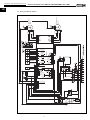
7.0
Wiring diagram SS-1006 . . . . . . . . . . . . . . . . . . . . . . . . . . . . . . . . . . . . . . . . . . . . . . . . . . . . . . . . . . . . . .page 28
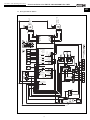
7.1
Wiring diagram SS-1007 . . . . . . . . . . . . . . . . . . . . . . . . . . . . . . . . . . . . . . . . . . . . . . . . . . . . . . . . . . . . . .page 29
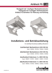
7.2
Wiring diagram SS-1008 . . . . . . . . . . . . . . . . . . . . . . . . . . . . . . . . . . . . . . . . . . . . . . . . . . . . . . . . . . . . . .page 30
7.3
Wiring plan KWL EC 700 D . . . . . . . . . . . . . . . . . . . . . . . . . . . . . . . . . . . . . . . . . . . . . . . . . . . . . . . . . . . .page 31
7.4
Wiring plan KWL EC 1400 D . . . . . . . . . . . . . . . . . . . . . . . . . . . . . . . . . . . . . . . . . . . . . . . . . . . . . . . . . . .page 32
7.5
Wiring plan KWL EC 2000 D . . . . . . . . . . . . . . . . . . . . . . . . . . . . . . . . . . . . . . . . . . . . . . . . . . . . . . . . . . .page 33
1
Installation and operating instructions
Central ventilation units KWL EC 700/1400/2000 D Pro / WW
UK
1.0 Important information
CHAPTER 1
To ensure safety and correct operation please read and observe the following instructions carefully before proceeding.
Important information is specified in the maintenance section on filter changes and necessary cleaning and maintenance activities. The user usually accomplishes maintenance work. The chapter “Installation” with important installation
tips and basic unit adjustments is intended for the specialised installer.
The electrical connection must be fully isolated from the supply up to the final assembly!
The planning office provides the planning documents necessary for system calculations. Additional information can be
requested ex works. Keep the installation and operating instructions as a reference at the device. After the final assembly, the document must be handed out to the operator (tenant/owner).
GENERAL INSTALLATION
AND OPERATING
INSTRIUCTIONS
WARNING
1.1
Warning and safety instructions
The accompanying symbol is a safety-relevant prominent warning symbol. All safety regulations and/or
symbols must be absolutely adhered to, so that any dangerous situation is avoided.
1.2
Warranty claims – Exclusion of liability
If the preceding instructions are not observed, all warranty claims and accommodation treatment are excluded. This
also applies to any liability claims extended to the manufacturer.
The use of accessories not offered or recommended by Helios is not permitted. Potential damages are not covered by
warranty.
1.3
Certificates
If the product is installed correctly and used to its intended purpose, it conforms to all applicable European Standards
at its date of manufacture.
1.4
Receipt
The delivery contains one of the following unit types:
KWL EC 700 D Pro
Order No. 4171
KWL EC 700 D Pro WW
Order No. 4172
KWL EC 1400 D Pro
Order No. 4173
KWL EC 1400 D Pro WW
Order No. 4174
KWL EC 2000 D Pro
Order No. 4175
KWL EC 2000 D Pro WW
Order No. 4176
The scope of delivery also includes:
1x Duct temperature sensor (already connected to terminal box)
1x Surface-mounted controller (with touchscreen) incl. room sensor and connection cable (5 m)
Please check delivery immediately on receipt for accuracy and damage. If damaged, please notify carrier immediately.
In case of delayed notification, any possible claim may be void.
1.5
Storage
When storing for a prolonged time the following steps are to be taken to avoid damaging influences:
Protection by dry, air- dustproof packing (plastic bags with drying agent and moisture indicators). The storage place
must be water-proof, vibration-free and free of temperature variations. Damages due to improper transportation, storage or putting into operation are not covered by warranty.
1.6
Transport
The unit is packed ex works in a timber frame so that it is protected against normal transport strain. Carry out the shipping carefully. It is recommended to leave the unit in the original packaging until installation to avoid possible damages
and soiling.
Risk of injury! Watch out for nails when disassembling the timber frame!
1.7
Application – Operation
The compact units KWL EC ... D Pro/WW with heat recovery are suitable for the central ventilation of houses and
apartments built upon passive-house standards (PHI) or as a decentralised solution for commercial and industrial applications. Equipped with a highly efficient cross counter flow heat exchanger with a heat recovery efficiency of over 80%,
see chart:
ATTENTION
Gerätetype
KWL EC 700 D Pro
KWL EC 1400 D Pro
KWL EC 2000 D Pro
NOTE
☞
Target flow rate [m³/h]
Heat recovery efficiency
Target flow rate [m³/h]
Heat recovery efficiency
Target flow rate [m³/h]
Heat recovery efficiency
220
82 % PHI
420
83 % PHI
670
84 % PHI
340
82 %
620
82 %
1030
83 %
520
81 %
850
81 %
1550
83 %
Equipped with the latest EC motor technology. The compact unit can be operated at a constant volume (mono-zone)
or pressure (multi-zone) due to the intelligent regulation technology.
The standard equipment permits the installation and the application in frost-free rooms > + 5 °C. If the unit is to be
used in other applications where high humidity, excessive dust, temperature in excess of 40 °C or long periods at
standstill (not running), please contact your local Helios dealer for advice. This also applies for special technical and
electrical applications.
The ventilation unit must only be used according its intended purpose!
2
Installation and operating instructions
Central ventilation units KWL EC 700/1400/2000 D Pro / WW
UK
1.8
Function and operation modes
The KWL units are equipped with one or more cross counter flow heat exchangers, in which the heat of the extracted
air is recovered and transferred through the plates to the incoming fresh external air, so both air flows remain separated. Through this procedure more than 80 % of the extract air heat is transferred to the external air. The supply air is led
by the duct system to the primary (supply air needing) areas. The used air is extracted from the secondary areas (like
e.g. social rooms, toilets, showers etc.). It flows back through the ducting to the ventilation unit, transfers the heat and
is discharged by the extract air duct to the atmosphere.
The heat recovery efficiency depends on several factors, which include, among other things, air humidity and the temperature variation of outside air and exhaust air. The fan performance can be adjusted by the controller in scope of delivery, various sensors e.g. CO2- or humidity sensors (accessory) are available on request, with which automatic fan control is possible (max. 1 sensor can be connected).
The KWL units are equipped with a pre-heater as standard; this prevents the cross counter flow heat exchanger from
freezing at extremely cold outdoor temperatures. The summer bypass is the optimal solution for leading the colder outside air into the building in the warmer seasons. The installed filter optimally filters the air, which guarantees a hygienic
unit and simultaneously ensures the service life of the compact unit. A F7 filter is added in the outside air and a F5 filter
is added in exhaust air as standard.
KWL EC .. Pro
☞
PRO Version:
Types KWL EC .. D PRO have an output of 0-10 V. This can control an external post-heater.
KWL EC .. Pro WW
☞
PRO WW Version:
Types KWL EC .. PRO WW are equipped with a hot water post-heater. A WHSH 1100 24 V 0-10 V (accessory) must be
ordered separately.
Constant supply air and/or room air can be introduced with the post-heater.
1.9
Performance data
The unit must be installed correctly and proper supply and exhaust air flow must be ensured to achieve the optimum
performance. Varying from the design and installation requirements and also by incorrect operation can lead to a reduction in capacity or noise increase. Noise figures are stated in sound power levels LWA in dB(A) (conforms to DIN 45635,
T.1). Sound pressure levels LPA depend on room specific conditions. These conditions may affect the measurement
result on site and vary from the catalogue data.
1.10 Heat systems
The simultaneous use of controlled domestic ventilation (KWL units) and heat systems which depend on room air (tile
oven, gas stove etc.) requires compliance with all applicable regulations. The use of heat systems which depend on
room air are only permitted in state-of-the-art dense apartments with separate combustion air supply; only then are
KWL and heat systems decoupled from each other and operable meeting the demands.
The relevant applicable regulations on the combined use of heat systems, domestic ventilation and extractor hoods
(Federal Association of Chimney Sweeps (ZIV)) must be observed!
NOTE
☞
– General construction-law requirements
The ventilation unit with heat recovery must not be used simultaneously with fuel-burning heat systems and in residential units with heat systems which depend on room air, which are connected to multiple exhaust systems. Potential
combustion air ducts and flue gas systems must be capable of being shut off from fuel-burning heat systems for the
proper operation of the ventilation system with a ventilation unit with heat recovery.
The ventilation units with heat recovery must only be installed and operated in rooms with heat systems which depend
on room air, if their flue gas venting is monitored by specific (on-site) safety devices, which shut down ventilation
systems when activated; so that the KWL unit is shut down during the “combustion period”. It will be necessary to
ensure that the use of the domestic ventilation system does not result in a negative pressure larger than 4 Pa in the
residential unit.
3
Installation and operating instructions
Central ventilation units KWL EC 700/1400/2000 D Pro / WW
UK
1.11 Technical data
KWL EC 700 D Pro
Voltage/Frequency
Rated current – ventilation
Rated current – pre-heating
Max. total rated current
Pre-heating (outlet)
Post-heating (outlet) kW
Electrical power feed to UV
Capacities Vm3/h
230 V~/50 Hz
2,6 A
12,2 A
14,8 A
2,2 kW
-NYM-J
510 - 330 - 210
Wiring diagram
Permissible air temperatures
Weight
Standby losses
Design
SS-1006
-20 °C bis 40 °C
110 kg
<1W
IP20
Wiring diagram
Permissible air temperatures
Weight
Standby losses
Design
SS-1006
-20 °C bis 40 °C
115 kg
<1W
IP20
Electrical power feed to UV
Capacities Vm3/h
230 V~/50 Hz
2,6 A
12,2 A
14,8 A
2,2 kW
2,3 (bei 60/40 °C)
2,1 (bei 50/40 °C)
1,3 (bei 40/30 °C)
NYM-J
510 - 330 - 210
KWL EC 1400 D Pro
Voltage/Frequency
Rated current – ventilation
Rated current – pre-heating
Max. total rated current
Pre-heating (outlet)
Post-heating (outlet) kW
Electrical power feed to UV
Capacities Vm3/h
3N~ 400 V/50 Hz
6,2/--/-- A
--/6,5/6,5 A
6,2/6,5/6,5 A
4,5 kW
-NYM-J
1000 - 650 - 400
Wiring diagram
Permissible air temperatures
Weight
Standby losses
Design
SS-1007
-20 °C bis 40 °C
185 kg
<1W
IP20
Wiring diagram
Permissible air temperatures
Weight
Standby losses
Design
SS-1007
-20 °C bis 40 °C
190 kg
<1W
IP20
Electrical power feed to UV
Capacities Vm3/h
3N~ 400 V/50 Hz
6,2/--/-- A
--/6,5/6,5 A
6,2/6,5/6,5A
4,5 kW
4,7 (bei 60/40 °C)
4,2 (bei 50/40 °C)
2,7 (bei 40/30 °C)
NYM-J
1000 - 650 - 400
KWL EC 2000 D Pro
Voltage/Frequency
Rated current – ventilation
Rated current – pre-heating
Max. total rated current
Pre-heating (outlet)
Post-heating (outlet) kW
Electrical power feed to UV
Capacities Vm3/h
3N~ 400 V/50 Hz
6,2/--/-- A
10,1/10,1/10,1 A
16,3/10,1/10,1 A
7,0 kW
-NYM-J
1800 - 1150 - 720
Wiring diagram
Permissible air temperatures
Weight
Standby losses
Design
SS-1008
-20 °C bis 40 °C
265 kg
<1W
IP20
3N~ 400 V/50 Hz
6,2/--/-- A
10,1/10,1/10,1 A
16,3/10,1/10,1 A
7,0 kW
8,1 (bei 60/40 °C)
7,3 (bei 50/40 °C)
4,6 (bei 40/30 °C)
NYM-J
1800 - 1150 - 720
Wiring diagram
Permissible air temperatures
Weight
Standby losses
Design
SS-1008
-20 °C bis 40 °C
270 kg
<1W
IP20
KWL EC 700 D Pro WW
Voltage/Frequency
Rated current – ventilation
Rated current – pre-heating
Max. total rated current
Pre-heating (outlet)
Post-heating (outlet) kW
KWL EC 1400 D Pro WW
Voltage/Frequency
Rated current – ventilation
Rated current – pre-heating
Max. total rated current
Pre-heating (outlet)
Post-heating (outlet) kW
KWL EC 2000 D Pro WW
Voltage/Frequency
Rated current – ventilation
Rated current – pre-heating
Max. total rated current
Pre-heating (outlet)
Post-heating (outlet) kW
Electrical power feed to UV
Capacities Vm3/h
4
Installation and operating instructions
Central ventilation units KWL EC 700/1400/2000 D Pro / WW
UK
2.0
CHAPTER 2
INSTALLATION
NOTE
☞
Important note:
1. The ventilation ducts must not become kinked.
2. The connections to the connection valves must be firm and tight.
3. The terminal box is connected to the side of the casing and must be easily accessible for maintenance and
installation work.
4. If an external heater is connected, there must be at least 1 m piping before and after the heater, which must be made
of non-flammable material (see function diagram Fig. 9).
5. The heater must be installed in such a way that the electrical box is easily accessible.
6. In order to prevents sound transmission, appropriate acoustic decoupling must be provided on site depending on
the building material.
7. The assembly of the KWL compact unit must only take place in rooms that are free of frost, as there is a
danger of freezing. The room temperature must not fall below +5 °C!
ATTENTION
2.1
WARNING
Assembly
The KWL compact unit is suitable for “hanging”, for ceiling installation and therefore intended for installation within a residential/room unit. Due to operating noises which change according to system pressure, it is recommended to
install the KWL unit in the washing room, utility rooms or storerooms. Ensure that there is a waste water connection in
the installation area. Please consider the information on the "condensation outlet"! Assembly should take place in such
a way to enable preferably short ventilation ducts and their trouble-free connection to the unit. Tight bends can lead to
increased pressure loss and flow noise.
Ceiling installation
DANGER TO LIFE! Before installing the compact unit, it must be ensured that the ceiling and/or the fixing
components used can withstand the heavy weight and vibration of the KWL EC unit. Unsuitable mounting
material can lead to the unit falling uncontrollably from the ceiling. There is danger to life due to the heavy
weight! Furthermore, it can also lead to a large amount of property damage!
Depending on the mounting, a further safeguard must be implemented to safeguard the KWL compact unit
from falling uncontrollably!
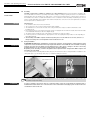
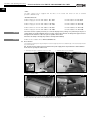
Four mounting brackets including rubber buffers (Fig.1) are mounted to the unit for ceiling installation. Installation to the
ceiling takes place e.g. with hanger bolts (Fig. 2) or suitable mounting accessories
fig.1
fig.2
Mounting bracket
When installing to ceiling, it is recommended that the heat exchanger is removed from the unit to reduce the
T IP P ! installation weight when lifting.
ATTENTION
In order to guarantee the proper outlet of condensate water, it must be ensured that the ventilation unit is
installed with a lateral incline of 3° in the direction of the condensation outlet (Fig. 4); refer to label next to the
condensation outlet on the unit.
5
Installation and operating instructions
Central ventilation units KWL EC 700/1400/2000 D Pro / WW
UK
2.2
Condensation outlet
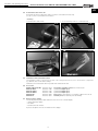
The humidity of exhaust air condenses to water during the heating period. A lot of condensate can build up in new buildings with large numbers of people. The condensate water collected in the condensate tub made of stainless steel is
discharged via a ball siphon (not included in scope of delivery). An incline of at least 3° (Fig.4) must be observed and
the connection to the local drainage system must be ensured on site.
fig.3
fig.4
Incline min 3°
Condensation
outlet drains,
Ø 22 mm
Condensation outlet
An open outlet should be connected (see design Fig. 4) due to odour development in dried-out siphons.
The drainage pipe route must not rise above the siphon!
The condensation outlet must be made frost-proof!
ATTENTION
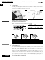
2.3
Flange connection / adapter pieces
KWL EC ... Pro / WW types are supplied with a flange connection as standard
fig.5
K
Unit type
Dim.
K
L
KWL EC 700 D ...
mm
224
324
KWL EC 1400 D ...
mm
274
524
KWL EC 2000 D ...
mm
324
624
L
Dim. in mm
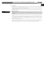
Adapter pieces for ducts and piping are available from Helios:
fig.6
fig.7
F
IH
HK
F
JF
F
IHJ
HHJ
F
LF
È GF
KH
Unit type
LH
J
J
Description
Order No.
Fig.6
KWL EC 700 D..
KWL-ÜS 700 D
4206
Pipe diameter in mm
250
Fig.7
KWL EC 1400 D..
KWL-ÜS 1400 D
4207
315
Fig.8
KWL EC 2000 D..
KWL-ÜS 2000 D
4208
400
The piping must be firmly and tightly connected to the connection valves. Refer to the illustrations for the
arrangement of ventilation ducting.
☞
2.4
IM
È GF
IH
J
ATTENTION
fig.8
K
LF
JF
È GF
NOTE
IG
HMJ
F
HK
Air ducting, Ventilation circuit
When designing the ductwork, use the shortest possible runs. Airtight connections and changeovers must be ensured
for the best possible heat recovery. To avoid pressure losses, dirt build-up and noise, use smooth ducts (plastic or rigid
ducting). For main lines (outside, exhaust air, supply air distributor, extract collector) DN (KWL EC 700 D = 250 mm;
KWL EC 1400 D = 315 mm; KWL EC 2000 D = 400 mm) or the corresponding duct is to be provided, and the ø is
reduced accordingly for branch lines.
Exhaust and outside air pipes are to be insulated in an appropriate way to reduce condensation. The minimum insulating thicknesses pursuant to DIN EN 1946-6, 05/2009 are to be observed. If supply and extract air ductwork runs
through unheated rooms, insulation must be provided to reduce heat losses. Fresh air should be supplied to living and
bedrooms and extraction should take place in bathrooms, toilets and kitchens. To balance the whole system, supply
and extract openings should be provided with adjustable valves (accessories).
A filter (accessory) is to be connected for the extraction of polluted extract air. The installation of extractor hoods to the
system is not permitted (reasons: dirt, fire danger, hygiene). Sufficient overflow openings (door gap, door grilles) are to
be provided to ensure air circulation within the room.
All fire and building regulations must be observed!
6
Installation and operating instructions
Central ventilation units KWL EC 700/1400/2000 D Pro / WW
UK
WARNING
2.5
Unit insulation
If installed in heated rooms and higher humidity, condensation can occur on the outside of the unit in the outside and
extract air area. In this case, water-vapour-tight insulation is to be installed on the surface in this area. Furthermore the
outside and exhaust air ductwork should be insulated sufficiently.
If installed in unheated areas (e.g. frost-protected attic), sufficient insulation must be installed on the outside of the unit.
Otherwise, condensate formation could occur on the casing sides. Frost-proof condensate drainage must be installed,
perhaps with a heater.
2.6
Electrical connection
All work must be carried out with the equipment fully isolated from the power supply. The electrical connections must be carried out in accordance with the relevant wiring diagram and must only be carried by certified
electricians!
The unit is equipped with a main switch and an isolator which can be secured against unauthorized switching with a
U-lock.
The relevant standards, safety regulations (e.g. DIN VDE 0100) and the technical connection conditions of the local
electricity supply companies must be observed. An all-pole mains switch / isolator, with a contact opening of at least 3
mm (VDE 0700 T1 7.12.2 / EN 60335-1) must be provided. The main switch and/or isolator can be secured against
unauthorized switching with a U-lock.
The surface-mounted controller with touchscreen is connected to the unit by means of a 5 m connecting cable (also
available in 10 or 20 m length). The electrical connection of the KWL EC ... D Pro / WW takes place directly in the terminal box. If special components are to be connected, the connections must be made in the terminal box.
7
Installation and operating instructions
Central ventilation units KWL EC 700/1400/2000 D Pro / WW
UK
CHAPTER 3
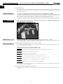
3.0
Unit overview
Hot water heater
(Type KWL EC ...D Pro WW)
Hot water connection
for WHSH... (Type KWL EC ...D Pro WW)
FUNCTIONAL
DESCRIPTION
Bypass (not visible)
Casing
Isolator
Terminal box
F5-Extract air filter
Condensation outlet
Ø 22mm
F7-Outside air
filter
EC-high performance
ventilator – supply air
Elec. pre-heater
(not visible)
EC-high performance
ventilator – Exhaust air
Cross counter flow heat exchanger
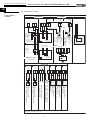
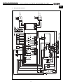
3.1
Condensation tub
Functional diagram
fig.9
When
using a heater,
the
pipe system
must be
with Gtemperature-resistant
nonX{ l{{z}
{{
^{{}{B
zwprovided
h
~{
z wy~ z{ or
^{{}{
flammable
piping 1m before and
the
heater (e.g h
~
spiral{{~{
duct)
{{wx{
z}{
xDafter
y~
x{xw{
{z{ >DXD my{|w
~?
Supply
p| air
H
[ I
Wx| air
Extract
[ H
_ G jww
_ H
I
[ G
H
H
jw{
Exhaust
\
|
air
G >J?
fw{
I
H
Outside
air
WÊ{|
Controller
with integrated
a
|
x{z{{{{
{}{{sensor
j{{w|~{
temperature
>hw{}{
_ww
?
(installation in room)
Fig:
Pro/WW
WxxDKWL
ambEC
[Y 700
MFFZDfhe
mm
Pos. f
DNameX{{}
Item No.
WDCdD
Ext. 1 Outside air sensor
.............
[ G
WÊ{||~{
CCCCC
Ext. 2[ Supply
air sensor
.............
H
p||~{
CCCCC
Int. 1 _ GExtract
air sensor
.............
Wx||~{
CCCCC
Int. 2 _ HExhaust
air sensor/frost-protection
sensor
.............
\
||~{
E \
y~|~{
mjWT
CCCCC
jww
\
y~|~{
>WW
x{ unit
mmC]{
{{?
CCCCC
Talarm
Frost-protection
sensor mmC^{{}{
WW heater (only for
types)
.............
jw{
\
y~|~{
> x{
CCCCC
Twater
Frost-protection
sensor mmC^{{}{
WW heater returnhyw|
(only for WW
unitmmC]{
{{?
types)
.............
I
aww|~{
>b{|{|w}
b|}}{
?
CCCCC
Ext. 3[ Duct
sensor
(ventilation
unit scope
of delivery)
.............
a
|
x{z{{{{ {}{{ j{{w|~{
Panelfw{
Controller
with integrated temperature
.............
D Wy~wx{
h`GH >b
}{sensor
K ? including connection cable RJ12 (lenght 5m)CCCCC
x{}w}y
FJHFL
1
Adapter
piece KWL-USambCi
700 D MFF Z
04206
G Adapter
x{}w}y
FJHFM
piece KWL-USambCi
1400 DGJFF Z
04207
x{}w}y
FJHFN
Adapter
piece KWL-USambCi
2000 DHFFF Z
04208
H Temperaturej{{wx{
z}{
xD y~ x{xw{
h
~ >DXD
CCCCC
2
resistant or non-flammable
piping (e.g. spiral
duct)my{|w
~?
.............
I
j{{wx{
z}{ xD y~ x{xw{ Z
}
CCCCC
3
Temperature- resistant or non-flammable insulation
.............
8
Installation and operating instructions
Central ventilation units KWL EC 700/1400/2000 D Pro / WW
UK
3.2 Functions
3.2.1 Internal pre-heater
According to criteria for passive houses, a pre-heater is mandatory to prevent the Cross counter flow heat exchanger
from freezing! The pre-heater is located behind the outside air filter F7.
– Detailed pre-heated regulation:
The pre-heater will be active if the following conditions are met:
Condition I: Outside air temperature (sensor EXT1) less than - 4 °C
Condition II: Exhaust air temperature (sensor INT2) less than + 0 °C
Condition III: Pre-heater is not deactivated in menu section (12 Pre-heater)
If all conditions are met, the pre-heater will be controlled corresponding to the difference to achieve a constant outgoing air temperature.
The pre-heater will be deactivated if the following conditions are met:
Condition I: Outside air temperature (sensor EXT1) is more than -3 °C
or
Condition II: Exhaust air temperature (sensor INT2) is more than +4 °C
IMPORTANT NOTE
☞
Important note:
The pre-heater only activates if the supply air ventilator is extracting the minimum flow rate and there are no errors. If
the KWL unit is switched to standby mode, the supply air ventilator will run for 60 seconds in case the pre-heater was
activated before that. If the pre-heater before this and, for example, the KWL unit is switched to standby 20 seconds
later, the supply air ventilator will then only run for 40 seconds.
NOTE
☞
General information on the pre-heater
The pre-heater is equipped with two safety temperature limiters, the STL (auto reset = trigger temp. +50 °C) and
(manual reset = trigger temp. +120 °C) are connected in series. Once a safety temperature limiter is triggered, the preheater will be disconnected from the power supply and an error will be displayed on the controller.
3.2.2 Heat exchanger frost-protection
The heat exchanger frost-protection function is divided into 3 steps:
Step I: Pre-heater activation (see section 3.1.1)
Step II: Reducing the flow rate / Exhaust and supply air ventilator
Condition I: Pre-heater has been switched on for longer than 3 minutes
Condition II: Exhaust air temperature (sensor INT2) is less than 0 °C
If both conditions are met, the exhaust and supply air ventilator will reduce by 50 %, however, not more than 50 % of
the total flow rate. The pre-heater will not be deactivated in this period.
Step III: Emergency shutdown Supply air ventilator
Condition I: The flow rate of the exhaust and supply air ventilator is reduced for longer than 5 minutes
or
Condition II: The pre-heater is deactivated.
AND
Condition III: Exhaust air temperature (sensor INT2) is less than 0 °C
If the conditions are met, the pre-heater will be deactivated and the supply air ventilator will be shut down.
The Heat exchanger frost-protection will be deactivated if the following conditions are met:
Condition I: Outside air temperature (sensor EXT1) is more than -3 °C
or
Condition II: Exhaust air temperature (sensor INT2) is more than +4 °C
If the conditions are met, the heat exchanger frost-protection will be deactivated.
9
Installation and operating instructions
Central ventilation units KWL EC 700/1400/2000 D Pro / WW
UK
3.2.3 Hot water heater
A hot water heater ensures the comfortable and energy-efficient post-heating of supply air. This is particularly useful if
the supply air (heated outside air from the heat exchanger) is to be heated to a higher temperature level (normally room
temperature or higher).
KWL EC .. Pro WW
ATTENTION
☞
– Connection and regulation of internal hot water post-heater (only Type KWL EC .. Pro WW)
The outside air and supply air which has been pre-heated by the heat exchanger can be additionally heated with the
internal hot water heater. A WHSH 1100 24V 0-10V Item No.: 8819 is required for this (WHSH not included in scope of
delivery), and the circulating pump integrated in the WHSH must be operated at medium capacity.
When using the hot water heater, it must be ensured that the hot water supply is guaranteed at all times, for example,
to prevent frost damage to the heater. The hydraulic unit must be connected to the ventilation unit by a specialist.
A cover flat must be mounted in the outside air and in the exhaust air on KWL EC .. PRO WW units to
prevent damage to the hot water heater!
fig.10
KWL EC .. Pro
☞
– Connection and regulation of external hot water post-heater (only Type KWL EC ... D PRO)
It is possible to integrate an external hot water post-heater on unit types KWL EC 700/1400/2000 D PRO. The heater
can be regulated with the controller by regulating the ventilation unit.
KWL EC .. Pro WW
☞
3.2.4 Frost-protection Hot water heater (only Type KWL EC . PRO WW)
The hot water heater frost-protection prevents hot water heater from freezing at extremely cold temperatures and in
case of non-functioning central heating.
Frost-protection is active if the following conditions are met:
Condition I: Outside air temp. (sensor EXT1) is less than +2 °C
Condition II: Temperature behind the heat exchanger (supply air) (sensor EXT2) is less than +5 °C
or
Condition III: Outside air temp. sensor (EXT1) is defective
or
Condition IV: Temperature sensor (EXT2) is defective
AND
Condition V: Hot water return flow temperature (sensor Twater) is less than +15 °C
or
Condition VI: Temperature behind the hot water heater (sensor Talarm) is less than +6 °C
or
Condition VII: Temperature sensor on hot water return flow (Twater) is defective
or
Condition VIII: Temperature sensor on hot water heater (Talarm) is defective
If both conditions are met, the frost-protection function will activate, and as soon one of the following conditions is met,
the frost-protection function will activate.
3.2.5 Frost-protection for downstream hot water heater
If the supply air temp. falls below +5 °C, the supply air ventilator will shut down. An error code will be displayed on the
controller.
10
Installation and operating instructions
Central ventilation units KWL EC 700/1400/2000 D Pro / WW
UK
3.2.6 Thermal comfort temperature
Condition I: Supply air temp. (sensor EXT3) is less than +16,5 °C
Condition II: Outside air temp. (sensor EXT1) is less than -10 °C
The pre-heater will be controlled corresponding to the difference to achieve a constant supply air temperature.
3.2.7 Cover flaps, 230V~ for outside and exhaust air (to be provided on site)
The cover flaps which are to be provided on site prevent cold draughts in case of faults or when the unit is switched off.
Faults include:
- Frost-protection of hot water heater
- Frost-protection of heat exchanger (step 3)
IMPORTANT NOTE
☞
A cover flap must be mounted in the outside and exhaust air for the KWL EC .. PRO WW (internal hot water
heater) to prevent frost damage to the heater or heat exchanger.
3.2.8 RUN output
The RUN output can, for example, serve as a signal for building control systems to determine the system status. A relay
output is located on the unit (label: “RUN“) and as soon as the KWL unit is in ventilation mode, the contact is closed.
3.2.9 External contact (signal)
The KWL unit can be put into standby mode or ventilation mode through the “External contact“ function.
– Contact open = Standby mode
– Contact closed = Ventilation mode
If the KWL unit is switched to ventilation mode via the controller > Service menu 10: “Ext. sensor“ (see also Page 20),
the external contact must first be closed and then opened to put the KWL into standby mode. This is also the case if
the KWL unit has been put into standby mode via the controller. The external contact must first be opened and then
closed to put the KWL into ventilation mode.
3.2.10 Fire mode (fire contact)
The KWL unit can be put into two operating modes (exhaust air mode or
standby mode) through the “Fire mode“ function (Fire contact):
– “Unit off“ (Standby)
– “Extract air“
These modes can be selected from the controller > Service menu 14: “Fire mode“ (see also Page 21). If the fire contact
is opened, the previously selected operating mode will be activated.
The controller will be locked during this time.
3.2.11 Condensate contact
Condensate contact is an error message "condensation tub overflow" on the controller. The ventilators will be shut
down. Function is not required!
3.2.12 Monozone “manual“
"Monozone" / "CAV" = Operate the ventilation unit in constant airflow mode.
This function can be selected on the controller > Service menu 1: “Ventilation mode“ (see also Page 18).
If it is necessary to operate the ventilation unit at a desired flow rate, the operating mode "Monozone“ / “CAV" is recommended. The desired flow rate is then set directly on the main menu by pressing the “Flow rate value“ on the display.
3.2.13 Monozone „auto“
The ventilation unit can also be operated in Automatic mode "Monozone“ / “CAV"-mode.
– Condition: Sensor must be activated (Service menu 10).
Automatic mode can be selected on the controller > Service menu 1: “Ventilation mode“ (see also Page 18).
Press "M" key. The unit will switch to Automatic mode which is indicated with an "A". Depending on the connected and
activated sensors, it is also possible to enter a “limit value (ppm)“ for the respective sensors. When the limit value is reached, the ventilation unit will operate at the max. power available.
The ventilation unit therefore increases or decreases the flow rate capacity before reaching the limit value depending on
the target/limit value comparison. Pressing the "A" symbol again switches the unit back to the “manual“ ventilation
mode ("M" symbol).
3.2.14 Multizone
"Multizone" / "VAV" = Operate the ventilation unit in the constant pressure mode
The mode can be selected on the controller > Service menu 1: “Ventilation mode“ (see also Page 18).
Enter "Multizone“ / “VAV"-mode by pressing "Monozone". The current “flow rate (m3/h)“ is shown on the display (cannot be changed), as well as the current set “constant pressure value (Pa)“. The desired constant pressure value can be
increased or decreased by pressing the +/-key. The minimum constant pressure value is limited to 20 Pa.
Some ventilation applications require the use of the ventilation unit in constant pressure mode (“Multizone“ /“VAV“mode). The "constant pressure" operating mode is typically selected if the ventilation unit is to ventilate different
zones/units (Multizone) with variable flow rate requirements.
EXAMPLE
☞
In an apartment building, six residential units are ventilated with a central ventilation unit. Each of the residential units
can vary the flow rate by controlling a valve. In this case, the technical planner will normally calculate a constant pressure for nominal flow rate for the ventilation ductwork. If a valve is then closed, the static pressure in the ventilation ductwork will change at a constant flow rate and cause a deviation from the calculated and set constant pressure. The
11
Installation and operating instructions
Central ventilation units KWL EC 700/1400/2000 D Pro / WW
UK
deviation will be detected by the control and the ventilation unit will begin to reduce the flow rate until the desired constant pressure is reinstated. The resulting flow rate will distribute to the respective residential units corresponding to the
ventilation ductwork planning.
Constant pressure means static pressure in the duct network. In case of changes in pressure in the duct network (e.g.
by opening and closing flaps), the set constant pressure (target value) is achieved by regulating the airflow rate (reduction or increase of the ventilator speed).
3.2.15 Automatic bypass
– What is the function of Automatic bypass in your ventilation unit?
The main function of Automatic bypass is not to channel the fresh outside air through the heat exchanger, but rather
through the so-called “bypass channel” in the unit past the heat exchanger and directly into the supply air rooms.
Terminology:
Bypass closed: Outside air is channelled through heat exchanger into the room = Active heat recovery
Bypass open:
Outside air is channelled through heat exchanger into the room = Active heat recovery
Outside air is channelled directly into the room = Inactive heat recovery, indirect “cooling“ of room air.
– When is the unit bypass used?
The bypass is normally used in the summer months for so-called “night cooling“. With regard to night cooling. the effect
of cool outside temperatures is used in comparison to room or inside temperatures.
The bypass can also be used in transition periods (spring and autumn) if the room temperature is significantly higher
than the outside air temperature during the day due to high windows (“natural bypass cooling“).
The night cooling effect and “natural bypass cooling“ is strongly influenced by the temperature differences between
outside air/supply air and room air, the flow rate, the shade and the required cooling loads. Bypass cooling will never
replace air conditioning!
–Bypass functional description
If the ventilation unit is supplied with system voltage, the bypass will close completely. The bypass will open if the all of
the following conditions are met:
Condition 1: The room temperature is higher than the set target supply air temp. (factory setting: 21 °C)
Condition 2: The outside air temperature is higher than the set outside air temperature limit (factory setting: 15 °C).
The temperature of the outside air temperature limit, can be changed on the controller > Service menu:
“Bypass settings“ (see also Page 20).
Condition 3: The room temperature is higher than the outside air temperature.
The bypass is closed if one of the aforementioned conditions is no longer met!
3.2.16 Demand-driven regulation of ventilation units through CO2- and humidity sensors
The ventilation unit has the connection option for a sensor (CO2 or humidity). The sensor is connected directly to the
unit motherboard pursuant to the wiring diagram.
The CO2 controller monitors the CO2-concentration in the room and ensures increased ventilation at higher concentrations to prevent, for example, signs of fatigue, the lack of concentration or headaches. The CO2 sensor is deactivated
on the service menu of the controller when delivered from the factory.
The humidity controller ensures increased ventilation at higher levels of indoor humidity (% r.F.) for the removal of moisture to counteract damage to the building material. The humidity controller is deactivated when delivered from the fac
tory.
In order to activate the sensor controller, the CO2-sensor or humidity sensor must be activated on the service menu >
“Ext. sensor“ (see also Page 20) of the controller after connection to the motherboard.
Furthermore, the ventilation unit must be operated in “Monozone“-mode and “Automatic-mode“ (settings on service
menu > “Ventilation mode“ (see also Page 18), to set the desired CO2 limit value (factory setting 1000 ppm) or desired
humidity limit value (factory setting 50 % r.F.).
NOTE
☞
The unit airflow rate is controlled automatically depending on the CO2 concentration or the relative humidity. The airflow
rate is automatically increased with the increase of the respective sensor value. If the set limit value is exceeded, the
ventilation unit will work at max. flow rate capacity.
3.2.17 Vent calibration
The maximum operating point of the ventilation unit is determined during ventilator calibration. in this respect, the ventilation unit runs at 100% ventilator capacity for a defined period of time. The maximum achievable flow rate and the
corresponding static pressure in the ductwork is shown as a result of the ventilator calibration.
The calibration can be activated on the controller > Service menu 2: “Vent calibration“ (see also Page 19).
The calibration takes around 3-5 minutes!
ATTENTION
In the context of starting up and adjustment of the ventilation unit, the ventilator calibration must be carried
out before adjusting the ventilation unit! All control dampers should be pre-set to the desired target value, all
valves should be completely opened.
12
Installation and operating instructions
Central ventilation units KWL EC 700/1400/2000 D Pro / WW
UK
Note:
13
Installation and operating instructions
Central ventilation units KWL EC 700/1400/2000 D Pro / WW
UK
4.0
CHAPTER 4
Surface-mounted controller with touch screen
The central ventilation unit is controlled with a surface-mounted controller (Fig. 11). It enables freely definable operating
levels within the total performance curve range, a weekly or daily programme as well as other features. The controller
comes with a control line (5 m) with a double sided RJ 12 plug for easy installation as standard.
CONTROLLER
fig.11
Direct software menu guide operation
through self-explanatory graphics via touchscreen.
Display indications:
➀ Menu
➁ Time
➂ Powersymbol / Stand-by
➃ Frost protection display WT / WW
➄ Temperature activated parameter (symbol)
➅ Target flow rate / Actual flow rate
➆ Actual sensor values
➇ Warning symbo l/ Error display
MENU
☞
4.1
➃
➄
➀
➁
➂
➅
➇
➆
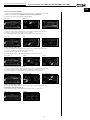
Operating menu / Parameter settings via touch screen
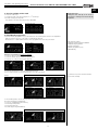
1. Starting up
Activate main isolator on the terminal box. Software parameters are imported.
2. Enter
➧
2. Operating mode – Display indicators
The control can be active in two operating modes “Ventilation mode“ and “Standby mode“.
The KWL unit always starts up in the operating mode that was last active before switching off.
Ventilation mode
Standby mode
3. Main menu
1. Press the “Menu“ key to enter the main menu
2. Press the “RETURN“ key to enter the initial menu
Main menu
➀
➁
➂
➄
➅
➆
Main menu – Symbol explanation:
➀ Weekly programme
➁ Language menu
➂ Target temperature
➃ RETURN key
➄ Brightness/contrast
➅ Service menu
➆ Airflow rate menu
➧
☛
➃
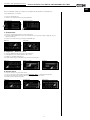
4. Select language
1. Press the “languages” key in the main menu
2. Select English, German or French in the language menu
3. Confirm by pressing the “RETURN“ key
Main menu
Language menu
☛
➧
☛
14
Installation and operating instructions
Central ventilation units KWL EC 700/1400/2000 D Pro / WW
UK
5. Set time and day of the week
Important note:
Setting the time and day of the week is
essential for creating a functional weekly
programme
1. Press the “Time“ key
2. Set time and day of the week using the or arrow keys
3. Confirm entry by pressing “OK“
OR: Return to the main menu by pressing “RETURN“
Time/day of the week
➧
☛
6. Daily/Weekly programme
Press the ”Weekly programme“ key on the main menu. The following main functions are adjustable:
- Daily menu: Daily sequence of the same 1-4 defined time intervals
- Weekly menu: 1-4 defined time intervals can be programmed for each day of the week
Weekly programme symbols:
➀ Activate weekly programme ON/OFF
➁ Daily/Weekly programme
➂ Target temperature
➃ Weekly programme query
➄ RETURN key
Weekly programme
☛
➧
➀
➁
➂
➃
➄
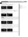
Example: Programming a weekly programme
1. Press the “On“ key. Weekly programme is active
2. Press the “Week“ key to activate the weekly menu
3. Press the “1– 4“key to enter the time intervals
☛
➧
☛
➧
☛
4. Press the “arrow keys“ to enter the desired time intervals.
Up to four time intervals can be programmed for each day of the week.
Example:
Time interval 1
☛
➧
☛
Time interval 2
☛
Time interval 3
☛
Time interval 4
☛
5. The following values can also be programmed for each time interval:
Flow rate and supply air temperature.
1. Press the “Temperature/Flow rate“ key
2. Enter target temperature
3. Enter target flow rate
4. Confirm by pressing RETURN key
Target temp. Supply air
☛
➧
Target flow rate
☛
☛
15
The “X Delete“ key resets all entered values
(for each time interval).
Installation and operating instructions
Central ventilation units KWL EC 700/1400/2000 D Pro / WW
UK
Once the individual settings are complete, the programmed switching times and parameters can be displayed in an overview.
1. Press the “Overview“ key
2. Return to the weekly menu by pressing “RETURN“
Daily/weekly menu
Overview time intervals
➧
☛
☛
Copy time intervals
1. Press the “Overview“ key
2. Press the “Copy“ key. The displayed day of the week is copied.
3. The copy can be transferred to the desired days of the week. Activate box!
4. Confirm entry by pressing “OK“
5. Return to the weekly menu by pressing “RETURN“
Weekly menu
Copy function
Transfer copy to week day
➧
☛
☛
➄
➧
☛
Example: Programming a daily programme
1. Press the “On“ key. Daily programme is active
2. Press the “Day“ key to activate the daily menu
3. Press the “1– 4“ key to enter the time intervals
☛
➧
☛
➧
☛
4. „ Pfeiltasten“ drücken, um die gewünschten Zeitintervalle einzugeben.
Es können bis zu vier Zeitintervalle für jeden Tag programmiert werden.
Example:
Time interval 1
☛
Time interval 2
The “X Delete“ key resets all entered values
(for each time interval).
➧
☛
Time interval 3
☛
Time interval 4
☛
5. The following values can also be programmed for each time interval: Flow rate and supply air temperature.
1. Press the “Temperature/Flow rate“ key
2. Enter target temperature
3. Enter target flow rate
4. Confirm by pressing RETURN key
Target temp. Supply air
☛
➧
Target flow rate
☛
☛
16
Installation and operating instructions
Central ventilation units KWL EC 700/1400/2000 D Pro / WW
UK
Once the individual settings are complete, the programmed switching times and parameters
can be displayed in an overview.
1. Press the “Overview“ key
2. Return to the weekly menu by pressing “RETURN“
Daily/weekly menu
Overview time intervals
➧
☛
☛
7. Temperatures
1. Press the “Target temperature“ key in the main menu.
2. Enter the target temperature for the selected channel sensor (factory setting = supply air sensor)
with the arrow keys
3. Return to the main menu by pressing the “RETURN“ key
Main menu
Termperature
☛➧
☛
8. Brightness – Contrast – Tone
1. Press the “Brightness/Contrast“ key in the main menu
2. Set brightness and contrast using the slide control
3. Activate or deactivate keypad tone
4. Confirm by pressing the “RETURN“ key and return to main menu
Main menu
Brightness/contrast
➧
☛
Keypad tone
☛
☛
9. Service menus
1. Press the “Service“ key in the main menu.
2. Access to the service menu with password: Password: 1616 > confirm by pressing “OK“
3. Select the desired service function with the arrow keys or the slide control
4. Confirm selection by pressing “OK“
Main menu
Password query
☛
➧
☛
Service menus
➧
☛
17
Installation and operating instructions
Central ventilation units KWL EC 700/1400/2000 D Pro / WW
UK
Service menu 1: Ventilation mode
1. Select the function “Ventilation mode“ in the service menu, confirm by pressing “OK“
2. Select the ventilation mode: Monozone / CAV or Multizone / VAV
3. Confirm by pressing the “RETURN“ key and return to the service menu
Service menu
Ventilation mode:
"Monozone" / "CAV"
= Operate the ventilation unit in the constant
airflow mode.
"Multizone" / "VAV"
= Operate the ventilation unit in the constant
pressure mode
Select ventilation mode
☛
➧
Ventilation mode: Monozone / CAV
= Operate the ventilation unit in the constant airflow mode
Manual:
If it is necessary to operate the ventilation unit with a defined flow rate, then the manual operating mode
"Monozone / CAV" is recommended. The desired flow rate is set on the main menu by pressing the flowrate value.
1. “Monozone“ = activated unit mode
2. Confirm by pressing the “RETURN“ key and return to the service menu
Ventilation mode Monozone
☛ ➧
manual
☛
➄
Automatic:
In case of connected and activated sensors in “Service menu 10“, the ventilation unit can also be opened in
Automatic mode "Monozone/CAV" mode. Press the "M" key. The unit changes to Automatic mode which is
indicated with an "A". Depending on the connected and activated sensors, it is also possible to enter a “limit
value (ppm)“ for the respective sensors. When the limit value is reached, the ventilation unit will operate at
the max. power available. The ventilation unit therefore increases or decreases the flow rate capacity before
reaching the limit value depending on the target/limit value comparison.
Pressing the "A" symbol again switches the unit back to the “manual“ ventilation mode ("M" symbol).
Ventilation mode Monozone
☛ ➧
Automatic
☛
Ventilation mode: Multizone / VAV
= Operate the ventilation unit in the constant pressure mode
Some ventilation applications require the use of the ventilation unit in constant pressure mode (“Multizone“
/“VAV“). The "constant pressure" operating mode is typically selected if the ventilation unit is to ventilate different zones/units (Multizone) with variable flow rate requirements.
1. Enter "Multizone“ / “VAV" mode by pressing the "Monozone" key.
2. The current “Flow rate value (m3/h)“ is shown on the display (cannot be changed) as well as the current
set “Constant pressure (Pa)“. The desired constant pressure value can be increased or decreased by pressing the +/- key. The minimum constant pressure value is limited to 20 Pa.
Ventilation mode Multizone
Set constant pressure
☛ ➧
☛
Note: Constant pressure means static pressure in the duct network. In case of changes in pressure in the
duct network (e.g. by opening and closing flaps), the set constant pressure (target value) is achieved by
regulating the airflow rate (reduction or increase of the ventilator speed).
18
Installation and operating instructions
Central ventilation units KWL EC 700/1400/2000 D Pro / WW
UK
Service menu 2: Vent calibration
1. Select the “Vent calibration“ function in the service menu, confirm by pressing “OK“
2. Press the “Calibration“ key. Calibration takes around 3-5 minutes!
3. Return to the service menu by pressing “RETURN“
Service menu
☛
Calibration
☛
➧
➧
Service menu 3: PIN control
1. Select the “PIN control“ function in the service menu, confirm by pressing “OK“
2. Press the “key“ key on the control to lock or activate
3. Confirm by pressing the “RETURN“ key and return to the service menu
Service menu
☛
PIN
➧
☛
➧
Service menu 4: Start mode
1. Select the “Start mode“ function in the service menu, confirm by pressing “OK“
2. Press the “ventilator“ key and set the desired flow rate
3. Set the minutes (2-60) with the arrow keys
4. Confirm by pressing the “RETURN“ key and return to the service menu
Service menu
☛
Settings
➧
Settings
☛
➧
☛
Service menu 5: Channel temperature
1. Select the “Channel temp.“ function in the service menu, confirm by pressing “OK“
2. Increase or reduce the max./min. channel temperatures with the arrow keys
3. Confirm by pressing the “RETURN“ key and return to the service menu
Service menu
☛
Max. channel temp.
➧
Max.
☛
Min. channel temp.
☛
➧
Min.
Service menu 6: PID settings
1. Select the “PID settings“ function in the service menu, confirm by pressing “OK“
2. PID values must not be altered!
3. Confirm by pressing the “RETURN“ key and return to the service menu
Service menu
☛
PID values
➧
19
Installation and operating instructions
Central ventilation units KWL EC 700/1400/2000 D Pro / WW
UK
Service menu 7: Temperature sensor
1. Select the “Temperature sensor“ function in the service menu, confirm by pressing “OK“
2. Select “Control“ key
3. Select “Supply air“ key, supply air sensor is activated
4. Select “Extract air“ key, extract air sensor is activated
5. Confirm by pressing the “RETURN“ key and return to the service menu
Service menu
PID values
Servicemenü
Kalibrierung
☛
➧
☛ ➧
Service menu 8: Offset ventilators
1. Select the “Offset Vent.“ function in the service menu, confirm by pressing “OK“
2. Supply air: Press arrow keys and increase or decrease speed
3. Extract air: Press arrow keys and increase or decrease speed
4. Confirm by pressing the “RETURN“ key and return to the service menu
Supply air speed setting
Service menu
☛
☛
Extract air speed setting
☛➧
➧
☛
Service menu 9: Function test
Various control parameters (sensors, ventilators etc.) can be tested in real-time in this menu.
The function test must be carried out by a specialist, so that the controls and/or the unit is not
damaged!
1. Select the “Function test“ function in the service menu, confirm by pressing “OK“
2. Press the “+“ or “-“ key or “Flap/Run“ key to set the desired parameter
(refer to symbol explanation on right)
3. Press on “Display field“ to return to the service menu
Service menu
Function test display
Function test
Function test – Symbol explanation:
10
☛
➧
➧
☛
➧
Service menu 10: External sensor
1. Select the “External sensor“ function in the service menu, confirm by pressing “OK“. The following external sensors can be activated: CO2 sensor (CO2), humidity sensor (RH) and mixed gas (VOC)
2. Select the desired external sensor
3. Confirm by pressing the “RETURN“ key and return to the service menu
Service menu
☛
External sensor
☛
➧
Service menu 11: Bypass settings
1. Select the “Bypass settings“ function in the service menu, confirm by pressing “OK“
2. Increase or decrease the outside air limit temperature with the arrow keys
3. Confirm by pressing the “RETURN“ key and return to the service menu
Service menu
☛
Outside air limit
➧
7
6
9 13
11
12
8 14
1
2
3
4
5
1. Supply air ventilator
2. Extract air ventilator
3. Pre-heating
4. Post-heating
5. Bypass
– Temperature sensor
6. Extract air > Int. 1
7. Outside air > Ext. 1
8. Exhaust air temp. > Int. 2: -4 °C
9. Supply air temp. in the air supply duct > Ext. 3:
+29 °C
10. Supply air temp. in the ventilation unit > Ext. 2
13. Flow rate Supply air ventilator
14. Flow rate Exhaust air ventilator
– Accessories
11. Relay test cover flap
(1=open / 0=closed)
12. Relay test device 1=ON / 0=OFF
Note: Values in Pos. 6 to 10 cannot be changed!
☛
20
Installation and operating instructions
Central ventilation units KWL EC 700/1400/2000 D Pro / WW
UK
Service menu 12: Pre-heating
1. Select the “Pre-heating“ function in the service menu, confirm by pressing “OK“
2. Select “On“ (Factory setting) or “Off“ key to activate/deactivate pre-heating
3. Return to the service menu by pressing “RETURN“
Service menu
Pre-heater
➧
☛
☛
Service menu 13: External post-heating
1. Select the “External post-heating” function in the service menu, confirm by pressing “OK“
2. Press the “Without“ key if no post-heater is installed
3. Press the “Electrical “key if an electrical post-heater is installed
4. Press the “Water“ key if a hot water post-heater is installed
5. Confirm by pressing the “RETURN“ key and return to the service menu
Service menu
Ext. post-heater
➧
☛
➧
☛
Service menu 14: Fire mode
1. Select the “Fire mode“ function in the service menu, confirm by pressing “OK“
2. Select the “Unit off“ key, the unit switches off in case of fire
3. Select the “Extract air“ key, the extract Ventilator will operate at the max. ventilation level in case of fire
4. Confirm by pressing the “RETURN“ key and return to the service menu
Service menu
Fire ventilation
Fire alarm indicator on display
➧
☛
☛
Service menu 15: Factory setting (Reset)
All parameters set on the display can be reset.
1. Select the “Factory setting“ function in the service menu, confirm by pressing “OK“
2. Press the “Factory“ key. ATTENTION: All parameters will be deleted!
3. Return to the service menu by pressing “RETURN“
Service menu
Reset factory settings
➧
☛
Reset
☛
10. Flow rate menu
1. Select the “Flow rate“ key in the main menu
2. Increase or decrease the desired flow rate with the arrow keys
3. Confirm by pressing the “RETURN“ key and return to the service menu
Main menu
Flow rate
☛
➧
☛
21
Installation and operating instructions
Central ventilation units KWL EC 700/1400/2000 D Pro / WW
UK
10. Additional service function
1. Press the “Service“ key in the main menu
2. Access the additional service menu with password:
Password: 1717 > confirm by pressing “OK“
3. Overview (see description on right)
4. Confirm by pressing the “RETURN“ and return to the main menu
Additional service function –
Symbol explanation
6
KWL EC ...Pro unit display
Servicemenü
3
4
9
1
Vorheizung
☛
➧
☛
➧
KWL EC ...WW unit display
☛
➧
☛
Note:
8
5
☛
7
2
10
11
1.
2.
3.
4.
5.
6.
7.
8.
9.
10.
Flow rate Supply air ventilator
Flow rate Extract air ventilator
Supply air –outside air temperature (Ext. 1)
Pressure loss Filter F7- Supply air supply
Exhaust air sensor (WT frost protection), (Int. 2)
Extract air temp. of extracted air (Int. 1)
Pressure loss Filter (F5)- Extract air supply
Supply air temp. in the ventilation unit (Ext. 2)
Room temperature (Temp. control)
Pressure in the supply air duct
(behind the ventilation unit)
11. Supply air temp. in the supply air duct (Ext. 3)
Note:
The following applies to hot water devices or upon the
activation of an ext. hot water post-heater:
Wa => Frost protection sensor WW heater (Talarm)
Wr => Frost protection sensor WW heater return (Twater)
22
Installation and operating instructions
Central ventilation units KWL EC 700/1400/2000 D Pro / WW
UK
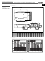
5.0
Dimensions
fig.12
KWL EC 700/1400/2000 D Pro
DIMENSIONS
CHARACTERISTIC CURVES
W
Front
Extract
Wx| air
X
b
Y
Outside
air
WÊ{|
Exhaust
\
|air
Supply
p|air
View from below
Wy~ò
ò{
Reverse side
c
d
ÈòHH
^
_
`
]
\
[
CHAPTER 5
a
JK
Z
Dim. in mm
C
D
E
F
G
H
I
J
K
L
M
øN
957
336
359
175
213
398
230
224
324
872
900
10
KWL EC 1400 D 1718 1280 1397
424
399
195
295
610
375
274
524
1312 1200
10
KWL EC 2000 D 2018 1600 1717
523
489
240
345
770
485
324
624
1632 2x700
10
Dim. in mm
KWL EC 700 D
5.1
A
B
1418 840
Adjustment
Adjustment of flow rate characteristic curves by type with details on recommended ventilation range:
∆pfa
Pa
KWL EC 700 D Pro / WW
Recommended:
Basic ventilation range
Nominal ventilation range
Intensiv ventilation range
V· m3/h
23
∆pfa
Pa
KWL EC 1400 D Pro / WW
Recommended:
Basic ventilation range
Nominal ventilation range
Intensiv ventilation range
V· m3/h
Installation and operating instructions
Central ventilation units KWL EC 700/1400/2000 D Pro / WW
UK
∆pfa
Pa
KWL EC 2000 D Pro / WW
Recommended:
Basic ventilation range
Nominal ventilation range
Intensiv ventilation range
V· m3/h
NOTE
☞
5.2. Minimum requirements for starting up
The start-up is carried out through a system calibration. “Vent-calibration“ (see also Page 20) is activated on the
controller > Service menu 2: and the system starts the system characteristic curve.
The calibration takes around 3-5 minutes!
In case of unusual system pressures, the installation must be checked! Foreign bodies or incorrect installation
can be potentially responsible for this.
6.0
CHAPTER 6
Service and maintenance
The unit must be must be disconnected from the power supply before any maintenance and installation
work or before opening the switch room! Danger of electric shock, moving parts (fan) and hot surfaces.
SERVICE AND
MAINTENANCE
WARNING
WARNING
6.1
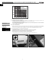
Removing/cleaning cross counter flow heat exchanger
DANGER OF INJURY! From falling or down-folding covers/inspection openings!
Maintenance and service work should always be carried out by two persons!
Heat exchanger are very heavy and can contain condensation water!
1. Undo screws (1) on unit cover, support cover in doing so and remove downwards (Fig. 13)
2. Loosen the fastening screw on the condensation tub (Fig. 14)
fig.13
(1)
24
fig.14
Installation and operating instructions
Central ventilation units KWL EC 700/1400/2000 D Pro / WW
UK
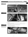
ATTENTION
☞
3. Fold condensation tub downwards (Fig. 15)
Tub may contain condensation water!
4. Pull the frost protection sensor WT from the heat exchanger fins (Fig. 16)
fig.15
WARNING
fig.16
Support heat exchanger in doing so!
5. Loosen all screws from the heat exchanger fastener (Fig.17)
6. Carefully pull cross counter flow heat exchanger from the unit (Fig.18)
fig.17
fig.18
Vacuum the fins with a vacuum cleaner to clean.
Do not clean the cross counter flow heat exchanger with water!
6.2
WARNING
IMPORTANT
☞
Filter change
The inspection openings on the ventilation unit enable the easy change of external filter (F7) and exhaust air filter (F5)
(see also section 2.8 Unit components)
Open the turn-lock fasteners on the inspection openings and fold the doors downwards to change the filter.
RISK OF INJURY! From down-folding covers /inspection openings!
1. Pull both filter locks downwards (Fig.19)
2. Carefully pull out and remove filter (Fig.20)
The filter’s direction of air flow must be taken into account!
fig.19
25
fig.22
Installation and operating instructions
Central ventilation units KWL EC 700/1400/2000 D Pro / WW
UK
– Filter
The KWL compact unit is equipped with fine filters on the outside and extract air side as standard
(pursuant to DIN EN 13779):
• Outside/exhaust air:
Air filter F5 Extract air 1St. ELF-KWL 700 D/5 No. 4189
Air filter F7 Supply air 1St. ELF-KWL 700 D/7 No. 4191
ELF-KWL 700 D/5 VDI No. 4190
ELF-KWL 700 D/7 VDI No. 4192
Air filter F5 Extract air 1St. ELF-KWL 1400 D/5 No.4193
Air filter F7 Supply air 1St. ELF-KWL 1400 D/7 No. 4195
ELF-KWL 1400 D/5 VDI No. 4194
ELF-KWL 1400 D/7 VDI No. 4196
Air filter F5 Extract air 1St. ELF-KWL 2000 D/5 No.4197
Air filter F7 Supply air 1St. ELF-KWL 2000 D/7 No. 4204
ELF-KWL 2000 D/5 VDI No. 4198
ELF-KWL 2000 D/7 VDI No. 4205
NOTE
☞
The filters must be regularly checked (see controller display factory setting every 6 months) for degree of
soiling (danger of mould formation) and, if necessary, cleaned. They must be exchanged for hygiene reasons
through one-off extraction or after one year of operation at the latest.
If the filters are damp or mouldy, they must be exchanged immediately!
WWW
☞
Air filters are also available online at www.ersatzluftfilter.de
6.3
Reset function
The manual reset takes place by pressing the reset lever (Fig.24), which is located directly on the electrical pre-heater.
Proceed as follows:
The unit must be must be disconnected from the power supply before any maintenance and installation
work or before opening the switch room!
1. Turn lid (1) and open “outside air” inspection flap
2. Pull both filter locks downwards
fig.23
fig.24
(1)
3. Remove outside air filter
4. Press down reset lever
fig.25
5. Subsequently re-insert outside air filter. Pay attention to air direction arrows!
6. Close inspection flap and reconnect ventilation unit to power supply.
26
fig.26
Installation and operating instructions
Central ventilation units KWL EC 700/1400/2000 D Pro / WW
UK
6.4
Condensation outlet in the unit
Ensure that the lateral condensation outlet (ø 22 mm) is secured above the base tray
(see also section 2.2) for maintenance measures.
– Cleaning
1. Condensation outlet nozzles
2. Loosen fastening screws on condensation tub
fig.27
3. Fold condensation tub downwards
fig.28
4. Clean with a cloth
fig.29
fig.30
6.5
Terminal box with isolator/main switch
The terminal box that is connected to the side of the casing ensures free access to the electronic components
(e.g. batteries, fuses or DIP switch settings.
Furthermore, the isolator/main switch is operable from underneath the unit.
6.6
Accessories
WHSH 1100 24V (0-10V)
KWL-ÜS 700 D
KWL-ÜS 1400 D
KWL-ÜS 2000 D
KWL-EC CO2
KWL-EC FF
6.7
Order No. 8819
Order No. 4206
Order No. 4207
Order No. 4208
Order No. 9958
Order No. 9953
Temperature regulation system for hot water heater
Symmetrical adapter piece
Symmetrical adapter piece
Symmetrical adapter piece
CO2 sensor for detecting the concentration of CO2 in the room air
Humidity sensor for detecting room air humidity
Error messages / Alarms
The following warning and/or alarm indicators are shown on the controller display:
– “Safety temperature limiter“
– “Fire alarm“
– “Condensation tub overflow“
A precise description of the error is indicated on the display!
27
85233 002 SS-1006 13.02.13
28
KWL EC-FF
Art.Nr. 9989
3 x 1,5mm²,
~
-
1
10
2
~~
+
11
12
Beispiel
Example
Helios-WHSH Type 24V/0-10V (SS-956)
With
WW-heater
Mit WW
Heizung
without
ohne WW-Type,
WW-Type,
WW-Register
WW-heater
extern,
extern,
Mischer
extern
Mixer external
24V/0-10V
24V/0-10V
0,2A
0-10V
9
10
~ ~ 24V~
46
9
GND2
11
12
9
10
GND
0-10V
WW-Type
45
Optional:
Optional:
on-side
Bauseitiger
isolator
/
Trennschalter
/
24V~
3
external Signal,
signal,
Externes
Potential-freeKontakt
contact!!
potentialfreier
N
GND2
3
M
24V~/
0-10V=
On/off switch
VDE 0700 T1 7.12.2
3 5
24V~/ 0-10V=
U
Circuit
board
Platine
11
M
1~
GND
0-10V
Klemmleiste
Terminal block
44
8
43
KWL EC-CO2
Art.Nr. 9988
Heater bei
for
Heizung
WW-Type,
WW-Type,
WW-Register
WW-heater
intern,
internal,
Mischer
extern
Mixer external
24V/0-10V
24V/0-10V
Betriebsvorschrift
Condensation
float switch,
Kondensat
Schwimmerschalter,
external
signal,
externes Signal,
Potential-freeKontakt
contact!!
potentialfreier
250V~
2A /AC1
24V~
GND2
CO2
GND1
15V~
N
PE
L1
2
42
RJ
41
RJ
Fire alarm,
Feueralarm,
external Signal,
signal,
externes
Potential-free
contact!
potentialfreier Kontakt !
7
GND2
CO2
15V~
GND1
15-24V~
/ 24V=
38 230V~
Supply
line 230V~
Zuleitung,
36
35
6
15-24V~
/ 24V=
External
heater,
Water pump
Externe
Heizung,
Wasserpumpe,
(Pro
and
WW)
max.
230V~/2A
(Pro und WW) max. 230V~/2A
N
33 230V~
34 230V~
L1 N PE
SignalVentilator
Ventilatoran,
on,
Signal
(Potential-free
contact)
(potentialfreier Kontakt) ! !
open/auf
5
Exhaust
air – cover flap,230V~
230V~
Fortluft
- Verschlussklappe,
external
components
externe Komponente
N
31 230V~
32 230V~
Signal system
der SicherheitsSafety
signal,
siehe
einrichtung,and
see installation
MBV-Montage
und
operating
instructions!
A1
GND
A2
GND
open/auf
Optional:
Optional:
To
be establisBauseits
bei
hed
on-side for
Raumluftheat
systems
abhängigen
that
depend
Feuerstätten
on
air. !
zu room
erstellen
A1
GND
Outside
air – cover flap,230V~
230V~
Außenluft
- Verschlussklappe,
external
components
externe Komponente
1
~
+
WIRING DIAGRAM
OVERVIEW
7.0
~
-
CHAPTER 7
~
+
Installation and operating instructions
Central ventilation units KWL EC 700/1400/2000 D Pro / WW
UK
Wiring diagram SS-1006
KWL EC 700 D Pro (WW), KWL EC 800 S Pro (WW)
fig.31
CircuitPlatine
board
24V~
4
RJ12
UX1
oder
or
6
M
24V~/
0-10V=
max. 50m
RJ12
Controller
Bedienelement
85234 002 SS-1007 13.02.13
29
1
5 x 1,5mm²
9
10
2
~~
+
46
11
12
Example
Beispiel
Helios-WHSH Type 24V/0-10V (SS-956)
With
WW-heater
Mit WW
Heizung
ohne WW-Type,
WW-Type,
without
WW-Register
WW-heater
extern,
extern,
Mischer
extern
Mixer external
24V/0-10V
24V/0-10V
0,2A
0-10V
~ ~ 24V~
45
KWL EC-FF
Art.Nr. 9989
9
10
11
12
9
10
GND
0-10V
WW-Type
GND2
3
44
Optional:
Optional:
on-side
Bauseitiger
isolator
/
Trennschalter
/
24V~
Heater bei
for
Heizung
WW-Type,
WW-Type,
WW-Register
WW-heater
intern,
internal,
Mischer
extern
Mixer external
24V/0-10V
24V/0-10V
KWL EC-CO2
Art.Nr. 9988
43
42
8
GND2
3
M
24V~/
0-10V=
3 5
24V~/ 0-10V=
U
Platine
Circuit
board
11
M
1~
GND
0-10V
Klemmleiste
Terminal block
external Signal,
signal,
Externes
Potential-free
contact!
potentialfreier Kontakt !
N
24V~
GND2
CO2
GND1
15V~
L1
L2
L3
N
PE
2
Condensation
float switch,
Kondensat
Schwimmerschalter,
external Signal,
signal,
externes
Potential-freeKontakt
contact!!
potentialfreier
250V~
2A /AC1
41
RJ
Fire alarm,
Feueralarm,
external Signal,
signal,
externes
Potential-freeKontakt
contact!!
potentialfreier
7
GND2
CO2
15V~
GND1
RJ
38 230V~
Supply
line 400 V~
Zuleitung,
36
35
6
15-24V~
/ 24V=
External
heater,
Water pump
Externe
Heizung,
Wasserpumpe,
(Pro
and WW)
WW)max.
max.230V~/2A
230V~/2A
(Pro und
N
33 230V~
34 230V~
L1 L2 L3 N PE
SignalVentilator
Ventilatoran,
on,
Signal
(Potential-freeKontakt)
contact)! !
(potentialfreier
open/auf
31 230V~
32 230V~
N
Exhaust
air – cover flap,230V~
230V~
Fortluft
- Verschlussklappe,
external
components
externe Komponente
open/auf
On/off switch
VDE 0700
T1 7.12.2
~
-
5
15-24V~
/ 24V=
A1
GND
Signal
SicherheitsSafetyder
system
signal,
see einrichtung,
installation siehe
and
MBV-Montage
und
operating
instructions!
Betriebsvorschrift
A1
GND
A2
GND
Outside
air – cover flap,230V~
230V~
Außenluft
- Verschlussklappe,
external
components
externe Komponente
1
~
+
Optional:
Optional:
To
be establisBauseits
bei
hed
on-side for
Raumluftheat
systems
abhängigen
that
depend
Feuerstätten
on
air. !
zu room
erstellen
~
-
7.1
~
+
Installation and operating instructions
Central ventilation units KWL EC 700/1400/2000 D Pro / WW
UK
Wiring diagram SS-1007
KWL EC 1400 D Pro (WW), KWL EC 1800 S Pro (WW)
fig.31
fig.32
Platine
Circuit
board
24V~
4
RJ12
UX1
oder
or
6
M
24V~/
0-10V=
max. 50m
RJ12
Controller
Bedienelement
KWL EC-FF
Art.Nr. 9989
5 x 2,5mm²
85235 002 SS-1008 13.02.13
30
1
10
2
~~
+
11
12
Example
Beispiel
Helios-WHSH Type 24V/0-10V (SS-956)
With
WW-heater
Mit WW
Heizung
without
WW-Type,
ohne WW-Type,
WW-heater
WW-Register
extern,
extern,
Mischer
extern
Mixer external
24V/0-10V
24V/0-10V
0,2A
0-10V
9
10
~ ~ 24V~
46
9
GND2
11
12
9
10
GND
0-10V
WW-Type
45
Optional:
Optional:
on-side
Bauseitiger
isolator
/
Trennschalter
/
24V~
3
external Signal,
signal,
Externes
Potential-freeKontakt
contact!!
potentialfreier
N
GND2
3
M
24V~/
0-10V=
3 5
24V~/ 0-10V=
U
Platine
Circuit
board
11
M
1~
GND
0-10V
Klemmleiste
Terminal
block
44
8
43
KWL EC-CO2
Art.Nr. 9988
Heaterbei
for
Heizung
WW-Type,
WW-Type,
WW-heater
WW-Register
intern,
internal,
Mischer
extern
Mixer external
24V/0-10V
24V/0-10V
Betriebsvorschrift
Condensation
float switch,
Kondensat
Schwimmerschalter,
external Signal,
signal,
externes
potentialfreier
Potential-freeKontakt
contact!!
250V~
2A /AC1
24V~
GND2
CO2
GND1
15V~
L1
L2
L3
N
PE
2
42
RJ
41
RJ
Feueralarm,
Fire alarm,
externes
external Signal,
signal,
potentialfreier
Potential-freeKontakt
contact!!
7
GND2
CO2
15V~
GND1
15-24V~
/ 24V=
38 230V~
15-24V~
/ 24V=
External
heater,
Water pump
Externe
Heizung,
Wasserpumpe,
(Pro und
and WW)
WW)max.
max.230V~/2A
230V~/2A
Supply
line 400 V~
Zuleitung,
36
6
35
L1 L2 L3 N PE
SignalVentilator
Ventilatoran,
on,
Signal
(Potential-freeKontakt)
contact)! !
(potentialfreier
33 230V~
34 230V~
N
open/auf
5
Exhaust
air – cover flap,230V~
230V~
Fortluft
- Verschlussklappe,
externe Komponente
external
components
N
31 230V~
32 230V~
On/off switch
VDE 0700
T1 7.12.2
~
-
open/auf
zu erstellen !
A1
GND
Safety
system
signal,
Signal der
Sicherheitseinrichtung, siehe
see installation
and
MBV-Montage
und
operating
instructions!
A1
GND
A2
GND
Außenluft
- Verschlussklappe,
Outside
air – cover flap,230V~
230V~
externe Komponente
external
components
1
~
+
Optional:
Optional:
To
be establisBauseits
bei
hed
on-side for
Raumluftheat
systems
abhängigen
that depend
Feuerstätten
on room air.
~
-
7.2
~
+
Installation and operating instructions
Central ventilation units KWL EC 700/1400/2000 D Pro / WW
UK
Wiring diagram SS-1008
KWL EC 2000 D Pro (WW), KWL EC 2600 S Pro (WW)
fig.33
Platine
Circuit
board
24V~
4
RJ12
UX1
or
oder
6
M
24V~/
0-10V=
max. 50m
RJ12
Controller
Bedienelement
31
yellow
black
brown
blue
black
brown
Unlined
Unlined
Outside air
flap
Exhaust air
flap
Siganl fan on
potentia-free
contact
Alarm
Heating
Heater for WW Type,
WW-heater internal,
Mixer external
0-10V
With WW-heater without
WW-Type, WW-heater
extern, Mixer external
24V/0-10V
Outside air sensor
Pre-heater
External
fire alarm
Heat exchanger
sensor
External
alarm condensate
External
siganl
Supply air sensor
Extract air sensor
Sensor input
Exhaust air sensor
Sensor
Hot water
Sensor
Water alarm
withe
blue
yellow
blue
yellow
withe
Exhaust air
motor
Supply air
motor
7.3
fig.34
Wiring plan KWL EC 700 D ...
UK
Central ventilation units KWL EC 700/1400/2000 D Pro / WW
Installation and operating instructions
32
yellow
black
brown
Exhaust air motor
Supply air motor
Outside air
flap
Exhaust air
flap
Siganl fan on
potentia-free
contact
Alarm
Heating
Heater for WW Type,
WW-heater internal,
Mixer external
0-10V
With WW-heater without
WW-Type, WW-heater
extern, Mixer external
24V/0-10V
Outside air sensor
Pre-heater
External
fire alarm
Heat exchanger
sensor
External
alarm condensate Supply air sensor
External
siganl
Extract air sensor
Sensor input
Exhaust air sensor
Sensor
Hot water
Sensor
Water alarm
withe
withe
blue
yellow
yellow
blue
withe
withe
Exhaust air
motor
Supply air
motor
7.4
fig.35
Wiring plan KWL EC 1400 D ...
UK
Installation and operating instructions
Central ventilation units KWL EC 700/1400/2000 D Pro / WW
33
yellow
black
brown
Exhaust air motor
Supply air motor
Outside air
flap
Exhaust air
flap
Siganl fan on
potentia-free
contact
Alarm
Heating
Heater for WW Type,
WW-heater internal,
Mixer external
0-10V
With WW-heater without
WW-Type, WW-heater
extern, Mixer external
24V/0-10V
Outside air sensor
Pre-heater
External
Heat exchanger
fire alarm
sensor
External
alarm condensate Supply air sensor
External
siganl
Extract air sensor
Sensor input
Exhaust air sensor
Sensor
Hot water
Sensor
Water alarm
withe
withe
blue
yellow
yellow
blue
withe
withe
Exhaust air
motor
Supply air
motor
7.5
fig.36
Wiring plan KWL EC 2000 D ...
UK
Installation and operating instructions
Central ventilation units KWL EC 700/1400/2000 D Pro / WW
All pictures without guarantee!
Please keep this manual for reference with the unit!
Print-No.:
82 600/03.13
www.heliosventilatoren.de
Service und Information
D HELIOS Ventilatoren GmbH + Co KG · Lupfenstraße 8 · 78056 VS-Schwenningen
CH HELIOS Ventilatoren AG · Steinackerstraße 36 · 8902 Urdorf
A HELIOS Ventilatoren · Postfach 854 · Siemensstraße 15 · 6023 Innsbruck
F
HELIOS Ventilateurs · Le Carré des Aviateurs · 157 avenue Charles Floquet · 93155 Le Blanc Mesnil Cedex
GB HELIOS Ventilation Systems Ltd. · 5 Crown Gate · Wyncolls Road · Severalls Industrial Park ·
Colchester · Essex · CO4 9HZ