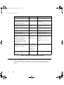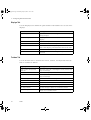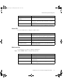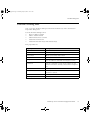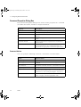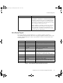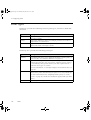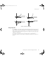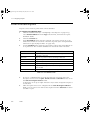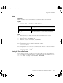
1
plscpcg.book Page i Monday, May 28, 2001 10:11 AM
PlantScape
Server and Client Configuration Guide
plscpcg.book Page ii Monday, May 28, 2001 10:11 AM
Document
Release
Issue
Date
TC-DSXX21
Release 400
0
June 2001
Notice
This document contains Honeywell proprietary information. Information contained herein is to
be used solely for the purpose submitted, and no part of this document or its contents shall be
reproduced, published, or disclosed to a third party without the express permission of
Honeywell Limited Australia.
While this information is presented in good faith and believed to be accurate, Honeywell
disclaims the implied warranties of merchantability and fitness for a purpose and makes no
express warranties except as may be stated in its written agreement with and for its customer.
In no event is Honeywell liable to anyone for any direct, special, or consequential damages.
The information and specifications in this document are subject to change without notice.
Copyright 2001 – Honeywell Limited Australia
Honeywell Trademarks
PlantScape®, SafeBrowse®, TotalPlant® and TDC 3000® are U.S. registered trademarks of
Honeywell, Inc.
Other Trademarks
Microsoft, and SQL Server are either registered trademarks or trademarks of Microsoft
Corporation in the United States and/or other countries.
Trademarks that appear in this document are used only to the benefit of the trademark owner,
with no intention of trademark infringement.
Support and Other Contacts
United States and Canada
ii
Contact:
Honeywell IAC Solution Support Center
Phone:
1-800 822-7673. In Arizona: (602) 313-5558
Calls are answered by dispatcher between 7:00 am and 5:00 pm
Mountain Standard Time. Emergency calls outside normal working hours
are received by an answering service and returned within one hour.
Facsimile:
(602) 313-5476
Mail:
Honeywell IAC TAC, MS1S1
16404 N. Black Canyon Highway
Phoenix, AZ 85023
plscpcg.book Page iii Monday, May 28, 2001 10:11 AM
Europe
Contact:
Honeywell PACE TAC
Phone:
+32-2-728-2657
Facsimile:
+32-2-728-2278
Mail:
Honeywell PACE TAC
Avenue du Bourget, 1
B-1140 Brussels, Belgium
Australia, New Zealand, and Fiji
Contact:
Honeywell Global TAC Pacific
Phone:
1300-36-4822 (within Australia)
+61-2-9353-7255 (outside Australia)
Facsimile:
+61-2-9353-8804
Mail:
Honeywell Global TAC Pacific
5 Thomas Holt Drive
North Ryde, NSW, 2113, Australia
Email
[email protected]
Elsewhere
Call your nearest Honeywell office.
World Wide Web
Honeywell Industrial Automation and Control:
http://www.iac.honeywell.com
Honeywell TotalPlant® Support Online:
http://support.totalplant.honeywell.com
Training Classes
Honeywell holds technical training classes on PlantScape. These classes are taught by experts
in the field of process control systems. For more information about these classes, contact your
Honeywell representative.
Related Documentation
For a complete list of publications and documents for PlantScape, see the PlantScape
Overview.
iii
plscpcg.book Page iv Monday, May 28, 2001 10:11 AM
iv
plscpcg.book Page v Monday, May 28, 2001 10:11 AM
Contents
1
About This Guide
Before Reading This Guide . . . . . . . . . . . . . . . . . . . . . . . . . . . . . . . . . . . . . . . . . 2
Prerequisite Skills . . . . . . . . . . . . . . . . . . . . . . . . . . . . . . . . . . . . . . . . . . . 2
How to Use This Guide . . . . . . . . . . . . . . . . . . . . . . . . . . . . . . . . . . . . . . . . . . . 3
2
Configuration Overview
Configuration Environment and Tools . .
Quick Builder . . . . . . . . . . . . . . .
Control Builder. . . . . . . . . . . . . .
Station . . . . . . . . . . . . . . . . . . .
Display Builder. . . . . . . . . . . . . .
PlantScape Server Utilities . . . . . .
Server Scripting . . . . . . . . . . . . . . . . . .
Configuration Procedures . . . . . . . . . . .
3
...
...
...
...
...
...
...
...
...
...
...
...
...
...
...
...
...
...
...
...
...
...
...
...
...
...
...
...
...
...
...
...
....
....
....
....
....
....
....
....
...
...
...
...
...
...
...
...
...
...
...
...
...
...
...
...
...
...
...
...
...
...
...
...
....
....
....
....
....
....
....
....
.. 6
.. 6
.. 7
.. 7
.. 7
.. 8
.. 9
. 10
Configuration Tutorial
Starting Quick Builder and Creating a Project File . . . . . . . . . . . . . . . . . . . . . . .
Defining a Station. . . . . . . . . . . . . . . . . . . . . . . . . . . . . . . . . . . . . . . . . . . . . . .
Creating and Defining a Server Station. . . . . . . . . . . . . . . . . . . . . . . . . . .
Creating and Defining a LAN Rotary Station Item . . . . . . . . . . . . . . . . . . .
Defining a Channel and a Controller . . . . . . . . . . . . . . . . . . . . . . . . . . . . . . . . .
Defining a Serial Connection . . . . . . . . . . . . . . . . . . . . . . . . . . . . . . . . . .
Defining an Allen-Bradley PLC . . . . . . . . . . . . . . . . . . . . . . . . . . . . . . . .
Defining a Status and an Analog Point. . . . . . . . . . . . . . . . . . . . . . . . . . . . . . . .
Defining a Status Point to Control a Pump . . . . . . . . . . . . . . . . . . . . . . . .
Defining an Analog Point to Monitor the Level of a Tank . . . . . . . . . . . . .
Downloading the Database . . . . . . . . . . . . . . . . . . . . . . . . . . . . . . . . . . . . . . . .
Saving the File and Exiting Quick Builder . . . . . . . . . . . . . . . . . . . . . . . . . . . . .
Starting the Stations . . . . . . . . . . . . . . . . . . . . . . . . . . . . . . . . . . . . . . . . . . . . .
Starting Station on the Server. . . . . . . . . . . . . . . . . . . . . . . . . . . . . . . . . .
Starting Station on Another Computer . . . . . . . . . . . . . . . . . . . . . . . . . . .
Configuring a Trend Set and a Group Display . . . . . . . . . . . . . . . . . . . . . . . . . .
Configuring a Trend Set Display . . . . . . . . . . . . . . . . . . . . . . . . . . . . . . .
Configuring an Operating Group . . . . . . . . . . . . . . . . . . . . . . . . . . . . . . .
Configuring an Alarm Duration Report . . . . . . . . . . . . . . . . . . . . . . . . . . . . . . .
What Next?. . . . . . . . . . . . . . . . . . . . . . . . . . . . . . . . . . . . . . . . . . . . . . . . . . . .
Exiting from the Tutorial . . . . . . . . . . . . . . . . . . . . . . . . . . . . . . . . . . . . .
4
15
19
19
21
23
23
26
29
29
32
36
37
38
38
38
40
40
44
48
51
51
Using Quick Builder
For More Information . . . . . . . . . . . . . . . . . . . . . . . . . . . . . . . . . . . . . . . 53
Quick Builder Overview . . . . . . . . . . . . . . . . . . . . . . . . . . . . . . . . . . . . . . . . . . 54
PlantScape Server and Client Configuration Guide v
plscpcg.book Page vi Monday, May 28, 2001 10:11 AM
Contents
Copying Project Files . . . . . . . . . . . . . . . . . . . . . . . . . . . . . . . . . . . . . . . . 55
Backing Up Project Files . . . . . . . . . . . . . . . . . . . . . . . . . . . . . . . . . . . . . . 56
5
Configuring Stations and Printers
About Station . . . . . . . . . . . . . . . . . . . . . . . . . . . . . . . . . . . . . . . . . . . . . . . . . . .
About Configuration . . . . . . . . . . . . . . . . . . . . . . . . . . . . . . . . . . . . . . . . .
Connection Types . . . . . . . . . . . . . . . . . . . . . . . . . . . . . . . . . . . . . . . . . .
Connection Methods. . . . . . . . . . . . . . . . . . . . . . . . . . . . . . . . . . . . . . . . .
Startup Pages . . . . . . . . . . . . . . . . . . . . . . . . . . . . . . . . . . . . . . . . . . . . . .
Associated Stations . . . . . . . . . . . . . . . . . . . . . . . . . . . . . . . . . . . . . . . . . .
Station Setup Files . . . . . . . . . . . . . . . . . . . . . . . . . . . . . . . . . . . . . . . . . .
SafeBrowse . . . . . . . . . . . . . . . . . . . . . . . . . . . . . . . . . . . . . . . . . . . . . . .
Customizing the Appearance and Behavior of Station . . . . . . . . . . . . . . . .
Printers . . . . . . . . . . . . . . . . . . . . . . . . . . . . . . . . . . . . . . . . . . . . . . . . . . . . . . .
Setting Up Station. . . . . . . . . . . . . . . . . . . . . . . . . . . . . . . . . . . . . . . . . . . . . . . .
Starting Station . . . . . . . . . . . . . . . . . . . . . . . . . . . . . . . . . . . . . . . . . . . . .
Configuring Station Connections . . . . . . . . . . . . . . . . . . . . . . . . . . . . . . . .
Customizing Toolbars, Menus and Function Keys. . . . . . . . . . . . . . . . . . . .
Using Station for Configuration . . . . . . . . . . . . . . . . . . . . . . . . . . . . . . . . . . . . . .
Configuring Timeout. . . . . . . . . . . . . . . . . . . . . . . . . . . . . . . . . . . . . . . . .
Configuring Startup Pages . . . . . . . . . . . . . . . . . . . . . . . . . . . . . . . . . . . . .
Setting the Fast Raise/Lower Step . . . . . . . . . . . . . . . . . . . . . . . . . . . . . . .
Configuring Alarms. . . . . . . . . . . . . . . . . . . . . . . . . . . . . . . . . . . . . . . . . .
Specifying Associated Stations . . . . . . . . . . . . . . . . . . . . . . . . . . . . . . . . . .
Connection Properties Dialog Box . . . . . . . . . . . . . . . . . . . . . . . . . . . . . . . . . . .
Toolbars Dialog Box. . . . . . . . . . . . . . . . . . . . . . . . . . . . . . . . . . . . . . . . . . . . . .
Command Properties Dialog Box . . . . . . . . . . . . . . . . . . . . . . . . . . . . . . .
Server Wide Settings. . . . . . . . . . . . . . . . . . . . . . . . . . . . . . . . . . . . . . . . . . . . . .
General Station Settings . . . . . . . . . . . . . . . . . . . . . . . . . . . . . . . . . . . . . .
Station Alarm Settings . . . . . . . . . . . . . . . . . . . . . . . . . . . . . . . . . . . . . . . .
Enabling and Disabling Hardware . . . . . . . . . . . . . . . . . . . . . . . . . . . . . . .
Alarm Summary Options. . . . . . . . . . . . . . . . . . . . . . . . . . . . . . . . . . . . . .
Station Configuration Display . . . . . . . . . . . . . . . . . . . . . . . . . . . . . . . . . . . . . . .
General Tab . . . . . . . . . . . . . . . . . . . . . . . . . . . . . . . . . . . . . . . . . . . . . . .
Area Assignment Tab . . . . . . . . . . . . . . . . . . . . . . . . . . . . . . . . . . . . . . . .
Station.ini. . . . . . . . . . . . . . . . . . . . . . . . . . . . . . . . . . . . . . . . . . . . . . . . . . . . . .
Keyboard Service Program . . . . . . . . . . . . . . . . . . . . . . . . . . . . . . . . . . . . . . . . .
6
58
58
58
59
59
60
60
60
61
62
63
63
63
64
67
67
67
67
68
68
69
73
74
78
78
79
79
79
80
80
82
83
89
Dividing the System into Areas
Areas . . . . . . . . . . . . . . . . . . . . . . . . . . . . . . . . . . . . . . . . . . . . . . . . . . . . . . . . 92
Defining and Enabling Areas. . . . . . . . . . . . . . . . . . . . . . . . . . . . . . . . . . . 92
Area Profiles. . . . . . . . . . . . . . . . . . . . . . . . . . . . . . . . . . . . . . . . . . . . . . . 93
vi
R400
plscpcg.book Page vii Monday, May 28, 2001 10:11 AM
Contents
7
Configuring Controllers
About Controllers and Channels . . . . . . . . . . . . . . . . . . . . . . . . . . . . . . . . . . . . 98
Connecting Controllers to the Server . . . . . . . . . . . . . . . . . . . . . . . . . . . . 98
Monitoring Communications . . . . . . . . . . . . . . . . . . . . . . . . . . . . . . . . . . 99
Communications Redundancy . . . . . . . . . . . . . . . . . . . . . . . . . . . . . . . . . 100
Defining Channels . . . . . . . . . . . . . . . . . . . . . . . . . . . . . . . . . . . . . . . . . . . . . . 101
Defining Redundant Communication Links . . . . . . . . . . . . . . . . . . . . . . . 101
Configuring Stallion EasyConnection Adapter Channel . . . . . . . . . . . . . . . 101
Defining Controllers . . . . . . . . . . . . . . . . . . . . . . . . . . . . . . . . . . . . . . . . . . . . . 107
Testing Communications . . . . . . . . . . . . . . . . . . . . . . . . . . . . . . . . . . . . . . . . . . 108
Enabling and Disabling Channels and Controllers . . . . . . . . . . . . . . . . . . . . . . . 109
Enabling a Channel. . . . . . . . . . . . . . . . . . . . . . . . . . . . . . . . . . . . . . . . . 109
Enabling a Controller . . . . . . . . . . . . . . . . . . . . . . . . . . . . . . . . . . . . . . . 109
Monitoring the Status of Communications in Your System . . . . . . . . . . . . . . . . . 111
Channel Status and Error Statistics . . . . . . . . . . . . . . . . . . . . . . . . . . . . . . 111
Controller Status and Error Statistics. . . . . . . . . . . . . . . . . . . . . . . . . . . . . 111
Viewing Channel and Controller Configuration Information . . . . . . . . . . . . . . . . 112
Viewing Channel Configuration Summary . . . . . . . . . . . . . . . . . . . . . . . . 112
Viewing the System Configuration–Controllers . . . . . . . . . . . . . . . . . . . . . 112
Viewing Details of Points on a Specific Controller . . . . . . . . . . . . . . . . . . 113
Viewing Controller Configuration Details . . . . . . . . . . . . . . . . . . . . . . . . . 113
8
Configuring Points
About Points . . . . . . . . . . . . . . . . . . . . . . . . . . . . . . . . . . . . . . . . . . . . . . . . . . 116
Point Types . . . . . . . . . . . . . . . . . . . . . . . . . . . . . . . . . . . . . . . . . . . . . . . . . . . 118
Point Servers . . . . . . . . . . . . . . . . . . . . . . . . . . . . . . . . . . . . . . . . . . . . . . . . . . 119
Main Properties . . . . . . . . . . . . . . . . . . . . . . . . . . . . . . . . . . . . . . . . . . . . . . . . 120
Point ID . . . . . . . . . . . . . . . . . . . . . . . . . . . . . . . . . . . . . . . . . . . . . . . . . 121
Description. . . . . . . . . . . . . . . . . . . . . . . . . . . . . . . . . . . . . . . . . . . . . . . 122
Area Code . . . . . . . . . . . . . . . . . . . . . . . . . . . . . . . . . . . . . . . . . . . . . . . 122
Scanned Point Parameters . . . . . . . . . . . . . . . . . . . . . . . . . . . . . . . . . . . . 122
Status Point Parameters . . . . . . . . . . . . . . . . . . . . . . . . . . . . . . . . . . . . . . 123
Analog Point Parameters . . . . . . . . . . . . . . . . . . . . . . . . . . . . . . . . . . . . . 126
Accumulator Point Parameters . . . . . . . . . . . . . . . . . . . . . . . . . . . . . . . . . 130
Summary of Point Parameters and Addresses . . . . . . . . . . . . . . . . . . . . . . 133
Summary of Internal Parameters . . . . . . . . . . . . . . . . . . . . . . . . . . . . . . . 134
Source and Destination Addresses . . . . . . . . . . . . . . . . . . . . . . . . . . . . . . 144
Point Scanning . . . . . . . . . . . . . . . . . . . . . . . . . . . . . . . . . . . . . . . . . . . . 145
Control Properties . . . . . . . . . . . . . . . . . . . . . . . . . . . . . . . . . . . . . . . . . . . . . . 149
Control Properties for Status Points . . . . . . . . . . . . . . . . . . . . . . . . . . . . . 149
Control Properties for Analog Points . . . . . . . . . . . . . . . . . . . . . . . . . . . . 151
Control Confirmation . . . . . . . . . . . . . . . . . . . . . . . . . . . . . . . . . . . . . . . 152
Control Modes . . . . . . . . . . . . . . . . . . . . . . . . . . . . . . . . . . . . . . . . . . . . 153
PlantScape Server and Client Configuration Guide vii
plscpcg.book Page viii Monday, May 28, 2001 10:11 AM
Contents
Control Level . . . . . . . . . . . . . . . . . . . . . . . . . . . . . . . . . . . . . . . . . . . . .
Reverse Output . . . . . . . . . . . . . . . . . . . . . . . . . . . . . . . . . . . . . . . . . . .
Configuring Alarms for Points . . . . . . . . . . . . . . . . . . . . . . . . . . . . . . . . . . . . . .
About Alarms and Events . . . . . . . . . . . . . . . . . . . . . . . . . . . . . . . . . . . .
Alarm Properties for Status Points . . . . . . . . . . . . . . . . . . . . . . . . . . . . . .
Specifying Addresses for Alarm Acknowledgments. . . . . . . . . . . . . . . . . .
Alarm Properties for Analog Points . . . . . . . . . . . . . . . . . . . . . . . . . . . . .
Alarm Properties for Accumulator Points . . . . . . . . . . . . . . . . . . . . . . . . .
Defining Events, Alarms, and Alarm Priorities . . . . . . . . . . . . . . . . . . . . .
Elevating the Alarm Priority . . . . . . . . . . . . . . . . . . . . . . . . . . . . . . . . . .
Configuring the Precedence of Alarms in the Alarm Line . . . . . . . . . . . . .
Filtering Alarms in the Alarm Summary . . . . . . . . . . . . . . . . . . . . . . . . . .
Specifying an Alarm Message Index . . . . . . . . . . . . . . . . . . . . . . . . . . . .
Disabling Alarming . . . . . . . . . . . . . . . . . . . . . . . . . . . . . . . . . . . . . . . . .
Configuring External Alarm Notification Points . . . . . . . . . . . . . . . . . . . .
History Collection and Archiving. . . . . . . . . . . . . . . . . . . . . . . . . . . . . . . . . . . .
Types of History Collection. . . . . . . . . . . . . . . . . . . . . . . . . . . . . . . . . . .
Gating Points, Parameters, and States . . . . . . . . . . . . . . . . . . . . . . . . . . .
Viewing History Collection Configuration . . . . . . . . . . . . . . . . . . . . . . . .
Configuring History Archiving . . . . . . . . . . . . . . . . . . . . . . . . . . . . . . . . .
Configuring Station Displays for Points . . . . . . . . . . . . . . . . . . . . . . . . . . . . . . .
Changing Point Configuration via Station Displays . . . . . . . . . . . . . . . . . . . . . . .
Calling Up a Point Detail Display . . . . . . . . . . . . . . . . . . . . . . . . . . . . . .
Advanced Point Configuration . . . . . . . . . . . . . . . . . . . . . . . . . . . . . . . . . . . . .
Database Addresses . . . . . . . . . . . . . . . . . . . . . . . . . . . . . . . . . . . . . . . .
Using Auxiliary Parameters . . . . . . . . . . . . . . . . . . . . . . . . . . . . . . . . . . .
Building Points Off-Scan . . . . . . . . . . . . . . . . . . . . . . . . . . . . . . . . . . . . .
Creating User-defined Data Formats . . . . . . . . . . . . . . . . . . . . . . . . . . . .
Server-Wide Point Configuration . . . . . . . . . . . . . . . . . . . . . . . . . . . . . . .
Understanding Internal Point Numbers . . . . . . . . . . . . . . . . . . . . . . . . . .
Checking the Scanning Performance of Your System . . . . . . . . . . . . . . . .
Configuring Algorithms. . . . . . . . . . . . . . . . . . . . . . . . . . . . . . . . . . . . . . . . . . .
PV Algorithms . . . . . . . . . . . . . . . . . . . . . . . . . . . . . . . . . . . . . . . . . . . .
Action Algorithms . . . . . . . . . . . . . . . . . . . . . . . . . . . . . . . . . . . . . . . . .
Defining Algorithms . . . . . . . . . . . . . . . . . . . . . . . . . . . . . . . . . . . . . . . .
Viewing Algorithm Configuration Information . . . . . . . . . . . . . . . . . . . . .
Finding Free Algorithm Blocks . . . . . . . . . . . . . . . . . . . . . . . . . . . . . . . .
9
Configuring Alarm Paging
Supported Paging Service Providers . . . . . . . . . .
Configuring Alarm Paging. . . . . . . . . . . . . . . . . .
Alarm Paging Settings . . . . . . . . . . . . . . . .
Setting Up Alarm Paging Communications .
viii
154
154
155
155
156
157
158
161
162
163
164
164
165
165
166
167
167
169
169
170
175
178
178
179
179
180
181
181
186
189
190
193
193
194
195
195
196
R400
.
.
.
.
.
.
.
.
.
.
.
.
.
.
.
.
.
.
.
.
.
.
.
.
.
.
.
.
.
.
.
.
.
.
.
.
.
.
.
.
.
.
.
.
.
.
.
.
.
.
.
.
.
.
.
.
.
.
.
.
.
.
.
.
.
.
.
.
.
.
.
.
.
.
.
.
.
.
.
.
.
.
.
.
.
.
.
.
.
.
.
.
198
199
200
202
plscpcg.book Page ix Monday, May 28, 2001 10:11 AM
Contents
Configuring Pager Details . . . . .
Nominating Alarms to be Paged
Enabling Pagers . . . . . . . . . . . .
Alarm Message Content. . . . . . .
10
.
.
.
.
.
.
.
.
.
.
.
.
.
.
.
.
.
.
.
.
.
.
.
.
.
.
.
.
.
.
.
.
.
.
.
.
.
.
.
.
.
.
.
.
.
.
.
.
.
.
.
.
.
.
.
.
.
.
.
.
.
.
.
.
.
.
.
.
.
.
.
.
.
.
.
.
.
.
.
.
.
.
.
.
.
.
.
.
.
.
.
.
.
.
.
.
.
.
.
.
.
.
.
.
.
.
.
.
.
.
.
.
.
.
.
.
.
.
.
.
.
.
.
.
205
207
208
208
Configuring Security and Access
About Security . . . . . . . . . . . . . . . . . . . . . . . . . . . . . . . . . . . . . . . . . . . . . . . . . 210
Understanding Station Security . . . . . . . . . . . . . . . . . . . . . . . . . . . . . . . . . . . . . 211
About Station-Based Security . . . . . . . . . . . . . . . . . . . . . . . . . . . . . . . . . . 211
About Operator-Based Security . . . . . . . . . . . . . . . . . . . . . . . . . . . . . . . . 211
Operator-Based Security and Point Control . . . . . . . . . . . . . . . . . . . . . . . 212
About Security Levels . . . . . . . . . . . . . . . . . . . . . . . . . . . . . . . . . . . . . . . 212
Setting Security Levels for Enabling/Disabling Channels and Hardware . . . 213
Configuring Station-Based Security . . . . . . . . . . . . . . . . . . . . . . . . . . . . . . . . . . 214
Setting and Changing Passwords for Security Levels . . . . . . . . . . . . . . . . . 214
Using Passwords in Station-Based Station Security . . . . . . . . . . . . . . . . . . 215
Configuring Operator-Based Security . . . . . . . . . . . . . . . . . . . . . . . . . . . . . . . . . 216
Enabling Operator-Based Security . . . . . . . . . . . . . . . . . . . . . . . . . . . . . . 216
Defining an Operator . . . . . . . . . . . . . . . . . . . . . . . . . . . . . . . . . . . . . . . 216
Locking Stations in Full Screen and Disabling Menus . . . . . . . . . . . . . . . . . . . . . 220
Changing the Station Command Line . . . . . . . . . . . . . . . . . . . . . . . . . . . . 220
Using Areas to Control Access to the System . . . . . . . . . . . . . . . . . . . . . . . . . . . 222
Assigning Areas to Stations . . . . . . . . . . . . . . . . . . . . . . . . . . . . . . . . . . . 222
Assigning Areas to Operators . . . . . . . . . . . . . . . . . . . . . . . . . . . . . . . . . 222
Assigning System Area Items and Alarms . . . . . . . . . . . . . . . . . . . . . . . . . 223
Assigning Areas to Displays. . . . . . . . . . . . . . . . . . . . . . . . . . . . . . . . . . . 223
Distributed Server Architecture and Areas . . . . . . . . . . . . . . . . . . . . . . . . 223
Changing the Names of Security Levels . . . . . . . . . . . . . . . . . . . . . . . . . . . . . . . 224
11
Configuring Group and Trend Displays
Configuring Groups . . . . . . . . . . . . . . . . . . . . .
About Groups and Displays . . . . . . . . . .
Creating Groups . . . . . . . . . . . . . . . . . . .
Modifying Groups and Points . . . . . . . . .
Deleting Groups and Points . . . . . . . . . .
Navigating to Group Displays . . . . . . . . .
Configuring Trend Set Displays . . . . . . . . . . . . .
About Trend Set Displays . . . . . . . . . . . .
About the Configuration of Trend Sets . . .
Creating Trend Sets. . . . . . . . . . . . . . . . .
Changing Trend Sets . . . . . . . . . . . . . . . .
Configuring Multirange Trend Set Details .
Calling Up Trend Set Displays . . . . . . . . .
...
...
...
...
...
...
...
...
...
...
...
...
...
...
...
...
...
...
...
...
...
...
...
...
...
...
....
....
....
....
....
....
....
....
....
....
....
....
....
...
...
...
...
...
...
...
...
...
...
...
...
...
...
...
...
...
...
...
...
...
...
...
...
...
...
...
...
...
...
...
...
...
...
...
...
...
...
...
....
....
....
....
....
....
....
....
....
....
....
....
....
.
.
.
.
.
.
.
.
.
.
.
.
.
226
226
227
228
228
228
230
230
232
232
233
234
235
PlantScape Server and Client Configuration Guide ix
plscpcg.book Page x Monday, May 28, 2001 10:11 AM
Contents
12
Template Displays and Container Points
Engineering Guidelines for Container Points . . . . . . . . . . . . . . . . . . . . . . 237
13
Configuring Reports
Report Types . . . . . . . . . . . . . . . . . . . . . . . . . . . . . . . . . . . . . . . . . . . . . . . . . .
Pre-formatted . . . . . . . . . . . . . . . . . . . . . . . . . . . . . . . . . . . . . . . . . . . . .
Additional Custom Reports . . . . . . . . . . . . . . . . . . . . . . . . . . . . . . . . . . .
Configuring Reports . . . . . . . . . . . . . . . . . . . . . . . . . . . . . . . . . . . . . . . . . . . . .
How Reports Are Used . . . . . . . . . . . . . . . . . . . . . . . . . . . . . . . . . . . . . .
Configuring a New Report . . . . . . . . . . . . . . . . . . . . . . . . . . . . . . . . . . .
Entering Report Content Configuration Details . . . . . . . . . . . . . . . . . . . . .
Modifying Report Configuration Details . . . . . . . . . . . . . . . . . . . . . . . . . .
Alarm and Event Reports . . . . . . . . . . . . . . . . . . . . . . . . . . . . . . . . . . . . . . . . .
Alarm Duration Reports . . . . . . . . . . . . . . . . . . . . . . . . . . . . . . . . . . . . . . . . . .
Cross Reference Reports . . . . . . . . . . . . . . . . . . . . . . . . . . . . . . . . . . . . . . . . . .
Downtime Analysis Reports . . . . . . . . . . . . . . . . . . . . . . . . . . . . . . . . . . . . . . .
History Archive . . . . . . . . . . . . . . . . . . . . . . . . . . . . . . . . . . . . . . . . . . . . . . . .
Point Attribute Reports . . . . . . . . . . . . . . . . . . . . . . . . . . . . . . . . . . . . . . . . . . .
Sequence of Events Reports . . . . . . . . . . . . . . . . . . . . . . . . . . . . . . . . . . . . . . .
Batch Reports. . . . . . . . . . . . . . . . . . . . . . . . . . . . . . . . . . . . . . . . . . . . . . . . . .
Creating a Points List . . . . . . . . . . . . . . . . . . . . . . . . . . . . . . . . . . . . . . .
Batch Report Filenames . . . . . . . . . . . . . . . . . . . . . . . . . . . . . . . . . . . . .
Starting and Stopping a Batch Report . . . . . . . . . . . . . . . . . . . . . . . . . . .
ODBC Data Exchange Reports . . . . . . . . . . . . . . . . . . . . . . . . . . . . . . . . . . . . .
Microsoft Excel Reports . . . . . . . . . . . . . . . . . . . . . . . . . . . . . . . . . . . . . . . . . .
Creating Custom Reports with Excel . . . . . . . . . . . . . . . . . . . . . . . . . . . . . . . . .
Creating the Report Definition File . . . . . . . . . . . . . . . . . . . . . . . . . . . . .
Saving the Report Definition File . . . . . . . . . . . . . . . . . . . . . . . . . . . . . . .
Security Issues . . . . . . . . . . . . . . . . . . . . . . . . . . . . . . . . . . . . . . . . . . . .
Configuring the Report Details . . . . . . . . . . . . . . . . . . . . . . . . . . . . . . . .
Configuring Free Format Reports . . . . . . . . . . . . . . . . . . . . . . . . . . . . . . . . . . .
Free Format Reports . . . . . . . . . . . . . . . . . . . . . . . . . . . . . . . . . . . . . . . .
Creating a Report Definition File . . . . . . . . . . . . . . . . . . . . . . . . . . . . . . .
Configuring the Report Details . . . . . . . . . . . . . . . . . . . . . . . . . . . . . . . .
Free Format Report Reference. . . . . . . . . . . . . . . . . . . . . . . . . . . . . . . . . . . . . .
Structure of a Report Definition File . . . . . . . . . . . . . . . . . . . . . . . . . . . .
Variable Definition Section . . . . . . . . . . . . . . . . . . . . . . . . . . . . . . . . . . .
Saving Report Definition Files . . . . . . . . . . . . . . . . . . . . . . . . . . . . . . . . .
Variable Definitions by Functions . . . . . . . . . . . . . . . . . . . . . . . . . . . . . .
Using Point Values . . . . . . . . . . . . . . . . . . . . . . . . . . . . . . . . . . . . . . . . .
Storing Values in Point Parameters . . . . . . . . . . . . . . . . . . . . . . . . . . . . .
Performing Calculations . . . . . . . . . . . . . . . . . . . . . . . . . . . . . . . . . . . . .
Working with Historical Data . . . . . . . . . . . . . . . . . . . . . . . . . . . . . . . . .
x
R400
240
240
241
242
242
243
246
247
248
250
252
254
255
256
257
258
261
261
263
264
265
266
266
267
267
268
270
270
270
271
272
272
272
273
273
274
274
274
275
plscpcg.book Page xi Monday, May 28, 2001 10:11 AM
Contents
Using Server Database and Operating System File Values . . . . . . . . . . . . . 275
Formatting the Report Output . . . . . . . . . . . . . . . . . . . . . . . . . . . . . . . . . 276
Free Format Variables Reference . . . . . . . . . . . . . . . . . . . . . . . . . . . . . . . . . . . . 277
A (Acquired Field Value) . . . . . . . . . . . . . . . . . . . . . . . . . . . . . . . . . . . . 278
B (Start of Report Body) . . . . . . . . . . . . . . . . . . . . . . . . . . . . . . . . . . . . 279
C (Calculated Variable Definition) . . . . . . . . . . . . . . . . . . . . . . . . . . . . . 281
D (History Standard Deviation) . . . . . . . . . . . . . . . . . . . . . . . . . . . . . . . 282
F (Fetch From Point). . . . . . . . . . . . . . . . . . . . . . . . . . . . . . . . . . . . . . . 283
G (Give to Point) . . . . . . . . . . . . . . . . . . . . . . . . . . . . . . . . . . . . . . . . . 287
L (History Maximum and Minimum) . . . . . . . . . . . . . . . . . . . . . . . . . . . . 288
M (Operating System File Definition). . . . . . . . . . . . . . . . . . . . . . . . . . . . 289
P (Perform Calculation). . . . . . . . . . . . . . . . . . . . . . . . . . . . . . . . . . . . . 290
R (Read From File) . . . . . . . . . . . . . . . . . . . . . . . . . . . . . . . . . . . . . . . . 291
T (Totalize History). . . . . . . . . . . . . . . . . . . . . . . . . . . . . . . . . . . . . . . . 294
W (Write to File). . . . . . . . . . . . . . . . . . . . . . . . . . . . . . . . . . . . . . . . . . 295
X (Demand Point Processing) . . . . . . . . . . . . . . . . . . . . . . . . . . . . . . . . 297
Free Format Report Example . . . . . . . . . . . . . . . . . . . . . . . . . . . . . . . . . 298
Report Output . . . . . . . . . . . . . . . . . . . . . . . . . . . . . . . . . . . . . . . . . . . . 299
14
Configuring and Monitoring a Redundant Server System
Network Redundancy . . . . . . . . . . . . . . . . . . . . . . . . . . . . . . . . . . . . . . . . . . . . 303
Network Configuration Requirements . . . . . . . . . . . . . . . . . . . . . . . . . . . 303
Station Network Redundancy . . . . . . . . . . . . . . . . . . . . . . . . . . . . . . . . . 304
Redundant Server Network Redundancy . . . . . . . . . . . . . . . . . . . . . . . . . 304
Server Redundancy Configuration Procedures . . . . . . . . . . . . . . . . . . . . . . . . . . 305
Prerequisites for Configuring Server Redundancy . . . . . . . . . . . . . . . . . . . 305
Server Redundancy Configuration Steps . . . . . . . . . . . . . . . . . . . . . . . . . . 305
Completing the TCP/IP Configuration of the Servers . . . . . . . . . . . . . . . . . . . . . 306
Single Network Configuration . . . . . . . . . . . . . . . . . . . . . . . . . . . . . . . . . 306
Dual Network Configuration . . . . . . . . . . . . . . . . . . . . . . . . . . . . . . . . . . 308
Defining the Redundant Connections . . . . . . . . . . . . . . . . . . . . . . . . . . . . . . . . 311
Redundant Arbitration . . . . . . . . . . . . . . . . . . . . . . . . . . . . . . . . . . . . . . . 311
Data Links between Primary and Backup Servers . . . . . . . . . . . . . . . . . . . 313
Synchronizing Date and Time on the Servers . . . . . . . . . . . . . . . . . . . . . . . . . . . 315
Configuring Stations for Server Redundancy. . . . . . . . . . . . . . . . . . . . . . . . . . . . 317
Single Network Configuration . . . . . . . . . . . . . . . . . . . . . . . . . . . . . . . . . 317
Dual Network Configuration . . . . . . . . . . . . . . . . . . . . . . . . . . . . . . . . . . 317
Configuring Stations for Microsoft Internet Explorer . . . . . . . . . . . . . . . . . 319
Synchronizing the Server Databases . . . . . . . . . . . . . . . . . . . . . . . . . . . . . . . . . 320
Monitoring Redundant Servers. . . . . . . . . . . . . . . . . . . . . . . . . . . . . . . . . . . . . . 321
Using Station to Monitor Redundant Servers. . . . . . . . . . . . . . . . . . . . . . . 321
Using Points to Monitor Redundant Servers . . . . . . . . . . . . . . . . . . . . . . . 322
Synchronizing Other Files . . . . . . . . . . . . . . . . . . . . . . . . . . . . . . . . . . . . . . . . . 324
PlantScape Server and Client Configuration Guide xi
plscpcg.book Page xii Monday, May 28, 2001 10:11 AM
Contents
Changing the Default Transfer Period . . . . . . . . . .
Failover of a Redundant Server System . . . . . . . . . . . . . .
Manually Failing Over a Redundant Server System. . . . . .
What To Do If the Servers Lose Synchronization . . . . . . .
If the Primary Server Fails . . . . . . . . . . . . . . . . . . .
If the Backup Server Fails . . . . . . . . . . . . . . . . . . .
If There Is a Communications Failure . . . . . . . . . .
Server Redundancy Fast Failover Configuration . . . . . . . .
Time Until Backup Server Becomes Primary . . . . .
Time Until Server Disconnects Station . . . . . . . . . .
Time Until Stations Fail Over to Backup Network .
Making IP Address Resolution Faster . . . . . . . . . . .
15
xii
...
...
...
...
...
...
...
...
...
...
...
...
...
...
...
...
...
...
...
...
...
...
...
...
....
....
....
....
....
....
....
....
....
....
....
....
...
...
...
...
...
...
...
...
...
...
...
...
...
...
...
...
...
...
...
...
...
...
...
...
.
.
.
.
.
.
.
.
.
.
.
.
325
326
327
328
328
329
329
330
330
331
332
333
Overview. . . . . . . . . . . . . . . . . . . . . . . . . . . . . . . . . . . . . . . . . . . . . . . . . . . . .
Data Access . . . . . . . . . . . . . . . . . . . . . . . . . . . . . . . . . . . . . . . . . . . . . . . . . . .
How Remote Points are Located . . . . . . . . . . . . . . . . . . . . . . . . . . . . . . .
Areas . . . . . . . . . . . . . . . . . . . . . . . . . . . . . . . . . . . . . . . . . . . . . . . . .
Point IDs . . . . . . . . . . . . . . . . . . . . . . . . . . . . . . . . . . . . . . . . . . . . . . . .
Distributed Server Displays . . . . . . . . . . . . . . . . . . . . . . . . . . . . . . . . . . . . . . . .
Displays Locations . . . . . . . . . . . . . . . . . . . . . . . . . . . . . . . . . . . . . . . . .
Consolidated Alarm Summary . . . . . . . . . . . . . . . . . . . . . . . . . . . . . . . . .
Associated Displays . . . . . . . . . . . . . . . . . . . . . . . . . . . . . . . . . . . . . . . .
Notifications. . . . . . . . . . . . . . . . . . . . . . . . . . . . . . . . . . . . . . . . . . . . . . . . . . .
Alarms . . . . . . . . . . . . . . . . . . . . . . . . . . . . . . . . . . . . . . . . . . . . . . . . .
System Alarms . . . . . . . . . . . . . . . . . . . . . . . . . . . . . . . . . . . . . . . . . . . .
Disabling Alarms in a Distributed Server Architecture. . . . . . . . . . . . . . . .
Alarm and Message Acknowledgement Policy . . . . . . . . . . . . . . . . . . . . .
Alarm Message Index . . . . . . . . . . . . . . . . . . . . . . . . . . . . . . . . . . . . . . .
Journalled Events . . . . . . . . . . . . . . . . . . . . . . . . . . . . . . . . . . . . . . . . . .
Journalled Operator Changes . . . . . . . . . . . . . . . . . . . . . . . . . . . . . . . . .
History, Trends, and Downtime Analysis . . . . . . . . . . . . . . . . . . . . . . . . . . . . . .
Extended Event Archiving . . . . . . . . . . . . . . . . . . . . . . . . . . . . . . . . . . . .
Trends . . . . . . . . . . . . . . . . . . . . . . . . . . . . . . . . . . . . . . . . . . . . . . . . .
Downtime Analysis. . . . . . . . . . . . . . . . . . . . . . . . . . . . . . . . . . . . . . . . .
Security . . . . . . . . . . . . . . . . . . . . . . . . . . . . . . . . . . . . . . . . . . . . . . . . . . . . . .
Working with a Distributed Server Architecture . . . . . . . . . . . . . . . . . . . . . . . . .
Working with Algorithms . . . . . . . . . . . . . . . . . . . . . . . . . . . . . . . . . . . .
Configuring Hardware Items . . . . . . . . . . . . . . . . . . . . . . . . . . . . . . . . . .
Performance Considerations . . . . . . . . . . . . . . . . . . . . . . . . . . . . . . . . . .
Multicasting . . . . . . . . . . . . . . . . . . . . . . . . . . . . . . . . . . . . . . . . . . . . . .
Synchronization Considerations. . . . . . . . . . . . . . . . . . . . . . . . . . . . . . . .
Server Redundancy and Networks . . . . . . . . . . . . . . . . . . . . . . . . . . . . . .
336
338
338
339
339
341
341
341
342
343
343
343
343
344
344
344
345
346
346
346
346
347
348
348
348
348
349
349
349
Configuring Distributed Server Architecture
R400
plscpcg.book Page xiii Monday, May 28, 2001 10:11 AM
Contents
Operator Keyboard Support . . . . . . . . . . .
Internationalization . . . . . . . . . . . . . . . . . .
Configuration for Distributed Server Architecture .
Configuring Servers to Share Data . . . . . . .
Configuring “This Server” . . . . . . . . . . . . .
Configuring the Remote Servers. . . . . . . . .
Distributed Server Tuning . . . . . . . . . . . . .
16
.
.
.
.
.
.
.
.
.
.
.
.
.
.
.
.
.
.
.
.
.
.
.
.
.
.
.
.
.
.
.
.
.
.
.
.
.
.
.
.
.
.
.
.
.
.
.
.
.
.
.
.
.
.
.
.
.
.
.
.
.
.
.
.
.
.
.
.
.
.
.
.
.
.
.
.
.
.
.
.
.
.
.
.
.
.
.
.
.
.
.
.
.
.
.
.
.
.
.
.
.
.
.
.
.
.
.
.
.
.
.
.
.
.
.
.
.
.
.
.
.
.
.
.
.
.
.
.
.
.
.
.
.
.
.
.
.
.
.
.
.
.
.
.
.
.
.
.
.
.
.
.
.
.
350
350
351
352
352
353
354
.
.
.
.
.
.
.
.
.
.
.
.
.
.
.
.
.
.
.
.
.
.
.
.
.
.
.
.
.
.
.
.
.
.
.
.
.
.
.
.
.
.
.
.
.
.
.
.
.
.
.
.
.
.
.
.
.
.
.
.
.
.
.
.
.
.
.
.
.
.
.
.
.
.
.
.
.
.
.
.
.
.
.
.
.
.
.
.
.
.
.
.
.
.
.
.
.
.
.
.
.
.
.
.
.
.
.
.
.
.
.
.
.
.
.
.
.
.
.
.
.
.
.
.
.
.
.
.
.
.
.
.
.
.
.
.
.
.
.
.
.
.
.
.
.
.
.
.
.
.
.
.
.
.
.
.
.
.
.
.
.
.
.
.
.
.
.
.
.
.
.
.
.
.
.
.
.
.
.
.
.
.
.
.
.
.
.
.
.
.
.
.
.
.
.
.
.
.
.
.
.
.
.
.
.
.
.
.
.
.
.
.
.
.
.
.
.
.
.
.
.
.
.
.
.
.
.
.
.
.
.
.
.
.
.
.
.
.
.
.
.
.
.
.
.
.
.
.
.
.
.
.
.
358
359
359
359
360
362
362
362
363
363
363
Configuring Schedules
About the Schedules Option . . . . . . . . . . . . . . .
Configuring Holiday and Shift Details . . . . . . . .
Configuring Holidays . . . . . . . . . . . . . . .
Configuring Shifts . . . . . . . . . . . . . . . . . .
Configuring Point Control Schedules . . . . . . . . .
Considerations When Adding a Schedule .
Selecting a Schedule . . . . . . . . . . . . . . . .
Adding a Schedule . . . . . . . . . . . . . . . . .
Deleting a Schedule . . . . . . . . . . . . . . . .
Updating or Copying a Schedule . . . . . . .
Event Log Entries for Schedules. . . . . . . .
17
.
.
.
.
.
.
.
.
.
.
.
.
.
.
.
.
.
.
Configuring Recipes
About Recipe Configuration . . . . . . . . . . . . . . . . . . . . . . . . . . . . . . . . . . . . . . . 366
Configuring Points for Recipes . . . . . . . . . . . . . . . . . . . . . . . . . . . . . . . . . . . . . 367
Configuring Recipes . . . . . . . . . . . . . . . . . . . . . . . . . . . . . . . . . . . . . . . . . . . . . 368
Defining a Recipe . . . . . . . . . . . . . . . . . . . . . . . . . . . . . . . . . . . . . . . . . . 368
Defining the Ingredients of the Recipe. . . . . . . . . . . . . . . . . . . . . . . . . . . 369
Chaining Recipes . . . . . . . . . . . . . . . . . . . . . . . . . . . . . . . . . . . . . . . . . . 370
Configuring Custom Reports . . . . . . . . . . . . . . . . . . . . . . . . . . . . . . . . . . . . . . . 371
Running Custom Reports Automatically . . . . . . . . . . . . . . . . . . . . . . . . . . 371
Configuring a Free Format Report . . . . . . . . . . . . . . . . . . . . . . . . . . . . . . 371
18
Configuring Downtime Analysis
About Downtime Analysis. . . . . . . . . . . . . . . . . . . . . . . . . . . . . . . . . . . . . . . . . 376
Configuring the Recording of Downtime . . . . . . . . . . . . . . . . . . . . . . . . . . . . . . 377
Configuring Points for Downtime . . . . . . . . . . . . . . . . . . . . . . . . . . . . . . 377
Configuring Downtime Reasons. . . . . . . . . . . . . . . . . . . . . . . . . . . . . . . . 377
Configuring Downtime Categories . . . . . . . . . . . . . . . . . . . . . . . . . . . . . . 378
Configuring Downtime Summation . . . . . . . . . . . . . . . . . . . . . . . . . . . . . . . . . . 380
Configuring the Downtime Analysis Report . . . . . . . . . . . . . . . . . . . . . . . . . . . . 381
19
Configuring Extended Event Archiving
About Extended Event Archiving . . . . . . . . . . . . . . . . . . . . . . . . . . . . . . . . . . . . 384
PlantScape Server and Client Configuration Guide xiii
plscpcg.book Page xiv Monday, May 28, 2001 10:11 AM
Contents
Tape Drives for Archiving . . . . . . . . . . . . . . . . . . . . . . . . . . . . . . . . . . . . 384
Extended Event Archiving System Configuration . . . . . . . . . . . . . . . . . . . . . . . . 385
20
Using PlantScape Data in Other Applications
PlantScape ODBC Support . . . . . . . . . . . . . . . . . . . . . . . . . . . . . . . . . . . . . . . .
About the PlantScape ODBC Driver . . . . . . . . . . . . . . . . . . . . . . . . . . . . . . . . .
Configuring the PlantScape ODBC Driver . . . . . . . . . . . . . . . . . . . . . . . . . . . . .
Configuring a Data Source . . . . . . . . . . . . . . . . . . . . . . . . . . . . . . . . . . .
Connecting to the PlantScape Server Database . . . . . . . . . . . . . . . . . . . . .
What Data Can You Access with the PlantScape ODBC Driver? . . . . . . . .
Case-Sensitive Searches. . . . . . . . . . . . . . . . . . . . . . . . . . . . . . . . . . . . . .
Troubleshooting ODBC Driver . . . . . . . . . . . . . . . . . . . . . . . . . . . . . . . .
Using PlantScape ODBC Driver and Microsoft Access . . . . . . . . . . . . . . .
Using PlantScape ODBC Driver and Microsoft SQL Server . . . . . . . . . . . .
About PlantScape ODBC Data Exchange . . . . . . . . . . . . . . . . . . . . . . . . . . . . . .
Configuring ODBC Data Exchange Reports . . . . . . . . . . . . . . . . . . . . . . . . . . . .
Configuring the ODBC Data Source . . . . . . . . . . . . . . . . . . . . . . . . . . . .
Configuring the ODBC Data Exchange Report . . . . . . . . . . . . . . . . . . . .
Creating the Input Reference File . . . . . . . . . . . . . . . . . . . . . . . . . . . . . .
Checking Commands . . . . . . . . . . . . . . . . . . . . . . . . . . . . . . . . . . . . . . .
ODBC Data Exchange Report Reference . . . . . . . . . . . . . . . . . . . . . . . . .
Point Reference Type . . . . . . . . . . . . . . . . . . . . . . . . . . . . . . . . . . . . . . .
History Reference Type Report . . . . . . . . . . . . . . . . . . . . . . . . . . . . . . .
Table Reference Type Report . . . . . . . . . . . . . . . . . . . . . . . . . . . . . . . . .
SQL Report Example. . . . . . . . . . . . . . . . . . . . . . . . . . . . . . . . . . . . . . . .
PlantScape OPC Support. . . . . . . . . . . . . . . . . . . . . . . . . . . . . . . . . . . . . . . . . .
About the PlantScape OPC Client . . . . . . . . . . . . . . . . . . . . . . . . . . . . . .
About the PlantScape OPC Server . . . . . . . . . . . . . . . . . . . . . . . . . . . . . .
Using the PlantScape OPC Server . . . . . . . . . . . . . . . . . . . . . . . . . . . . . .
Connecting to the PlantScape OPC Server . . . . . . . . . . . . . . . . . . . . . . .
Accessing OPC Server Data . . . . . . . . . . . . . . . . . . . . . . . . . . . . . . . . . . .
Using the OPC Server to Control Read/Write Access. . . . . . . . . . . . . . . . .
PlantScape OPC Server Error Codes and Qualities . . . . . . . . . . . . . . . . . .
PlantScape Application Programming Interface and Network API . . . . . . . . . . . .
Using Microsoft Excel Data Exchange . . . . . . . . . . . . . . . . . . . . . . . . . . . . . . . .
Using the Microsoft Excel Data Exchange Wizard. . . . . . . . . . . . . . . . . . .
Using Cell Formulas . . . . . . . . . . . . . . . . . . . . . . . . . . . . . . . . . . . . . . . .
Changing the Data Updating Rate . . . . . . . . . . . . . . . . . . . . . . . . . . . . . .
Enabling Microsoft Excel Data Exchange under Different User Accounts . .
Interpreting Microsoft Excel Data Exchange Errors . . . . . . . . . . . . . . . . . .
Using PlantScape Parameters with Microsoft Excel Data Exchange
Functions. . . . . . . . . . . . . . . . . . . . . . . . . . . . . . . . . . . . . . . . . .
Microsoft Excel Data Exchange Functions . . . . . . . . . . . . . . . . . . . . . . . . . . . . .
xiv
R400
392
393
394
394
396
398
407
407
408
413
415
417
417
418
421
424
424
425
427
429
432
436
436
436
437
437
437
449
450
452
454
454
456
457
457
458
459
461
plscpcg.book Page xv Monday, May 28, 2001 10:11 AM
Contents
Formula Arrays . . . . . . . . . . . . . . .
GetHistVal_Date . . . . . . . . . . . . . .
GetHistVal_Offset . . . . . . . . . . . . .
GetHistValArray_Date . . . . . . . . . .
GetHistValArray_Offset . . . . . . . . .
GetPointVal . . . . . . . . . . . . . . . . .
GetPointValArray . . . . . . . . . . . . .
NAPI_rGetdat_int . . . . . . . . . . . . .
NAPI_rGetdat_float . . . . . . . . . . . .
NAPI_rGetdat_double . . . . . . . . . .
NAPI_rGetdat_long . . . . . . . . . . . .
NAPI_rGetdat_str . . . . . . . . . . . . .
NAPI_rGethstpar_date. . . . . . . . . .
NAPI_rGethstpar_ofst . . . . . . . . . .
NAPI_rGetPnt_Num . . . . . . . . . . .
NAPI_rGetPnt_Status. . . . . . . . . . .
NAPI_rGetVal_Ascii. . . . . . . . . . . .
NAPI_rGetVal_History . . . . . . . . . .
NAPI_rGetVal_Number . . . . . . . . .
NAPI_rPutdat_int . . . . . . . . . . . . .
NAPI_rPutdat_float . . . . . . . . . . . .
NAPI_rPutdat_double . . . . . . . . . .
NAPI_rPutdat_long . . . . . . . . . . . .
NAPI_rPutdat_str. . . . . . . . . . . . . .
NAPI_rPutVal_Number . . . . . . . . .
21
..
.
.
.
.
.
.
.
.
.
.
.
.
.
.
.
.
.
.
.
.
.
.
.
.
...
...
...
...
...
...
...
...
...
...
...
...
...
...
...
...
...
...
...
...
...
...
...
...
...
...
...
...
...
...
...
...
...
...
...
...
...
...
...
...
...
...
...
...
...
...
...
...
...
...
...
...
...
...
...
...
...
...
...
...
...
...
...
...
...
...
...
...
...
...
...
...
...
...
...
....
....
....
....
....
....
....
....
....
....
....
....
....
....
....
....
....
....
....
....
....
....
....
....
....
...
...
...
...
...
...
...
...
...
...
...
...
...
...
...
...
...
...
...
...
...
...
...
...
...
...
...
...
...
...
...
...
...
...
...
...
...
...
...
...
...
...
...
...
...
...
...
...
...
...
...
...
...
...
...
...
...
...
...
...
...
...
...
...
...
...
...
...
...
...
...
...
...
...
...
....
....
....
....
....
....
....
....
....
....
....
....
....
....
....
....
....
....
....
....
....
....
....
....
....
.
.
.
.
.
.
.
.
.
.
.
.
.
.
.
.
.
.
.
.
.
.
.
.
.
461
463
464
465
467
468
469
470
470
470
470
471
472
473
474
475
476
477
478
479
481
481
481
481
482
...
...
. .
. .
. .
. .
...
. .
. .
. .
. .
. .
. .
. .
. .
. .
...
...
...
...
...
...
...
...
...
...
...
...
...
...
...
...
...
...
...
...
...
...
...
...
...
...
...
...
...
...
...
...
...
...
...
...
...
...
...
...
...
...
...
...
...
...
...
...
....
....
....
....
....
....
....
....
....
....
....
....
....
....
....
....
...
...
...
...
...
...
...
...
...
...
...
...
...
...
...
...
...
...
...
...
...
...
...
...
...
...
...
...
...
...
...
...
...
...
...
...
...
...
...
...
...
...
...
...
...
...
...
...
....
....
....
....
....
....
....
....
....
....
....
....
....
....
....
....
.
.
.
.
.
.
.
.
.
.
.
.
.
.
.
.
484
485
486
487
489
492
493
494
495
497
498
499
500
501
502
503
Command Reference
Running PlantScape Commands/Utilities
Installation/Migration Commands . . . . .
setup . . . . . . . . . . . . . . . . . . . . .
sysbld . . . . . . . . . . . . . . . . . . . .
utbconv . . . . . . . . . . . . . . . . . . .
pointmig . . . . . . . . . . . . . . . . . .
Configuration Commands . . . . . . . . . . .
alglst . . . . . . . . . . . . . . . . . . . . .
bckbld . . . . . . . . . . . . . . . . . . . .
dspbld . . . . . . . . . . . . . . . . . . . .
hdwbckbld . . . . . . . . . . . . . . . . .
hdwbld . . . . . . . . . . . . . . . . . . .
paswrd . . . . . . . . . . . . . . . . . . . .
pntbld . . . . . . . . . . . . . . . . . . . .
qckbld . . . . . . . . . . . . . . . . . . . .
rtusum . . . . . . . . . . . . . . . . . . . .
PlantScape Server and Client Configuration Guide xv
plscpcg.book Page xvi Monday, May 28, 2001 10:11 AM
Contents
station . . . . . . . . . . . . . . . . . . . .
PlantScape Control Panel . . . . . .
Controller Configuration Commands . . .
config . . . . . . . . . . . . . . . . . . . .
tdc_cl. . . . . . . . . . . . . . . . . . . . .
Diagnostic Commands . . . . . . . . . . . . .
dcheck. . . . . . . . . . . . . . . . . . . .
display . . . . . . . . . . . . . . . . . . . .
lisscn . . . . . . . . . . . . . . . . . . . . .
listag . . . . . . . . . . . . . . . . . . . . .
tail . . . . . . . . . . . . . . . . . . . . . . .
trace . . . . . . . . . . . . . . . . . . . . .
Administration Commands . . . . . . . . . .
hscserver /start . . . . . . . . . . . . . .
hscserver /stop . . . . . . . . . . . . . .
dspclr . . . . . . . . . . . . . . . . . . . .
hisint . . . . . . . . . . . . . . . . . . . . .
usrlrn . . . . . . . . . . . . . . . . . . . . .
tagflb . . . . . . . . . . . . . . . . . . . . .
Database Initialization Commands. . . . .
pntdel . . . . . . . . . . . . . . . . . . . .
almint . . . . . . . . . . . . . . . . . . . .
Application Development Commands . .
fildmp . . . . . . . . . . . . . . . . . . . .
fileio . . . . . . . . . . . . . . . . . . . . .
taglog . . . . . . . . . . . . . . . . . . . .
22
xvi
...
...
...
...
...
...
...
...
...
...
...
...
...
...
...
...
...
...
...
...
...
...
...
...
...
...
....
....
....
....
....
....
....
....
....
....
....
....
....
....
....
....
....
....
....
....
....
....
....
....
....
....
...
...
...
...
...
...
...
...
...
...
...
...
...
...
...
...
...
...
...
...
...
...
...
...
...
...
...
...
...
...
...
...
...
...
...
...
...
...
...
...
...
...
...
...
...
...
...
...
...
...
...
...
...
...
...
...
...
...
...
...
...
...
...
...
...
...
...
...
...
...
...
...
...
...
...
...
...
...
...
...
...
...
...
...
...
...
...
...
...
...
...
...
...
...
...
...
...
...
...
...
...
...
...
...
....
....
....
....
....
....
....
....
....
....
....
....
....
....
....
....
....
....
....
....
....
....
....
....
....
....
...
...
...
...
...
...
...
...
...
...
...
...
...
...
...
...
...
...
...
...
...
...
...
...
...
...
...
...
...
...
...
...
...
...
...
...
...
...
...
...
...
...
...
...
...
...
...
...
...
...
...
...
.
.
.
.
.
.
.
.
.
.
.
.
.
.
.
.
.
.
.
.
.
.
.
.
.
.
504
505
506
507
508
509
510
511
512
513
514
515
516
517
518
519
520
521
522
523
524
525
526
527
528
529
Troubleshooting Station Connections and Station Displays . . . . . . . . . . . . . . . . .
Server (Local) Station Connections . . . . . . . . . . . . . . . . . . . . . . . . . . . . .
LAN Station Connections. . . . . . . . . . . . . . . . . . . . . . . . . . . . . . . . . . . . .
When Station Cannot Find Display Files . . . . . . . . . . . . . . . . . . . . . . . . .
Alphanumeric Display Object in Error . . . . . . . . . . . . . . . . . . . . . . . . . . .
Scanning and Communications Problems . . . . . . . . . . . . . . . . . . . . . . . . . . . . .
Determining Which Software Is Installed . . . . . . . . . . . . . . . . . . . . . . . . .
Gathering Information about the Current Scanning Load . . . . . . . . . . . . .
Measuring the Current System Loading . . . . . . . . . . . . . . . . . . . . . . . . . .
Finding Out Which Processes Are Running . . . . . . . . . . . . . . . . . . . . . . .
Gathering Information Using the Diagnostic Capture Tool . . . . . . . . . . . .
Gathering Information from the Log File . . . . . . . . . . . . . . . . . . . . . . . . .
Performing a Communications Trace . . . . . . . . . . . . . . . . . . . . . . . . . . . .
Restoring Communications with the CDA Server . . . . . . . . . . . . . . . . . . .
Miscellaneous Tips . . . . . . . . . . . . . . . . . . . . . . . . . . . . . . . . . . . . . . . . . . . . . .
532
532
532
533
533
534
534
534
534
535
535
535
535
535
536
Troubleshooting Advice
R400
plscpcg.book Page xvii Monday, May 28, 2001 10:11 AM
Contents
Monitoring System Status . . . . . . . . . . . . . . . . . . . . . . . . . . . . . . . . . . . . 536
Displaying Lists of Points by Controller . . . . . . . . . . . . . . . . . . . . . . . . . . 536
Glossary
Index
PlantScape Server and Client Configuration Guide xvii
plscpcg.book Page xviii Monday, May 28, 2001 10:11 AM
Contents
xviii
R400
plscpcg.book Page 1 Monday, May 28, 2001 10:11 AM
1
About This Guide
This Guide is intended primarily for engineers and system administrators who are
responsible for configuring and supporting Release 400 of the PlantScape server
software.
It describes:
•
The recommended order for configuring the server
•
Mandatory and optional configuration procedures
•
Administration procedures
Note
This Guide describes the configuration procedures for systems that are using
Honeywell and third-party controllers such as Allen-Bradley, Series 9000, TDC
3000 Data Hiway, UDC, and so on.
It does not describe the configuration tasks for the Honeywell PlantScape Control
Processor. For information about configuring the PlantScape Control Processor,
refer to the PlantScape Process Control Building Guide.
PlantScape Server and Client Configuration Guide
1
plscpcg.book Page 2 Monday, May 28, 2001 10:11 AM
1 – About This Guide
Before Reading This Guide
Before using this Guide to configure your PlantScape server, you need to:
•
Understand basic PlantScape concepts such as “channel,” “controller,”
“point,” and “Station,” as explained in the Overview Guide.
•
Install the PlantScape and third party software as described in the
Installation Guide.
In following the procedures in this Guide, it is useful to have documented your
site and processes (for example, in a single-line or process and instrumentation
diagram) as suggested in the Overview Guide. This will help you to match it to
the PlantScape server database that you want to build.
Prerequisite Skills
This Guide assumes that you have a basic knowledge of the hardware you are
using: that is, the computers, printers, network components, and especially the
field devices and controllers, such as programmable logic controllers (PLCs).
It also assumes that you have a basic familiarity with the Microsoft Windows
operating systems that you are using.
2
R400
plscpcg.book Page 3 Monday, May 28, 2001 10:11 AM
How to Use This Guide
How to Use This Guide
“Configuration Overview” on page 5 introduces you to the main configuration
tasks and tools, and shows you where they are described in this Guide.
The “Configuration Tutorial” on page 13 gives you hands-on experience in
performing basic server configuration tasks, and is particularly intended for those
who are new to PlantScape. It shows you how to start Quick Builder and
introduces its key features. Quick Builder is used to configure Stations, printers,
controllers, and standard points.
Configuring the server is described in the chapters listed below. These chapters
do not, however, provide controller-specific configuration information. When
configuring controllers for your system, you also need to refer to:
•
The controller-specific online reference information that comes with Quick
Builder
•
The hardware documentation and third-party software documentation for
the devices that you will be using in your system
If your system uses the PlantScape Control Processor, you will also need to refer
to the PlantScape Process Software documentation.
For
•
•
•
•
•
•
•
•
•
•
•
•
•
•
•
•
•
information about configuring the server, see:
“Configuring Stations and Printers” on page 57
“Configuring Controllers” on page 97
“Configuring Points” on page 115
“Configuring Alarm Paging” on page 197
“Configuring Security and Access” on page 209
“Configuring Group and Trend Displays” on page 225
“Template Displays and Container Points” on page 237
“Configuring Reports” on page 239
“Configuring and Monitoring a Redundant Server System” on page 301
“Configuring Distributed Server Architecture” on page 335
“Configuring Schedules” on page 357
“Configuring Recipes” on page 365
“Configuring Downtime Analysis” on page 375
“Configuring Extended Event Archiving” on page 383
“Stopping and Starting the Server” on page 25
“File Structures and Disk Optimization” on page 27
“Backups and Recovery” on page 31
PlantScape Server and Client Configuration Guide
3
plscpcg.book Page 4 Monday, May 28, 2001 10:11 AM
1 – About This Guide
For
•
•
•
4
R400
supplementary reference information, see:
“Using PlantScape Data in Other Applications” on page 391
“Command Reference” on page 483
“Troubleshooting Advice” on page 531
plscpcg.book Page 5 Monday, May 28, 2001 10:11 AM
2
Configuration Overview
This chapter introduces the configuration tasks and tools for the PlantScape
server.
To configure PlantScape means to customize the PlantScape server database for
your plant. It involves defining communication connections, and the data
acquisition and control that you want to implement at your site.
Configuration also involves setting up standard displays and reports, and a range
of optional features such as redundancy, point control scheduling, extended
event archiving, recipes, and so on.
Assumptions and Prerequisites
The configuration procedures described in this Guide assume that you have
already installed PlantScape software and third-party software as described in the
Installation Guide.
PlantScape Server and Client Configuration Guide
5
plscpcg.book Page 6 Monday, May 28, 2001 10:11 AM
2 – Configuration Overview
Configuration Environment and Tools
A typical PlantScape configuration environment features the following
components:
•
A server running the Windows 2000 operating system.
•
One or more operator Stations running the Windows 2000 or Windows NT
operating system, and printers connected to the server. (In most basic
systems, the Station software and the server software run on the same
computer.)
•
One or more controllers connected to the server.
The following tools are used for configuring PlantScape:
•
Quick Builder (for configuring Stations, printers, controllers other than the
PlantScape Control Processor, and points on those controllers)
•
Control Builder (for configuring control strategies on PlantScape Control
Processors)
•
Station
•
Display Builder
•
Various utilities
These tools are described below. For more detailed information about the
environments that Quick Builder, Station, and Display Builder can run in, refer to
the Installation Guide.
Quick Builder
Quick Builder is a graphical tool for defining the hardware items and points in
your system. Quick Builder can run on a server, or on another computer in your
system.
After defining hardware and points with Quick Builder, you download these
definitions from Quick Builder to the server database. For a more detailed
description of Quick Builder, refer to “Using Quick Builder” on page 53.
Quick Builder comes with a set of predefined reports that you can use for
documenting your configuration database. If you want to create additional
reports, you need to purchase and install a third-party report-building application.
For more details, refer to the Installation Guide.
6
R400
plscpcg.book Page 7 Monday, May 28, 2001 10:11 AM
Configuration Environment and Tools
Tools Used in Earlier Products
Quick Builder is a replacement for the following tools that were used in older
releases of the product:
•
hdwbld
•
pntbld
•
bckbld
The procedures in this Guide assume that Quick Builder is the configuration tool
for points and hardware, and that pntbld, hdwbld, and bckbld are only used
for specific diagnostic purposes. If you have some particular reason for using the
older tools, refer to the Hardware and Point Build Reference for information
about them.
Control Builder
For information on Control Builder, refer to the PlantScape Process Control
Building Guide.
Station
Station is the user interface to PlantScape and includes setup and configuration
displays, as well as displays that operators can use for monitoring and controlling
plant processes.
Station can run on the server or on another computer connected to the server,
known as an operator Station.
This Guide shows you how to start Station, and how to use configuration displays
and other standard Station displays.
Display Builder
Display Builder is a tool that you can use to build custom graphical displays.
Because specialized staff are often employed for setting up the graphics and
animation for a custom display, Display Builder is described in a separate
publication, the Display Building Guide.
PlantScape is available with two versions of Display Builder. Display Builder
Classic allows you to build custom displays and save the displays in the propriety
dsp format. The new HMI Web Display Builder allows you to create custom
displays using Web-based features and save the displays in HTML format.
Display Builder can run on the server or on another computer in your system.
PlantScape Server and Client Configuration Guide
7
plscpcg.book Page 8 Monday, May 28, 2001 10:11 AM
2 – Configuration Overview
PlantScape Server Utilities
Utilities that run on the server are available to assist you in configuration and
administration tasks. Utilities that apply to specific controllers, such as
communications testing utilities, are described in the controller references.
General utilities are described in “Command Reference” on page 483, and
referred to throughout this guide.
8
R400
plscpcg.book Page 9 Monday, May 28, 2001 10:11 AM
Server Scripting
Server Scripting
You can extend the functionality of PlantScape by creating server scripts. As you
configure your system, you may want to create server scripts for:
•
Servers
•
Point servers
•
Points
•
Reports
The type of script you want to create determines the tool you use. For example, if
you want to create a script that runs at specified times, you use Station to create
the script. If you want to create a script that performs a task when the status of a
point changes, you use Quick Builder to create the script. For more information
see the Server Scripting Reference.
PlantScape Server and Client Configuration Guide
9
plscpcg.book Page 10 Monday, May 28, 2001 10:11 AM
2 – Configuration Overview
Configuration Procedures
The table below shows the procedures for configuring the PlantScape server in
their recommended sequence. The table also shows:
•
Which procedures are part of a basic PlantScape server installation, but are
not mandatory (“Optional Procedure”).
•
Which procedures relate to licensable options (“PlantScape Option”).
•
Where to find the information you need to plan and complete the
procedures.
Procedure
Tool
For Details, See...
Define Station and printer
connection
Quick Builder
“Configuring Stations and
Printers” on page 57.
Quick Builder online help.
Define Station setup details, and
complete Station and printer
configuration
Station
“Configuring Stations and
Printers” on page 57.
Define areas if you are using a
distributed server architecture or
you want to divide your system
into areas.
Station
“Dividing the System into
Areas” on page 91
Define controllers and the
communications paths from the
controllers to the server (This step is
not required for PlantScape
Control Processors.)
Quick Builder
“Configuring Controllers” on
page 97.
Test communications between
the server and the controllers
Controller-specific
test utilities
Quick Builder online help.
For PlantScape Control
Processors, refer to the
PlantScape Process Software
documentation.
For other controllers, refer to:
“Configuring Controllers” on
page 97.
“Command Reference” on
page 483.
Quick Builder online help.
Table 2.1 Configuration Procedures Checklist
10
R400
plscpcg.book Page 11 Monday, May 28, 2001 10:11 AM
Configuration Procedures
Procedure
Tool
For Details, See...
Implement a control strategy for
points on Honeywell Control
Processors and define points on
other controllers. If required,
create server scripts.
Control Builder
and/or Quick
Builder
For points on PlantScape
Control Processors, refer to the
PlantScape Process Software
documentation. To define
history collection for these
points refer to “Viewing History
Collection Configuration” on
page 169.
For points on other controllers
refer to:
• “Configuring Points” on
page 115
• Quick Builder online help
For information on server
scripts see the Server Scripting
Reference.
Define standard points (analog,
status and accumulator) on
controllers and, if required,
create server scripts.
Quick Builder
Define flexible points
(PlantScape Options) and, if
required, create server scripts.
Appropriate point
server tool
Configure system security
Quick Builder and
Station
“Configuring Points” on
page 115.
Quick Builder online help.
Server Scripting Reference.
Device-specific documentation.
Server Scripting Reference.
Station
For server system security, see
“Configuring Security and
Access” on page 209.
For operating system security,
see the Administration and
Startup Guide.
Configure a Redundant Server
system (PlantScape Option)
Station and
hdwbld
“Configuring and Monitoring a
Redundant Server System” on
page 301.
Configure for Distributed Server
Architecture (PlantScape Option)
Station
“Configuring Distributed Server
Architecture” on page 335.
Table 2.1 Configuration Procedures Checklist (Continued)
PlantScape Server and Client Configuration Guide
11
plscpcg.book Page 12 Monday, May 28, 2001 10:11 AM
2 – Configuration Overview
Procedure
Tool
For Details, See...
Configure operating groups and
trend sets (optional procedure)
Station
“Configuring Group and Trend
Displays” on page 225.
Configure pre-formatted reports
and create server scripts to run
on completion of reports
(optional procedure)
Station
“Configuring Reports” on
page 239.
Configure Point Control
Schedules (PlantScape option)
Station
“Configuring Schedules” on
page 357.
Configure Recipes (PlantScape
Option)
Station
“Configuring Recipes” on
page 365
Configure Downtime Analysis
(PlantScape Option)
Station
“Configuring Downtime
Analysis” on page 375
Configure Extended Event
Archiving (PlantScape Option)
Station
“Configuring Extended Event
Archiving” on page 383.
Configure Microsoft Excel Data
Exchange and the ODBC
options. Develop applications
that use the Application
Programming Interface (API),
and Network API, (Optional
Procedure)
Microsoft
application
development tools
“Using PlantScape Data in
Other Applications” on
page 391.
Set up user accounts, configure
operating system security, and
perform system backups.
Microsoft
Windows 2000
(server and client),
Microsoft
Windows NT
(client only)
Administration and Startup
Guide.
Build custom displays and, if
required, create display scripts
(Optional Procedure)
Display Builder
Display Building Guide.
Server Scripting Reference
Application Development
Guide.
Table 2.1 Configuration Procedures Checklist (Continued)
Note
12
While configuring the server, it is recommended that you make regular backups
(preferably daily). After configuration is complete, make a full backup. For
information on performing backups, refer to the Administration and Startup
Guide.
R400
plscpcg.book Page 13 Monday, May 28, 2001 10:11 AM
3
Configuration Tutorial
This tutorial walks you through typical, though simple, configuration steps.
It does not provide detailed explanations of the configuration tools and tasks. It is
only intended to familiarize you with the tools and utilities used to configure the
PlantScape server, so that you can get your system up and running as quickly as
possible. The tools and tasks are described in detail in subsequent chapters of
this Guide.
Note
A number of the steps in this tutorial apply only to configuring controllers other
than PlantScape Control Processors and points on those controllers. For
information about configuring PlantScape Control Processors, refer to the
PlantScape Process Control Building Guide.
Tutorial Tasks
The tutorial provides a short, guided tour of the following typical configuration
tasks:
1
Defining a server Station
2
Defining a channel and controller with Quick Builder (not applicable for
PlantScape Control Processors)
3
Defining points with Quick Builder (not applicable for PlantScape Control
Processors)
4
Downloading the configuration database from Quick Builder to the server
(not applicable for PlantScape Control Processors)
5
Starting the server Station
6
Configuring a Trend Set display and a Group display
The tutorial sets up PlantScape to match the architecture diagram shown in the
following figure, with:
•
A server (a server Station)
•
A LAN-connected operator Station
•
An Allen-Bradley PLC-5
PlantScape Server and Client Configuration Guide
13
plscpcg.book Page 14 Monday, May 28, 2001 10:11 AM
3 – Configuration Tutorial
LAN Connection
Serial Connection
Server Station
1770-KF2
Data Highway Plus
Allen-Bradley
PLC-5
Operator Station
Figure 3.1 Sample Architecture
Assumptions
The tutorial assumes that you have:
•
Successfully installed PlantScape (including Station and Quick Builder) on
the server, as described in the installation guide
•
Started the PlantScape server, and logged on with Honeywell Administrator
privilege
The procedures in “Starting the Stations” on page 38 also assume that you have
installed Windows and Station on a separate operator Station. If you have not
done so, you can follow the alternative procedures described in that section.
For the purposes of completing this tutorial, you do not need to have connected
the separate operator Station or the controller to the server.
14
R400
plscpcg.book Page 15 Monday, May 28, 2001 10:11 AM
Starting Quick Builder and Creating a Project File
Starting Quick Builder and Creating a Project File
The first step in configuring the server database is to start Quick Builder and
create a project file to store your configuration data.
To start Quick Builder:
1
Click the Start button and select Programs ⇒ PlantScape Server ⇒
Quick Builder.
This displays the Quick Builder window with a dialog box on top,
prompting you to choose between creating a new project and opening an
existing project.
Figure 3.2 Quick Builder Window
2
With New Project selected, click OK.
This displays the Create New Project dialog box.
PlantScape Server and Client Configuration Guide
15
plscpcg.book Page 16 Monday, May 28, 2001 10:11 AM
3 – Configuration Tutorial
Figure 3.3 Create New Project Dialog Box
3
In the File name field, type:
tutorial.qdb
4
5
6
Tip
16
Click Save.
This displays the Enable Components dialog box.
Select PlantScape as the server type.
Enable the components you want to include in the project.
You can limit the components in a project to improve Quick Builder’s
performance. Either enter your licence details, which will only enable the
components you are licensed for, or click the Enable components tab and deselect
the components you want to disable.
R400
plscpcg.book Page 17 Monday, May 28, 2001 10:11 AM
Starting Quick Builder and Creating a Project File
Figure 3.4 Enable Components Dialog Box
7
Click OK to close the Enable Components dialog box.
In a few moments, this creates the new project file and re-displays the
Quick Builder window with the name of the new project file displayed in
the title bar.
PlantScape Server and Client Configuration Guide
17
plscpcg.book Page 18 Monday, May 28, 2001 10:11 AM
3 – Configuration Tutorial
Figure 3.5 Quick Builder Window After Creating a New Project File
18
R400
plscpcg.book Page 19 Monday, May 28, 2001 10:11 AM
Defining a Station
Defining a Station
Stations are your “window” into the server databases. They are your means for
accessing and controlling plant and process data.
This
•
•
•
topic shows you how to:
Create a Station item to represent the Station running on the server
View the properties for the server Station item
Create a Station item to represent a LAN Rotary Station (that is, a computer
that is running Station and is connected to the PlantScape server via a LAN)
For information on the difference between a LAN Rotary Station and a LAN Static
Station, see “Connection Types” on page 58
Creating and Defining a Server Station
To create and define a server Station for your project:
1
In the Quick Builder menu bar, go to the Edit menu and select Add Item(s).
This displays the Add Item(s) dialog box.
Figure 3.6 Adding a Station
2
Use the Add Item(s) dialog box as follows:
a) From the Add Items drop-down list, select Station.
PlantScape Server and Client Configuration Guide
19
plscpcg.book Page 20 Monday, May 28, 2001 10:11 AM
3 – Configuration Tutorial
3
4
5
b) In the list of Station types, select Static Station.
c) In the Number of items to Add field, leave the default selection of 1.
Click OK to add the Station to the item list.
Select the Station item in the item list, and complete the fields in the Main
tab as follows:
a) In the Station Name field, type:
SrvStation
b) In the Description field, type:
Server Station
Leave the default settings in the remaining fields.
Figure 3.7 Server Station Item and Its Tabs
20
R400
plscpcg.book Page 21 Monday, May 28, 2001 10:11 AM
Defining a Station
Creating and Defining a LAN Rotary Station Item
To create and define a LAN Rotary Station for your project:
1
In the Quick Builder menu bar, go to the Edit menu and select Add
Item(s).
This displays the Add Item(s) dialog box.
Figure 3.8 Adding a Station
2
3
4
Use
a)
b)
c)
d)
the Add Item(s) dialog box as follows:
From the Add Items drop-down list, select Station.
In the list of Station types, select Rotary Station.
In the Number of items to Add field, leave the default selection of 1.
In the Station Name field, type:
StnRotary
Click OK to add the Station to the item list.
Select the Station item in the item list, and complete the fields in the Main
tab as follows:
a) In the Description field, type:
Station for Engineer/Manager
b) Leave the default settings in the remaining fields.
PlantScape Server and Client Configuration Guide
21
plscpcg.book Page 22 Monday, May 28, 2001 10:11 AM
3 – Configuration Tutorial
Figure 3.9 New Station Item for a LAN Rotary Station Item
22
R400
plscpcg.book Page 23 Monday, May 28, 2001 10:11 AM
Defining a Channel and a Controller
Defining a Channel and a Controller
This topic only applies to sites that are using controllers other than PlantScape
Control Processors. If you are using only PlantScape Control Processors, you do
not need to define channels and controllers.
Before PlantScape point data can be read from or written to a controller, you
need to define:
•
Which types of controllers you are using
•
How they are connected to the server
This topic shows you how to:
•
Define a serial connection to (that is, a channel for) an Allen-Bradley PLC-5
on a Data Highway Plus
•
Define the Allen-Bradley controller
Defining a Serial Connection
To define a serial connection to a controller you need to create a channel for your project:
1
From the Edit menu in Quick Builder, select Add Item(s).
The Add Item(s) dialog box is displayed.
2
Use the Add Item(s) dialog box as follows:
a) From the Add Items drop-down list, select Channel.
b) From the list of channel types, select AllenBradley.
c) In the Number of items to Add field, leave the default selection of 1.
d)
In the Use Name field, type Abrchn01
PlantScape Server and Client Configuration Guide
23
plscpcg.book Page 24 Monday, May 28, 2001 10:11 AM
3 – Configuration Tutorial
Figure 3.10 Using the Add Item(s) Dialog Box to Add a Channel
3
4
24
R400
Click OK.
Select the channel item in the item list and complete the fields on the Main
tab as follows:
a) In the Description field, type via COM1 through KF2 to DH+
You can ignore the remaining fields on this page for the purposes of this
tutorial.
plscpcg.book Page 25 Monday, May 28, 2001 10:11 AM
Defining a Channel and a Controller
Figure 3.11 Main Tab for the Channel
5
Click the Port tab to display the Port tab and check that the fields are
completed.
PlantScape Server and Client Configuration Guide
25
plscpcg.book Page 26 Monday, May 28, 2001 10:11 AM
3 – Configuration Tutorial
Figure 3.12 Port Tab for the Channel
Defining an Allen-Bradley PLC
To define an Allen-Bradley PLC you need to create and define a controller item
for your project.
To define a controller:
1
From the Edit menu, select Add Item(s).
This displays the Add Item(s) dialog box.
26
R400
plscpcg.book Page 27 Monday, May 28, 2001 10:11 AM
Defining a Channel and a Controller
Figure 3.13 Using Add Dialog Box to Add a Controller
2
3
4
Use the Add Item(s) dialog box as follows:
a) From the Add Items list, select Controller.
b) From the list of controller types, select AllenBradley.
c) In the Number of items to Add field, leave the default selection of 1.
d) In the Use Name field, type ABR-PLC5-1.
e) In the Start field for defining the variable name, type 1.
Click OK.
Select the first controller item in the item list and complete the fields on the
Main tab as follows:
a) In the Description field, type Allen-Bradley Tank Control
b) Select Abrchn01 as the Channel Name from the list.
c) In the PLC Station ID field, type 1
(This is the station ID of the first PLC on the Data Highway Plus
(DH+).)
PlantScape Server and Client Configuration Guide
27
plscpcg.book Page 28 Monday, May 28, 2001 10:11 AM
3 – Configuration Tutorial
Figure 3.14 Controller Main Tab
28
R400
plscpcg.book Page 29 Monday, May 28, 2001 10:11 AM
Defining a Status and an Analog Point
Defining a Status and an Analog Point
In PlantScape, any sensors connected to the PLC are mapped into points for
viewing and control.
We will now define:
1
A status point to control a pump
2
An analog point to monitor the level of a tank
Defining a Status Point to Control a Pump
To define a status point to control a pump:
1
From the Edit menu in Quick Builder, select Add Item(s).
2
Use the Add Item(s) dialog box as follows:
a) From the Add Items list, select Point.
b) In the list of point types, select Status Point.
c) In the Number of items to Add field, leave the default selection of 1.
d) In the Use Name field, type PUMPSTS.
Figure 3.15 Using Add Dialog Box to Add a Status Point
3
Click OK.
PlantScape Server and Client Configuration Guide
29
plscpcg.book Page 30 Monday, May 28, 2001 10:11 AM
3 – Configuration Tutorial
4
Select the point item in the item list, and complete the fields on the Main tab
as follows:
a) In the Description field, type Pump Status.
b) From the PV Scan Period drop-down list, select 5 seconds.
c) From the Number of States drop-down list, select 2.
d) In the State 0 field, type OFF.
e) In the State 1 field, type ON.
Figure 3.16 Status Point Main Tab
5
6
30
R400
Select the ... button next to the PV Source Address field.
This displays the Address Builder dialog box.
Complete the fields in the Address Builder dialog box as follows:
a) From the Address Type list, select CONTROLLER.
b) From the Controller Names list, select ABR-PLC5-1.
plscpcg.book Page 31 Monday, May 28, 2001 10:11 AM
Defining a Status and an Analog Point
c)
In the Location field, type the following PLC-5 memory location
I:001/10
Figure 3.17 Address Builder Dialog Box
7
8
9
Click OK to close the Address Builder dialog box and add the address to the
PV Source Address field on the Main tab.
Use the mouse to highlight all the contents of the PV Source Address field
and press <Ctrl>+<C> to copy the address.
Click the Control tab to display the Control tab, and complete the fields as
follows:
a) Select the Output (OP) Source Address field and press <Ctrl>+<V> (to
paste the address from the clipboard).
b) Select the Output (OP) Destination Address field and press
<Ctrl>+<V>.
c) From the Scan Period drop-down list (for Output (OP)) select 5
seconds.
d) From the Number of Output States drop-down list, select 2.
PlantScape Server and Client Configuration Guide
31
plscpcg.book Page 32 Monday, May 28, 2001 10:11 AM
3 – Configuration Tutorial
Figure 3.18 Status Point Control Tab
Defining an Analog Point to Monitor the Level of a Tank
To define an analog point to monitor the level of a tank:
1
From the Edit menu in Quick Builder, select Add Item(s).
2
Use the fields in the Add dialog box as follows:
a) From the Add Items drop-down list, select Point.
b) From the list of point types, select Analog.
c) In the Number field, leave the default selection of 1.
d) In the Use Name field, type TANKLEVEL.
32
R400
plscpcg.book Page 33 Monday, May 28, 2001 10:11 AM
Defining a Status and an Analog Point
Figure 3.19 Using Add Dialog Box to Add an Analog Point
3
4
Click OK.
Select the point item in the item list. Click Main and complete the fields on
the Main tab as follows.
a) In the Description field, type Input Tank Level.
b) From the PV Scan Period drop-down list, select 5 seconds.
c) In the 100% Range Value field, type 1000.
d) In the 0% Range Value field, type 0.
PlantScape Server and Client Configuration Guide
33
plscpcg.book Page 34 Monday, May 28, 2001 10:11 AM
3 – Configuration Tutorial
Figure 3.20 Analog Point Main Property
5
6
34
R400
Click the ... button next to the PV Source Address field.
Complete the fields in the Address Builder dialog box as follows:
a) From the Address Type list select Controller.
b) In the Controller Name field, select ABR-PLC5-1.
c) In the Location field, type N7:1 as the PLC-5 integer address.
plscpcg.book Page 35 Monday, May 28, 2001 10:11 AM
Defining a Status and an Analog Point
Figure 3.21 Address Builder Dialog Box
7
Click OK to close the Address Builder dialog box.
PlantScape Server and Client Configuration Guide
35
plscpcg.book Page 36 Monday, May 28, 2001 10:11 AM
3 – Configuration Tutorial
Downloading the Database
With the Stations, channels, controllers, and points defined, you are ready to
download these definitions to the PlantScape server database.
To download the Quick Builder configuration data to the server database:
1
From the Tools pull-down menu in Quick Builder, select Download.
This displays the Download dialog box.
Figure 3.22 Download Dialog Box
2
3
From the Scope options, select All Items Relevant to Selected Server.
Click OK.
Note
If you need to terminate the download, press <Esc>.
The results of the download, including any errors or warnings, are displayed on
the screen after the download is complete.
36
R400
plscpcg.book Page 37 Monday, May 28, 2001 10:11 AM
Saving the File and Exiting Quick Builder
Saving the File and Exiting Quick Builder
After creating and downloading the project information, you can exit Quick
Builder.
To exit Quick Builder:
1
From the File menu, select Save.
Information about the project’s setup, including the current views and
reports is saved to the project file tutorial.qdb.
2
From the File menu, select Exit.
PlantScape Server and Client Configuration Guide
37
plscpcg.book Page 38 Monday, May 28, 2001 10:11 AM
3 – Configuration Tutorial
Starting the Stations
With the PlantScape server database configured and loaded, you can now start a
Station.
Starting Station on the Server
To start Station on the server computer, click the Start button and select
Programs ⇒ PlantScape Server ⇒ Station.
The Station window is displayed with a “Connecting” message in the message
zone (see the top left-hand corner of Station window, below the tool bar).
Starting Station on Another Computer
The procedures in this section show you how to set up Station on a different
computer from the server.
Before you can set up Station on the other computer, you need to:
1
Install Windows and Station on the other computer.
2
Physically connect the computer to the server.
3
Successfully download the Quick Builder definitions to the server.
If you do not have access to another computer, you can still follow steps 2 to 6
below on the server Station to explore the Station setup features.
To define a LAN Rotary Station computer:
1
On the LAN Rotary Station computer, click the Start button and select
Programs ⇒ PlantScape Server ⇒ Station.
This starts the Station display.
2
From the Station menu, select Connection Properties to display the
Connection Properties dialog box.
38
R400
plscpcg.book Page 39 Monday, May 28, 2001 10:11 AM
Starting the Stations
Figure 3.23 Station Setup
3
4
5
6
On the Connection tab in the Server field, enter the server name.
Select Rotary Station as the Station type.
Click Advanced and view the default settings.
Click Save to save these settings in the default.stn file. If you want to save
the settings to another file, click Save As and specify a filename.
If the Station cannot connect to the server, refer to “Troubleshooting Advice”
on page 531.
PlantScape Server and Client Configuration Guide
39
plscpcg.book Page 40 Monday, May 28, 2001 10:11 AM
3 – Configuration Tutorial
Configuring a Trend Set and a Group Display
This topic shows you how to configure two different types of simple standard
displays. It shows you how to configure:
•
A display that will enable operators to see trend data for a set of points
•
An operating group so that operators can see related point data on the
display
You can only configure an operating group if you are logged on to Station with a
security level of SUPV or higher. If necessary, refer to “Understanding Station
Security” on page 211 for information on security levels and log on procedures.
Note
•
•
The purpose of this tutorial is to familiarize you with some standard
configuration displays. You can step through the procedures for configuring
the displays even if you have not yet connected any controllers to the server
or downloaded your configuration data from Quick Builder to the server.
If your server database is not yet fully operational, you will not see any
operating data in the Trend Set Detail displays (for example, “Multiplot
Trend Set Details Display” on page 43) and Group Detail display (“Group
Detail Display” on page 47). The screen captures in this section give you an
idea of what the displays would look like in a fully operational system.
Configuring a Trend Set Display
To create a Trend Set:
1
On a Station display, select Configure ⇒ Trends and Group Displays ⇒
Trends.
This calls up the System Configuration — Trends display.
40
R400
plscpcg.book Page 41 Monday, May 28, 2001 10:11 AM
Configuring a Trend Set and a Group Display
Figure 3.24 Trend Set Summary Display
2
3
4
Click the number or title of an unassigned trend set. This calls up the trend
configuration display.
Give the trend a title by entering a description in the Title field. Leave the
Trend Type at the default setting, Multiplot.
In the Samples field, enter a number for the number of samples to be
displayed (for example, 300).
PlantScape Server and Client Configuration Guide
41
plscpcg.book Page 42 Monday, May 28, 2001 10:11 AM
3 – Configuration Tutorial
Figure 3.25 Trend Set Configuration Display
5
6
7
8
9
10
Click the Sample Interval field and select an interval from the list. (for
example, 5 seconds)
In the first Point ID field, enter PUMPSTS (the point ID of the status point
you created in 3.4.1 “Defining a Status Point to Control a Pump”).
You can enter the point ID using the Point Browser. Click the Point Browser
button to call up the Point Browser. Select the required point ID and click
Apply. The point ID is automatically entered into the Point ID field.
In the second Point ID field, enter TANKLEVEL (the point ID of the analog
point you created in 3.4.2 “Defining an Analog Point to Monitor the Level of
a Tank”).
From the Parameter list select the parameter you want to trend for each
point.
To display the trace for each point, ensure that Pen on is enabled for each
point. (The Pen on/off checkbox should be enabled by default, if not, click
the checkbox to enable it.)
Select the View Trend link to display the trend.
Note If the MNGR or ENGR security level required to change traces
checkbox is selected, the points you choose can only be changed by a user
with mngr or engr security level.
42
R400
plscpcg.book Page 43 Monday, May 28, 2001 10:11 AM
Configuring a Trend Set and a Group Display
Figure 3.26 Multiplot Trend Set Details Display
Configuring Multirange Trend Set Details
If you click the Type combobox at the top of the Multiplot Trend Set display, you
can select from a range of other types of trend set displays.
For the purposes of the next exercise, select Multirange.
A Multirange Trend Set is similar to a Multiplot Trend Set (as shown in “Multiplot
Trend Set Details Display” on page 43) except that the range displayed for each
point can be configured independently. An example of a Multirange Trend Set
Details display is shown below:
PlantScape Server and Client Configuration Guide
43
plscpcg.book Page 44 Monday, May 28, 2001 10:11 AM
3 – Configuration Tutorial
Figure 3.27 Multirange Trend Set Display
You use the Multirange Trend Set Details display to enter the trend ranges to be
displayed for each point. Note that the trend ranges are only used for displaying
this trend and do not affect the actual range of the point.
Configuring an Operating Group
You can configure an operating group comprising the two points you have
configured in this tutorial. By defining an operating group you can view the
operating data for both points from the one display.
To configure an operating group:
1
On a Station display, select Configure ⇒ Trends and Group Displays ⇒
Groups.
44
R400
plscpcg.book Page 45 Monday, May 28, 2001 10:11 AM
Configuring a Trend Set and a Group Display
Figure 3.28 System Configuration – Groups Display
2
3
4
Click the first unassigned Title field. This opens the Group Configuration
display.
Type a title for the group in the Title field.
Enter TANKLEVEL as the first point ID, and PUMPSTS as the second point
ID and select PV as the parameter for each.
PlantScape Server and Client Configuration Guide
45
plscpcg.book Page 46 Monday, May 28, 2001 10:11 AM
3 – Configuration Tutorial
Figure 3.29 Group Configuration Display
5
46
R400
Click View Group from the bottom right of the display to call up the Group
Detail display for that operating group. The following figure shows how the
display would look if your server were connected and operational.
plscpcg.book Page 47 Monday, May 28, 2001 10:11 AM
Configuring a Trend Set and a Group Display
Figure 3.30 Group Detail Display
PlantScape Server and Client Configuration Guide
47
plscpcg.book Page 48 Monday, May 28, 2001 10:11 AM
3 – Configuration Tutorial
Configuring an Alarm Duration Report
This section of the tutorial shows you how to configure a simple report that
generates information on the duration of alarms at given points.
You can only configure a report if you are have a security level of SUPV or
higher.
To configure an Alarm Duration report:
1
Select Configure ⇒ Reports from the Station menu to call up the Reports
display.
Figure 3.31 Reports and History Archives Display
2
3
48
R400
Click the first unassigned Title field, the Report Definition display is called
up.
Select Alarm Duration from the drop-down list of Report types.
plscpcg.book Page 49 Monday, May 28, 2001 10:11 AM
Configuring an Alarm Duration Report
Figure 3.32 Report/Archive Definition Display
4
5
6
7
8
Enter TankAlm as the report name.
Enter Tank Alarm Duration Report as the report title.
To allow operators to request this report at any time, select the Enable
reporting on request checkbox.
If you want the report to run periodically, select the Enable periodic
reporting checkbox and specify the intervals at which the report is to be run.
Click the Contents tab. This displays the Alarm Duration Contents.
PlantScape Server and Client Configuration Guide
49
plscpcg.book Page 50 Monday, May 28, 2001 10:11 AM
3 – Configuration Tutorial
Figure 3.33 Report/Archive Content Display
9
10
11
50
R400
Enter PUMPSTS in the Point ID(s) field to use the status point you defined
earlier in this tutorial.
From the Event type combobox select All to specify that all alarms are to be
included in the report.
If your server is fully operational you can click the Request button on the
display to generate and display the report.
plscpcg.book Page 51 Monday, May 28, 2001 10:11 AM
What Next?
What Next?
With the Stations started, you can now explore your PlantScape system, or else
move on to the configuration procedures described in the next part of this Guide.
For more detailed information on how operators use Station displays, you might
want to refer to the Operators Guide.
If you want to create a custom graphic display for the points you have defined in
this tutorial, refer to the tutorial chapter in the Display Building Guide.
Exiting from the Tutorial
To exit from Station and this tutorial, go to the Station menu and select Exit.
PlantScape Server and Client Configuration Guide
51
plscpcg.book Page 52 Monday, May 28, 2001 10:11 AM
3 – Configuration Tutorial
52
R400
plscpcg.book Page 53 Monday, May 28, 2001 10:11 AM
4
Using Quick Builder
Quick Builder is a tool that you can use to define and manage configuration data
for Stations, printers, and controllers (other than the PlantScape Control
Processors), as well as the channels for, and points on, those controllers.
This chapter contains a brief overview of Quick Builder and some operating
considerations.
For More Information
The Quick Builder online help provides detailed information about both:
•
Using Quick Builder
•
Configuring particular controllers
PlantScape Server and Client Configuration Guide
53
plscpcg.book Page 54 Monday, May 28, 2001 10:11 AM
4 – Using Quick Builder
Quick Builder Overview
You use Quick Builder to:
•
Create an “item” for each Station, printer, and controller, as well as the
channel used by each controller, and each point on the controller
•
Define the relevant details of each item by completing the fields in a series
of property tabs.
Quick Builder stores configuration data in a project, which constitutes an “offline
database.” This offline database is separate from your operating PlantScape server
database. You can therefore make as many changes as you like to the Quick
Builder database without affecting the live configuration data.
When you are ready, you can download all or part of the configuration data from
the Quick Builder project to the PlantScape server database.
Figure 4.1, “Typical Quick Builder Window” on page 55 shows the main
components of a Quick Builder window. A Project View consists of:
•
An item selector in the left side of the Project View window
•
An item list
•
A set of property tabs for the selected point in the bottom right of the
Project View window
•
Toolbar
•
Jumpbar
•
Filter selector
•
Status line
54
R400
plscpcg.book Page 55 Monday, May 28, 2001 10:11 AM
Quick Builder Overview
Menus
Toolbar
Filter Selector
Item Types
Property Page
Status Line
Figure 4.1 Typical Quick Builder Window
Starting Quick Builder
To start Quick Builder, on any computer where Quick Builder is installed,
•
Click the Start button and choose Programs ⇒ PlantScape Server ⇒
Quick Builder.
Copying Project Files
You need to create a separate Quick Builder project file for each PlantScape
server. For example, if your site is running five separate PlantScape servers you
need to create a uniquely-named project file for each one, and you might call
these project files site1.qdb, site2.qdb, and so on.
The quickest way to establish the project files you need is to build one, and then
copy it and modify the copies as required.
PlantScape Server and Client Configuration Guide
55
plscpcg.book Page 56 Monday, May 28, 2001 10:11 AM
4 – Using Quick Builder
Backing Up Project Files
As with any other important site data, you should back up your Quick Builder
project files regularly. You can do this by using Windows Explorer to copy the
.qdb file to an appropriate device or folder.
In addition to backing up to tape or to another drive, you might want to create
backup files as you build up your configuration data, so that you can revert to an
earlier version of the project file, if necessary.
56
R400
plscpcg.book Page 57 Monday, May 28, 2001 10:11 AM
5
Configuring Stations and Printers
This chapter describes how to configure Stations and printers.
To learn about
Go to:
Station
page 58
Printers
page 62
Setting up Station
page 63
Configuration tasks using Station
page 67
PlantScape Server and Client Configuration Guide
57
plscpcg.book Page 58 Monday, May 28, 2001 10:11 AM
5 – Configuring Stations and Printers
About Station
Station is PlantScape’s user interface. You use Station to monitor and control your
system. Station displays are used to notify operators of alarm conditions. Station
works in conjunction with PlantScape, which:
•
Collects data from your system and displays it in a manner that you can
easily understand
•
Allows you to control your system by sending appropriate commands
•
Automatically performs scheduled tasks
•
Notifies you of system activities, including alarms and system events
•
Generates comprehensive reports
About Configuration
Once you have installed the Station software and defined a Station item in Quick
Builder, you can change the default configuration of Station to your site
requirements. Some of the Station settings you can configure are:
•
Station connections
•
Menus and toolbars
•
Sounds
•
Web Access
•
Station Appearance
For information about configuring Station security features, such as restricting
access to Stations by dividing your system into areas and using passwords for
signing on to Stations, refer to “Configuring Security and Access” on page 209.
Connection Types
Stations can be connected to a server as either:
58
Type
Description
Static
Provides a permanent, dedicated link to a specific
Station. This is the recommended connection type for
operators.
R400
plscpcg.book Page 59 Monday, May 28, 2001 10:11 AM
About Station
Type
Description
Rotary
Provides an “as required” link to a Station. This is the
recommended connection type for staff who do not use
Station full-time. Rotary connections are advantageous
from a licensing point of view because your license only
specifies the number of simultaneously connected
Stations.
Regardless of whether you define a Station as static or rotary, the maximum
number of Stations that you can have connected to the server (and running the
Station software) at any one time is determined by your license. If you define
some of your Stations as rotary, you can install and configure a larger number of
Stations in your system, but they cannot all be connected to the server
simultaneously.
Connection Methods
You can set up a Station connection using one of the following methods:
Method
Description
Network
Connects the Station to the server via a network.
Remote Access Service (RAS)
Connects the Station to the server remotely. RAS can
support connection via a modem or a serial link.
Startup Pages
You can configure the page that is displayed when a Station starts. You can
specify a system-wide startup page and you can specify a different startup page
for each Station.
When a rotary Station connects to the server the page that is displayed is always
the page specified in the Station connection properties. If no page is specified in
the Station connection properties, the page that is displayed on connection to the
server is the page specified in the server wide settings.
When a static Station initially connects to the server the specified startup page is
displayed. However, when Station reconnects to the server, the last display before
Station shutdown is called up. The specified startup page is displayed again when
the server is restarted.
PlantScape Server and Client Configuration Guide
59
plscpcg.book Page 60 Monday, May 28, 2001 10:11 AM
5 – Configuring Stations and Printers
Associated Stations
You can configure a Station so that the current page is “sent” for display to one of
two other Stations when a special function key is used at the original Station. The
Station to which the display is sent is known as an “Associated Station.” You also
have to configure the function key that sends the display.
Station Setup Files
When Station software is installed on a computer, two files are installed,
default.stn and default.stb. These files define:
•
Connection properties from Station to the server
•
The general appearance of Station
•
Commands on the menus and toolbars
•
Function key actions
Station automatically uses default.stn unless you select another setup file. You
might have several setup files for connections to more than one server, or setup
files with specific user preferences.
After you have installed the Station software, the default settings contained in
default.stn and default.stb can be reviewed and customized. For more
information on customizing Station connections, see “Configuring Station
Connections” on page 63. For information on customizing toolbars, menus and
function keys, see “Customizing Toolbars, Menus and Function Keys” on page 64.
SafeBrowse
A SafeBrowse® object is a Web browser specifically designed for use with Station.
This feature is useful for calling up Web pages and other files, such as Microsoft
Word documents containing operating procedures.
SafeBrowse includes appropriate security features that prevent users from calling
up unauthorized Web pages or other documents in Station. If you want to restrict
the use of SafeBrowse, you need to specify the Web pages or documents that
operators can call up.
You use the Web Access tab of the Connection Properties dialog box to configure
SafeBrowse.
60
R400
plscpcg.book Page 61 Monday, May 28, 2001 10:11 AM
About Station
Customizing the Appearance and Behavior of Station
You can customize initialization parameters of Station by editing the
station.ini file. Use a text editor to open the file in %systemRoot%, for
example, C:\winnt\station.ini. For details on what you can customize see
“Station.ini” on page 83.
PlantScape Server and Client Configuration Guide
61
plscpcg.book Page 62 Monday, May 28, 2001 10:11 AM
5 – Configuring Stations and Printers
Printers
Printers that are intended for printing reports or alarms and events are defined
with Quick Builder. When you have defined your printers in Quick Builder, you
assign printers to specific tasks using the Station Configuration display. For more
information see “Printer Assignment” on page 81.
You can assign a printer or any printer as one of the following:
Property
Description
Screen dump printer
Print Station displays, such as Trend Sets and Point
Detail displays.
Report printer
Print reports requested by operators, generated as a
result of a status change in the system, or generated on
a periodic basis.
Alarm/event printer
Prints details of alarms that are configured to print on
any printers associated with Stations assigned to the
area that contains the point in alarm.
Considerations
•
An alarm printer needs to be a line-by-line printer, because alarms and
events must be immediately available to the operator as hard copy. Laser
printers are not suitable because they buffer a full page of events before
printing.
•
Alarm/event printers can be segregated to print alarms and events occurring
in defined areas of your site. (See “Using Areas to Control Access to the
System” on page 222 for details on areas.)
•
Do not configure a printer as both a report printer and an alarm/event
printer. Doing this causes report and alarm/event data to be mixed in
together.
•
When operators print displays, the screen dump is sent to the printer
defined as the default printer under Windows Print Manager.
•
When you configure reports, you can specify which printer is to be used for
a given report.
•
If you select a network printer for report printing, you must ensure that you
create the network printer locally with the correct login account. See the
PlantScape Installation Guide for details.
62
R400
plscpcg.book Page 63 Monday, May 28, 2001 10:11 AM
Setting Up Station
Setting Up Station
This section describes how to start and configure Station.
Starting Station
To start Station:
1
Click the Start button.
2
Select Programs ⇒ PlantScape Server ⇒ Station.
To use a setup file other than default.stn:
1
Select Station ⇒ Connect. The Connect dialog box opens.
2
Select the required .stn file from the Recent Connections tab or the Other
Connections tab.
3
Click Connect. Station connects to the server using the connection
information contained in the setup file you specified.
Configuring Station Connections
To create a new .stn file:
1
Select Station ⇒ Connection Properties. The Connection Properties
dialog box opens (Figure 5.1, “Connection Properties Dialog Box” on
page 64).
PlantScape Server and Client Configuration Guide
63
plscpcg.book Page 64 Monday, May 28, 2001 10:11 AM
5 – Configuring Stations and Printers
Figure 5.1 Connection Properties Dialog Box
2
3
Note The Connection Properties menu item might be disabled on Stations
that have had the startup command line modified for security reasons.
Use the tabs and fields in the Connection Properties dialog box to review or
modify the settings, as described in “Connection Properties Dialog Box” on
page 69.
For information on customizing menus, toolbars see “Customizing Toolbars,
Menus and Function Keys” on page 64
Click Save to save your changes. Use the Save As button and specify a new
filename to save the settings to a new file.
Customizing Toolbars, Menus and Function Keys
You can customize the Station toolbar, menubar, and function keys.
To add a menu item to the Station menubar:
1
In the Connection Properties dialog box, click the Toolbar tab.
2
In the Definition field, specify the .stb file you want to customize.
3
Click Customize, the Customize Toolbar dialog box opens.
4
In the Categories list, select Station Menubar.
5
Click New Command, the Command Properties dialog box opens.
6
Enter the menu item name, tool tip and keyboard shortcut.
64
R400
plscpcg.book Page 65 Monday, May 28, 2001 10:11 AM
Setting Up Station
7
8
9
10
11
Select the required action from the Action list.
For a list of actions and required information see “Command Actions” on
page 74.
Specify any other required information for the action you have selected.
The new menu item is added to the Station menubar. Click and drag the
new menu item to the required position on any of the menus.
Click Save As and specify a filename to save your settings.
Click Save to save the reference to the new .stb file in the .stn file. Use the
Save As button and specify a new filename to create a new .stn file.
To add a new menu to the Station Menubar:
1
In the Connection Properties dialog box, click the Toolbar tab.
2
In the Definition field, specify the .stb file you want to customize.
3
Click Customize, the Customize Toolbar dialog box opens.
4
In the Categories list, select Station Menubar.
5
Click New SubMenu, the Customize Pulldown Menu dialog box opens.
6
Enter the menu name and click OK. The new menu is added to the Station
menubar.
7
Click Save As and specify a filename to save your settings.
8
Click Save to save the reference to the new .stb file in the .stn file. Use the
Save As button and specify a new filename to create a new .stn file.
You can add menu items to the new menu as described in the section, “To add a
menu item to the Station menubar:” on page 64.
To add a toolbar button to the Station toolbar:
1
In the Connection Properties dialog box, click the Toolbar tab.
2
In the Definition field, specify the file you want to customize.
3
Click Customize, the Customize Toolbar dialog box opens.
4
In the Categories list, select Station Toolbar.
5
Click New Command, the Command Properties dialog box opens.
6
Enter the toolbar button name, tool tip and keyboard shortcut.
7
Click Change Icon and select the required button and click OK.
8
Select the required action from the Action list.
For a list of actions and required information see “Command Actions” on
page 74.
9
Specify the required information for the action you have selected.
10
Click Save As and specify a filename to save your settings.
11
Click Save to save the reference to the new .stb in the .stn file. Use the Save
As button and specify a new filename to create a new .stn file.
PlantScape Server and Client Configuration Guide
65
plscpcg.book Page 66 Monday, May 28, 2001 10:11 AM
5 – Configuring Stations and Printers
To configure function keys for a Station:
1
In the Connection Properties dialog box, click the Toolbar tab.
2
In the Definition field, specify the file you want to customize.
3
Click Customize, the Customize Toolbars dialog box opens.
4
In the Categories list, select Station Shortcut Keys.
5
Click New Command, the Command Properties dialog box opens.
6
Enter the keyboard shortcut.
7
Select the required action from the Action list.
For a list of actions and required information see “Command Actions” on
page 74.
8
Specify the required information for the action you have selected.
9
Click Save As and specify a filename to save your settings.
10
Click Save to save the reference to the new .stb in the .stn file. Use the Save
As button and specify a new filename to create a new .stn file.
To add a new toolbar:
1
In the Connection Properties dialog box, click the Toolbar tab.
2
In the Definition field, specify the file you want to customize.
3
Click Customize, the Customize Toolbars dialog box opens.
4
Click New Toolbar and enter the name in the Toolbar Name field. The
toolbar is added to the Station window.
5
Click and drag the required commands from the Commands list to the
required position on the new toolbar.
6
Click Save As and specify a filename to save your settings to a new file.
7
Click Save to save the reference to the new .stb in the .stn file. Use the Save
As button and specify a new filename to create a new .stn file.
66
R400
plscpcg.book Page 67 Monday, May 28, 2001 10:11 AM
Using Station for Configuration
Using Station for Configuration
You use displays in Station to complete other configuration tasks that are not
covered in Station setup or station.ini. You also use Station to configure
server wide settings.
Configuring Timeout
To specify idle timeout and select timeout:
1
From the System Configuration Menu display, click Server Wide Settings.
This calls up the Server Wide Settings display.
2
Enter the required timeout settings as described in “General Station Settings”
on page 78.
Configuring Startup Pages
To configure a system-wide startup page:
1
From the System Configuration Menu display, click Server Wide Settings.
This calls up the Server Wide Settings display.
2
Enter the required page number or name as described in “General Station
Settings” on page 78.
To configure a startup page for a static Station:
1
In the Station Summary display, click the number or title of the Station you
want to configure. This calls up the Station Configuration display.
2
Specify the required page number or name as described in “Start Up/Idle
Timeout Action” on page 81.
The startup page for a rotary Station is specified on the Connections tab of the
Connection Properties dialog box. For more information see “Connection
Properties Dialog Box” on page 69.
Setting the Fast Raise/Lower Step
To specify the fast raise/lower step:
1
From the System Configuration Menu display, click Server Wide Settings.
2
In the Fast raise/lower step field, enter the required percentage
increment/decrement as described in “General Station Settings” on page 78.
PlantScape Server and Client Configuration Guide
67
plscpcg.book Page 68 Monday, May 28, 2001 10:11 AM
5 – Configuring Stations and Printers
Configuring Alarms
To specify alarm settings for all Stations in your system:
1
From the System Configuration Menu display, click Server Wide Settings.
2
Specify the required alarm settings as described in “Station Alarm Settings”
on page 79.
To define Station-specific alarm settings:
1
On the Station Summary display, click the number or title of the Station you
want to configure. This calls up the Station Configuration display.
2
Specify the required alarm settings as described in “Audible Alarm/Station
Failure Alarm” on page 80.
If you enable the Station failure alarm for a Station, you can also configure the
priority of the Alarm.
To configure the priority of the Station failure alarm:
1
From the System Configuration Menu display, click Alarm & Point
Processing.
2
On the Alarm Priorities tab select the appropriate priority for Station failure
alarms.
Specifying Associated Stations
To configure associated Stations:
1
Configure function keys as described in “Customizing Toolbars, Menus and
Function Keys” on page 64 and “Server Display Program” on page 75.
2
On the Station Configuration display specify the associated Stations as
described in “Station Configuration Display” on page 80.
68
R400
plscpcg.book Page 69 Monday, May 28, 2001 10:11 AM
Connection Properties Dialog Box
Connection Properties Dialog Box
You use the Connection Properties dialog box to customize some of the Station
settings. The dialog box contains a series of tabs relating to the Station settings
you can customize. The settings are described in the sub-topics below.
Connections Tab
You use the Connection tab in the Connection Properties dialog box to specify
how the Station that you are currently using is connected to the server. The
options you can specify are described below.
Tip
Click the Advanced button to display all properties.
Property
Description
Server
Specifies if Station connects to a local or remote server.
Use the Browse button to select the remote server.
Station type
Specifies if this Station is a static Station or a rotary
Station.
If you are setting up a static Station, specify the Station
number. The number must match the Station number
allocated for this Station in Quick Builder.
Use Redundant Connection
Specifies the auxiliary setup file to connect to the
auxiliary server during Station Failover. Applicable if
you have the redundancy option installed.
Normal update rate
The rate, in seconds, at which dynamic values on
displays at this Station are updated from the database.
Fast update rate
An optional fast update rate, in seconds, that can be set
by function key for displays at this Station. For
information about configuring the Fast Update Rate
function key, see “Keyboard Service Program” on
page 89
Communications timeout
How long the Station should wait for initial
communications from the server before displaying an
error message.
Startup display
The number or name of the page the rotary Station is to
display on connection. Enter zero to use the System
Startup page.
PlantScape Server and Client Configuration Guide
69
plscpcg.book Page 70 Monday, May 28, 2001 10:11 AM
5 – Configuring Stations and Printers
Displays Tab
Use the Displays tab to define the paths and the order Stations uses to search for
displays.
Button
Description
Page Background Color
Specifies the color of the background visible when you
change displays.
Search for displays in
Lists the paths and the order Station uses to look for
displays.
Add
Adds a search path.
Remove
Deletes the selected search path from the list.
Up arrow
Move the selected search path up within the list. The
order of the display paths determines the search order.
Down arrow
Moves the selected search path down within the list.
Search subdirectories
Indicates if the folders of the specified paths are
searched.
Toolbars Tab
Use the Toolbars tab to customize the menus, toolbars, and keyboard shortcuts
that are available to Station.
70
Property
Description
Menu, toolbar & keyboard
shortcuts
The name of the file containing the menu, toolbar, and
keyboard settings.
Browse
Allows you to specify another file.
Customize
Allows you to customize the menu, toolbar, and
keyboard settings.
Show message zone
Specifies whether the message zone is shown.
Show alarm zone
Specifies whether the alarm zone is shown.
Show status zone
Specifies whether the status zone is shown.
Show button labels
Specifies if the button name is displayed with the icon.
Use large buttons
Specifies if large buttons are used in the toolbar
Show ToolTips
Specifies if ToolTips are shown when you move the
mouse over a toolbar button
R400
plscpcg.book Page 71 Monday, May 28, 2001 10:11 AM
Connection Properties Dialog Box
Property
Description
Show shortcut keys in
ToolTips
Specifies if shortcut keys are included in the ToolTip
Show keyboard shortcuts
Specifies if keyboard shortcuts are shown with the
menu items. Applicable only if a shortcut is assigned to
a menu item.
Show icons
Specifies if icons are shown with the menu item.
Applicable only if an icon is assigned to a menu item.
Sounds Tab
Use the Sounds tab to configure audible alarms.
Property
Description
Use PC Speaker
Specifies if the audible alarm is generated through the
speakers on the computer Station is running on.
Event
Lists the events for which you can specify alarms.
Sound
Lists the sound specified for the event.
Sound for selected event
Specify the sound you want played for a particular
event.
Use external contact
Specifies if the audible alarm is generated through an
external annunciator.
Web Access Tab
Use the Web Access tab to configure SafeBrowse.
Tip
Click the More button to display all properties.
Property
Description
No URLs
No Web pages or files can be displayed in SafeBrowse.
All URLs
All Web pages or files can be displayed in SafeBrowse.
The following URLs only
Only the specified Web pages or files can be displayed
in SafeBrowse.
Add
Enables you to add specific Web pages or files for
display in SafeBrowse.
PlantScape Server and Client Configuration Guide
71
plscpcg.book Page 72 Monday, May 28, 2001 10:11 AM
5 – Configuring Stations and Printers
72
Property
Description
Remove
Removes the selected Web page or file and cannot be
viewed in SafeBrowse.
SafeBrowse home page
Enables you to specify the URL of the default home
page.
SafeBrowse search page
Enables you to specify the URL of the default search
page.
R400
plscpcg.book Page 73 Monday, May 28, 2001 10:11 AM
Toolbars Dialog Box
Toolbars Dialog Box
You access the Toolbars dialog box from the Toolbar tab, in the Connection
Properties dialog box.
Use
•
•
•
•
•
the Toolbars dialog box to:
Show or hide a toolbar
Add a custom toolbar
Add menu items to a menu
Customize menu items
Customize function keys and shortcut keys
The properties are:
Property
Description
Show
Specifies the toolbars to show
Toolbar name
Allows you to specify the name of a custom toolbar
New Toolbar
Allows you to add a new toolbar
Delete Toolbar
Allows you to delete a toolbar.
Categories
Lists the menubars, toolbars and shortcut keys to which
you can add new commands and assign to actions.
Commands
Lists the commands or menu items available on the
toolbar or menubar currently selected in the Categories
list.
New SubMenu
Allows you to add a new menu to the Station menubar.
New Command
Allows you to add a new command to the selected
menubar or toolbar.
Delete
Allows you to delete the selected command.
Edit Properties
Allows you to edit the selected command.
PlantScape Server and Client Configuration Guide
73
plscpcg.book Page 74 Monday, May 28, 2001 10:11 AM
5 – Configuring Stations and Printers
Command Properties Dialog Box
The Command Properties dialog box is used to set the properties of a command
you add to the toolbar, menubar or keyboard shortcut.
Property
Description
Icon
The icon currently assigned to the command.
Change Icon
Enables you to specify an icon for a toolbar button.
Name
The name of the menu item, toolbar button or keyboard
shortcut.
ToolTip
The text that appears when you mouse over the toolbar
button.
Keyboard shortcut
The keyboard shortcut assigned to the menu item or
toolbar button.
Action
The action assigned to the menu item, toolbar button,
or keyboard shortcut. See “Command Actions” on
page 74 for the appropriate action and required value.
Command Actions
You can specify the following actions for a menu item or toolbar button:
74
Action
Required Value
Callup Page
Page number or name.
Launch Application
The path of the executable file for the application to be
launched.
All Commands
A standard command. Select the command from the list.
Request Report
The report number.
Request Task
Task number, parameters, whether the task requires
input from the Command Zone. For a list of parameters
for LRN 21 see “Server Display Program” on page 75.
Send Server Pushbutton
Pushbutton interrupt code. See “Pushbutton Interrupt
Codes” on page 77 for the appropriate code.
R400
plscpcg.book Page 75 Monday, May 28, 2001 10:11 AM
Toolbars Dialog Box
Action
Required Value
HMIWeb Command
HMIWeb command. Select the command from the list.
The HMIWeb commands are commands that apply to
the display element that has focus in a HMIWeb display,
or to the data source to which it is bound. Note that
some of these commands are only supported by certain
types of display element/data source.
When a HMIWeb command is invoked, it is sent to the
display element for processing. If, for example, the
Raise command is invoked on an alphanumeric, the
bound data source would raise the value of the point
associated with the alphanumeric.
Server Display Program
The Server Display program (LRN 21) is a common program assigned to
user-definable function keys. The Server Display program performs a wide range
of tasks, determined by the values of parameters 1 and 2, as described in the
following table.
Parameter 1
Parameter 2
Action
1
Page #
Call up the specified page number.
2
N/A
Page forward
3
N/A
Page backward
4
Record #
Display the specified record
5
N/A
Record forward
6
N/A
Record backward
7
Page #
Call up page number or name with current
file and record # offset. For more
information, see the display building guide.
8
Trend#
Call up the specified trend set
9
Report #
Call up the specified report detail display
10
Report #
Peruse the report output
11
1
Prompt for password entry at the Station
11
2
Prompt for page # at the Station
Table 5.1 Server Display Program Parameters and Actions
PlantScape Server and Client Configuration Guide
75
plscpcg.book Page 76 Monday, May 28, 2001 10:11 AM
5 – Configuring Stations and Printers
Parameter 1
Parameter 2
Action
11
3
Prompt for trend set # at the Station
11
4
Prompt for group # at the Station
11
5
Prompt for group trend # at the Station
11
6
Prompt for group history # at the Station
12
N/A
Message pad clear
13
N/A
Message pad save
14
History type#
Call up history type detail
17
N/A
Cancel
19
Associated Station
number (either 1 for
first or 2 for second)
Send current display to associated Station
defined by parameter 2.
21
N/A
Call up the prior display
22
N/A
Cancel printing
24
N/A
Alarm silence/acknowledge
26
N/A
Control selected point to normal mode
27
N/A
Control selected status point to OFF
28
N/A
Control selected status point to ON
29
N/A
Control selected point to MAN mode
30
N/A
Control selected point to AUTO mode
31
N/A
Control selected point to CASC mode
32
N/A
Control selected point to COMP mode
37
N/A
Fast lower the selected value
38
N/A
Fast raise the selected value
39
N/A
Call up the point’s associated display
40
N/A
Toggle the point’s in-service status
41
N/A
Select the point’s OP
42
N/A
Select the point’s SP
49
Group #
Call up the operating group display
50
Group #
Call up the operating group trend display
51
Group #
Call up the operating group history display
Table 5.1 Server Display Program Parameters and Actions (Continued)
76
R400
plscpcg.book Page 77 Monday, May 28, 2001 10:11 AM
Toolbars Dialog Box
Pushbutton Interrupt Codes
Description
Pushbutton
Interrupt
Description
Pushbutton
Interrupt
Call up Channel Status
Display
86
Call Up the Message
Summary Display
115
Call up Station Status
Display
87
Call Up the Alarm
Summary Display
116
Cancel Server Printing
90
Call up page 80
119
Request the Server to
Print the Display
91
Set Control to Manual
Mode
121
Call Up the System Menu
Display
93
Set Control to Automatic
Mode
122
Enable/Disable
94
Set Control to Normal
Mode
123
Group
96
Select SP
124
Detail
97
Select OP
125
Trend
99
Esc
126
Page
102
Select
127
Send current page to
Assoc Stn (1 or 2?)
104
Request a Server User Task
134-143
Prior Display
106
Hit (select the nearest
object)
144
Associated Display
107
Raise
148
Page Backwards
110
Fast Raise
150
Page Forwards
111
Lower
152
Enter
112
Fast Lower
154
Acknowledge/Silence
113
Refresh Window
160
PlantScape Server and Client Configuration Guide
77
plscpcg.book Page 78 Monday, May 28, 2001 10:11 AM
5 – Configuring Stations and Printers
Server Wide Settings
Use
•
•
•
•
the Server Wide Settings display to define:
General Station settings
Station alarms
Security level required for enabling and disabling hardware
Alarm summary options
General Station Settings
Use General Station Settings on the Server Wide Settings display to specify the
following:
Property
Description
System start up page
The default startup display:
• On connection to the server and on idle timeout for
rotary Stations.
• On initial connection to the server for static Stations.
Select Timeout
The time, in seconds, an alphanumeric field on a Station
display can remain selected before being automatically
deselected.
Idle Timeout
The time, in seconds, a Station display remains active
without any operator activity before reverting to the
lowest level of security and (optionally) changing to a
different display.
For rotary Stations, the connection is closed so that it is
available to another Station.
Changes to the idle timeout value are not effective until
Station reconnects to the server.
Fast raise/lower step
The percentage amount by which the value of a
selected field can be raised or lowered in all Station
displays when using the fast raise/lower function keys:
Note that for Set Points (SP) and Output Values (OP)
with specified limits, the Fast Raise/Fast Lower function
key cannot be used to increase or decrease the field
value of those points beyond their specified limits.
78
R400
plscpcg.book Page 79 Monday, May 28, 2001 10:11 AM
Server Wide Settings
Station Alarm Settings
Use Station Alarms on the Server Wide Settings display to specify settings for
alarms:
Property
Description
Audible active time
The duration of audible alarms. For example, if you
specify 10 seconds, the alarms sound for 10 seconds
each, unless the operator silences the alarm by
acknowledging it before the 10 seconds has passed.
Audible re-alarm time
The time period after which the audible alarm sounds
again after the period specified in the Audible active
time field expires. For example, if you specify 60
seconds, an unacknowledged alarm sounds 60 seconds
after it last stopped sounding, until it is acknowledged.
Alarm line shows
Specifies which unacknowledged alarm is displayed in
Station alarm lines if there is more than one at the
highest priority.
Enabling and Disabling Hardware
Use the Enable and Disable Hardware control to specify:
Property
Description
Minimum Security Level
Required
The minimum security level for enabling and disabling
channels, controllers, points and printers.
Alarm Summary Options
Use the Alarm Summary Options on the Server Wide Settings display to specify
the following:
Property
Description
Enable individual alarm
priority
Changes the behavior of the High and All options on
the Alarm Summary.
Enable full page alarm
acknowledgement
Activates a button on the Alarm and Message Summary
displays that operators use to acknowledge a full page
of alarms.
PlantScape Server and Client Configuration Guide
79
plscpcg.book Page 80 Monday, May 28, 2001 10:11 AM
5 – Configuring Stations and Printers
Station Configuration Display
You use the Station Configuration Display to define Station-specific settings.
General Tab
The following sections describe settings you define on the General Tab of the
Station Configuration display.
Associated Stations
Use the Associated Stations controls to specify:
Property
Description
First Station
Specifies the number or name of the first associated
Station.
Second Station
Specifies the number or name of the second associated
Station.
Station Type
Displays the keyboard type the Station uses.
Audible Alarm/Station Failure Alarm
Use the Audible Alarm/Station Failure Alarm controls to specify:
80
Property
Description
Activate for LOW Alarms
Controls whether an audible alarm is sounded for low
alarms.
Activate for HIGH Alarms
Controls whether an audible alarm is sounded for high
alarms.
Activate for URGENT Alarms
Controls whether an audible alarm is sounded for
urgent alarms.
Also activate when Operator is
signed off
Controls whether an audible alarm is sounded
Station failure Alarm
Controls whether an alarm is generated if
communication to the Station is lost.
R400
plscpcg.book Page 81 Monday, May 28, 2001 10:11 AM
Station Configuration Display
Start Up/Idle Timeout Action
Use the Start up/idle Timeout Action controls to specify:
Property
Description
Start up page
Specifies the page display called up:
• Each time a rotary Station connects to the server.
• When a station Station initially connects to the
server.
Change to start up page on
idle timeout
Specifies the page number of the display to be called up
on a rotary Station when the idle timeout timer for the
Station expires.
Printer Assignment
Use the Printer Assignment controls to assign printers to specific tasks.
Property
Description
Alarm/Event Printer
Specifies the printer designated to print alarms and
events.
Report Printer
Specifies the printer designated to print reports.
Print LOW alarms
Prints details of alarms for points going in and out of
low priority alarm conditions.
Print HIGH alarms
Enables printing of alarms for points going in and out
of high priority alarm conditions.
Print URGENT alarms
Enables printing of alarms for points going in and out
of urgent priority alarm conditions.
Print EVENTS
Enables printing of alarms for points going in and out
of journal priority alarm conditions and other events.
Print Operator changes
Prints all changes to points an operator has made from
the Station.
PlantScape Server and Client Configuration Guide
81
plscpcg.book Page 82 Monday, May 28, 2001 10:11 AM
5 – Configuring Stations and Printers
Area Assignment Tab
If your system is divided into areas, use the controls on the Area Assignment tab
to assign this Station to the areas where access is required.
82
Property
Description
Assigned
Indicates if the Station is assigned to an area
Restrictions
Specifies any restrictions to the level of access the
Station has to the area, for example, view only access.
Area
The areas defined in the system.
Description
A description of the area.
R400
plscpcg.book Page 83 Monday, May 28, 2001 10:11 AM
Station.ini
Station.ini
You can add or change the following parameters in station.ini to customize
the Station:
AllowRightMouseClickBrowserMenus=n
Controls whether the right mouse button menu is available in a SafeBrowse
window. Valid values for n are:
0
Right mouse button menu is disabled.
1
Right mouse button menu is enabled.
ArrowKeysForNavigation=n
Allows the use of arrow keys to navigate around a display. Valid values for n are:
0
Off
1
On
AutoReconnect=n
Sets the number of times Station automatically reconnects after a host
communications timeout without prompting the user. Valid values for n are:
0
None
1
1 or more
ConnectTimeout=n
The amount of time (in milliseconds) allowed for Station to connect to the server
before the connection attempt is cancelled. The default value is 150 milliseconds.
DefaultFont=fontname
Controls the font used for command bar and status bar where fontname is any
font available on the computer.
PlantScape Server and Client Configuration Guide
83
plscpcg.book Page 84 Monday, May 28, 2001 10:11 AM
5 – Configuring Stations and Printers
DisableEchoSafeBrowseMessage=n
Disables the display of download messages in the message zone when
SafeBrowse is being used. Valid values for n are:
0
Enables the display of download messages.
1
Disables the display of download messages.
DisableMaximizeButton=n
Allows or prevents users from maximizing the Station window. Valid values for n
are:
0
Users can maximize the Station window.
1
Users cannot maximize the Station window.
DisableMenuMnemonic=n
Disables the insertion of mnemonics in the Station menu. Valid values for n are:
0
Enables the insertion of mnemonics.
1
Disables the insertion of mnemonics.
DisableURLNavigationSubsystem=n
Allows or prevents the use of SafeBrowse. Valid values for n are:
0
SafeBrowse is enabled.
1
SafeBrowse is disabled.
DisConnectTimeout=n
The amount of time (in milliseconds) Station waits for disconnection
acknowledgement from the Server before closing the connection. This is
applicable to failover. The default value is 150 milliseconds.
84
R400
plscpcg.book Page 85 Monday, May 28, 2001 10:11 AM
Station.ini
FixedWindowSize=n
Allows or prevents users from resizing the Station window. Valid values for n are:
0
Users can resize the Station window.
1
Users cannot resize the Station window. This setting also ensures
that a full page is automatically shown at every zoom level.
FlashWindowOnAlarm=n
Causes the Station taskbar icon to flash when an alarm is raised. Valid values for
n are:
0
Off
1
On
HelpCommand=programpath\name
Specifies the command to invoke the operator help, where program path\name
is the path and name of the help application.
HelpOperator=filename
Specifies the filename of the operator help.
HighPriority=n
Sets the priority of the Station process. Valid values for n are:
0
Normal priority.
1
High priority.
KeepAliveDouble=n
Allows Station to miss a keep alive poll. Valid values for n are:
0
Off
1
On
PlantScape Server and Client Configuration Guide
85
plscpcg.book Page 86 Monday, May 28, 2001 10:11 AM
5 – Configuring Stations and Printers
KeepAliveTimeout
The time interval at which Station sends a messages to the server and waits for a
reply. If the Server has not communicated with Station before the next
KeepAliveTimeout period, Station starts the failover process.
You cannot change this without coding changes to the server, see “Server
Redundancy Fast Failover Configuration” on page 330.
ManualFailRetry
The number of times to retry connection to backup on manual failover.
MCISynchronization
Sends the MCI synchronization command if specified. Used by live video overlay.
MCISyncIndex
Option for MCI synchronization. Used by live video overlay.
MessageFont=fontname
Controls the font used to display messages where fontname is any font available
on the computer.
MessageFontColor=RRGGBB
Controls the message font color. RR, GG, and BB are hex values from 00 through
FF.
MessageFontSize=nn
Controls the message font size where nn is any size applicable for the font.
MessageFontStyle=n
Controls the message font style where valid values for n are:
0 = normal
1 = bold
2 = italic
3 = bold italic
ScreenWidth=n
ScreenHeight=n
Controls the Station screen resolution.
86
R400
plscpcg.book Page 87 Monday, May 28, 2001 10:11 AM
Station.ini
Tip
If you are using a dual monitor and want to run Station and Display Builder
side-by-side, change the resolution of Station by editing station.ini and change the
resolution of Display Builder by adding a registry entry using regedit.
SocketNoLinger=n
Specifies whether Station issues a setsocketoption() NOLINGER when connecting
to the server. This is used for non-Winsock compliant layers, for example, Novell
LanWorkPlace V5.0. Valid values for n are:
0
Disabled
1
Enabled
StartSafeBrowseOnStartup=n
Enables SafeBrowse to start when Station starts. Valid values for n are:
0
Disabled
1
Enabled
Stdio=n
Enables the debug output window. Valid values for n are:
0
Disabled
1
Enabled
UseHandIconOnbutton=n
Enables the mouse pointer to be context sensitive. The mouse pointer changes to
a hand icon when moved over selectable items. Valid values for n are:
0
Disabled
1
Enabled
PlantScape Server and Client Configuration Guide
87
plscpcg.book Page 88 Monday, May 28, 2001 10:11 AM
5 – Configuring Stations and Printers
WindowsObjects=n
Controls whether Station uses the Motif style for controls such as scroll bars
instead of the Microsoft Windows style. Valid values for n are:
88
0
Station uses the Motif style.
1
Station uses the Microsoft Windows style.
R400
plscpcg.book Page 89 Monday, May 28, 2001 10:11 AM
Keyboard Service Program
Keyboard Service Program
The Keyboard Service program is a standard program that can be used for
function keys. The parameter settings for Task LRN 1 are shown in the following
table.
Parameter 1
Parameter 2
Action
1
N/A
Initiates the fast update as defined from Quick Builder
or from Station Setup.
101 through
120
N/A
The action is defined when a display is built in Display
Builder.
Table 5.2 Keyboard Service Program Parameters and Actions
PlantScape Server and Client Configuration Guide
89
plscpcg.book Page 90 Monday, May 28, 2001 10:11 AM
5 – Configuring Stations and Printers
90
R400
plscpcg.book Page 91 Monday, May 28, 2001 10:11 AM
6
Dividing the System into Areas
This chapter describes areas and how to implement areas in your system.
To learn about
Go to:
Areas
page 92
Configuring areas
page 92
Area profiles
page 93
PlantScape Server and Client Configuration Guide
91
plscpcg.book Page 92 Monday, May 28, 2001 10:11 AM
6 – Dividing the System into Areas
Areas
The PlantScape database can be partitioned into areas to control access to a
particular section of the plant or process. These areas might match actual physical
areas or sections of a site or building.
Only Stations or operator IDs configured to have access to a given area are able
to monitor (or control) points, alarms and custom displays for that area.
The PlantScape database contains a system area. System items such as printers,
channels, and controllers, are automatically assigned to the system area.
Using areas is optional, unless you are implementing the Distributed Server
Architecture option (see “Configuring Distributed Server Architecture” on
page 335) or if you are using point servers.
Areas are identified by their 2-character area code. Each area must have a unique
area code. Area codes are not case-sensitive; A1 and a1 represent the same area.
To use areas, you need to enable and configure areas, then ensure all points
configured in the server database are assigned to an area. You assign points to an
area by specifying an area code when you define the point in Quick Builder. If
you leave the area code blank, the area code is assumed to be the first 2
characters of the point ID. If the first 2 characters do not relate to a configured
area, you receive an illegal area code warning message.
After configuring areas for your system, you can:
•
Assign points to an area by specifying the appropriate area code when you
define the points in Quick Builder
•
Configure area profiles (as described in “Area Profiles” on page 93)
•
Assign areas to Station (as described in “Assigning Areas to Stations” on
page 222)
•
Assign areas to an operator ID, if you are using the Operator-Based Security
option (as described in “Assigning Areas to Operators” on page 222)
•
Assign areas to a report (as described in “Configuring Reports” on page 239)
•
Assign areas to a custom display, if you are using the Custom Display option
(as described in “Assigning Areas to Displays” on page 223)
Defining and Enabling Areas
To configure areas you need to be logged on to Station with a security level of
MNGR.
92
R400
plscpcg.book Page 93 Monday, May 28, 2001 10:11 AM
Areas
To configure areas:
1
From the System Configuration Menu display, click Areas.
2
Click the Enable checkbox.
3
For Area 1:
Area Code
The 2-character code that identifies the system area.
Enable Alarms
Indicates whether or not alarms are generated for
system items. Should usually be enabled.
4
For areas numbered 2 and above:
Area Code
A unique 2-character code that identifies the area.
Description
An optional description of the area.
Server
The host server for the area in a distributed server
architecture,
OR
The point server for the area.
Enable Alarms
Indicates whether or not alarms are being generated
for points in the area.
For remote areas in a distributed server architecture,
indicates whether or not this server is subscribed to
alarms from the remote area.
The Areas display also contains links to the Station Area Assignment tab and the
Operators Area Assignment tab where you can assign areas to Stations and
operators.
If you choose not to assign an area, or if you want to disable an area’s
assignments from the alarms for any reason, clear Enable Alarms.
Area Profiles
An Area Profile consists of an Area List, containing one or more areas, and an
Area Time Period. If you are using operator-based security, Area Profiles provide:
•
Additional security, through the ability to assign areas only for specified
times
PlantScape Server and Client Configuration Guide
93
plscpcg.book Page 94 Monday, May 28, 2001 10:11 AM
6 – Dividing the System into Areas
•
•
Tip
A method of giving an operator additional access at specified times. For
example, after hours monitoring from a central location
A quick way of assigning areas to operators
If you make any changes to area profiles, these changes are not available to the
operator until the next time the operator logs on.
To use Area Profiles, you need to:
1
Configure the areas in the system (see “Defining and Enabling Areas” on
page 92)
2
Configure Area Lists (see “Configuring Area Lists” on page 94)
3
Configure Area Time Periods (see “Configuring Area Time Periods” on
page 94)
4
Configure Area Profiles (see “Configuring Area Profiles” on page 95)
Configuring Area Lists
To configure an area list, first ensure that all the areas you want to use have been
defined (see “Defining and Enabling Areas” on page 92.
1
From the System Configuration Menu display, click Area Profiles.
2
Click the Area List tab.
3
Click an empty row in the summary. The Area Lists configuration display
opens.
4
Under Definition, enter:
–
The name you want to give the area list.
–
A description of the list.
–
The area code that must be assigned to an operator before they can
view or change this area list. The area code must be configured.
5
In the lower half of the screen, select the areas that you want to include in
this list.
Note
The first list in the summary is a system-defined list for which all configured areas
are selected. This list is supplied with the name All Areas. You can change the
Name, Description, and Area Code of the All Areas list, but you cannot change
the areas selected.
Configuring Area Time Periods
To configure an area time period:
1
From the System Configuration Menu display, click Area Profiles.
2
Click the Area Time Periods tab.
94
R400
plscpcg.book Page 95 Monday, May 28, 2001 10:11 AM
Areas
3
4
5
Note
Click an empty row in the summary. The Area Time Periods configuration
display opens.
Under Definition, enter:
–
The name you want to give the area time period.
–
A description of the time period.
–
The area code that must be assigned to an operator before they can
view or change this area time period. The area code must be
configured.
Select the days and enter the start time and stop time for the segments you
need.
For example, a shopping mall might have some stores that are only open
from 10.00 through 19:00 from Tuesday through Sunday, a movie complex
that is open from 8:00 through 24:00 every day of the year, and a
supermarket that is open 24 hours a day except on two specified holidays.
For this site, you might configure one area time period with three segments.
The first time period in the summary is a system-defined time period that includes
all hours of all days. This time period is defined with the name All Hours. If you
do not need to limit the hours that areas are assigned to operators, you can use
this time period for all Area Profiles.
This list is supplied with the name All Hours. You can change the Name,
Description, and Area Code of the All Hours Time Period, but you cannot change
its Time Period Details.
Configuring Area Profiles
To configure an area profile:
1
From the System Configuration Menu display, click Area Profiles. The Area
Profiles summary tab opens.
2
Click an empty row in the summary. The Area Profiles configuration display
opens.
3
Under Definition, enter:
–
The name you want to give the area profile.
–
A description of the profile.
–
The area code that must be assigned to an operator before they can
view or change this area profile. The area code must be configured.
PlantScape Server and Client Configuration Guide
95
plscpcg.book Page 96 Monday, May 28, 2001 10:11 AM
6 – Dividing the System into Areas
4
Note
The lower half of the screen provides for 16 Area List / Area Time Period
pairs. Specify the pairs that you require for this profile.
The first profile in the summary is a system-defined profile that consists of the All
Areas / All Hours pair only. An operator with this area profile has access to all
areas at any time.
This profile is supplied with the name Full Access. You can change the Name,
Description, and Area Code of the Full Access area profile, but you cannot
change its Area List / Area Time Period details.
96
R400
plscpcg.book Page 97 Monday, May 28, 2001 10:11 AM
7
Configuring Controllers
This chapter describes how you configure controllers in your system. It provides
introductory information on controllers and channels, and shows you how to:
•
Define a channel with Quick Builder
•
Define a controller with Quick Builder
•
Test the communications
•
Monitor the status of system communications
Note
The information in this chapter applies to configuring controllers other than
PlantScape Control Processors. For information on configuring PlantScape Control
Processors, refer to the PlantScape Process Control Building Guide.
PlantScape Server and Client Configuration Guide
97
plscpcg.book Page 98 Monday, May 28, 2001 10:11 AM
7 – Configuring Controllers
About Controllers and Channels
In PlantScape, the term “controller” is the generic term for devices such as loop
controllers, and so on, which are used to monitor and control one or more
processes and items of field equipment.
In a PlantScape system, controllers are connected to the server so that the server
can co-ordinate the monitoring and supervising of all your plant processes.
The communication links that connect controllers to the server are known as
“channels.” Every controller in your system (other than the PlantScape Control
Processors) must be associated with a channel. Depending on the type of
controllers and the type of communications line you used to connect them to the
server, you may have more than one controller on a channel. This is known as
“multi-dropping.”
After installing the server software and connecting and setting up your
controllers, as described in the installation guide, you need to:
1
Define your channels with Quick Builder.
2
Define your controllers with Quick Builder.
3
Download the channel and controller configuration data from Quick Builder
to the PlantScape database.
4
Test the communications, as described in “Testing Communications” on
page 108.
5
Enable each channel as described in “Enabling and Disabling Channels and
Controllers” on page 109.
Connecting Controllers to the Server
Depending on the capability of controllers, they connect to the server in one or
more of the following ways.
•
LAN (Ethernet)/vendor proprietary network
•
Serial line (RS-232, RS-422, and RS-485)
•
Serial line to LAN using a terminal server
Details of these connections are given in the Installation Guide and the
Controller Configuration Reference accessible via the Quick Builder online help.
98
R400
plscpcg.book Page 99 Monday, May 28, 2001 10:11 AM
About Controllers and Channels
Monitoring Communications
Before you start defining controllers and channels, it is useful to understand a
number of concepts that are used in PlantScape to flag communications failures
and help you to monitor the state of your system.
After the connections between the server and the controllers have been
physically set up, defined, and enabled, the server starts to record channel and
controller communications statistics. These statistics can be viewed using the
channel and controller communications displays at a Station.
The server maintains the following communications statistics for each channel. If
there is more than one controller on a channel, the channel values represent the
sum of all of the controllers on that channel.
Total requests
Indicates the number of requests for data that have been sent to the channel
or controller.
Total errors
Indicates the number of times the controller did not respond or the
response was incorrect (for example, due to a bad checksum).
Barometer
Indicates the condition of the channel or controller. Every time an error
occurs, the barometer is incremented by 2 or more, depending on the error.
Every time a good call is made it is decremented by 1. If the number of
errors is relatively large, the barometer value will tend to increase. The
minimum value of the barometer is zero.
Marginal and Fail Limit Alarms
You can specify a “marginal” and a “fail” barometer limit for channels and
controllers. These barometer limits work as follows.
When the barometer reaches the marginal limit, an alarm is generated and the
channel or controller communication is declared to be “marginal.” If the
barometer continues to increase and the “fail” limit is reached, an alarm is
generated, the channel or controller communication is declared to be “failed,”
and scanning of points on that channel or controller ceases. You can specify the
priority of the alarms generated using the Alarm Priority tab of the Alarm & Point
Processing display.
For most types of controllers, the server will try to re-establish communications
every 60 seconds, using a diagnostic scan.
PlantScape Server and Client Configuration Guide
99
plscpcg.book Page 100 Monday, May 28, 2001 10:11 AM
7 – Configuring Controllers
For some types of controllers, it is necessary to disable and then re-enable the
channel or controller in order to re-establish communications after the problem
has been rectified. For details of these procedures, see “Enabling and Disabling
Channels and Controllers” on page 109.
Communications Redundancy
With some types of controllers, PlantScape provides the option of defining
redundant communications links to provide a safety net in the event of
communications link failures.
Primary Link
Backup Link
Server
Controller
Figure 7.1 Communications Redundancy Architecture
To install redundant communications links you need to:
1
Define the redundant channels in the appropriate Quick Builder property
tab for each controller.
2
On the Channel Configuration Summary, click Show Redundant Link
Status.
100
R400
plscpcg.book Page 101 Monday, May 28, 2001 10:11 AM
Defining Channels
Defining Channels
To define channels with Quick Builder:
1
Create a channel item for each channel in your system.
Note
2
When you create a channel item, you need to select a controller
type; for example, Allen-Bradley, LCS620, Network Node, and so on.
Select the channel item(s) in the item list and complete the relevant fields on
each tab.
The information you need to specify depends on the type of channel. For details,
see the Quick Builder online help.
Defining Redundant Communication Links
For devices that support communications redundancy, Quick Builder displays a
Redundant Port tab, where you can configure the redundant link if you require it.
The fields in the Redundant Port tab are identical to those in the Port tab.
However, when you first display the Redundant Port tab, it shows only the Port
Type and Port Name fields. The appropriate additional fields are displayed after
you select a port type. For details, see the Quick Builder online help for the
device.
Configuring Stallion EasyConnection Adapter Channel
The Stallion EasyConnection Adapter is suitable for use with RS-232, RS-422, and
RS-485 serial devices. Make a note of which logical Windows ports relate to
which physical ports on the Stallion EasyConnection board.
To build a channel using the Stallion EasyConnection ports, first use Quick
Builder to create a new channel of the correct device type.
PlantScape Server and Client Configuration Guide
101
plscpcg.book Page 102 Monday, May 28, 2001 10:11 AM
7 – Configuring Controllers
Configure the port for the channel as if the Stallion EasyConnection port were a
standard Windows serial port.
Example
To use the port configured as “COM8”, you would enter the following settings
under the Port tab for your channel:
Port Type
Serial
Serial Port Name
COM8
Set the other communication parameters such as Baud Rate to the appropriate
values for your device.
Setting Flow Control
Because of limitations on how quickly they can process serial data, some
computers and other devices implement flow control strategies to ensure that
data is neither received nor transmitted at a rate faster than the device can
process. Flow control is also used by industrial devices to interface with modems
or half-duplex radio systems. Flow control strategies are also known as
“handshaking”.
For controllers, flow control is usually only required when communicating
through a half-duplex radio link or a modem connected to the device. Flow
control is necessary for half-duplex radio systems to ensure that the radio link is
“keyed” to receive or transmit data in the correct direction. Note that cabling
requirements for devices that use flow control and those that do not are different.
See “Cabling for Stallion EasyConnection” on page 104.
With the Stallion EasyConnection Serial Adapter different ports can be configured
to use different flow control strategies. Before using the Stallion EasyConnection
Serial Adapter, find out what flow control strategies are used by your devices,
including any intervening modems or half-duplex radio systems.
102
R400
plscpcg.book Page 103 Monday, May 28, 2001 10:11 AM
Defining Channels
Software Flow Control (XON/XOFF)
Software flow control uses special characters in the data stream to control the
transmission and reception of data. These characters are called “XON” and
“XOFF”. Because they interfere with the data flow, these characters should not
appear in the normal data transmitted in the data stream. XON/XOFF flow control
is therefore normally used only to transmit ASCII characters. Transmission of
ASCII characters ensures that the XON and XOFF characters will not appear
within the normal data stream. Software flow control is also called XON/XOFF
handshaking.
It is possible to use software flow control in addition to hardware flow control,
but this is very uncommon.
To configure your channel to use software flow control, on the Quick Builder
Port tab for serial ports, choose either Input or Output from the XON/XOFF list:
•
Input uses XON/XOFF to control the flow of data on the receive line
•
Output uses XON/XOFF to control the flow of data on the transmit
line
RS-232 Hardware Flow Control (RTS/CTS)
Hardware flow control uses specialized RS-232 lines of the serial cable to
determine whether the device is ready to process incoming data. These lines are
called RTS (Request to Send) and CTS (Clear to Send). This form of flow control
is often called RTS toggle/CTS handshaking.
Using this form of flow control, the server will raise the RTS line when it wants to
transmit data. The device will raise its CTS line when it is ready to receive data.
When both the RTS and CTS lines are raised, the server will transmit data. Once
the server has finished sending data, it will lower the RTS line. The device will
then lower its CTS line. The device might also lower its CTS line if its input buffer
becomes full. If this occurs the server will stop transmitting data and will wait
until the device raises its CTS line again before recommencing transmission.
Hardware flow control has special cabling requirements. Please see “Cabling for
Stallion EasyConnection” on page 104 more details.
To configure your channel to use hardware flow control, on the Quick Builder
Port tab for serial ports, ensure Enable RTS/CTS flow control is selected.
Note
Because hardware flow control uses special RS-232 lines, this type
of flow control is unavailable for RS-422 and RS-485
communications.
PlantScape Server and Client Configuration Guide
103
plscpcg.book Page 104 Monday, May 28, 2001 10:11 AM
7 – Configuring Controllers
The following timing diagram shows how this works with a radio system.
RTS
DTE Originated
(Server)
RTS is dropped in
order to allow the
radio system to
key transmission
in the other
direction so that
the Controller may
respond to the
Server.
CTS
DCE Originated
(Radio Modem)
DATA
DTE Originated
Figure 7.2 Timing Diagram for RTS/CTS Flow Control
RS-232 Modem and Radio Link Support
Some devices, such as modems and radio links, are limited not only by the rate at
which they process data, but by whether their links (radio or telephone) are
currently good. These devices sometimes use extra RS-232 lines to signal whether
the device has a good connection.
Modems typically use DCD (RLSD) to signal that they have a good connection.
Other devices sometimes use DSR. The server can be configured to watch either
or both of these lines. If the lines go down, the channel will fail.
To configure your channel to use these settings, on the Quick Builder Port tab for
serial ports, ensure the appropriate Detect DCD or Detect DSR is selected.
Cabling for Stallion EasyConnection
RS-232 Requirements
Most devices have their own particular RS-232 cabling requirements. Refer to the
documentation for your device to determine how to wire your RS-232 cable.
The lines from the Stallion EasyConnection board use the standard RS-232 pin
assignments. The following table lists the standard RS-232 pin assignments.
Pin Number
Data Line
Description
1
Shield
Signal Shield
2
TXD
Transmit serial data
Table 7.1 Stallion RS-232 Pin Assignments
104
R400
plscpcg.book Page 105 Monday, May 28, 2001 10:11 AM
Defining Channels
Pin Number
Data Line
Description
3
RXD
Receive serial data
4
RTS
Request to Send
5
CTS
Clear to Send
6
DSR
Device (DCE) ready
7
GND or COM
Signal common (ground)
8
DCD or RLSD
Carrier Detect
20
DTR
Server (DTE) ready
22
RI
Ring Indication
Table 7.1 Stallion RS-232 Pin Assignments (Continued)
RS-422 Requirements
There are no special settings required in Quick Builder for a RS-422 setup. The
following figure shows the wiring requirements.
Stallion Board Lines
RS-422 device
15
17
19
25
3
18
Tx
Tx
Rx
Rx
+ve
-ve
+ve
-ve
To other RS-422 devices
Figure 7.3 RS-422 Wiring Diagram
RS-485 Port Configuration and Wiring Requirements
To use the Stallion EasyConnection board with RS-485, select Enable Stallion
RS-485 Half Duplex on the serial port tab for the channel properties in Quick
Builder.
PlantScape Server and Client Configuration Guide
105
plscpcg.book Page 106 Monday, May 28, 2001 10:11 AM
7 – Configuring Controllers
4-wire configuration
To use the Stallion EasyConnection board with a 4-wire RS-485
configuration, do not select Echo (Required for Stallion RS-485 ports) on
the serial port tab for the channel properties in Quick Builder.
Stallion Board Lines
15
17
19
25
3
18
RS-485 4-wire device
Tx
Tx
Rx
Rx
+ve
- ve
+ve
-ve
To other RS-485 devices
Figure 7.4 RS-485 Wiring Diagram for 4-wire Configuration
2-wire configuration
To use the Stallion EasyConnection board with a 2-wire RS-485
configuration, select Echo (Required for Stallion RS-485 ports) on the
serial port tab for the channel properties in Quick Builder.
Stallion Board Lines
15
17
19
25
3
18
RS-485 2-wire device
Tx /Rx +ve
Tx /Rx -ve
To other RS-485 devices
Figure 7.5 RS-485 Wiring Diagram for 2-wire Configuration
106
R400
plscpcg.book Page 107 Monday, May 28, 2001 10:11 AM
Defining Controllers
Defining Controllers
You define controllers with Quick Builder:
1
Create a controller item for each controller in your system. Note that when
you create a controller item, you need to specify the controller type; for
example, an Allen-Bradley, a Series 9000, and so on.
2
Select one (or more) of the controller items in the item list and then
complete the relevant fields on each tab. For more information, see the
Quick Builder online help.
PlantScape Server and Client Configuration Guide
107
plscpcg.book Page 108 Monday, May 28, 2001 10:11 AM
7 – Configuring Controllers
Testing Communications
It is important to resolve any connection problems before starting to define
points.
After downloading the channel and controller definitions from Quick Builder to
the server database, you can test the communications between the server and the
controllers by running the special test utilities that come with PlantScape.
To run a test utility, click Start and select Programs ⇒ PlantScape Server
Diagnostic Tools, and then choose the utility from the cascading list.
The test utilities for controllers supported by PlantScape are described in the
online controller reference information that comes with Quick Builder.
108
R400
plscpcg.book Page 109 Monday, May 28, 2001 10:11 AM
Enabling and Disabling Channels and Controllers
Enabling and Disabling Channels and Controllers
After you have downloaded the channels and controllers to the server, you need
to “enable” them so that the system can send and receive data.
To enable or disable channels and controllers, you need to be using Station with
a security level of SUPV or higher. Security levels are described in “About Security
Levels” on page 212.
Enabling a Channel
To enable a channel:
1
Call up the System Status–Channels display as follows. Either:
–
Select View ⇒ System Status ⇒ Channels from the Station menu bar
–
Press <F1> to call up the System Menu display, and then click System
Status. When a display opens, click the Channels tab.
2
By default, all channels are initially disabled. To enable a channel, select its
Enable check box.
Note
The Hiway column in the System Status–Channels display only
applies to channels for TDC 3000 Data Hiway controllers.
If you have defined redundant communications links (as described in
“Communications Redundancy” on page 100), the System Status–Channels
display works like the display for a single link, except that there are two lines of
information for each channel: one for link A, and one for link B.
Enabling a Controller
To enable a controller:
1
Call up the System Status–Controllers display as follows. Either:
–
Select View ⇒ System Status ⇒ Controllers from the Station menu
bar,
–
Press <F1> to call up the System Menu display and click System
Status. When a display opens, click the Controllers tab.
2
By default, all controllers are initially enabled.
To disable a controller (for example, if you need to take it out of service),
click the Enable check box to change it from checked to unchecked.
Note
The Hiway column is applicable only to TDC 3000 Data Hiway
controllers.
PlantScape Server and Client Configuration Guide
109
plscpcg.book Page 110 Monday, May 28, 2001 10:11 AM
7 – Configuring Controllers
If you have defined redundant communications links (as described in
“Communications Redundancy” on page 100), the System Status–Controllers
display works like the display for a single link, except that there are two lines of
information for each controller: one for link A, and one for link B.
110
R400
plscpcg.book Page 111 Monday, May 28, 2001 10:11 AM
Monitoring the Status of Communications in Your System
Monitoring the Status of Communications in Your System
You can monitor your PlantScape system communications by checking on the
status and error statistics of each channel and each controller in your system.
Channel Status and Error Statistics
To view status and error statistics information:
1
Call up the System Status–Channels display as described in “Enabling a
Channel” on page 109.
2
To view the status and error statistics of an individual channel, click its
name. This displays the Channel Status Detail display for the selected
channel.
The Channel Status Detail display shows the current status of the selected
channel and a range of error statistics as described in “Monitoring
Communications” on page 99.
If you have defined redundant communications links for any of your channels,
the Channel Status Detail display works like the display for a single link, except
that there are two columns of information: one for link A, and one for link B.
Controller Status and Error Statistics
To view the status and error statistics of a controller:
1
Call up the System Status–Controllers display as described in “Enabling a
Controller” on page 109.
2
Click the number or name of a controller. This displays the Controller Status
display for the selected controller.
The Controller Status Detail display shows the current status of the selected
controller and a range of error statistics as described in “Monitoring
Communications” on page 99.
If you have defined redundant communications links for any of your controllers,
and you have enabled the Redundant Communications Links displays (as
described in “Communications Redundancy” on page 100), the Controller Status
Detail display works like the display for a single link, except that there are two
columns of information: one for link A, and one for link B.
PlantScape Server and Client Configuration Guide
111
plscpcg.book Page 112 Monday, May 28, 2001 10:11 AM
7 – Configuring Controllers
Viewing Channel and Controller Configuration
Information
You can call up System Configuration displays to view information about the
channels and controllers that have been defined and enabled for your system.
Viewing Channel Configuration Summary
To call up the System Configuration–Channel summary display, which lists all the
channels configured for your system, either:
•
Select Configure ⇒ System Hardware ⇒ Controller Interfaces ⇒
Channels from the Station menu bar.
•
Press <F1> to call up the System Menu display, and click System
Configuration. From the System Configuration Menu display click
Channels in the navigation panel.
To call up the Channel Configuration display for a channel, click its number or
title in the System Configuration–Channel display.
Note
•
•
The Hiway identifier applies only to channels for TDC 3000 Data Hiway
controllers.
The Enable Hiway Switching checkbox under TDC Channel Options
only applies to channels for TDC 3000 Data Hiway controllers. The
checkbox is used to enable and disable automatic switching by the server to
the backup TDC 3000 Data Hiway when the channel fails. See the online
reference module for the TDC 3000 Data Hiway controller interface for more
details.
Viewing the System Configuration–Controllers
To call up the System Configuration–Controllers display, which lists all the
controllers defined to your system, either:
•
Select Configure ⇒ System Hardware ⇒ Controller Interfaces ⇒
Controllers from the Station menu bar.
•
Press <F1> to call up the System Menu display, and click System
Configuration. On the System Configuration Menu display click
Controllers in the navigation panel.
112
R400
plscpcg.book Page 113 Monday, May 28, 2001 10:11 AM
Viewing Channel and Controller Configuration Information
For each controller in your system, the System Configuration–Controllers display
shows:
•
Whether or not the controller is enabled
•
The channel number
•
The Hiway identifier (only applicable to TDC 3000 Data Hiway controllers)
•
The controller ID
This information is also available on the System Status–Controllers display, and
you can enable or disable controllers on both displays.
The Configuration Upload and Configuration Download columns only apply
to TDC 3000 Data Hiway or UDC controllers, and are described in the individual
controller configuration reference guides.
Viewing Details of Points on a Specific Controller
After you have defined your points to the system, you can click View Points to
display a list of the points defined for a specific controller in the server database.
The points listed are those that have an address that refers to a real location
within the controller. Points that have been associated with the controller for
scanning purposes, but have addresses that reference other points or locations in
the database, are not included.
Viewing Controller Configuration Details
To view detailed configuration and status information about a specific controller:
1
Call up the System Status–Controllers display by following the instructions in
“Enabling a Controller” on page 109.
2
Double-click the name of a controller listed in the display. This opens the
Controller Status Detail display for that controller.
3
Double click the controller number. This opens the Controller Configuration
Detail display for that controller.
PlantScape Server and Client Configuration Guide
113
plscpcg.book Page 114 Monday, May 28, 2001 10:11 AM
7 – Configuring Controllers
114
R400
plscpcg.book Page 115 Monday, May 28, 2001 10:11 AM
8
Configuring Points
The information in this chapter applies to configuring points on controllers other
than PlantScape Control Processors. For information on points on PlantScape
Control Processors, refer to the PlantScape Process Control Building Guide.
This chapter provides an overview of the different types of points you can
configure and how they can be used.
This chapter also includes tips and procedures for sites that have very complex
and sophisticated monitoring and control requirements.
This chapter assumes that you have:
•
A basic understanding of the accumulator, analog, and status point types
and how they are used in PlantScape. (If not, you should read the general
information about points in the Overview and Planning documentation
before continuing with the procedures in this chapter.)
•
Followed the instructions in “Configuring Stations and Printers” on page 57
and “Configuring Controllers” on page 97 for configuring your controllers
and channels.
PlantScape Server and Client Configuration Guide
115
plscpcg.book Page 116 Monday, May 28, 2001 10:11 AM
8 – Configuring Points
About Points
The PlantScape server uses “points” to store information about a field value or
device, for example, the state of a pump, a temperature sensor, the process
variable of a control loop, and so on.
PlantScape records each significant change in the values for a point as an event,
which operators can see on the Event Summary display. Point events are also
treated as alarms, for which you can configure a priority that controls whether the
event is included in the Alarm Summary. For more information about point
events and alarms, see “Defining Events, Alarms, and Alarm Priorities” on
page 162.
As with the configuration of the hardware items, the key component of point
configuration involves using Quick Builder to define the necessary details to the
server database.
Depending on your data acquisition and control requirements, you might only
need to define very simple points. For example, you might only need to define
points that are going to be used in simple processes or applications, such as
monitoring an oven temperature or monitoring the state of a pump.
On the other hand, your data acquisition and control requirements might be more
sophisticated. For example, you might want to use a point to:
•
Monitor and control a process
•
Generate an alarm
•
Collect historical data
•
Start an application, and so on
•
Run a server script to perform a task on point change
•
Or you may be using a point server interface that uses flexible points that
directly maps the field point object to a server point.
Regardless of how simple or complex your points might be, the procedure for
configuring points can be reduced to the following steps:
Points on PlantScape Control Processors
For points on PlantScape Control Processors, you use:
1
The Process Control Building software to configure your control strategies,
as documented in the PlantScape Process Control Building Guide.
2
Control Builder to create any scripts you want to run when the point
changes.
116
R400
plscpcg.book Page 117 Monday, May 28, 2001 10:11 AM
About Points
3
Station to configure the history collection for PlantScape Control Processor
point, as described in “Viewing History Collection Configuration” on
page 169 of this chapter.
Points on Other Types of Controllers
For points on other types of controllers (for example, Allen-Bradley, TDC 3000
Data Hiway, Series 9000 and so on):
1
Use Quick Builder to create each point item and define its properties.
2
Download the point definitions to the PlantScape server.
PlantScape Server and Client Configuration Guide
117
plscpcg.book Page 118 Monday, May 28, 2001 10:11 AM
8 – Configuring Points
Point Types
PlantScape provides the following standard point types, which have fixed data
structures:
Type
Description
Status
Represents digital inputs or outputs. For example, the on and off states
of a pump or light.
Analog
Represents continuous values. For example, pressures in a boiler or
temperatures in a blast furnace.
Accumulator
Represents total values. For example, the volume of water that has
flowed into a tank or through a turbine.
PlantScape also provides the following point types:
Type
Description
Database
A standard point that accesses data from parameters of other points, or
from user files. See “Database Addresses” on page 179.
Container
A point that ties together a set of related standard points so that you can
manage them as if they were one point. A container point is, in effect,
a user-defined point type that matches your data requirements for a
particular device type or scenario.
For more information, see “Template Displays and Container Points” on
page 237.
Flexible Point
A point that is accessed via a point server (other than the CDA server). The
format of the point is determined by the point server, not by PlantScape.
For more information about configuring flexible points, see “Point
Servers” on page 119 and the documentation supplied with your field
device.
CDA
118
R400
A PlantScape Process point, which is accessed via the CDA Server.
plscpcg.book Page 119 Monday, May 28, 2001 10:11 AM
Point Servers
Point Servers
A point server is a software component that interfaces between a PlantScape
Server and devices and channels that are represented in PlantScape as flexible
points.
This section discusses configuration issues in PlantScape that apply to any point
server. For information about a particular point server, see the documentation
supplied with the field devices represented within it.
The point server is responsible for servicing requests from PlantScape for named
point parameter data (data that is referenced with ASCII names) and for
notifications (alarms, events, messages and delays). The point server maps these
requests to a device-specific protocol and communicates with individual devices
to satisfy the requests.
You can run a point server on the same computer as the PlantScape Server, or on
a separate computer. You can run more than one point server on a computer, but
each point server communicates with only one PlantScape Server.
Point servers read data directly from the field. The value of a flexible point is not
stored in the server unless the point is configured in history collection. When a
display containing the flexible point is called up, the server creates the point if it
does not already exist. The point’s parameter values are read from the field via
the point server, and then shown on the display. Parameter values are updated
and cached by the server for a configurable period after a point is accessed, so
that the next time is accessed the updated value is immediately available.
Flexible points can be added to groups, trends, point control schedules, reports,
and displays.
Considerations
•
•
•
Flexible points do not support algorithms. A derived server database point
must be used whenever a server algorithm is required to be configured on a
flexible point parameter.
Flexible points are not processed by the PlantScape Server’s alarm
subsystem. For most point servers this is not an issue, because the controller
or point server generates alarms on the point. However, if you are using a
point server interface that does not support alarming, you must use derived
server database points to do the alarming. See the reference for the
particular point server for more information.
If you are using point servers, you need to enable areas on your system.
PlantScape Server and Client Configuration Guide
119
plscpcg.book Page 120 Monday, May 28, 2001 10:11 AM
8 – Configuring Points
Main Properties
This section describes the main properties of PlantScape points. Some properties
are common to all point types, and some are specific.
The main properties that are common to all point types are:
Property
See…
Point ID:
“Point ID” on page 121.
Description:
“Description” on page 122.
Area Code:
“Area Code” on page 122.
The main properties common to status, analog, and accumulator points are:
Property
See…
PV Source Address:
“Source and Destination Addresses” on page 144.
PV Scan Period:
“Source and Destination Addresses” on page 144.
The main properties specific to Status Points are:
Property
See…
Number of States:
“Number of States” on page 124.
State Descriptors:
“State Descriptors” on page 124.
Scanning Enabled:
“Building Points Off-Scan” on page 181.
The main properties specific to Analog Points are:
120
R400
Property
See…
Engineering Units:
“Engineering Units” on page 127.
Range High Value and
Range Low Value:
“Range High Value and Range Low Value” on page 127.
Drift Deadband:
“Drift Deadband” on page 127.
Clamp PV:
See “Clamp Point” on page 128.
plscpcg.book Page 121 Monday, May 28, 2001 10:11 AM
Main Properties
Property
See…
Scanning Enabled:
See “Building Points Off-Scan” on page 181.
The main properties specific to Accumulator Points are:
Property
See…
Engineering Units:
“Engineering Units” on page 132.
Range High Value:
“Range High Value” on page 133.
Rollover Value:
“Rollover Value” on page 132.
Scale Factor:
“Scale Factor” on page 133.
Meter Factor:
“Meter Factor” on page 133.
Scanning Enabled:
“Building Points Off-Scan” on page 181.
The main properties specific to Container Points are:
Property
See…
Template Display
See the Quick Builder online help.
Template Type
See the Quick Builder online help.
Point ID
When the point item is created, it is given a unique name, for example, POINT01,
POINT02, and so on. This identifier, known as the point ID, is used in PlantScape
whenever it is necessary to refer to a point in the server (for example, on a
custom display or in a report). Point IDs are also sometimes known as “tags” or
“tag names.”
Point IDs can be up to 16 characters long, and they must contain at least one
alpha character; for example, FIC123. Do not use spaces, tabs, periods (full
stops), or commas. Point IDs are not case-sensitive; POINT01 and point01
represent the same point.
If you will use this point in a recipe, the first two characters of the point ID must
be the descriptor of the unit that contains the point. For details about Recipes and
units, refer to “Configuring Recipes” on page 365.
PlantScape Server and Client Configuration Guide
121
plscpcg.book Page 122 Monday, May 28, 2001 10:11 AM
8 – Configuring Points
If the PlantScape Distributed Server Architecture option is installed, the point ID
of any point that will be accessed from another server must be unique across all
servers.
Description
Use the Description to provide more detailed identifying information about the
point; for example, “Number 3 blast furnace”. This description is often displayed
in conjunction with the point ID on a Station display to help identify the
equipment or the types of values that this point is to monitor or control.
Area Code
The Area Code indicates that this point is assigned to a specific area at your site.
Areas are used to enhance the security of your system. In a distributed server
architecture, any point that can be accessed by more than one server must be
assigned to an area.
For more information about areas and how they are used in PlantScape, see
“Using Areas to Control Access to the System” on page 222 and “Configuring
Distributed Server Architecture” on page 335.
Scanned Point Parameters
The main point parameters are process variable (PV), output (OP), set point (SP)
and mode (MD). See Table 8.1, “Summary of Point Parameter Types,” on
page 134 for a list of all parameters and the point types that can use them.
PlantScape can store and manage multiple values in the one point. You can
therefore use a single point to monitor and control a complete control loop. In
many cases, however, the only parameters of a point that need to be configured
are:
•
The PV which shows the current value of a given location within a
controller
•
An OP used to reset or control a value
The names of the parameters reflect their most common usage. They can,
however, be used to hold any controller values.
122
R400
plscpcg.book Page 123 Monday, May 28, 2001 10:11 AM
Main Properties
Status Point Parameters
A status point can access three types of field values:
•
Process Variable (PV)
•
Output (OP)
•
Mode (MD)
Figure 8.1, “Status Point Representing a Pump” on page 123 shows the
relationship between a field value and a status point.
Server (Station Display)
Controller
Plant Equipment
DEVCTL
OP
MD
Digital Input
Digital Output
PV
OP
MD
Pump
Figure 8.1 Status Point Representing a Pump
Status Point Process Variable (PV)
For every point in your system that is to be used in monitoring a process or
value, you need to define the “input” (for example, the reading from a field
device) so that the server knows what kind of information it has to read from the
controller that is regulating that process or value.
This input is known in PlantScape as the “process variable” (or PV) of a point,
because it represents values that are a function of the process itself (or the
controller or both). Process variables cannot be changed by an operator.
PlantScape Server and Client Configuration Guide
123
plscpcg.book Page 124 Monday, May 28, 2001 10:11 AM
8 – Configuring Points
Number of States
Status point PVs are used to represent the current “state” of the field device or
process. For example, you could define four distinct states for a valve: TRAVEL,
CLOSED, OPEN, and FAIL. The PV for a status point in PlantScape can be used to
represent up to eight discrete states.
When you define the main properties for a status point, you need to specify the
number of discrete input states you wish to represent with this point.
Status points represent these states by reading up to three consecutive discrete
values from an address in the controller. If you need to monitor one or two states,
you need a 1-bit address; for three to four states, it will be 2-bit; and for five to
eight states it will be 3-bit.
Note
•
•
Bits are numbered from the least significant to the most significant.
For 2- and 3-bit addresses, the bits are assumed to be contiguous.
State Descriptors
For each state you wish to use, you need to define a short alphanumeric
descriptor. The number of descriptors you enter must match your selected
number of states.
For example, if you wanted to use a point to monitor and control a valve, the PV
might be used to represent 4 states of that valve and the descriptors might be:
TRAVEL, CLOSED, OPEN, and FAIL.
Status Point PV
Digital Inputs
Level Switch
HIGH Level
MEDIUM
3-Bit Binary
Value “111”
LOW
Field
Controller
7
HIGH
6
INVALID
5
INVALID
4
INVALID
3
MEDIUM
2
INVALID
1
LOW
0
EMPTY
Server
Figure 8.2 Status Point Configured for Eight States
124
R400
plscpcg.book Page 125 Monday, May 28, 2001 10:11 AM
Main Properties
Status Point Output (OP)
OP is the opposite of PV, that is, OP represents values that can be changed by an
operator or by another component of the system when performing supervisory
control. The OP of a point can only be changed by an operator if the mode of
that point has been set to “manual.” (For details of point modes, see “Status Point
Mode (MD)” on page 125.)
For points in your system that are to be used in controlling a process or value,
you need to define the available states that can be controlled.
For a status point, you can define up to four output states, which correspond to
four of the input states for that point. In the valve example, you might define
CLOSED, and OPEN as the two output states.
Status Point OP
Lamp
Digital Output
Digital
Output
1
1-Bit Binary
Value “1”
ON
OFF
Field
Controller
Server
Figure 8.3 Status Point Output Value Example
Status Point Mode (MD)
The mode of a status point is used to determine whether or not an operator is
permitted to control the output value. The two most common modes are:
“manual” and “automatic”.
MD can also be used with an alarm transportation algorithm to trigger an
additional output under alarm conditions. See “Action Algorithms” on page 194.
For information about control modes, see “Control Modes” on page 153.
PlantScape Server and Client Configuration Guide
125
plscpcg.book Page 126 Monday, May 28, 2001 10:11 AM
8 – Configuring Points
Analog Point Parameters
An analog point can represent the following different types of field values:
•
Process Variable (PV)
•
Output (OP)
•
Mode (MD)
•
Setpoint (SP)
•
Up to four auxiliary values (A1, A2, A3, A4)
Analog points represent continuous values such as pressures or temperatures.
Figure 8.4, “Analog Point Used to Represent a Temperature” on page 126 shows
the relationship between a field value and an analog point.
Server (Station Display)
Controller
Plant Equipment
PID
SP PV
OP MD
SP
PV
OP
MD
Pump
Valve Flow Sensor
Figure 8.4 Analog Point Used to Represent a Temperature
Analog Point Process Variable (PV)
The PV of an analog point represents the current “reading” (represented in
engineering units) of the field device or process. PVs are often used to represent
the process variable of a control loop.
126
R400
plscpcg.book Page 127 Monday, May 28, 2001 10:11 AM
Main Properties
Engineering Units
In defining the PV of an analog point, you need to specify the engineering units
used in representing the PV value; for example, degrees Kelvin, ohms,
megalitres/minute, and so on.
Range High Value and Range Low Value
You also need to specify the highest and the lowest valid values of the range for
this point. For example, if the maximum temperature reading for an oven is 600
degrees celsius, and the minimum is zero, you need to enter the value 600 as the
Range High Value and 0 as the Range Low Value field so that the server can
correctly “scale” or convert the raw data captured from the controller.
Drift Deadband
In defining the parameters of an analog point you can specify “drift deadbands”
to eliminate unnecessary point processing and therefore reduce system load.
Whenever a value is scanned from a controller point, processing will only be
performed if the value has changed by more than the configured drift deadband
amount since processing last occurred. Only what you define as significant
change will be processed. The deadband value is expressed as a percentage of
the point range.
Point processing includes:
•
Processing point alarms
•
Processing point algorithms
Figure 8.5, “How Drift Deadbands Work” on page 128 shows how drift
deadbands work in relation to PV.
PlantScape Server and Client Configuration Guide
127
plscpcg.book Page 128 Monday, May 28, 2001 10:11 AM
8 – Configuring Points
Figure 8.5 How Drift Deadbands Work
Clamp Point
When defining an analog point you can indicate whether you want the PV to be
clamped to 0% if it less than the PV clamp low limit, and 100% if it is greater than
the PV clamp high limit (for information about setting clamp limits, refer to“PV
Clamp Values for Analog Points” on page 189).
For example, because of instrumentation inaccuracies or anomalies, a controller
might give a reading of 9 units, when in fact you know that the reading should be
zero. By setting a PV clamp limit of 10, you can force the reading from the
controller to be read as zero. This can be useful for integrating a value over time.
The high and low limits for the PV clamp are defined on Station via the System
Wide Point Configuration display (see “Server-Wide Point Configuration” on
page 186 for more information).
Figure 8.6, “Effects of PV Clamping” on page 129 shows how PV clamps work.
128
R400
plscpcg.book Page 129 Monday, May 28, 2001 10:11 AM
Main Properties
PV
PV
Low Clamp Limit
Raw Input Value
0%
Raw Input Value
0%
Low Clamp Limit
PV
PV
High Clamp Limit
100%
Raw Input Value
High Clamp Limit
100%
Raw Input Value
Figure 8.6 Effects of PV Clamping
Analog Output (OP)
The output (or “OP”) can be used to read and write an analog value. It can only
be changed by an operator if the mode is set to MANUAL (see “Analog Mode
(MD)” on page 130). It is represented as a percentage value and is often used to
represent the value ranges that an operator can control for a given point or the
output of a control loop.
For example, in defining the OP of an analog point, you might define a
temperature range of 0 to 550 degrees celsius that an operator can control for a
furnace.
PlantScape Server and Client Configuration Guide
129
plscpcg.book Page 130 Monday, May 28, 2001 10:11 AM
8 – Configuring Points
SP
SP 500.0
500.0
PV
550.0
OP
25.0
PV 550.0
OP 25.0
Field
Controller
Server
Figure 8.7 Analog Point
Analog Mode (MD)
The mode (or “MD”) is used to determine whether or not an operator is
permitted to control the output value. The two most common modes are:
“manual” and “automatic.” For more details about control modes, see “Control
Modes” on page 153.
Analog Setpoint (SP)
The setpoint (or “SP”) can be used to read and write an analog value in a
controller. Set points are represented in engineering units and are often used to
represent the ideal operating value for a process (for example, the temperature of
a furnace) or the setpoint of a control loop.
Analog Auxiliary Values (A1, A2, A3, and A4)
Up to four additional values can be used to read and write four analog values in
a controller. These auxiliary values are given names A1 to A4 and are represented
in engineering units. Auxiliary values are often used to represent the tuning
constants of a control loop.
Accumulator Point Parameters
Accumulator points represent totalizers. Figure 8.8, “Accumulator Point” on
page 131 shows the relationship between a field value and an accumulator point.
130
R400
plscpcg.book Page 131 Monday, May 28, 2001 10:11 AM
Main Properties
Accumulator Point
Counter
Flow Meter
Field
AZGALLONS
Controller
Server
Figure 8.8 Accumulator Point
An accumulator point can access a single counter input value.
Accumulator Point Process Variable (PV)
The PV for an accumulator point is used to read a value from a counter that
continues to increment until it reaches its rollover value, at which time it resets.
The following example describes how accumulator process variables work and
illustrates some of the concepts used in defining the PV of an accumulator point.
Example
Suppose there is a server accumulator point named AZGALLONS and that this
point is connected to a field value that is a counter that counts from 0 to 4096. At
4096, the counter’s value rolls over to 0. Suppose also that the AZGALLONS scale
and meter factors are set to 1 and that the values of AZGALLONS and the field
values are as follows:
AZGALLONS
4000
4000
Figure 8.9 Initial Condition: Counter and Accumulated Value Both 4000
PlantScape Server and Client Configuration Guide
131
plscpcg.book Page 132 Monday, May 28, 2001 10:11 AM
8 – Configuring Points
Now suppose that the value of the field counter changes to 4050. We then have:
AZGALLONS
4050
4050
Figure 8.10 Counter Increases by 50
If the counter increases by another 50, it will roll over:
AZGALLONS
0004
4100
Figure 8.11 Counter Rolls Over
The value of AZGALLONS will continue to increase either until it is reset by an
operator, or until it reaches the maximum value that it can display (in which case
it will display a series of asterisks).
Engineering Units
In defining the PV of an accumulator point, you need to specify the engineering
units used in representing the PV value for an accumulator point; for example,
megalitres, Kwh, and so on.
Rollover Value
In defining an accumulator point you need to specify the value at which the
“physical” counting or totalizing mechanism on the device or controller rolls over.
132
R400
plscpcg.book Page 133 Monday, May 28, 2001 10:11 AM
Main Properties
Note that, regardless of this “physical” rollover value, the accumulator point PV
continues to increase indefinitely until it reaches its maximum value or until it is
reset by an operator.
Range High Value
You also need to specify the value that represents the highest available range for
this point. This is only used to scale the height of the PV indicator.
Scale Factor
The scale factor is a multiplier (usually close to 1) that is used to convert the raw
counts of the totalizing device into engineering units. For example, if you are
measuring totals in megalitres, and the counting device uses 1 count to indicate 1
megalitre, the scale factor would be 1; if it uses 1 count to indicate 2 megalitres,
the scale factor would be 2.
Meter Factor
A meter factor is a multiplier that is used for calibration purposes.
Every time the controller’s counter value is scanned, the PV value is determined
by the following formula:
PVnew = PVold + (SF × MF × Rawcounts)
Part
Description
PVnew
The new PV
PVold
PV at the last scan
SF
The scale factor
MF
The meter factor
Rawcounts
The change in the counter value since the last scan. If the new raw
count is less than the old raw count, the counter is assumed to have
rolled over.
Summary of Point Parameters and Addresses
The names of the parameters reflect their most common usage. They can,
however, be used to hold any controller values.
Because PlantScape can store and manage multiple values in the one point, you
can use a single point to monitor and control a complete loop.
PlantScape Server and Client Configuration Guide
133
plscpcg.book Page 134 Monday, May 28, 2001 10:11 AM
8 – Configuring Points
Not all parameters need to be configured for a point. In many cases, the only
parameter of a point that needs to be configured is the PV which shows the
current value of a given location within a controller.
The following table summarizes these parameters.
Parameter Types
Status Points
Analog Points
Accumulator
Points
✔
SP (Set Point)
PV (Process Variable)
✔
✔
OP (Output)
✔
✔
MD (Mode)
✔
✔
A1 (Auxiliary #1)
✔
A2 (Auxiliary #2)
✔
A3 (Auxiliary #3)
✔
A4 (Auxiliary #4)
✔
✔
Table 8.1 Summary of Point Parameter Types
Except for the PV parameter, the input/output point parameters listed in Table
8.1, “Summary of Point Parameter Types,” on page 134 can all be configured to
have a source address, or a destination address, or both. The PV parameter can
only be configured to have a source address, as it is used for the measured value
of some element of the process, such as a temperature, that cannot be changed
by the operator.
Summary of Internal Parameters
The name of the point. This name
identifies the point.
Table 8.2 Internal Point Parameters
134
R400
36
✔ ✔ ✔
Acc.
PointID
Status
Description
ID
Internal Parameter
Analog
The following table shows the internal parameters for the point types status,
analog and accumulator (acc.).
plscpcg.book Page 135 Monday, May 28, 2001 10:11 AM
Description
Status
Description
The description of the point.
37
✔ ✔ ✔
EULO
0% range
16
✔ ✔
EUHI
100% range
17
✔ ✔
AlarmLimit1
The value at which alarm 1 is
tripped.
18
✔ ✔
AlarmLimit2
The value at which alarm 2 is
tripped.
19
✔ ✔
AlarmLimit3
The value at which alarm 3 is
tripped.
20
✔ ✔
AlarmLimit4
The value at which alarm 4 is
tripped.
21
✔ ✔
AlarmLimit5
The value at which alarm 5 is
tripped.
18
✔ ✔
AlarmLimit6
The value at which alarm 6 is
tripped.
19
✔ ✔
AlarmLimit7
The value at which alarm 7 is
tripped.
20
✔ ✔
AlarmLimit8
The value at which alarm 8 is
tripped.
21
✔ ✔
AlarmType1
The type of alarm 1, for example,
PVHI
22
✔ ✔
AlarmType2
The type of alarm 2, for example,
PVHI
23
✔ ✔
AlarmType3
The type of alarm 3, for example,
PVHI
24
✔ ✔
AlarmType4
The type of alarm 4, for example,
PVHI
25
✔ ✔
AlarmType5
The type of alarm 5, for example,
PVHI
22
✔ ✔
AlarmType6
The type of alarm 6, for example,
PVHI
23
✔ ✔
AlarmType7
The type of alarm 7, for example,
PVHI
24
✔ ✔
Acc.
Internal Parameter
ID
Analog
Main Properties
Table 8.2 Internal Point Parameters
PlantScape Server and Client Configuration Guide
135
plscpcg.book Page 136 Monday, May 28, 2001 10:11 AM
The type of alarm 8, for example,
PVHI
25
✔ ✔
RollOver
Accumulator input rollover value,
for example, a 12 bit counter rolls
over at 4095.
26
✔
MeterFactor
The accumulator meter factor.
Normally 1.0, is adjusted after meter
proving.
27
✔
ScaleFactor
The accumulator scale factor, for
example, 1 pulse.count = 5.678
liters.
28
✔
RawPV
The value of the accumulator raw
input (the counter it is reading).
29
✔
SetpointLowLimit
Data entry of Setpoint values below
this value will be rejected.
32
✔
SetpointHighLimit
Data entry of Setpoint values above
this value will be rejected.
33
✔
OutputLowLimit
Data entry of Outpoint values
below this value will be rejected.
34
✔
OutputHighLimit
Data entry of Outpoint values
above this value will be rejected.
34
✔
LastProcessedDate
The day when the value of the PV
last changed.
38
✔ ✔ ✔
LastProcessedTime
The time of day when the value of
the PV last changed.
39
✔ ✔ ✔
H1M
History Standard 1 min
41
✔ ✔ ✔
H6M
History Standard 6 min
42
✔ ✔ ✔
H1H
History Standard 1 hour
43
✔ ✔ ✔
H8H
History Standard 8 hour
44
✔ ✔ ✔
H24H
History Standard 24 hour
45
✔ ✔ ✔
H5SF
History Fast 5 second. Configurable
between 1 and 30 seconds.
46
✔ ✔ ✔
H1HE
History Extended 1 hour
47
✔ ✔ ✔
R400
Acc.
AlarmType8
Status
Description
ID
Internal Parameter
Table 8.2 Internal Point Parameters
136
Analog
8 – Configuring Points
plscpcg.book Page 137 Monday, May 28, 2001 10:11 AM
Description
Status
H8HE
History Extended 8 hour
48
✔ ✔ ✔
H24HE
History Extended 24 hour
49
✔ ✔ ✔
OnScan
0=off,1=on
56
✔ ✔ ✔
Alarm Value
If the point is not in alarm, the
Alarm Value parameter has a value
of 0. Otherwise the value is equal to
the alarm type as defined in the
alarm limit. For example, if the
point is in the PV LO state the Alarm
Value parameter is 6.
57
✔ ✔ ✔
ControlLevel
The operator must have this control
level or better to be able to control
the point.
58
✔ ✔ ✔
AlarmDisabled
Alarming is disabled for the point.
(0=enabled. 1=disabled)
59
✔ ✔ ✔
PVInError
The Process value is unreliable.
(0=ok, 1=error)
60
✔ ✔ ✔
ModeInError
The Mode value is unreliable.
(0=ok, 1=error)
61
✔ ✔ ✔
SetPointInError
The Setpoint value is unreliable.
(0=ok, 1=error)
63
✔ ✔ ✔
OutputInError
The Output value is unreliable.
(0=ok, 1=error)
62
✔ ✔ ✔
A1InError
The A1 value is unreliable. (0=ok,
1=error)
64
✔ ✔ ✔
A2InError
The A2e value is unreliable. (0=ok,
1=error)
65
✔ ✔ ✔
A3InError
The A3 value is unreliable. (0=ok,
1=error)
66
✔ ✔ ✔
A4InError
The A4 value is unreliable. (0=ok,
1=error)
67
✔ ✔ ✔
Units
The engineering units for the point,
for example, Liters, The PV is 3.45
Liters.
68
✔ ✔
Acc.
Internal Parameter
ID
Analog
Main Properties
Table 8.2 Internal Point Parameters
PlantScape Server and Client Configuration Guide
137
plscpcg.book Page 138 Monday, May 28, 2001 10:11 AM
Description
ID
Status
State0Descriptor
The text that describes PV state 0,
for example, Travel.
68
✔
State1Descriptor
The text that describes PV state 1,
for example, Open.
69
✔
State2Descriptor
The text that describes PV state 2,
for example, Closed.
70
✔
State3Descriptor
The text that describes PV state 3,
for example, Invalid.
71
✔
State4Descriptor
The text that describes PV state 4,
for example, Stopped.
72
✔
State5Descriptor
The text that describes PV state 5,
for example, Stopped.
73
✔
State6Descriptor
The text that describes PV state 6,
for example, Stopped.
74
✔
State7Descriptor
The text that describes PV state 7,
for example, Stopped.
75
✔
TargetPVforOPState0
The PV state that is expected for OP
state 0, for example, 0=Travel.
76
✔
TargetPVforOPState1
The PV state that is expected for OP
state 1, for example, 1=Open.
77
✔
TargetPVforOPState2
The PV state that is expected for OP
state 2, for example, 2=Closed.
78
✔
TargetPVforOPState3
The PV state that is expected for OP
state 3, for example, 3=Invalid
79
✔
PVAlgoNumber
The number of the algorithm used
during PV processing.
85
✔ ✔ ✔
PVAlgoBlock
The number of the algorithm block
used by the PV algorithm.
86
✔ ✔ ✔
ActionAlgoNumber
The number of the algorithm used
during PV change processing.
87
✔ ✔ ✔
ActionAlgoBlock
The number of the algorithm block
used by the PV change algorithm.
88
✔ ✔ ✔
R400
Acc.
Internal Parameter
Table 8.2 Internal Point Parameters
138
Analog
8 – Configuring Points
plscpcg.book Page 139 Monday, May 28, 2001 10:11 AM
Description
Status
UnackAlarmExists
The point has alarmed and the
alarm has not been acknowledged.
89
✔ ✔ ✔
Alarm1Priority
The alarm priority of alarm 1, for
example, Urgent.
92
✔ ✔
Alarm2Priority
The alarm priority of alarm 2, for
example, Urgent.
93
✔ ✔
Alarm3Priority
The alarm priority of alarm 3, for
example, Urgent.
94
✔ ✔
Alarm4Priority
The alarm priority of alarm 4, for
example, Urgent.
95
✔ ✔
Alarm5Priority
The alarm priority of alarm 5, for
example, Urgent.
92
✔ ✔
Alarm6Priority
The alarm priority of alarm 6, for
example, Urgent.
93
✔ ✔
Alarm7Priority
The alarm priority of alarm 7, for
example, Urgent.
94
✔ ✔
Alarm8Priority
The alarm priority of alarm 8, for
example, Urgent.
95
✔ ✔
State0AlarmPriority
The alarm priority of state 0, for
example, Urgent.
92
✔
State1AlarmPriority
The alarm priority of state 1, for
example, Urgent.
93
✔
State2AlarmPriority
The alarm priority of state 2, for
example, Urgent.
94
✔
State3AlarmPriority
The alarm priority of state 3, for
example, Urgent.
95
✔
State4AlarmPriority
The alarm priority of state 4, for
example, Urgent.
96
✔
State5AlarmPriority
The alarm priority of state 5, for
example, Urgent.
97
✔
State6AlarmPriority
The alarm priority of state 6, for
example, Urgent.
98
✔
Acc.
Internal Parameter
ID
Analog
Main Properties
Table 8.2 Internal Point Parameters
PlantScape Server and Client Configuration Guide
139
plscpcg.book Page 140 Monday, May 28, 2001 10:11 AM
Description
ID
Status
State7AlarmPriority
The alarm priority of state 7, for
example, Urgent.
99
✔
AlarmPriority
The alarm priority of unreasonable
alarm.
100
✔
✔
AlarmSubPriority
The alarm subpriority of
unreasonable alarm.
100
✔
✔
ControlFailAlarmPriority
The alarm priority at which a
control failure is alarmed.
91
ControlFailAlarmSubPriority
The alarm subpriority at which a
control failure is alarmed
101
✔ ✔ ✔
Alarm1SubPriority
The alarm subpriority of alarm 1.
(0-15)
102
✔ ✔
Alarm1SubPriority
The alarm subpriority of alarm 1.
(0-15)
103
✔ ✔
Alarm2SubPriority
The alarm subpriority of alarm 2.
(0-15)
104
✔ ✔
Alarm3SubPriority
The alarm subpriority of alarm 3.
(0-15)
105
✔ ✔
Alarm4SubPriority
The alarm subpriority of alarm 4.
(0-15)
106
✔ ✔
State0AlarmSubPriority
The alarm subpriority of state 0.
(0-15)
102
✔
State1AlarmSubPriority
The alarm subpriority of state 1.
(0-15)
103
✔
State2AlarmSubPriority
The alarm subpriority of state 2.
(0-15)
104
✔
State3AlarmSubPriority
The alarm subpriority of state 3.
(0-15)
105
✔
State4AlarmSubPriority
The alarm subpriority of state 4.
(0-15)
106
✔
State5AlarmSubPriority
The alarm subpriority of state 5.
(0-15)
107
✔
R400
Acc.
Internal Parameter
Table 8.2 Internal Point Parameters
140
Analog
8 – Configuring Points
✔ ✔ ✔
plscpcg.book Page 141 Monday, May 28, 2001 10:11 AM
Description
Status
State6AlarmSubPriority
The alarm subpriority of state 6.
(0-15)
108
✔
State7AlarmSubPriority
The alarm subpriority of state 7.
(0-15)
109
✔
AssociatedDisplay
When the associated display key is
pressed, this display is called up.
110
✔ ✔ ✔
AlarmMessageIndex
A point can be configured to
generate a message. This is the
message number.
114
✔ ✔ ✔
REALARM
If set (=1), the point in alarm
transitions between alarm states.
116
✔
PVExternalChangeAlarmEnable
If enabled (=1), an alarm is
generated if the PV changes.
117
✔ ✔
MDExternalChangeAlarmEnable
If enabled (=1), an alarm is
generated if the MD changes.
118
✔ ✔
OPExternalChangeAlarmEnable
If enabled (=1), an alarm is
generated if the OP changes.
119
✔ ✔
SPExternalChangeAlarmEnable
If enabled (=1), an alarm is
generated if the SP changes.
120
✔
A1ExternalChangeAlarmEnable
If enabled (=1), an alarm is
generated if the A1 changes.
117
y
A2ExternalChangeAlarmEnable
If enabled (=1), an alarm is
generated if the A2 changes.
118
✔
A3ExternalChangeAlarmEnable
If enabled (=1), an alarm is
generated if the A3 changes.
119
✔
A4ExternalChangeAlarmEnable
If enabled (=1), an alarm is
generated if the A4 changes.
120
✔
State0AlarmEnabled
State 0 is an alarm state.
121
✔
State1AlarmEnabled
State 1 is an alarm state.
121
✔
State2AlarmEnabled
State 2 is an alarm state.
122
✔
State3AlarmEnabled
State 3 is an alarm state.
123
✔
State4AlarmEnabled
State 4 is an alarm state.
124
✔
Acc.
Internal Parameter
ID
Analog
Main Properties
Table 8.2 Internal Point Parameters
PlantScape Server and Client Configuration Guide
141
plscpcg.book Page 142 Monday, May 28, 2001 10:11 AM
Description
ID
Status
State5AlarmEnabled
State 5 is an alarm state.
125
✔
State6AlarmEnabled
State 6 is an alarm state.
126
✔
State7AlarmEnabled
State 7 is an alarm state.
127
✔
NumberOfInputStates
Number of Status PV states (2, 4, or
8)
129
✔
NumberOfOutputState
Number of Status OP states (2 or 4)
130
✔
NormalMode
The normal mode of the point, for
example, Auto.
131
✔ ✔
PulseWidthSecs
For a status OP, if this is non zero,
the OP will be reset to zero after this
time.
132
✔
OPReverse
The OP value is reversed.
133
✔ ✔
ControlConfirmRequired
If enabled (=1), the operator must
confirm all changes to the point.
134
✔ ✔
ControlTimeout
An index to a system table that
specifies the time in seconds that a
control takes to complete.
135
✔ ✔
DriftDeadbandPercent
The value must change by more
than this amount to be considered a
change.
136
✔
AlarmDeadbandPercent
The value must drop below the
alarm limit by this amount before
the alarm is returned.
137
✔ ✔ ✔
ControlDeadbandPercent
The value gets this close to the
target value, the control is
considered complete.
138
✔
PVClampingEnabled
If enabled (=1), the PV will be
clamped to the EULO and EUHI
settings.
139
✔
PointDetailDisplayDefault
The default detail display for the
point type.
200
✔ ✔ ✔
GroupDetailDisplayDefault
The default group display for the
point type.
201
✔ ✔ ✔
R400
Acc.
Internal Parameter
Table 8.2 Internal Point Parameters
142
Analog
8 – Configuring Points
plscpcg.book Page 143 Monday, May 28, 2001 10:11 AM
Description
Status
PVAlgoExists
If set (=1), a PV algorithm has been
built on the point.
301
✔ ✔ ✔
ActionAlgoExists
If set (=1), an Action algorith has
been built on the point.
302
✔ ✔ ✔
PointInAlarm
The point is in alarm (0=no alarm,
1=in alarm)
303
✔ ✔ ✔
InRateOfChangeAlarm
If set (=1), a Rate of Change alarm
exists.
304
✔ ✔
InDeviationLowAlarm
If set (=1), a Deviation Low alarm
exists.
305
✔
InDeviationHighAlarm
If set (=1), a Deviation High alarm
exists.
306
✔
InTransmitterLowAlarm
If set (=1), a Transmitter Low alarm
exists.
307
✔
InTransmitterHighAlarm
If set (=1), a Transmitter High alarm
exists.
308
✔
InLowAlarm
If set (=1), a PV Low alarm exists.
309
✔
InHighAlarm
If set (=1), a PV High alarm exists.
310
✔
InLowLowAlarm
If set (=1), a PV Low Low alarm
exists.
311
✔
InHighHighAlarm
If set (=1), a PV High High alarm
exists.
312
✔ ✔
InUnreasonablyLowAlarm
If set (=1), an Unreasonably Low
alarm exists.
313
✔
InUnreasonablyHighAlarm
If set (=1), an Unreasonably High
alarm exists.
314
✔
ModeCheckDisabled
If set (=1), the mod is not checked
before doing a control.
319
✔ ✔
A1AssociatedParameter
If non zero, the A1 value is store to
this parameter.
320
✔
A2AssociatedParameter
If non zero, the A2 value is store to
this parameter.
321
✔
Acc.
Internal Parameter
ID
Analog
Main Properties
Table 8.2 Internal Point Parameters
PlantScape Server and Client Configuration Guide
143
plscpcg.book Page 144 Monday, May 28, 2001 10:11 AM
A3AssociatedParameter
If non zero, the A3 value is store to
this parameter.
322
✔
A4AssociatedParameter
If non zero, the A4 value is store to
this parameter.
323
✔
State0InAlarm
If set (=1), a State 0 alarm exists.
304
✔
State1InAlarm
If set (=1), a State 1 alarm exists.
305
✔
State2InAlarm
If set (=1), a State 2 alarm exists.
306
✔
State3InAlarm
If set (=1), a State 3 alarm exists.
307
✔
State4InAlarm
If set (=1), a State 4 alarm exists.
308
✔
State5InAlarm
If set (=1), a State 5 alarm exists.
309
✔
State6InAlarm
If set (=1), a State 6 alarm exists.
310
✔
State7InAlarm
If set (=1), a State 7 alarm exists.
311
✔
Status
Description
ID
Internal Parameter
Acc.
Analog
8 – Configuring Points
Table 8.2 Internal Point Parameters
Source and Destination Addresses
To define the main properties and control properties of a point, you need to
understand source and destination addresses and how they are used. (See
“Control Properties” on page 149 for information about defining control
properties.)
Address Types
Points are generally used to read values from and write values to an address in a
controller.
Locations (usually in the memory of the controller) that are to be read (or
“scanned”) by the server are referred to as the source address for a point
parameter.
Locations that are to be written to (or “controlled”) by the server are referred to as
the destination address for a point parameter.
144
R400
plscpcg.book Page 145 Monday, May 28, 2001 10:11 AM
Main Properties
PlantScape uses “control confirmation” scans to ensure that controls are actually
performed by a controller. If a point parameter has a source and a destination
address, a parameter is scanned immediately after the value is changed. An alarm
is generated if the scanned value does not match the controlled value.
Source and destination addresses generally refer to locations within real
controllers. These addresses are known as hardware addresses.
The formats of hardware, source, and destination addresses depend on the type
of controller. Details about the format of these addresses can be found in the
Quick Builder online help for each controller.
It is also possible to address information in the server database, for example, the
parameter of another point. These are known as database addresses (see
page 179).
Point Scanning
Scanning is the process by which the server reads values from locations in
controllers, specified by the source addresses, and stores them in point
parameters.
The server uses the scanning process for status, analog, accumulator and access
points.
To minimize the load on the whole system, it is important to plan for and
implement an efficient scanning strategy. The two most common scanning
methods are:
•
Periodic
•
Exception
Periodic Scanning
Periodic scanning is the regular scanning of a point parameter at specified time
intervals.
You can choose from several scan periods, ranging from seconds to minutes, and
you can assign a different scan period to each input/output point parameter
when you configure each point. For example, if you assign a scan period of 15
seconds to the PV parameter of a point, the server scans the value in the
controller every 15 seconds.
When choosing a scan period, consider the following factors:
•
Whether the controller automatically reports changes of state. If so, periodic
scanning might not be necessary (see “Exception Scanning” on page 146).
PlantScape Server and Client Configuration Guide
145
plscpcg.book Page 146 Monday, May 28, 2001 10:11 AM
8 – Configuring Points
•
•
•
•
The rate of change of the value. If a value only changes once an hour, it is
inefficient to scan that value every five seconds.
The rate at which history needs to be collected for the point (in the case of
the PV parameter). A point requiring one minute snapshots to be recorded
would have a scan period of no greater than 60 seconds. (For details of
point history collection, see “History Collection and Archiving” on
page 167.)
How quickly field changes need to be available on a Station display.
Dynamic values on a display are updated from the database at the
configured update rate of the Station.
The number of values that can be scanned from a controller at a particular
scan rate. For example, it is unlikely that 2000 analog values could be
scanned from a controller connected to server via a serial line operating at
1200 baud. Many factors influence this value; see “Scan Packets” on
page 147 for more details.
Some experimentation might be required to arrive at optimum scanning periods.
See “Analyzing the Scanning Load with lisscn” on page 148 for information on
analyzing scanning performance.
Exception Scanning
Exception scanning is only available for those controllers that support the
reporting of significant events to the server.
Significant events include:
•
Changes in a status point
•
Significant changes in an analog point
•
Analog alarms
For more information about configuring this type of scanning, see the
controller-specific online reference information, accessible via the Quick Builder
online help.
Understanding Demand Scanning
Demand scanning provides a one-shot scan of a point parameter in response to a
request. Two main types of demand scanning are used:
•
Scan Point Special
•
Control Confirmation
146
R400
plscpcg.book Page 147 Monday, May 28, 2001 10:11 AM
Main Properties
Scan Point Special
A Scan Point Special is a forced scan of point parameters. Whenever scanning of
a point is disabled and then re-enabled (for example using the Point Detail
display), a Scan Point Special is performed. Application programs and free format
reports can request a Scan Point Special demand scan of a point. See
“Configuring Reports” on page 239 and the Application Development Guide for
more information.
Control Confirmation
After an OP, SP, MD, or a parameter control is issued, a demand scan is issued on
the source address. This is to confirm that the control took place correctly. If the
scanned value does not match the controlled value, a control fail alarm may be
generated.
Refer to “Alarm Properties for Analog Points” on page 158 for more information
on control fail alarms for analog points.
Refer to “Alarm Properties for Status Points” on page 156 for more information on
control fail alarms for status points.
Scan Packets
The basic unit of scanning used by the server to acquire data from a controller is
referred to as a scan packet. One scan packet represents a single input/output
(I/O) or transaction with a controller; that is, every time the server sends a
request to a controller for data, one scan packet is used.
A scan packet can access several addresses within a controller to provide values
for several server points. Because the number of requests per second is generally
a limiting factor, the scanning strategy should attempt to obtain the maximum
number of point values in the minimum number of scan packets.
The basic requirements for points to be in the same scan packet are as follows:
•
Points should be at the same scan period.
•
Points should have source addresses that reference the same controller and
are contiguous.
•
The number of values to be acquired does not exceed the scan packet size
for the particular controller.
Most controllers also require that the addresses to be scanned are contiguous.
PlantScape Server and Client Configuration Guide
147
plscpcg.book Page 148 Monday, May 28, 2001 10:11 AM
8 – Configuring Points
Every time points are configured, the server re-builds the scan packets in order to
re-optimize scanning. For example, the server will ensure that:
•
If there are multiple references to an address at the same scan rate, there
will be only one entry in the scan packet.
•
If there are multiple references to an address at different scan rates, a single
entry will be made at the fastest rate.
A separate scan packet is created for database addresses. Database addresses are
used to scan information from other point parameters or from files in the server
database. For details, see “Database Addresses” on page 179.
It is strongly recommended that you follow the instructions for optimizing scan
packets (and hence maximizing scanning performance) as described in the online
reference information for each controller interface.
Analyzing the Scanning Load with lisscn
The lisscn utility that comes with PlantScape can be used to list the details about
the currently configured scan packets in the server database.
Use
•
•
•
the lisscn utility program to list the currently configured:
Scan packets in each scan interval (or period)
Number of scan packets per interval
Scan packets per interval per second
For details of how you run the lisscn utility, refer to “lisscn” on page 512.
148
R400
plscpcg.book Page 149 Monday, May 28, 2001 10:11 AM
Control Properties
Control Properties
Control properties enable authorized operators to intervene or to override the
automatic control that is being carried out by controllers. For example, you might
have a point that is to be used to monitor a pump so that operators can see
whether the pump is on or off. In your system the controller connected to the
pump will generally control the pump, but you might also want operators to be
able to switch the pump on or off if necessary.
Control Properties for Status Points
Property
See…
Source Address and
Destination Address
“Source and Destination Addresses” on page 144.
Scan Period
“Point Scanning” on page 145.
Output (OP)
“Status Point Output (OP)” on page 125.
Mode (MD)
“Control Modes” on page 153.
Reverse Output
“Reverse Output” on page 154.
Control Confirmation
“Control Confirmation” on page 152.
Number of Output States
“Number of Output States” on page 149.
Output State - Target Input
State Associations
“Target Input State Associations” on page 150.
Pulse Width
“Pulse Width” on page 150.
Control Timeout
“Control Timeout for Status Points” on page 150.
Control Level
“Control Level” on page 154.
Normal Mode
“Normal Mode” on page 153.
Disable mode checking on
output
“Control Confirmation” on page 152.
Number of Output States
The values specified for this property are the number of output states that can be
controlled for this point, and up to four output states that correspond to input
(PV) states for this point.
PlantScape Server and Client Configuration Guide
149
plscpcg.book Page 150 Monday, May 28, 2001 10:11 AM
8 – Configuring Points
Target Input State Associations
Target input state associations are the PV input states that correspond to the
output states you wish to use in controlling this point. See the Quick Builder
online help for an explanation of descriptor values and their use.
Pulse Width
Pulsing is an action that can be performed by the server: if the server switches an
output ON, a pulse width later the server can switch the output OFF.
The default is to disable pulsing.
Control Timeout for Status Points
Use this field to specify the maximum allowable time for the PV of the point to
reach the target state for the OP action, before a PV FAIL alarm is generated.
For example, if a pump has just been serviced and an operator has used a Station
display to set the pump to the ON state, the server then needs to read the
controller to determine whether the pump is in fact ON or OFF. If the ON state is
not achieved after the control timeout period, an alarm is raised to indicate that
the control has failed.
To configure the generation of control timeout alarms for status point outputs or
modes, as described in the previous examples, you must:
•
Specify the target input states for the point.
•
Enable the control failure alarm option (as described in “Alarm Properties
for Status Points” on page 156).
Disable Mode Checking On Output
If mode control at a point is disabled, the mode of the point is ignored by the
server (for example, even if the point mode is AUTO, the operator will still be
able to perform point control).
Normally, the server checks the mode of the point before it allows an operator to
change the OP for that point. In some circumstances (for example, you might not
want to implement modes at that point), you might want to disable the routine
mode-checks by the server.
150
R400
plscpcg.book Page 151 Monday, May 28, 2001 10:11 AM
Control Properties
Control Properties for Analog Points
Property
See…
Source Address and
Destination Address
See “Source and Destination Addresses” on page 144.
Scan Period
See “Point Scanning” on page 145.
Setpoint (SP)
See “Analog Setpoint (SP)” on page 130.
Output (OP)
See “Analog Output (OP)” on page 129.
Mode (MD)
See “Control Modes” on page 153.
Reverse Output
See “Reverse Output” on page 154.
Control Confirmation
See “Control Confirmation” on page 152.
Low Control Limit and High
Control Limit
See “Low and High Control Limit for OP and SP” on
page 151.
Control Deadband
See “Control Deadband for Analog Points” on page 151.
Control Timeout
See “Control Timeout for Analog Points” on page 152.
Control Level
See “Control Level” on page 154.
Normal Mode
See “Normal Mode” on page 153.
Disable mode checking on
output
See “Control Confirmation” on page 152.
Low and High Control Limit for OP and SP
Use the Low Control Limit and High Control Limit fields to specify the lowest
and highest value that can be set for the OP or SP of this point.
These limits do not apply to the actual values that the controller is capable of
registering or controlling, only to the control limits set for performing supervisory
control with PlantScape.
Control Deadband for Analog Points
Use the Control Deadband field to specify a percentage value that is used in
determining what constitutes a good control.
This works as follows. If the PV signal, read back after an SP control is issued,
does not reach the following value within the period specified in the Control
Timeout field (as described in the following section), a “PV FAIL” alarm is
generated:
New SP Value ± Deadband Percentage
PlantScape Server and Client Configuration Guide
151
plscpcg.book Page 152 Monday, May 28, 2001 10:11 AM
8 – Configuring Points
This check is performed every 10 seconds (from when the control is performed)
until good control has been achieved or the control timeout period has elapsed
(whichever happens first).
100%
+ Deadband
- Deadband
SP
PV
T
If T> control timeout
then generate PV Fail alarm
0%
Time
Figure 8.12 How Control Deadbands Work
Control Timeout for Analog Points
Use the Control Timeout field to specify the maximum allowable time for the
PV of the point to reach the value within the control deadband of the new SP and
within the specified timeout period, before a “PV fail” alarm is generated.
If a “control timeout” is configured and an analog point’s SP or a status point’s OP
is controlled, the server scans the point’s PV every ten seconds. The server keeps
scanning every ten seconds until the values agree or until the control timeout
value elapses.
For details of how you configure the generation of a control fail alarm, see
“Alarm Properties for Analog Points” on page 158.
Control Confirmation
When an operator performs a control action on a point for which control
confirmation has been specified, a prompt is displayed to the operator to “Please
confirm control request.” The operator must then enter a y in response before the
control action is carried out or n to abort the command.
152
R400
plscpcg.book Page 153 Monday, May 28, 2001 10:11 AM
Control Properties
Control Modes
The current control mode of a point determines whether or not an operator is
permitted to control the OP or SP of the point.
The available control modes are: manual, automatic, cascade, and computer.
Cascade and computer are only available with specific controllers. Most
PlantScape device interfaces support just single bit modes (that is, values of 0 and
1, displayed by default as MAN and AUTO).
For PLC devices this is used to scan/control a bit within the controller that is used
for mode control within its logic. Other device interfaces define specific behavior
for the mode values (for example, S9000 supports this feature).
Property
Description
Man
When the manual mode is set, an operator is permitted to change either the
set point or the output value.
Auto
When the automatic mode is set, the controller itself (or sometimes the
PlantScape Server) controls the output and operators cannot change the
output value, unless “Disable mode checking on output” is set (see “Control
Confirmation” on page 152).
Casc
Cascade mode is specific to S9000, TDC, and UDC controllers. The cascade
mode is used when the SP is coming from the output of another PID loop
within the controller (that is, PID loops are cascaded together). When the
mode is set to cascade, operators cannot change either the set point or the
output value.
Comp
This mode is specific to TDC controllers. The computer mode is used when
the SP is coming from a computer that is performing automatic control.
When the mode is set to computer, operators can change either the set point
or the output values.
Normal Mode
When defining a point that includes a control you can specify what is to be the
“normal mode” for that point. The normal mode applies:
•
By default for this point.
•
When an authorized operator presses the appropriate function key(s) to
reset the mode after manual intervention. (For details, refer to the Operators
Guide.)
For most points, the normal mode is Auto.
PlantScape Server and Client Configuration Guide
153
plscpcg.book Page 154 Monday, May 28, 2001 10:11 AM
8 – Configuring Points
Control Level
The control level provides an additional form of security on individual points. For
each point, you can specify a control level between 0 and 255. At Stations using
operator-based security, operators can only control a point if they are defined
with a control level equal to or higher than its control level. (See “Configuring
Security and Access” on page 209 for information about operator-based security.)
Reverse Output
Reverse output is a control option that you can specify if you want the output of
a status or analog point to be reversed. For example, a digital output may have
been wired such that the field device is off when the actual controller output is
on.
For analog output signals, this option is needed when the device to be controlled
“closes” on a low (0%) signal and “opens” on a high (100%) signal.
Selecting this option reverses both the output and the input. For example, if a
value of 20% was read from the field, the value would be displayed as 80%; if a
value of 20% was entered by the operator, the output would be converted to 80%.
Note
154
Some controller interfaces do not support reverse output.
R400
plscpcg.book Page 155 Monday, May 28, 2001 10:11 AM
Configuring Alarms for Points
Configuring Alarms for Points
Alarms are primarily used to notify operators of conditions that might call for
intervention or supervisory control.
For information on how alarms work with respect to points on PlantScape
Control Processors, refer to the Process Control Building Guide.
This topic describes how alarms for status, analog, and accumulator points work,
and how to define alarms.
About Alarms and Events
PlantScape records each significant change in the values for a point as an event,
which is written to the Events file and which operators can see on the Event
Summary display. You use Quick Builder to configure when a change is to be
considered as significant, and therefore which changes generate events (see
“Alarm Properties for Status Points” on page 156, “Alarm Properties for Analog
Points” on page 158, and “Alarm Properties for Accumulator Points” on
page 161). You also use Quick Builder to configure selected point events to be
treated as alarms (see “Defining Events, Alarms, and Alarm Priorities” on
page 162).
Every time a point value changes, the server checks to see whether an alarm
should also be generated for the new value. If the server determines that an
alarm condition exists, it sends an alarm message to the appropriate Stations or
printers, depending on how the Station has been configured (as described in
“Configuring Alarms” on page 68).
For each point in your system you can define a range of properties that are used
to determine the types of conditions or events that should generate alarms and
how those alarms should be prioritized.
You can define alarm properties for status, analog, and accumulator points, but
the types of alarms and how they are used vary according to the point type.
To define conditions that generate an event or an alarm for a point:
1
Select the point in the Quick Builder item list.
2
Click the Alarms tab and complete the fields on the Alarms tab.
PlantScape Server and Client Configuration Guide
155
plscpcg.book Page 156 Monday, May 28, 2001 10:11 AM
8 – Configuring Points
Alarm Properties for Status Points
Property
See…
Enable (State Alarms)
“State Alarms for Status Points” on page 156.
Priority and Sub Priority
“Defining Events, Alarms, and Alarm Priorities” on
page 162.
External Change Alarms
“External Change Alarms for Status Points” on page 157.
Control Fail Alarm
“Control Fail Alarms for Status Points” on page 157.
Alarm Message Index
“Specifying an Alarm Message Index” on page 165.
Ack Destination Address
“Specifying Addresses for Alarm Acknowledgments” on
page 157.
Disable Alarming
“Disabling Alarming” on page 165.
Re-alarm between Alarm
States
“Alarms on Transition for Status Points” on page 157.
You
•
•
•
•
can define the following types of alarms for a status point:
State alarms
Alarms on transition
Control failure alarms
External change alarms
State Alarms for Status Points
Any of the PV states of a status point can be defined to be an alarm state. For
example, you might define an alarm for the FAILED state of a valve so that the
operator can be alerted as soon as there is a problem.
As well as defining which state(s) should generate an alarm, you can also define
the priority of each alarm.
To associate a PV state with an alarm:
1
Select the Enable checkbox for each PV state that is to be used in
generating an alarm.
2
For each state that is to generate an alarm, select an alarm priority from the
Priority selection list, and specify an alarm sub-priority in the Sub-Priority
field.
Alarm priorities and sub-priorities are described in “Defining Events, Alarms,
and Alarm Priorities” on page 162.
156
R400
plscpcg.book Page 157 Monday, May 28, 2001 10:11 AM
Configuring Alarms for Points
Alarms on Transition for Status Points
You can also configure alarms to be generated if the PV of a point changes from
one alarm state to another. For example, if you define both CLOSED and FAILED
as alarm states for a valve, the server generates an alarm when the valve fails, and
generates an additional alarm when the valve closes as a result of the failure.
Control Fail Alarms for Status Points
When a status point control is issued, the server tests for control failure as
follows:
•
After an OP, MD, or a parameter control is issued, a demand scan on the
source address is performed by the server. If the scanned value does not
match the controlled value, a control fail alarm is generated.
•
If a control timeout value has been defined on the Control property sheet, a
PV Fail Alarm will be generated when the PV fails to match the OP. (See the
description of “Control Timeout for Status Points” on page 150.)
External Change Alarms for Status Points
An external change is a change in the value of a parameter that is not caused
directly by an operator control issued through the server. An alarm is issued
when the value referenced by the parameter is changed in the field device.
For status points, you can enable alarms for external changes in PV, OP and MD.
Note
The external change alarm setting applies only to the parameter being directly
controlled. For example:
•
Point1 and Point2 are built with their OPs viewing the same field location
and with external change alarms enabled on their OPs. An operator control
to the OP of Point1 is an external change to the OP of Point2, so Point2
issues an external change alarm.
•
Point3 is built with its PV and OP viewing the same field location and with
external change alarms enabled for the PV. An operator control to the OP is
an external change to the PV, so the point issues an external change alarm.
Specifying Addresses for Alarm Acknowledgments
For status points, you can use Quick Builder to specify an address (for example,
in a controller) to which the alarm acknowledgment can be written.
The address is shown on the Alarms tab of the Status Point Detail display, in the
Controller Destination Address field.
PlantScape Server and Client Configuration Guide
157
plscpcg.book Page 158 Monday, May 28, 2001 10:11 AM
8 – Configuring Points
You might use this feature, for example, if the controller on which this point is
built cannot continue normal functioning until the alarm state is acknowledged.
For further details, see the Quick Builder online help.
Alarm Properties for Analog Points
Property
See…
Alarm Type
“PV Limit Alarms for Analog Points” on page 158.
Priority and Sub Priority
“Defining Events, Alarms, and Alarm Priorities” on page 162.
Limit
“PV Limit Alarms for Analog Points” on page 158.
External Change Alarms
“External Change Alarms for Analog Points” on page 161.
Unreasonable Value
“Unreasonable Low and Unreasonable High Alarms for
Analog Points” on page 160.
Control Fail Alarm
“Control Fail Alarms for Analog Points” on page 161.
Alarm Message Index
“Specifying an Alarm Message Index” on page 165.
Disable Alarming
“Disabling Alarming” on page 165.
Alarm Deadband
“Alarm Deadband for Analog Points” on page 161.
Four types of alarms can be configured for analog points:
•
PV Limit
•
Unreasonable High and Unreasonable Low
•
Control failure
•
External change
PV Limit Alarms for Analog Points
You can configure up to eight alarms for each analog point to indicate when the
PV goes beyond certain limits. You can also define the same types of alarms for
accumulator points.
Alarm Types and Limits
PV High
A PV High alarm is generated when the PV rises above the specified limit.
PV High High
A PV High High alarm is generated when the PV exceeds the specified limit,
which must be greater than the PV High limit.
158
R400
plscpcg.book Page 159 Monday, May 28, 2001 10:11 AM
Configuring Alarms for Points
PV Low
A PV Low alarm is generated when the PV falls below the specified limit.
PV Low Low
A PV Low Low alarm is generated when the PV falls below the specified
limit, which must be less than the PV Low limit.
Deviation High and Deviation Low
A Deviation Low alarm is generated when the PV drops below the SP by the
value:
•
For a positive range, for example, 0 to 100, this will be a negative
number.
•
For a negative range, for example, -100 to 0 (rarely used), this will be a
positive number.
A Deviation High alarm is generated when the PV goes above the SP by the
value:
•
For a positive range, for example, 0 to 100, this will be a positive
number.
•
For a negative range, for example, -100 to 0 (rarely used), this will be a
negative number.
Example
A point has an SP of 80, and you want to generate:
•
A deviation low alarm when the PV drops below 75
•
A deviation high alarm when the PV rises above 90
You would set the limits as follows:
Deviation Low Alarm Limit = - 6
Deviation High Alarm Limit = 11
Note To suppress deviation alarms for the time a control loop needs to
follow a new setpoint, set the point’s control timeout to the required delay
time. After this time has elapsed a deviation alarm will be generated if the
deviation is still outside the specified deviation limits.
Rate Of Change
A Rate Of Change alarm is generated when the rate of change of the PV
exceeds the specified rate of change limit. The limit is specified in
engineering units per second.
Transmitter Low
A Transmitter Low alarm is similar to the PV Low alarm. It can be used to
indicate a failed transmitter signal.
PlantScape Server and Client Configuration Guide
159
plscpcg.book Page 160 Monday, May 28, 2001 10:11 AM
8 – Configuring Points
Transmitter High
A Transmitter High alarm is similar to the PV High alarm. It can be used to
indicate a failed transmitter signal.
For each alarm, you can also specify the alarm priority, sub-priority and the
specific limit. Alarm priorities and sub-priorities are described in “Defining
Events, Alarms, and Alarm Priorities” on page 162. Alarm limits are described
below.
Alarm Limit
You use the Limit field for each alarm type to specify the value (in engineering
units) at which the alarm should be generated.
Unreasonable Low and Unreasonable High Alarms for Analog Points
In addition to the previous alarm types, you can also configure a set of alarms for
an unreasonable high value and an unreasonable low value for the PV of an
analog point.
To define these alarms, you need to use Station as well as Quick Builder:
•
You use Station to define the unreasonable high and unreasonable low limit
values.
•
You use Quick Builder to define the alarm priority and sub-priority for
unreasonable values for each point.
Using Station
The “unreasonable high” and “unreasonable low” values are server-wide settings
that you specify on the Point Processing tab of the Alarm & Point Processing
display on a Station. See “Server-Wide Point Configuration” on page 186 for
details.
Using Quick Builder
Use the Alarm property sheet to enable unreasonable value alarms as follows:
1
Select an alarm priority (other than None) from the Priority list for the
Unreasonable Value field.
2
Specify a sub-priority for the alarm in the Sub Priority field.
Alarm priorities and sub-priorities are described in “Defining Events, Alarms, and
Alarm Priorities” on page 162.
160
R400
plscpcg.book Page 161 Monday, May 28, 2001 10:11 AM
Configuring Alarms for Points
Alarm Deadband for Analog Points
On the Alarm property sheet for an analog point you can specify an alarm
deadband so that an analog value (moving in and out of the alarm limit) will not
generate unwanted alarms.
To define a deadband, select a percentage value from the Alarm Deadband list.
Control Fail Alarms for Analog Points
When an analog point control is issued, the server tests for control failure as
follows:
•
After an OP, SP, MD, or auxiliary parameter control is issued, a demand scan
on the source address is performed by the server. If the scanned value does
not match the controlled value, a control fail alarm is generated.
•
If a control timeout and control deadband value have been defined on the
Control property sheet, a PV Fail Alarm will be generated when the PV fails
to match the SP. (See the description of “Control Deadband for Analog
Points” on page 151 and “Control Timeout for Analog Points” on page 152.)
You select an alarm priority and sub-priority for the control fail alarm on the
Alarms tab.
External Change Alarms for Analog Points
For analog points, you can configure alarms for external changes in PV, OP, MD,
and SP. For a detailed description of external changes and when alarms are
triggered, see “External Change Alarms for Status Points” on page 157.
Alarm Properties for Accumulator Points
Property
See…
Alarm Type
“Accumulator Point Alarm Types” on page 162.
Priority and Sub Priority
“Defining Events, Alarms, and Alarm Priorities” on
page 162.
Limit
“Accumulator Point Alarm Types” on page 162.
Disable Alarming
“Disabling Alarming” on page 165.
PlantScape Server and Client Configuration Guide
161
plscpcg.book Page 162 Monday, May 28, 2001 10:11 AM
8 – Configuring Points
Accumulator Point Alarm Types
For each accumulator point you can define up to four alarms for indicating when
the PV has gone beyond certain limits.
You can choose from three alarm types for an accumulator point when defining
an alarm to indicate when the PV has gone beyond certain limits:
Property
Description
Rate Of Change
The rate of change of the PV, in engineering units per second,
exceeds the limit.
PV High
The PV rises above the limit.
PV High High
The PV rises above the limit which must be greater than the PV
High limit.
For each alarm, you can also specify the alarm priority, sub-priority, and the
specific limit. Alarm priorities and sub-priorities are described in “Defining
Events, Alarms, and Alarm Priorities” on page 162. Alarm limits are described
below.
Alarm Limit
You use the Limit field for each alarm type to specify the value (in engineering
units) at which the alarm should be generated.
Defining Events, Alarms, and Alarm Priorities
You use the Alarms tab in Quick Builder to specify which changes in a point’s
values are recorded as events, and which point events generate alarms.
Note
162
The priority of alarm for system events, such as communications failures, and
operator-events, Station, and printer alarms are configured using Station.
R400
plscpcg.book Page 163 Monday, May 28, 2001 10:11 AM
Configuring Alarms for Points
The priority determines whether the server treats a change as an event or an
alarm:
Property
Description
Journal
The change is written to the event file, where it can be accessed for
alarm and event reports, or event displays on a Station. Journal priority
alarms do not appear in the Alarm Summary.
Low, High or
Urgent
The change is displayed in the alarm line at the bottom of a Station
display to bring new alarms to the attention of operators and/or
directed to an alarm/event printer. It also appears in the Alarm
Summary.
Alarm Sub-Priorities
Within each alarm priority level, you can classify alarms as having sub-priorities
between 0 and 15, where 0 represents the lowest sub-priority and 15 the highest.
Alarm priorities (and their sub-priorities) are used in determining which alarms
will take precedence in the alarm line of a Station display (see below).
Elevating the Alarm Priority
You can specify a change in alarm priority for a alarms that are unacknowledged
for a configured amount of time.
To elevate the alarm priority:
1
On the System Configuration Menu display, click Alarm & Point Processing.
The Alarm & Point Processing display opens.
2
Click the Alarm Priorities tab.
3
Select the Alarm Priority Elevation enabled checkbox.
4
In the Low to High field specify the time period after which
unacknowledged low priority alarms are elevated to high priority.
5
In the High to Urgent field specify the time period after which
unacknowledged high priority alarms are elevated to urgent priority.
PlantScape Server and Client Configuration Guide
163
plscpcg.book Page 164 Monday, May 28, 2001 10:11 AM
8 – Configuring Points
Configuring the Precedence of Alarms in the Alarm Line
The sub-priority defined for each alarm determines which alarm takes
precedence appears in the alarm line of a Station display. The alarms that appear
in the alarm line are sorted as follows:
1
Unacknowledged
2
Highest priority
3
Highest sub-priority
4
Newest/oldest
The default setting is “newest”, but you can set your preference on the
System Wide Configuration display
5
The order in which they appear on the alarm summary
For example, with alarm precedence set to “newest,” an alarm line would show
the following alarms in the following order:
10:18 unacknowledged, urgent, sub-priority 13
10:19 unacknowledged, urgent, sub-priority 13
10:20 unacknowledged, urgent, sub-priority 11
10:30 unacknowledged, low, sub-priority 15
10:30 unacknowledged, low, sub-priority 12
10:31 acknowledged, urgent, sub-priority 15
Filtering Alarms in the Alarm Summary
The Alarm Summary on a Station is used for viewing all the current and
unacknowledged alarms for a Station.
To call up the Alarm Summary, do one of the following:
•
Click the Alarm button on the tool bar
•
Press <F3>
•
Click Alarms on the System Main Menu display
•
Select View ⇒ Alarms on the System menu bar
For each alarm, the display contains a line of information showing details of the
alarm, such as the time, point ID, alarm type, priority, whether or not it has been
acknowledged, and so on. (For a more detailed description of this display, refer
to the Operators Guide.)
164
R400
plscpcg.book Page 165 Monday, May 28, 2001 10:11 AM
Configuring Alarms for Points
The alarms are displayed in chronological order and users can choose between
viewing:
•
Only urgent alarms (by choosing Urgent only from the Priority list at the top
of the display)
•
Only high alarms and urgent alarms (by choosing High and Urgent from the
Priority list at the top of the display)
•
All alarms (by choosing All from the Priority list at the top of the display)
When the Alarm Summary is called up, it defaults to showing the alarms in all
areas that the Station is assigned to. If you want only the alarms in a particular
area to be displayed, select an area from the Area list at the top of the Alarm
Summary display.
When the Alarm Summary is called up, it defaults to showing acknowledged and
unacknowledged alarms. If you want only unacknowledged alarms to be
displayed, select the Unacknowledged only checkbox.
Specifying an Alarm Message Index
For status, analog, and accumulator points you can specify an Alarm Message
Index number that corresponds to a pre-defined alarm message.
To define up to two lines of message text for an alarm, open Points – Server-Wide
Items and select the Define Alarm Messages link.
If you specify an alarm message number for a point’s alarms, the message text
defined for the specified alarm index will appear in the Message Summary
display.
Note
For information about using alarm text in a distributed server architecture, see
“Alarm Message Index” on page 344.
Disabling Alarming
The Point Detail–General tab contains an Alarms enabled check box, which you
can use to inhibit alarms temporarily or permanently for a point.
You might need to temporarily disable alarming in the following circumstances:
•
When you are building your system
•
When equipment needs to be repaired or replaced
PlantScape Server and Client Configuration Guide
165
plscpcg.book Page 166 Monday, May 28, 2001 10:11 AM
8 – Configuring Points
If you need to temporarily disable alarming when a status point changes to a
nominated state, you can use the Status Change Alarm Group Inhibit algorithm
(#79) or the Status Change Alarm Area Inhibit algorithm (#80). The configuration
of algorithms is described in “Configuring Algorithms” on page 193.
You can also disable all alarms across the system (see “Point Alarm
Enabling/Disabling” on page 187).
Configuring External Alarm Notification Points
You can configure points to alarms, such as sirens, that can be observed even
when users are not logged into Station. See “Server-Wide Point Configuration” on
page 186 for more information.
166
R400
plscpcg.book Page 167 Monday, May 28, 2001 10:11 AM
History Collection and Archiving
History Collection and Archiving
PlantScape can be configured to store the values of points at predetermined
intervals to create a history of process values. This process is known as history
collection and archiving.
This historical information can then be called up on a Station Trend display so
that operators can monitor the trends in the processes represented by those
points.
Note
You might also want to use the event archiving option for event collection,
storage, and retrieval. For information about the event archiving system, refer to
“Configuring Extended Event Archiving” on page 383.
You can use Station to configure history collection for points. For points on
PlantScape Control Processors, this is the only way you can configure history
collection. For details, see “Viewing History Collection Configuration” on
page 169.
You use Quick Builder to define history collection for status, analog, or
accumulator points on other types of controllers.
Types of History Collection
When you configure a point to store historical values, the server scans the point
parameters at pre-determined intervals according to the following choices for
history collection:
•
Standard
•
Extended
•
Fast
To define the type of history to be collected for a point, select one or more
history collection type check boxes for the parameters defined for a point. The
choices are described below.
Standard History
When you configure Standard History collection for a point, the following
snapshots and averages are stored:
•
1-minute snapshots
•
6-minute averages of the 1-minute snapshots
PlantScape Server and Client Configuration Guide
167
plscpcg.book Page 168 Monday, May 28, 2001 10:11 AM
8 – Configuring Points
•
•
•
1-hour averages of the 1-minute snapshots
8-hour averages of the 1-minute snapshots
24-hour averages of the 1-minute snapshots
The averages are calculated using the 1-minute base interval. That is, for 6-minute
averages are calculated on six 1-minute values. If you change the 1-minute base
interval the averages are still calculated from the base interval. For example, if
you change the base interval to 30 seconds, 6-minute averages are calculated on
twelve 30-second values.
Extended History
When you configure Extended History collection for a point, the following
process history snapshots are stored:
•
1-hour snapshots
•
8-hour snapshots
•
24-hour snapshots
Fast History
You use Fast History to take snapshots of data of selected point parameters every
1 to 30 seconds, depending on the rate you selected during installation.
To configure one or more points for Fast History collection:
1
Use Quick Builder to select Fast History for the appropriate parameters for
each point.
2
Follow the instructions in “Configuring Trend Set Displays” on page 230 for
configuring a Trend Set display for a point that has been configured for the
collection of Fast History.
The retention period and the number of samples for each history interval are
shown in the table below.
History Types
Standard History
Intervals
Default Retention Period
Duration
Number of Samples
1-minute snapshot
24 hours
1442
6-minute average
7 days
1682
1-hour average
7 days
170
8-hour average
3 months
281
24-hour average
1 year
368
Table 8.3 Default Retention Periods
168
R400
plscpcg.book Page 169 Monday, May 28, 2001 10:11 AM
History Collection and Archiving
History Types
Extended History
Fast History
Intervals
Default Retention Period
Duration
Number of Samples
1-hour snapshot
7 days
170
8-hour snapshot
3 months
281
24-hour snapshot
1 year
368
1 - 30-second
snapshot
1 hour
3670 - 122
Table 8.3 Default Retention Periods (Continued)
Gating Points, Parameters, and States
To avoid collecting inaccurate historical data (for example, a zero error on a flow
transmitter when the associated valve is closed or the pump off), you can define
the conditions under which data should be collected. You do this as follows:
1
Select a gating point from the drop-down list of points.
2
Select a parameter from the drop-down list of parameters.
3
Specify the state for that gating point in the State field.
For example, for a point monitoring a flow, you would probably only want to
collect history when the pump is running. In this case you would define:
•
The gating point as the point ID of the point that monitors the pump
•
The state of the gating point as ON (or whichever wording you have
configured for that state of the PV)
Note A history sample is still collected regardless of the gating state.
When the gate point is not in the gate state, the history samples for the point
are saved as a “bad value” and therefore will not affect history averages that
are calculated from the snapshots.
Viewing History Collection Configuration
You can view the points configured for history collection by selecting Configure
⇒ History ⇒ History Assignment to call up the History Collection displays.
PlantScape Server and Client Configuration Guide
169
plscpcg.book Page 170 Monday, May 28, 2001 10:11 AM
8 – Configuring Points
You can also use these displays to add points and parameters for history
collection.
Note
Because you do not use Quick Builder to configure CDA points (points on
PlantScape Control Processors), you use the History Collection displays to
configure history collection for these points by entering the point IDs and
parameters of the points whose history you want to collect.
Configuring History Archiving
The number of samples that can be stored, and the number of points that can be
assigned to have history collected for them, depend on database sizing.
When the number of samples stored equals the maximum number that can be
stored, the oldest history sample is discarded in order to store a new sample. (For
details about database sizing, refer to the installation guide.)
If you need to keep point history data for future use, you can archive the online
history files. When you archive online history files, the history files for the
nominated history intervals are saved to a default folder on the hard disk of the
server.
Specifying Folders for History Archives
The default folder for saving history archives is specified during the installation
process. This folder is also the default starting point for history archive searches.
You can specify additional history archive folders for use in archive searches. The
additional folders are automatically included in history archive searches, or you
can specify one as the starting point of a search.
To change the default history archive folder or to specify additional history
archive search folders:
1
Open the PlantScape Server Control Panel.
2
Select History Archive from the RegistryKey list.
170
R400
plscpcg.book Page 171 Monday, May 28, 2001 10:11 AM
History Collection and Archiving
In the String field, enter the starting folders for your history archive folder
trees. The first folder path in the string is the default archive folder. Enter
any additional folders after the default folder, separating them with
semi-colons. The changes take effect next time you start the server.
3
Note
Because archive searches scan all subfolders under a specified history archive
folder, you should not specify the root folder of the server hard disk as a history
archive folder. If you do, the search will scan the entire hard disk before it returns
any information.
Each history archive is created in a new subfolder under the default history
archive folder, or the folder specified in its configuration. The files in an archive
folder should not be changed.
The name of each history archive subfolder indicates when and how the archive
was made.
If the archive was created using the History Archiving Configuration display, the
name format is:
ayYYYYmMMdDDhHHtTT
Where
Is…
YYYY
The year that the archive was made.
MM
The month that the archive was made (for example, 01 for January, 02 for
February, and so on).
DD
The day that the archive was made (for example, 03 for the 3rd day of the
month, and so on).
HH
The hour that the archive was made (for example, 13 for 1 pm).
TT
The history type.
If the archive was created by running a report, the name format is:
ayYYYYmMMdDDhHHrRRR
Where
Is…
YYYY
The year that the archive was made.
MM
The month that the archive was made (for example, 01 for January, 02 for
February, and so on).
PlantScape Server and Client Configuration Guide
171
plscpcg.book Page 172 Monday, May 28, 2001 10:11 AM
8 – Configuring Points
Where
Is…
DD
The day that the archive was made (for example, 03 for the 3rd day of the
month, and so on).
HH
The hour that the archive was made (for example, 13 for 1 pm).
RRR
The number of the history archive report that was used to create the archive.
Determining Space Requirements for a History Archive
To calculate the space required for a history archive, add up the space
requirements for each history interval to be included in the archive.
To calculate the disk space required for a history interval, you need to know:
•
The maximum number of point parameters (P) that can be collected for that
interval.
•
The maximum number of samples (N) that can collected for the interval.
The maximum number of point parameters and samples is determined by
the server database size. For details, see Table 8.3, “Default Retention
Periods,” on page 168.
Use the following formula to calculate disk space in bytes:
Space (bytes) = (P + 2)* (N + 2) * 4
Example
If 1-minute history can store samples for eight hours for 1000 point parameters,
the size of the history file would be:
(1000 + 2) * (480 + 2) * 4 = 1,931,856 bytes (1.8Mb)
Creating History Archives
History archives are created using the History Archiving display. History Archives
created using the History Archive report are supported for backward
compatibility.
The
•
•
•
History Archiving display allows you to:
Enable history archiving for each history type
Check the time of the last archive
Force an archive to be run
Consideration
The History Archiving display does not display last archive times for history
archives run via a history report.
172
R400
plscpcg.book Page 173 Monday, May 28, 2001 10:11 AM
History Collection and Archiving
To configure history archives:
1
From the System Configuration Menu display, click History Archiving.
2
Using the checkboxes under History Types to Archive, select the history
types you want to archive. (See “Types of History Collection” on page 167
for a detailed description of history types.)
3
Enter the minimum free disk space that must be available for this archiving
job to run. This prevents all of the free disk space on the server from being
used for history archive files. (If the disk becomes full, system performance
will be severely degraded.)
Deciding When to Archive History
Note
Applicable to the History Archive report only.
The number of samples and the interval specified for history collection determine
how often archiving needs to be performed if all history samples are to be saved
for a particular history interval. To find out the default retention periods for
history intervals see Table 8.3, “Default Retention Periods,” on page 168.
For example, if the database can store 24 hours of one-minute history, the
one-minute history interval will need to be archived once per day.
To configure a history archive report:
1
From the System Configuration Menu display, click Reports. The Reports
display is called up.
2
On the Reports display, click any blank line. The Report Definition tab is
called up.
3
From the Report type drop-down list, select History Archive.
4
Specify other details as required. You must select at least one of Enable
reporting on request or Enable periodic reporting checkboxes if you want
the archive configuration to be run.
5
Click the Content tab.
6
Using the checkboxes under History Types to Archive, select one or more
history types and intervals. (See “Types of History Collection” on page 167
for a detailed description of history types.)
7
Under Archive Location, you can specify any folder as the root of a path to
this archive. To use the default History Archive folder, leave this field blank.
Note It is possible to specify an Archive Location folder that is not
included in the History Archive path. If you want PlantScape to access this
archive, you must add the folder to the History Archive path (for details, see
“Configuring History Archiving” on page 170).
PlantScape Server and Client Configuration Guide
173
plscpcg.book Page 174 Monday, May 28, 2001 10:11 AM
8 – Configuring Points
8
Under Disk Limit, enter the minimum free disk space that must be available
for this archiving job to run. This prevents all of the free disk space on the
server from being used for history archive files. (If the disk becomes full,
system performance will be severely degraded.)
The Disk Free limit is a system wide limit used by all history archive reports.
(For more information on disk space see “Determining Space Requirements
for a History Archive” on page 172.)
Separate History Archive Reports are usually configured for each history interval.
Removing History Archives
You can move history archives from the default history archive folder. You may
want to do this if you disk becomes full.
Considerations:
•
Moving history archives has implications for trend sets. If a trend set
requires data from an archive that has been moved, you need to restore the
archive. (The archive should be restored to a folder other than the default
history archive folder. Use the PlantScape Server Control Panel to specify
additional folders to read archives from.)
•
If you specify a network path to access archives that have been moved, this
can affect system performance.
•
If you delete history archives, you cannot include samples from the archive
in trend sets.
To remove history archives:
1
On the History Archiving display, select the required archive management
option for each history type. The options you can select are Retain, Move, or
Delete.
2
If you select Move or Delete, specify the number of days until the archive is
moved or deleted. If you specify 0 the archives are not moved or deleted.
174
R400
plscpcg.book Page 175 Monday, May 28, 2001 10:11 AM
Configuring Station Displays for Points
Configuring Station Displays for Points
As part of points configuration you can:
•
Associate a display with each point
•
Group related points to form:
–
Operating groups
–
Trend sets
For any point in your system, you can also specify:
•
A user-defined Point Detail display, instead of the standard Point Detail
display
•
A user-defined Group Faceplate Template display, instead of the standard
Group Faceplate Template display
Associated Displays
If you define an associated display for a point, operators can select a point (say,
on any standard Station display or in an alarm message) and press the Associated
Page key (<F2>) to call up a custom display that has been defined as the
associated display for that point.
Pressing <F2> without selecting a point calls up the Associated Display for the
point in the Station Alarm Line.
You usually do this when you have built custom displays to be called up quickly
by an operator. For example, you might want operators who are viewing an
alarm message to be able to directly call up the custom display for that point to
help them identify the point and its function in the system.
For information on defining the associated display for a point on a PlantScape
Control Processor, see the Process Control Building Guide.
You can configure an associated display for a point by either:
•
Using Quick Builder to specify the associated display, or
•
Using the Point Detail display on Station to specify the associated display
page number. For information on calling up Point Detail displays, see
“Changing Point Configuration via Station Displays” on page 178.
Operating Groups and Trend Sets
By configuring operating groups, you enable users to view the current operating
data (or configuration data) for up to eight points (status, analog, or accumulator)
on a single Station display (an Operating Group display).
PlantScape Server and Client Configuration Guide
175
plscpcg.book Page 176 Monday, May 28, 2001 10:11 AM
8 – Configuring Points
By assigning points to a trend set, you enable users to view trend information for
the data collected from those points by calling up a Trend Set display. For
examples of Operating Group and Trend Set displays, refer to “Configuring
Group and Trend Displays” on page 225.
You can configure up to 16000 operating groups and up to 3000 trend sets.
Before assigning points to operating groups and trend sets, you need to have
thought about the number of groups and trends you will need in your system,
and which points are to belong to which groups and trends.
You can use Quick Builder to configure points to form operating groups or trend
sets. You can also use Station displays, as described in “Configuring Group and
Trend Displays” on page 225.
For information about defining operating groups and trend sets for points on a
PlantScape Control Processor, see the Process Control Building Guide.
Note
When you use Quick Builder to configure operating groups and trend sets, you
can only assign a point to one operating group and one trend set. When you use
Station to configure operating groups and trend sets, you can assign a point to as
many operating groups or trend sets as you want.
If you assign a point to more than one operating group or trend set on Station,
and then “backbuild” your configuration data by uploading it from the server to
Quick Builder, this information about the multiple groups and trend sets will be
lost because Quick Builder can only handle a single operating group and a single
trend set per point.
User-Defined Point Detail Displays
PlantScape comes with a set of pre-defined displays that are used to show point
detail data.
You can create custom Point Detail displays and then use Quick Builder to
specify the custom Point Detail display for particular points.
For information on creating a user-defined point detail display for a point on a
PlantScape Control Processor, see the Process Control Building Guide.
Group Faceplate Templates
PlantScape comes with a set of pre-defined “faceplates” or templates that are used
for status, analog, or accumulator points in a Group Detail display.
176
R400
plscpcg.book Page 177 Monday, May 28, 2001 10:11 AM
Configuring Station Displays for Points
For example, the following figure shows a Group Detail display for an operating
group consisting of two analog points and six status points. The analog points in
this display all use the standard faceplate for analog points and the status points
all use the standard faceplate for status points.
Figure 8.13 Operating Group Detail Display
You can create custom Group Faceplate Template displays and then use Quick
Builder to specify the template for particular points.
For information on defining a custom Group Faceplate Template display for a
point on a PlantScape Control Processor, see the Process Control Building Guide.
You use Quick Builder to specify a user-defined Group Faceplate Template
display for a status, analog, or accumulator point.
Using Quick Builder to Configure Displays for Points
You use Quick Builder to specify which operating groups and trend sets that a
point is to belong to, and which Associated display, Point Detail display, and
Group Faceplate Template are to be used.
PlantScape Server and Client Configuration Guide
177
plscpcg.book Page 178 Monday, May 28, 2001 10:11 AM
8 – Configuring Points
Changing Point Configuration via Station Displays
After a point definition has been stored in the server database, you can use the
Point Detail display on Station to view configuration details for the point.
You can also use a Point Detail display to change point configuration
information, but you must be using Station at a security level of SUPV or higher.
Most point configuration information can be changed in Point Detail displays.
The following information cannot be changed via these displays:
•
Source and destination addresses
•
Scan periods
•
Additional algorithms
•
Status point ranges
•
State descriptors
•
Point ID
Note
When you use a Point Detail display to change the point configuration data in the
server database, the configuration data in the Quick Builder project file will no
longer match the server database.
It is good practice to keep the Quick Builder data synchronized with the server
data by using the Quick Builder upload function to upload point data from the
server database to the Quick Builder project file database.
Calling Up a Point Detail Display
To call up a Point Detail display in Station, in the command zone on any Station
display, type the point ID, then select the Detail button on the tool bar, or press
<F12>.
There is a different Point Detail display for each point type.
178
R400
plscpcg.book Page 179 Monday, May 28, 2001 10:11 AM
Advanced Point Configuration
Advanced Point Configuration
The configuration tasks described in this topic relate to functions that are not
essential to implement for the successful running of your system, but rather allow
you to take advantage of some advanced features of PlantScape point
configuration.
The following procedures show how to:
•
Define points to represent an address in the database, rather than an
address in a controller
•
Use auxiliary parameters
•
Build points off-scan
•
Perform server-wide point configuration tasks
•
Use point internal reference numbers
•
Checking the scanning performance of your system
Database Addresses
You can configure points to access addresses in the database, rather than
addresses in controllers. Such points are sometimes known as “database points”,
but they have the characteristics of the type of fixed point they are accessing.
The database addresses can be either point parameters or user files. For details
about user files, see the Application Development Guide.
To configure a “database point”, you specify that the address type for its PV
Source Address is “Point”.
The syntax for accessing a database address for a point parameter is:
P: Point_id param
Where:
Point_id and param are the point ID and parameter of the point to be
referenced.
Example
To scan the SP parameter of the point with a point ID of FLOW1, into the
PV parameter of another point, the following source address would be used:
P: FLOW1 SP
PlantScape Server and Client Configuration Guide
179
plscpcg.book Page 180 Monday, May 28, 2001 10:11 AM
8 – Configuring Points
When a source address is configured for a database type address, an equivalent
destination address is automatically defined. Destination addresses cannot be
explicitly configured for database addresses.
Note
You could configure a point on a PlantScape Control Processor as a source
address for a database point. However, this is inefficient and might significantly
degrade system performance.
Internal Point Parameters
Apart from the standard point parameters (described in “Scanned Point
Parameters” on page 122) PlantScape uses a range of other parameters to store
internal information for the point. Examples of these types of parameters are
alarm limits and ranges for an analog point.
Whenever an item of information in a point needs to be referenced in another
part of the server (for example, when building custom displays), you identify that
item by specifying the point ID and the parameter name. For details of the
internal point parameters available, see Table 8.2, “Internal Point Parameters,” on
page 134.
Using Auxiliary Parameters
For an analog point you can define up to four auxiliary parameters for general
purpose use. For example, you might want to define auxiliary parameters to
represent the proportional, integral, and derivative parameters of a PID loop
controller. Auxiliary parameters can also be used for tracking and modifying
alarm limits that are held in a controller.
For each auxiliary parameter, you can configure:
180
R400
Property
See…
Source Address
“Source and Destination Addresses” on page 144.
Destination Address
“Source and Destination Addresses” on page 144.
Scan Period
“Point Scanning” on page 145.
plscpcg.book Page 181 Monday, May 28, 2001 10:11 AM
Advanced Point Configuration
Using Auxiliary Parameters to Track Controller Alarm Limits
If you set the auxiliary parameter name to match the name of an internal point
parameter, then the internal parameter’s value will track the value in the
controller. If the internal parameter is changed, the value will also be written to
the auxiliary parameter’s destination address.
This is especially useful for keeping alarm limits in a controller synchronized with
point alarm limits. For example, if a name of AlarmLimit1 was given to an
auxiliary parameter, then the first alarm limit for the point would follow the
auxiliary parameter’s value.
Building Points Off-Scan
If you are adding points, and you do not want point processing (such as
algorithm or alarm processing) while you are implementing your system, you can
build your points “off-scan” by ensuring that the Scanning Enabled check box is
not checked as you define them with Quick Builder.
After completing your points configuration, you can call up the Point Detail
display for each point on Station (as described in “Changing Point Configuration
via Station Displays” on page 178), and use the Scanning and control enabled
check box under Services to enable scanning and control for that point.
Creating User-defined Data Formats
Data formats convert field values into values that are more useful for operators
and other applications.
You
•
•
•
•
•
•
•
can create user-defined data formats for the following types of controllers:
Allen-Bradley
OPC Client
Modicon
Moore APACS
Siemens S5 and S7
Hitachi
GE Fanuc Series 90
You can create:
•
Unscaled formats, which converts (but does not scale) a field value before
loading it into the parameter.
With an unscaled format, you need to define the scaling for each parameter
that uses the format.
PlantScape Server and Client Configuration Guide
181
plscpcg.book Page 182 Monday, May 28, 2001 10:11 AM
8 – Configuring Points
•
Scaled formats, which converts and scales a field value before loading it into
the parameter.
With a scaled format, parameters that use this format are automatically
scaled.
To create a user-defined data format:
1
On the SystemConfigurationMenu display clickUser-defined DataFormats.
2
Click the Unscaled or Scaled tab, as appropriate.
3
Click an empty data format row.
4
Enter the name for the data format. (Do not use any name listed in
“Reserved Data Format Names” on page 186.)
5
Enter the details as appropriate.
Property
Description
Name
The unique name of the data format. A maximum of 10
alphanumeric characters (no spaces, underscores or
double quotes).
Do not use any name listed in “Reserved Data Format
Names” on page 186.
Data type
The data format of the field value, which can be:
• INT2 (16-bit integer). If you select this, you can
specify the Start bit and Width of the field value.
(By default these are 0 and 16 respectively).
• INT4 (32-bit integer)
• REAL4 (single-precision IEEE floating point)
Signed Value
If selected, indicates that the field value ranges from
negative to positive values.
Minimum,
Specifies the minimum and maximum field values.
Maximum
Enter NaN if you do not want to specify a value.
Swap bytes,
Specifies whether the bytes/words of the field value are
swapped during conversion. Field values are assumed
to be big-endian (high order byte first).
Swap words
For example, if a device uses big-endian storage and the
field value is INT4 in two 16-bit registers with the least
significant 16-bits first, you would select Swap words.
If the device used little-endian storage, you would also
select Swap bytes.
182
R400
plscpcg.book Page 183 Monday, May 28, 2001 10:11 AM
Advanced Point Configuration
Property
Description
Type
The type of conversion, which can be either:
• Linear. A conversion ratio defined by Node 1 and
Node 2. Note that the nodes only define the conversion
ratio, not the minimum/maximum values.
Real Value
Node2
Node1
Instrument Value
• Piecewise Linear. Approximates a conversion
curve that can have up to seven nodes.
Real Value
Node4
Node3
Node2
Node1
Instrument Value
Node 1 to Node 7
Each node specifies a Field value and its corresponding
Converted value.
For a scaled data format, the converted values must be
between 0.0 and 1.0.
Example
Example 1
A device stores values in a 16-bit register in big-endian format. Additionally, the
value stored ranges from 10 to 60, but you want that value represented in
PlantScape as 0 to 1000 regardless of what the point’s range is.
PlantScape Server and Client Configuration Guide
183
plscpcg.book Page 184 Monday, May 28, 2001 10:11 AM
8 – Configuring Points
To define a format for this:
1
Define an unscaled data format.
2
In the Field Value section select INT2 from Data type, and set the Start bit
to 0 and Width to 16.
3
Select Signed value. (Do not select Swap words or Swap bytes.)
4
Enter NaN in Minimum and Maximum.
5
In the Conversion section select Linear. Set the node values as follows.
Node
Field value
Converted value
1
10
0
2
60
1000
Example 2
A device stores values in two 16-bit registers in little-endian format. The value
stored is an IEEE floating point number. However, the response curve of the
instrument that generates the value is shown in the following figure.
Real Value
Instrument Value
To define a data format for this:
1
Determine the nodes you need to define to obtain the desired accuracy. In
this example, you decide to define four nodes, as shown in the following
figure. (The first node is at 0,0.)
184
R400
plscpcg.book Page 185 Monday, May 28, 2001 10:11 AM
Advanced Point Configuration
Real Value
100
55.5
33.3
5
25
100
Instrument Value
2
3
4
5
6
7
Define an unscaled data format.
In the Field Value section select REAL4 from Data type.
Select Swap bytes. (Do not select Swap words.)
Enter NaN in Minimum and Maximum.
In the Conversion section select Piecewise linear curve.
Set the Node values as follows.
Node
Field value
Converted value
1
0
0
2
5
33.3
3
25
55.5
4
100
100
5 to 7
NaN
NaN
PlantScape Server and Client Configuration Guide
185
plscpcg.book Page 186 Monday, May 28, 2001 10:11 AM
8 – Configuring Points
Reserved Data Format Names
B0
DPS6I4
HIGHWORD
LOWWORD
S8B
U32BS
B12
E3BCD
IEEEFP
LREAL
S9999
U32BSB
B12E
FENUM
IEEEFPBB
MFCFP
SCALED
U3BCD
B12ES
FS90DC
IEEEFPL
MFCTM
SLC_AI
U4095
B12S
FS90DS
IEEEFPLB
MMU
SLC_AO
U4BCD
B15
FS90PVA
LCN0
MMUS
SREAL
U6BCD
B4
FS90RDR
LCN1
MODE
T1
U8B
B7
FS90SEC
LCN10
PIUOP
T2
U8BCD
C16
FSC0TO10V
LCN2
PMXFP
TD
U999
C3BCD
FSC0TO20MA
LCN3
R32
U100
U9998
C4BCD
FSC0TO5V
LCN4
REVWD
U1023
U9999
C8BCD
FSC1TO5V
LCN5
S16B
U14B
UBCD12
D9999
FSC2TO10V
LCN6
S32B
U15B
UBCD16
DPR3V
FSC4TO20MA
LCN7
S32BB
U16B
VAXFP
DPS6DP
FTEXT
LCN8
S32BS
U32B
XLPCC
DPS6FP
HALFWD
LCN9
S32BSB
U32BB
XLPRH
DPS6I2
Server-Wide Point Configuration
Some configuration items apply server-wide, that is, to all points. These items are
configured using the Alarm and Point Processing display.
To configure these server-wide items you need to be using Station at a security
level of SUPV, or higher.
The
•
•
•
•
•
•
186
R400
following server-wide items can be configured:
Alarming
Message text
External Alarm Notification
Logging of alarms returned to normal
Unreasonable high limit and low limit PVs
PV clamp values
plscpcg.book Page 187 Monday, May 28, 2001 10:11 AM
Advanced Point Configuration
Point Alarm Enabling/Disabling
When you are configuring a point, you can disable its alarms in Quick Builder.
(see “Configuring Alarms for Points” on page 155).
Server-Wide Alarms
You can temporarily disable all alarms for your system by deselecting the Alarms
enabled server-wide checkbox on the Alarm Processing tab under Alarm & Point
Processing.
By default, Alarms enabled server-wide is selected.
Area Alarms
If you have areas enabled on your system, you can temporarily disable all alarms
for points in a specific area. On the Area Configuration display, deselect the
Enable Alarms checkbox for the required area.
Alarms for Individual Points
To disable or re-enable alarms for an individual point after your system is up and
running, go to the Point Detail — General display for the point. In the Services
group, select or deselect Alarms Enabled.
Configuring Return-to-Normal Alarms
For points with multi-stage alarms, you can inhibit log entries until all stages
return to normal. For example, a point might have two alarm stages, pre-alarm
and alarm. If the point goes into pre-alarm and then returns to normal, the log
entry for the pre-alarm parameter is generated immediately. If the point goes into
pre-alarm and then into alarm, the pre-alarm parameter returns to normal, but the
log entry for pre-alarm return-to-normal is only generated when the alarm
parameter also returns to normal.
To inhibit return-to-normal alarms, select Alarm return-to-normal only on
non-alarm states.
External Alarm Notification
You can use the Alarm & Point Processing — Alarm Processing tab to specify up
to four points to receive alarm notifications and control an external device, such
as a siren, that will attract attention even if no one is logged into a Station.
Notifications are issued according to the priority of the alarm. You can specify an
external alarm notification Point ID and Parameter for Low, High, Urgent, and
Any priority alarms.
PlantScape Server and Client Configuration Guide
187
plscpcg.book Page 188 Monday, May 28, 2001 10:11 AM
8 – Configuring Points
When external alarm notification is enabled, the specified point parameter is
controlled to:
1, when an alarm occurs
0, when an alarm is acknowledged or returns to normal
You cannot specify active times or re-alarm times for external alarm notifications,
as you can for Stations audible alarms.
To enable or disable external alarm notification for any of the four priority
choices, select or clear the appropriate checkbox.
Configuring Unanswered Alarms
You can configure PlantScape to raise an alarm if an existing alarm is not
acknowledged within a specified time. This type of alarm is called an
unanswered alarm.
To configure unanswered alarms:
1
On the System Configuration Menu display, click Alarm and Point
Processing.
1
On the Alarm and Point Processing display click the Alarm Processing tab
2
Click the Unanswered alarms enable checkbox.
3
Specify the area in which the unanswered alarm is to be raised.
4
In the Alarm Acknowledgement period field, specify the time in minutes
that an alarm can remain unacknowledged before an unanswered alarm is
raised.
Customizing Alarm Colors
PlantScape has predefined colors for alarms in the alarm summary, the status line
indicators, off-scan points. If these colors are not suitable for your site, you can
customize these colors.
To customize alarm colors:
1
On the System Configuration Menu display, click Alarm and Point
Processing.
2
On the Alarm & Point Processing display click the Alarm Colors tab.
3
Under Alarm Colors select the appropriate color for each alarm priority you
want to change.
4
Select Use these colors for points on displays if you want the custom alarm
colors to appear on your displays.
188
R400
plscpcg.book Page 189 Monday, May 28, 2001 10:11 AM
Advanced Point Configuration
To customize status line indicator colors:
1
On the System Configuration Menu display, click Alarm and Point
Processing.
2
On the Alarm & Point Processing display click the Alarm Colors tab.
3
Under Status Line Indicator Colors select the appropriate color for each
indicator you want to change.
To customize the color of points off-scan:
1
On the System Configuration Menu display, click Alarm and Point
Processing.
2
On the Alarm & Point Processing display click the Alarm Colors tab.
3
Under Point State Colors select the appropriate color.
Point Processing Limits
If you want alarms to be generated when the PVs of analog points reach an
unreasonably high or unreasonably low value, you need to:
1
Use the High limit and the Low limit fields (Unreasonable value) on the
Point Processing tab of the Alarm & Point Processing display to specify the
high and the low limit values, expressed as a percentage of the point range.
2
Enable unreasonable value alarms by specifying an alarm priority for
Unreasonable Value in the Quick Builder Alarm property sheet (as described
in “Alarm Properties for Status Points” on page 156).
PV Clamp Values for Analog Points
If you want to implement PV clamp values, you can use the PV Clamp field for
High Limit and Low Limit on the Point Processing tab of the Alarm & Point
Processing display to specify the high and low clamping limits.
The values are entered as a percentage of the point range. The value of the point
will be clamped between the high and low limit (see “Clamp Point” on page 128).
Understanding Internal Point Numbers
The maximum number of status, analog, accumulator and other points you can
create is determined by the size of your database. (For details of database sizing
and the default allocation of the maximum number of points within types, refer to
the Installation Guide.)
When you download point data from Quick Builder to the server database, each
point is assigned a unique point number in the range from 1 to 65000. These
numbers are used to uniquely identify points within the server. They are internal
numbers that are not displayed in Quick Builder.
PlantScape Server and Client Configuration Guide
189
plscpcg.book Page 190 Monday, May 28, 2001 10:11 AM
8 – Configuring Points
When a point is deleted from the server, the internal number for that point is
freed, and is available to be allocated to another point.
If you need to know which internal point numbers are currently in use, you can
use the listag utility to list the points currently configured in the database. For
details of running the listag utility, refer to “Command Reference” on page 483.
Note
All references to points in the server database use the internal point number. If
you reload a point, the point will retain its internal point number. However, if
you delete a point and then add the point some time later, it might be allocated a
different internal point number. This means that the point is no longer available
to custom displays currently being displayed, or to standard displays such as
Trend Sets, that accessed it. You need to:
•
Re-enter the point on standard displays (such as Trend Sets).
•
Re-load into Station any custom displays that reference the point (from the
Station menu, select View ⇒ Reload Page).
Checking the Scanning Performance of Your System
You can use the Scanning Statistics display on a Station to view statistics for the
scanning subsystem and to check on the scanning performance (of controllers
other than the Control Processors).
To call up the Scanning Statistics display:
1
On the System Configuration Menu display click Channels. This calls up the
Channel Configuration Summary display.
2
On the Channel Configuration Summary display click the Channel Scanning
Statistics link.
This calls up the Scanning Statistics display, which consists of the following
three sections providing information on channel scan loads, scan units, scan
period loading, and System Sinewave parameters:
•
Channels
•
Scanning Scheduling
•
System Sinewave
Channels
This section contains channel-based statistics that enable the scan load on
individual channels to be analyzed.
190
R400
plscpcg.book Page 191 Monday, May 28, 2001 10:11 AM
Advanced Point Configuration
Property
Description
Channel
Shows the channel number and name.
Status
Shows the channel service status (for example, OK for “in service”,
DISABLED for “out of service”).
Ovld
Indicates an overload if the channel is unable to process all its
requests or the channel cannot do the work it was requested to do in
the time specified.
Daq and Cnt
These columns list the number of data acquisition requests
outstanding and control requests outstanding for each channel. These
two figures should usually be on or near zero. If either of these figures
increase to a number over 100 and do not decrease, the channel
cannot process all of its scan load. This will lead to a scan overload
that will be indicated in the Ovld column.
At the top of the acquisition and control columns are figures that refer
to the number of queue entries available to the server in order to
perform each action. These figures should always be greater than
zero. Lower down in the list of channels, there might be non-zero
numbers associated with unimplemented channels. You can ignore
the figures for unimplemented channels.
Deferred,
Immediate, &
Configuration
These fields are used by Honeywell for diagnostic purposes.
Scanning Scheduling
Property
Description
Scan units
Shows the number of milliseconds specified for the basic scanning unit.
This figure is usually 500 m.s. (i.e. 0.5 second) and should only be altered
by Honeywell.
Period
Lists the scan periods configured on your system. Periods are shown in
number of scan units.
Clock
If the value displayed in the Clock column is 0 or greater, this indicates
that the period is idle. When the clock is negative, that period is carrying
out scanning.
Taking the 60 period as an example, if there were only 2 requests on the
period, then one would be processed at -1, and the other at -31, at which
time the ‘clock’ would go to 29. The more scan packets per period, the
closer the clock will get to counting between 0 and -period.
PlantScape Server and Client Configuration Guide
191
plscpcg.book Page 192 Monday, May 28, 2001 10:11 AM
8 – Configuring Points
Property
Description
Cycles
Behind
Indicates that the length of time since the last scan is greater than the scan
period. Cycles behind is only valid while the current cycle is behind.
When the next cycle starts, this entry will be reset to zero.
Requests
Lost
This column displays the number of requests lost. A lost request is when
an entry cannot be queued into the data acquisition or control queue
because of an overload condition.
Note: The server should be 0 cycles behind and should not have
discarded (lost) any requests.
Scan Table
Pointers
These three columns analyze the contents of the table that holds all scan
entries. This table is built during point building and can be viewed using
the lisscn utility.
Within the table, scan periods have been entered consecutively and
within each scan period there is an entry for each scan packet for that
period. This information is used by Honeywell.
first
The table record which is the first for that period.
number
The number of records belonging to that period. The number of scan
packets per period.
current
The record within that period that was last processed.
System Sinewave
The System Sinewave is a useful indicator of the system scanning load. If the
Sinewave is not smooth, or has missing or repeated values, this indicates the
system may be overloaded.
If you are signed on to Station at the MNGR security level, you can set the low
and high values and the period.
A point can reference the current System Sinewave value if its source address is
F:8 R:1 W:114 b:0 W:15.
192
R400
plscpcg.book Page 193 Monday, May 28, 2001 10:11 AM
Configuring Algorithms
Configuring Algorithms
Algorithms perform additional point processing or initiate actions when point
values change.
Note
•
•
•
You cannot configure algorithms for flexible points and container points
(see “Template Displays and Container Points” on page 237).
For information about constraints on configuring algorithms for a distributed
server architecture, see “Working with Algorithms” on page 348.
You cannot configure algorithms for points on PlantScape Control
Processors. However, you can reference Control Processor points in
algorithms that are attached to other point types.
.
PlantScape provides a number of standard algorithms, each performing a
different function. These algorithms are available for alarm processing, data
analysis, value transportation, action requests, downtime analysis, and application
task requests.
Each type of algorithm has a different number. This number is specified when the
algorithm is configured for a point. For example, the value transportation
algorithm is algorithm number 68.
Two classes of algorithm are available:
•
PV algorithms (see page 193)
•
Action algorithms (see page 194)
PV Algorithms
PV algorithms perform data gathering or data manipulation. The result of the
algorithm operation is usually stored in the PV of the point to which it is attached.
PV algorithms are processed whenever the PV changes by more than the
configured drift deadband amount for the point.
For example, say you needed to determine the number of hours that a pump has
been running and to store this value in a point’s PV. You could attach the “run
hours” algorithm to the status point, which determines whether or not the pump
is running, and this would give a “run hours” reading.
The following PV algorithms are available.
•
General Arithmetic (Algo#4)
•
Production (Algo#5)
PlantScape Server and Client Configuration Guide
193
plscpcg.book Page 194 Monday, May 28, 2001 10:11 AM
8 – Configuring Points
•
•
•
•
•
•
•
Run Hours (Algo#7)
General Logic (Algo#10)
Composite Alarm Processing (Algo#12)
Integration (Algo#15)
Cyclic Task Request (Algo#16)
Piecewise Linearization (Algo#22)
Maximum/Minimum (Algo#64)
Action Algorithms
Action algorithms initiate some action when the PV of the point to which they are
attached changes. Action algorithms are processed whenever the PV of a point
changes.
For example, say you needed to run a report when a status point changes to a
certain state. You could attach the Status Change Report Request algorithm to the
status point, and the report would be requested when the status point changed to
a nominated state.
The
•
•
•
•
•
•
•
•
•
•
•
•
•
following action algorithms are available:
Composite Alarm Initiation (Algo#11)
Down Time Analysis (Algo#65)
Value Transportation (Algo#68)
Status Change Task Request (Algo#69)
Status Change Report Request (Algo#70)
Queued Task Request (Algo#71)
Status Change USKB LED Request (Algo#74)
Status Point Notification (Algo#75)
Analog Point Notification (Algo#76)
Status Change Display Request (Algo#77)
Group Control of Points (Algo#78)
Status Change Alarm Group Inhibit (Algo#79)
Status Change Alarm Area Inhibit (Algo#80)
Sources of Information on Algorithms
For information on algorithms, refer to:
•
The Quick Builder online help for each Algorithm (see “Online Help for
Algorithms” on page 195), or
•
The Hardware and Point Build Reference.
194
R400
plscpcg.book Page 195 Monday, May 28, 2001 10:11 AM
Configuring Algorithms
Algorithms #16 and #69 are also documented in the Application Development
Guide.
Defining Algorithms
To define an algorithm for a point:
1
Select the point item in the Quick Builder item list.
2
In the PV Algo box or the Action Algo box, select the type of algorithm you
need to configure.
3
Select the PV Algo tab or the Action Algo tab and complete the fields.
Online Help for Algorithms
Online help for configuring algorithms is available in Quick Builder. For a
description of the Algorithm fields, position the cursor in the field you are
interested in, and press <F1>.
Viewing Algorithm Configuration Information
After an algorithm has been configured for a point, you can view the algorithm
details at a Station via the Point Detail display.
To call up the Algorithm Detail display:
1
Call up the Point Detail display for a point (as described in “Changing Point
Configuration via Station Displays” on page 178). The currently configured
PV or Action algorithm number is under Algorithms at the bottom right of
the display.
2
Click the algorithm number and then press <F12> or go to the View menu
and select Detail. The Algorithm Detail display for the selected algorithm
appears, with the algorithm block number shown in the title bar of the
display.
Note
When you use an Algorithm Detail display to change the point configuration data
in the server database, the configuration data in the Quick Builder project file will
no longer match the server database.
It is good practice to keep the Quick Builder data synchronized with the server
data by using the Quick Builder upload function to upload point data from the
server database to the Quick Builder project file database.
PlantScape Server and Client Configuration Guide
195
plscpcg.book Page 196 Monday, May 28, 2001 10:11 AM
8 – Configuring Points
Finding Free Algorithm Blocks
Algorithm blocks are used to store the algorithm configuration as well as working
values required by the algorithm. Algorithm blocks are part of the database.
Details of the number of blocks available can be found in the installation guide.
Algorithm blocks are generally not shared between algorithms so each algorithm
attached to each point should be assigned a unique block number, unless you are
using algorithms 11 and 12, which need to share block numbers.
To find out which algorithm blocks have been used and which are free, you can
run the Point Cross Reference report. This report is described in “Cross Reference
Reports” on page 252.
Alternatively, you can use the alglst utility to list the free algorithm blocks in the
database. For details of running alglst, refer to “alglst” on page 494.
196
R400
plscpcg.book Page 197 Monday, May 28, 2001 10:11 AM
9
Configuring Alarm Paging
The Alarm Pager licensable option is a background task that monitors Station
alarms to determine which new alarms meet the criteria for paging out and sends
the messages to the appropriate pagers.
Paging starts when messages are placed on the queue. First the system checks
which connection method is being used: either direct connection to a paging
system, or connection by modem to a paging service provider. It then checks that
there is communication with the paging system or modem. If paging is through
the modem, the system then dials the paging service provider number that has
been entered in the communications display and logs on to the provider’s
network. If paging is by direct connection to a paging system, Alarm Paging logs
directly into that paging system.
After successful connection is made, Alarm Paging attempts to send the alarms to
all of the pagers nominated for each individual alarm. Each message in the queue
can be paged out to up to 100 pagers. Message ‘blocks’ are sent to each pager in
turn, until all messages are sent. If the provider allows it, Alarm Paging sends
multiple message blocks at the same time, thus reducing the amount of times it
has to call the provider.
When communications are complete, the alarm pager waits for new messages to
go on the queue. Each message that is sent is logged as an event in the event file.
The event file also logs any communication failures or similar problems.
While the Alarm Paging system is communicating with the provider, every 5
seconds it continues to check the server's alarm queue for alarms which need to
paged.
Delay times are provided for normal paging and escalation to allow time for
alarms to be acknowledged before being paged out or escalated.
PlantScape Server and Client Configuration Guide
197
plscpcg.book Page 198 Monday, May 28, 2001 10:11 AM
9 – Configuring Alarm Paging
Supported Paging Service Providers
The paging service providers currently supported by the Alarm Paging system are
those which use one of the following protocols:
•
Paging entry terminal (PET)
•
Telocator alphanumeric protocol (TAP)
•
UCP protocols UCP 01, UCP 30, or UCP 51
Examples of such providers in Australia are Telstra, who provide a paging service
to pagers or a short message service (SMS) to mobile phones; and Link
Communications, who also provide a paging service or SMS.
The UCP protocol is used mainly in Europe. The two-digit suffixes refer to the
EMI command numbers being used by the provider.
198
R400
plscpcg.book Page 199 Monday, May 28, 2001 10:11 AM
Configuring Alarm Paging
Configuring Alarm Paging
You can configure a number of characteristics of the Alarm Paging system. For
example, you can:
•
Select the connection method, either to a paging system or by modem to a
paging service provider.
•
Enter information regarding modem or paging system connections and set a
password.
•
Configure communications settings.
•
View the alarm paging status.
•
Enable or disable the pager service.
•
View the number of alarms in the alarm queues and clear the queue if
necessary.
•
Set up escalation, so that paged alarms are automatically sent to another
pager if they are not acknowledged within a specified time.
•
Determine the information you include in the alarm messages you want the
pagers to receive.
•
Configure the escalation delay and the delay to page times, to allow time for
alarms to be acknowledged before they are paged out.
Only people with a security level of SUPV or higher can configure or change the
settings for Alarm Paging.
Alarm Paging Configuration Sequence
It is important to configure Alarm Paging in the correct sequence. For example, a
pager must be set up before it can be nominated to receive pager output. Each
step in the configuration should be completed before the next is begun.
The configuration sequence is as follows:
1
Connect the modem or paging system to a serial port on the server and
configure modem connection details.
2
Configure paging service provider details (including dialing and
communication settings).
3
Configure each pager to be used with the system.
4
Nominate the alarms to be paged, the pagers they are to be sent to, and any
escalation.
PlantScape Server and Client Configuration Guide
199
plscpcg.book Page 200 Monday, May 28, 2001 10:11 AM
9 – Configuring Alarm Paging
Alarm Paging Settings
This section gives a brief description of the settings on the Communication tab of
the Alarm Paging display.
Modem Connection and Dialing Settings
Used for entering or changing modem or paging system connection and dialing
settings. For details, see “Setting Up Alarm Paging Communications” on page 202.
Service Provider Communication Settings
Used for entering or changing communication settings. For details, see “Setting
Up Alarm Paging Communications” on page 202.
Alarm Paging Status
Select the checkbox to enable Alarm Paging, or deselect the checkbox to
disable the system.
Status
Description
Disabled
Alarm Paging system has been disabled by deselecting the
Enabled checkbox.
OK
Enters the OK state while processing and searching for alarms to
page.
Dialing
Changes to Dialing when trying to contact the provider’s phone
number.
Paging
After connecting to the provider the, system goes into the paging
state until it disconnects.
Failed
Failed state indicates an error in communications. (This is usually
indicated by an alarm displayed in the Events or Alarms display.)
Waiting
Enters the Waiting state when the number of automatic redials has
been exceeded. (Redial information is as configured in the Alarm
Paging display.)
Table 9.1 Alarm Paging Status Definitions
Queued Messages
The Queued Messages values show the number of alarm messages in the
main message queue and in the escalation queue. To remove all messages
from both queues, click Clear Queues.
200
R400
plscpcg.book Page 201 Monday, May 28, 2001 10:11 AM
Configuring Alarm Paging
The number of messages shown in each queue is the number of alarms that
are to be paged out, not the number of individual messages sent to
individual pagers. For example, there might be ten messages on the queue
display but these ten messages might be paged to twenty or more pagers.
Main Queue:
The number is incremented when the server issues an alarm that is
configured for paging. The number is decremented when the alarm is
paged out to all its configured pagers.
Escalation Queue:
The number is incremented when an alarm for which one or more
escalation pagers are specified is paged out. The number is
decremented when the alarm is successfully paged out to all its
escalation pagers.
If a communications error (such as no available connection) prevents alarms
from being paged, Alarm Paging continues attempting to send messages.
Messages are not deleted from the queue, and the Queued Messages
number is not decremented, until they have been sent. However, if there are
100 messages on the queue and more alarms are found, the oldest queued
messages are overwritten.
Delays
The time in minutes between the raising of alarms and their paging or
escalation.
Include in Message
Select the types of information you want sent to the pagers.
Multiple Messages
UCP protocol only. Disable or enable sending multiple messages during one
dialup session.
Note
To set up Alarm Paging, you must be using a Station with a security level of
ENGR (or higher). Security levels are described in “Configuring Security and
Access” on page 209.
PlantScape Server and Client Configuration Guide
201
plscpcg.book Page 202 Monday, May 28, 2001 10:11 AM
9 – Configuring Alarm Paging
Setting Up Alarm Paging Communications
The Alarm Paging system communicates with the modem or paging system
through a serial port. It is important that you do not use this serial port for any
purpose other than for paging alarms. The Alarm Paging system automatically
sets the communication settings between the serial port and the modem.
Note
Do not attempt to configure a modem device using Windows NT, or the Alarm
Paging system will not operate correctly.
To assign the modem serial port and service provider settings:
1
From the System Configuration Menu display, click Alarm Paging. The
Communications tab is displayed.
2
To connect directly to a paging system through a serial port, select the
Direct Connection checkbox. To connect to a paging service provider
through a modem, deselect the Direct Connection checkbox.
3
In the Port field, type the name of the port used to connect to the modem
or paging system (for example, com1).
4
If you are connecting through a modem, type the telephone number of the
service provider.
Include the external access number if required. For example, if you dial 0 to
access an outside telephone line from your building, and the service
provider’s telephone number is 9500 1000, you type 095001000. (0
followed by the service provider’s telephone number.)
5
Set the redial parameters.
These parameters are generally specified by a local communications
authority. The values shown below in parentheses are Australian
requirements. Alarm Paging defaults to these values if the entered values are
above maximums or below minimums.
Number of automatic redials
The number of automatic redials before message failure (maximum 9).
Delay between redials
The delay between redials (minimum 2 seconds).
Delay following maximum redials
The delay before dialing again after the maximum number of
automatic redials has been reached (minimum 30 minutes).
202
R400
plscpcg.book Page 203 Monday, May 28, 2001 10:11 AM
Configuring Alarm Paging
6
7
Click Set Password to set an Alarm Paging password (if required).
The password is usually supplied by the service provider. For example, for
PET protocol the password usually has the format “PG1xxxxxx”, where
xxxxxx is the password supplied by the service provider. (If the provider
does not supply a password, you might still need to set the Alarm Paging
password to PG1. Check with your provider for details.)
Select the appropriate settings from the drop-down list for each of the
following:
•
Protocol
•
Baud Rate
•
Data Bits
•
Parity
•
Stop Bits
•
Flow control
Configuring Modem Information
Alarm Paging requires information on how to communicate with your modem. To
enter this information, open the Alarm Paging display at the Modem Information
tab. The following table discusses the modem information fields on this display.
Changes you enter on the Alarm Paging - Modems display take effect
immediately. If necessary, you can restore the default modem information by
pressing the Restore button. Pressing Restore overwrites any information that is
currently entered in the Modem Information tab.
The default settings in the following table are correct for the Netcom Roadster.
Property
Description
Modem Reset Command
The command needed to set the modem to the default
factory settings. The default is AT&F.
Change to AT&F0 for modems in List A*.
Table 9.2 Modem Information Fields
PlantScape Server and Client Configuration Guide
203
plscpcg.book Page 204 Monday, May 28, 2001 10:11 AM
9 – Configuring Alarm Paging
Property
Description
Initialization Command
The command string needed to set the modem to the
settings as required by the provider.
The default string is AT&D0E0X0%C0M0\N0B0 where:
D0 = Ignore DTR
E0 = Local command state echo off
X0 = basic response codes (must include ringing)
%C0 = Compression disabled
M0 = speaker is always off (optional)
\N0 = constant speed mode
B0 = auto-connect
Change to AT&D0E0X1&K0M0&B0 for modems in List
A and List B*.
No Flow Control
The command needed to set the modem to No Flow
Control. The default is AT&K0.
Change to AT&HO for modems in List A and List B*.
Hardware Flow Control
The command needed to set the Modem to hardware
Flow Control. The default is AT&K3.
Change to AT&H1 for modems in List A and List B*.
XON\XOFF Flow Control
The command needed to set the modem to Software flow
control. The default is AT&K4.
Change to AT&H2 for modems in List A and List B*.
Dial Command
The command preceding the phone number which tells
the modem to go on hook and dial the provider number.
The default is ATDW.
Escape Sequence
The command needed by the modem to return from data
send mode to local command state. The default is +++.
Hang Up Command
The command needed by the modem to replace the hook
and hang up the line. The default is ATH.
Change to ATH0 for modems in List A and List B*.
Command Successful
The response which the modem issues if the command
sent to it was understood by the modem and successful.
The default is OK.
Table 9.2 Modem Information Fields (Continued)
204
R400
plscpcg.book Page 205 Monday, May 28, 2001 10:11 AM
Configuring Alarm Paging
Property
Description
Phone Ringing
The response which the modem issues if it detects that
the line is ringing on the other end. The default is
RINGING.
Change to RING for modems in List A and List B*.
Connection Detected
The response issued by the modem if it detects that the
connection with the provider’s modem at the other end is
successful. The default is CONNECT.
No Carrier Detected
The response issued by the modem if it detects that there
is no modem on the other end of the line or if the other
party has hung up. The default is NO CARRIER.
No Dial Tone Detected
The response issued by the modem if no dial tone is
found on the line used by the modem. The default is NO
DIALTONE.
* Refer to Table 9.3, “List of Supported Modems,” on page 205.
Table 9.2 Modem Information Fields (Continued)
Note
The following table of modems is correct as at the publication of
this document.
List A
List B
US Robotics Sportster 28,800, 33,6
X-Link XL-V336E
3Com U.S. Robotics 56KFax Modem (Model 5676)
ELSA MicroLink 28.8TQV, 2460TL
Table 9.3 List of Supported Modems
Configuring Pager Details
Each pager that is to receive alarm messages from Alarm Paging must be
configured on the Pagers tab of the Alarm Paging display:
To configure a pager:
1
In the Name field, type the name of the person (or group) to whom the
pager is assigned.
2
In the Phone Number/Pager ID field, type the pager ID number.
This ID is specified by the Pager Service Provider as a unique identifier for
the pager you are recording.
PlantScape Server and Client Configuration Guide
205
plscpcg.book Page 206 Monday, May 28, 2001 10:11 AM
9 – Configuring Alarm Paging
If you are using Short Message Service on a mobile phone, then the pager
ID is the mobile phone number.
Note
3
Do not enter the phone number of the Pager Service Provider on
this display. The service provider’s number is entered when
configuring the Alarm Paging modem. See “Setting Up Alarm Paging
Communications” on page 202.
If unacknowledged alarms to this pager are escalated, select the pager that
receives them. You can also select a minimum priority for escalation, which
means that alarms of the minimum priority or higher are escalated.
Note
4
A pager’s availability times also apply to escalated alarms. For
example:
•
Pager 1 receives alarms from 4:00 p.m. to midnight, Monday to Friday.
•
Pager 2 receives alarms from noon to 8:00 p.m. Monday to Friday.
•
Pager 1’s alarms escalate to Pager 2.
•
Pager 2 only receives alarms escalated from Pager 1 between 4 p.m.
and 8:00 p.m.
Select the time of day and day of week that the pager will be required to
receive alarms.
For example, if a pager is required to receive alarms between midnight and
8:00 a.m., Monday to Friday select the following;
Start Time: 0:00
Stop Time: 8:00
Days:
M,T,W,T,F (Box for each day must be selected)
Note
5
206
R400
If both the Start and Stop times are zero, then the pager will not
receive alarms at any time.
If a pager is required to receive alarms all day, select the following;
Start Time: 0:00
Stop Time: 24:00
Days:
All required days must be selected.
Select the holiday schedule that the pager is to follow for receiving alarms.
Holiday availability (H) is linked to the server's Holiday Schedule. A pager
that has this availability selected will receive alarms on those dates which
are defined as holidays in the server Holiday Schedule.
Repeat the above steps for each of the pagers you want to configure.
plscpcg.book Page 207 Monday, May 28, 2001 10:11 AM
Configuring Alarm Paging
Nominating Alarms to be Paged
There are two ways to nominate the alarms that will be sent to each pager. One
way is to individually specify every point that is to have its alarms paged. The
other way is to nominate the alarms by areas assigned to operators.
Nominating Individual Point Alarms
You use the Specific Alarms tab on the Alarm Paging display to specify the point
points that are to have alarms paged out. Up to 10 pagers can be specified to
receive the alarm messages for each point. Alarms of the specified priority or
higher are paged.
To nominate individual point alarms:
1
Click the Specific Alarms tab on the Alarm Paging display.
2
In the Point ID field, enter the Point ID.
3
Select the minimum alarm priority.
4
Use the drop-down lists to nominate the pagers you want assigned to this
point.
Nominating Non-Area Alarms
Non-area alarms such as communication and system alarms can be assigned to
pagers.
To nominate non-area alarms:
1
Click the Specific Alarms tab on the Alarm Paging display.
2
Select the Non-Area Alarms checkbox.
3
Use the drop-down list to nominate the pagers you want to assign to the
Non-Area Alarms. Up to 10 pagers can be nominated.
Note
You must use the Specific Alarms tab to assign non-area alarms to be sent to a
pager. If you make a non-area alarm a part of an operator’s area profile, the alarm
will not be sent to a pager.
Nominating Alarms by Areas
If you are using Operator-Based security, you can also use areas to control which
alarms are paged. Alarms are only sent to the pager for the areas assigned to the
operator.
PlantScape Server and Client Configuration Guide
207
plscpcg.book Page 208 Monday, May 28, 2001 10:11 AM
9 – Configuring Alarm Paging
For example, a Station operator named Norm Smith might have areas A1, A2, and
A3 assigned to him. Only alarms from areas A1, A2, and A3 are sent to any pager
configured with Norm Smith’s Operator ID.
For information on setting up an operator’s profile, see “Configuring
Operator-Based Security” on page 216.
To nominate alarms by areas:
1
Click the Pagers tab on the Alarm Paging display.
2
Enter the Pager Name and Pager ID.
3
Enter the Start and Stop Times and Available Days.
4
Use the drop-down list under Areas Assigned to Operator to nominate a
Station operator whose profile includes the area you want to assign.
5
Select the Minimum Priority for the alarm.
Enabling Pagers
To enable the pagers you want to use, select the appropriate Enable checkboxes
on the left of the Pagers tab.
Alarm Message Content
The content format of each paged alarm is specified on the Communications tab.
These are global settings that apply to all paged alarms.
Select one or more checkboxes from the following options:
•
Sequence Number
•
Date
•
Time
•
Point ID
•
Alarm
•
Priority
•
Description
•
Value
•
Units
•
Message Text (does not apply to a distributed architecture)
208
R400
plscpcg.book Page 209 Monday, May 28, 2001 10:11 AM
10
Configuring Security and Access
This chapter shows you how to configure security for your PlantScape system. It
describes:
•
The two main types of security you can use
•
How you configure each type of security
•
How to use areas to limit access and distribute alarms accordingly
Note
This chapter does not describe how you secure the operating system. For
information on securing Microsoft Windows, see the administration guide.
PlantScape Server and Client Configuration Guide
209
plscpcg.book Page 210 Monday, May 28, 2001 10:11 AM
10 – Configuring Security and Access
About Security
The security required for your PlantScape system can be divided as follows:
•
Windows operating system security
•
Station security
When you install the PlantScape software, three Windows accounts are set up.
These accounts are required to give users access to the Windows operating
system. These accounts are:
•
mngr
•
engr
•
oper
Although these accounts have similar names to security levels and operator
accounts in Station, they are separate entities. For more information on Windows
user accounts see the Administration and Startup Guide.
Within Station there are two types of security:
•
Station-based security
•
Operator-based security
In Station-based security there are security levels which are used to restrict
operator authority within Station.
In operator-based security there are operator accounts which are used to restrict
operator authority within Station. Authority is controlled using the same security
levels used in Station-based security.
If your system is divided into areas, you can further restrict operator authority by
restricting the level of access to areas. Access to areas uses a separate set of
security levels.
Station-based security, operator-based security and areas are discussed further in
this chapter.
210
R400
plscpcg.book Page 211 Monday, May 28, 2001 10:11 AM
Understanding Station Security
Understanding Station Security
When you define a Station, you also define the security method that will control
access to functions at that Station. In Quick Builder, you choose between:
•
Station-Based security
•
Operator-Based security
Your choice of security method for each Station determines:
•
Whether or not users need to sign on to that Station with a special user ID
and password
•
The security level setting used when that Station starts up
•
The total number of security levels available to your system
•
The tasks you need to carry out to configure Station access
About Station-Based Security
Station-Based security is the default used for Station access. Station-Based security
works as follows:
•
Station starts without prompting users to enter any form of user ID or
password.
•
The initial security level setting allows users to perform the basic operating
functions associated with the user level of OPER (for example,
acknowledging alarms and controlling points).
•
Users only need to use a password if they want to change to a higher level
of security.
•
Area assignment applies to the Station, not to the operator.
The security levels and their associated functions are described in “About Security
Levels” on page 212.
About Operator-Based Security
Operator-Based security provides a higher level of security than Station-Based
security. Operator-Based security works as follows:
•
You assign a specific security level to each user.
•
Users cannot access any Station functions unless they enter a valid ID and
password.
•
To access a higher security level than the one they are currently using, users
need to sign off and sign on again as a different operator who has the
higher security level.
PlantScape Server and Client Configuration Guide
211
plscpcg.book Page 212 Monday, May 28, 2001 10:11 AM
10 – Configuring Security and Access
•
Areas are assigned to the operator, irrespective of which Station they are
currently logged on to.
Operator-Based Security and Point Control
You can specify a control level for a point when it is configured in the server
database. (Control levels for points are described in “Control Properties” on
page 149.)
When Operator-Based security is used at a Station, an operator must have a
control level greater than or equal to the control level defined for a selected point
in order to be able to control that point.
About Security Levels
The current security level of a Station is displayed in Status Line (right-hand side).
If no operator is signed on to the Station, this part of the Station Line is blank.
Figure 10.1 Status Line Showing the Current Security Level Setting (“Mngr”)
You can use up to six different security levels in PlantScape. These levels are
shown in the following table in ascending order of access.
Default Security Level Acronym
Default Meaning
LVL1 (Only available with Operator-Based security)
View-only mode
LVL2 (Only available with Operator-Based security)
Alarm acknowledgement mode
OPER
Operator mode
SUPV
Supervisor mode
ENGR
Engineer mode
MNGR
Manager mode
Table 10.1 Security Levels
212
R400
plscpcg.book Page 213 Monday, May 28, 2001 10:11 AM
Understanding Station Security
If you have configured a Station to use Operator-Based security:
•
The Station prompts you to sign on, and you cannot access any Station
functions until you have successfully signed on.
If you have not configured a Station to use Operator-Based security:
•
The Station starts at a security level of OPER, but you need to enter a
password if you want to access a higher level of security.
The security levels OPER through MNGR can be assigned to server functions. In
order to use the function, the current security level used to run Station must be
equal to or greater than the security level assigned to the function. For example, a
push button on a display might be assigned a security level of SUPV when a
custom display is built. In order for an operator to use the push button, the
Station security level must be either SUPV or MNGR.
Setting Security Levels for Enabling/Disabling Channels and Hardware
Security levels are also used to define which level of security is required to
enable or disable hardware items.
To set the minimum security level required for enabling or disabling:
1
From the System Configuration Menu display, click Server Wide Settings.
2
Under Enable/Disable Hardware, select the security level you want to set
for this operator function.
When you call up the Channel Status Summary and the Controller Status
Summary display (as described in 6.5 “Enabling and Disabling Channels and
Controllers”) you will not be able to use the Enable checkboxes in these displays
unless you are currently logged on at the security level specified.
Note
This enable/disable security level setting applies to every Station in your system.
PlantScape Server and Client Configuration Guide
213
plscpcg.book Page 214 Monday, May 28, 2001 10:11 AM
10 – Configuring Security and Access
Configuring Station-Based Security
If you have opted for the Station-Based security method, it is recommended that
you change the default passwords (one each for ENGR, SUPV, and MNGR) that
were installed as part of the PlantScape installation process.
Under Station-based security, only levels SUPV, ENGR, and MNGR require
passwords because:
•
LVL1 and LVL2 are not available.
•
Users can access OPER level without entering a password.
Setting and Changing Passwords for Security Levels
Default passwords are set for ENGR, SUPV, and MNGR at each Station as part of
the installation process. These default passwords are the same as the acronym
used for that security level; for example, the default password for MNGR security
level is mngr.
To change a Station password for ENGR, SUPV, or MNGR:
1
Log on to the PlantScape server with a Windows account that belongs to the
Honeywell Administrators group.
2
Open a Command Prompt window.
3
At the command line, enter the following command:
paswrd
4
Specify the Station number as follows:
Cnn
5
6
7
214
R400
where nn is the number of the Station for which you want to change the
password(s)
Enter the number for the security level for which you want to change the
password:
1 for SUPV
2 for ENGR
3 for MNGR
Type the new password. The password can be either 5 or 6 alphanumeric
characters.
Note Passwords are case-sensitive.
Enter Q (for quit).
plscpcg.book Page 215 Monday, May 28, 2001 10:11 AM
Configuring Station-Based Security
Using Passwords in Station-Based Station Security
To access functions that are associated with security levels higher than OPER:
1
Start up Station if it is not already running.
2
Type psw in the command zone and press <Enter> (or click the Security
Level displayed in the Status Line). The Station Logon dialog box opens.
3
Enter the password for the desired security level and click OK.
PlantScape Server and Client Configuration Guide
215
plscpcg.book Page 216 Monday, May 28, 2001 10:11 AM
10 – Configuring Security and Access
Configuring Operator-Based Security
If you wish to use Operator-Based security, you need to:
1
Specify Operator-Based security for each Station that is to use this security
method.
2
Define each operator who needs to access these Stations.
Enabling Operator-Based Security
You specify Operator-Based security for a Station when you define the Station
connection in Quick Builder.
The procedures for defining a Station connection in Quick Builder are described
in the Quick Builder Guide. If necessary, refer to the Quick Builder Guide for
assistance in completing the following instructions.
To define Operator-Based security for one or more Stations:
1
Start Quick Builder, if it is not already running.
2
Open the project file that contains the configuration data for the Stations.
3
In the item list, select all the Station items that are to have Operator-Based
security.
4
Go to the Main tab, and select the Operator-Based Security checkbox.
A check mark in the box means that Operator-Based security is enabled for
the selected Station(s).
Defining an Operator
The server software is installed with a default operator ID of mngr. The security
level for this operator ID is MNGR.
You use this default operator ID and password to set up access for all other users
as follows:
1
Start Station, if it is not already running.
If Operator-Based security is enabled for this Station, as described in the
previous topic, the Station display starts up with the Station Logon dialog
box.
2
To sign on as mngr, enter the ID, mngr, and the relevant password and click
OK.
3
From the System Configuration Menu display, click Operators. This displays
a list of all the operators currently defined in the system.
216
R400
plscpcg.book Page 217 Monday, May 28, 2001 10:11 AM
Configuring Operator-Based Security
To add an operator to the system:
1
Click an unassigned operator ID position in the Operator ID column. This
opens the Operator Configuration display.
2
For the operator you want to add, type the appropriate information into the
text fields. Make certain you type a unique operator ID of no more than four
alphanumeric characters for the operator.
Tip
You can use the dropdown list at the top of the Operator Configuration display to
view or change the details of any operator who has already been entered into the
system.
The Operator Configuration display is used to define the details for a new
operator or to amend the details for an existing operator. You enter information
in each field as follows:
Property
Description
ID
A unique identifier for the operator. You can use a maximum of 4
alphanumeric characters
Operator IDs are also recorded with events. Whenever an
operator makes a change at a Station (for example, to control a
point, acknowledge an alarm) and that change is logged as an
event, the operator ID is recorded with the event.
Name
The operator’s name.
Title
The operator’s title, if applicable.
Area
Required if you are implementing area restrictions, use this field
to specify the area code required for viewing this operator’s
configuration details. Only Stations or operators with access to this
area are permitted to view the details display for this operator.
Multi-user
When this checkbox is selected, this operator ID can be used to
log on concurrently on multiple Stations.
Password
Use the Change Password button to change the operator’s
password.
Note: Passwords are case-sensitive.
Authority
Select the security level assigned to the operator. (Security levels
are described in “About Security Levels” on page 212.)
Control level
Defines the control level assigned to the operator (from 0 to 255).
The default is 255. The operator’s control level determines
whether or not the operator is permitted to control a point. (For
more about point control, see “Control Properties” on page 149.)
Printer Assignment
The classes of alarms and events that are printed on a Station’s
printer when the operator is logged on to the Station.
PlantScape Server and Client Configuration Guide
217
plscpcg.book Page 218 Monday, May 28, 2001 10:11 AM
10 – Configuring Security and Access
Property
Description
Area Assignment
Tab
Opens the Area Assignment display for that operator. Use the Area
Assignment display to view or define the areas that the operator
can access. For more information, see “Using Areas to Control
Access to the System” on page 222.
Modifying Operator Configuration Details
To modify an operator ID and other details, change the ID field under Operator
Definition in the Operator Configuration display. Any changes made to the
configuration details of an operator are not effective until the next time the
operator signs on to PlantScape.
Deleting Operator Configuration Details
You can delete an operator record by clearing the ID field under Operator
Definition in the Operator Configuration display.
Note
Deleting an operator ID deletes all the details and permissions of the operator.
About Operator Passwords
For security reasons:
•
Operator passwords are encrypted.
•
The 10 most recently used passwords cannot be re-used within a
configurable time period.
The validity period for passwords defaults to one month, but this setting can be
configured as required.
Password Administration
To change or configure a password:
1
From the System Configuration Menu display, click Operators to call up the
Operator Configuration Summary display.
2
Click the Sign-On Admin tab to call up the Sign-On Administration display.
3
Enter a new password expiry and validation period on this display.
218
R400
plscpcg.book Page 219 Monday, May 28, 2001 10:11 AM
Configuring Operator-Based Security
Property
Description
Password Expiry Period
Operator passwords will expire after this number of
days, and a new password will be required.
Password Validation Period
PlantScape does not allow operators to reuse any of
their 10 most recently used passwords unless the
password was changed at least as many days ago as
specified in this field.
Change Operator
Configuration Security Level
Defines the security level required to change operator
configuration. See “About Security Levels” on page 212.
Numberoffailedloginsbefore
lockout
Specifies the number of unsuccessful login attempts
permitted before Station lockout.
Lockout time
The operator Station will stay locked out for this period
of time after the specified number of failed logins.
Operator Failed Login Alarms
An alarm is raised when an operator enters an incorrect password or when the
number of specified login attempts is exceeded. You can set the priority of these
alarms. You might want to set the priority of an operator lockout alarm to Urgent
while you might want to set the priority to journal when an operator enters an
incorrect password.
To set the priority of operator alarms:
1
On the System Configuration Menu display, click Alarm and Point
Processing.
2
On the Alarm and Point Processing display, click the Alarm Priorities tab.
3
On the Alarm Priorities display, set the required priorities for Operator
Logon. The Operator Logon alarm indicates when an operator has entered
an incorrect password.
4
On the Alarm Priorities display, set the required priorities for Operator
Lockout. The Operator Lockout alarm indicates the operator has exceeded
the number of login attempts and does not have access to the PlantScape
system.
PlantScape Server and Client Configuration Guide
219
plscpcg.book Page 220 Monday, May 28, 2001 10:11 AM
10 – Configuring Security and Access
Locking Stations in Full Screen and Disabling Menus
You can restrict access to non-Station software on an operator Station by
implementing one or more of the following security measures:
•
Lock the Station window in full screen so that users cannot resize the
window or access operating system functions and non-Station applications.
•
Disable the Exit menu choice so users cannot close down this Station.
•
Disable the Setup menu choice so that users cannot change the connection
or display settings for this Station.
•
Disable the Connect menu choice so that users cannot attempt to connect to
a different server and disconnect from the current server.
Access to Intranet and Internet sites is disabled by default on Station. For
information on enabling full or restricted access via Station’s SafeBrowse feature,
see “Web Access Tab” on page 71.
There are also a number of operating system-based security measures that you
can implement to prevent unauthorized access to a computer’s operating system
and non-Station software. For information about securing Windows systems, see
the administration guide.
Changing the Station Command Line
To lock the Station window in full screen and to disable menu choices, you need
to use various switches to change a Station’s command line.
The syntax options for a Station command line are as follows:
Station [-s[f][x][s][c]]
where:
-sf
Disables window resizing so that Station can only operate in full
screen mode
-sx
Disables the Exit menu choice
-ss
Disables the Setup menu choice
-sc
Disables the Connect menu choice
For example, to use opsetup.stn as the default setup file for this Station, and
to disable the Exit and Setup menu choices, enter:
station.exe opsetup.stn -sxs
220
R400
plscpcg.book Page 221 Monday, May 28, 2001 10:11 AM
Locking Stations in Full Screen and Disabling Menus
There are a number of other command line options, such as specifying the name
of the setup file that you want Station to start up with (see “Starting Station” on
page 63.) For details of other command line options, refer to “station” on
page 504 in “Command Reference” on page 483.
To change a Station’s command line:
1
Right-click the Start button.
2
Select Open All Users.
3
Double-click the Programs icon.
If Station is running on the PlantScape Server computer, double-click the
PlantScape Server icon to show the Station icon.
If Station is running on a client computer, double-click the PlantScape
Client Software icon.
4
Right-click the Station icon and select Properties. This displays the Station
Properties dialog box.
5
In the Properties dialog box, modify the Target field to include any of the
parameters required for Station.
PlantScape Server and Client Configuration Guide
221
plscpcg.book Page 222 Monday, May 28, 2001 10:11 AM
10 – Configuring Security and Access
Using Areas to Control Access to the System
When you assign areas, you control the level of access to an area by setting the
security level. Area security levels are used in conjunction with the existing
operator-based or Station-based security.
For example, if an area is defined with an area code of A1, all point IDs with an
area code of A1 would only be viewable by Stations or operators that have area
A1 assigned to them with an access level of at least View.
Note
•
•
•
Alarms in an area can be temporarily disabled using the Status Change
Alarm Area Inhibit algorithm. See “Configuring Algorithms” on page 193 for
details.
If areas are assigned to points or processes that are currently in alarm, these
existing alarms will not observe area restrictions. It is therefore
recommended that areas be configured before points are defined or else
when there are no alarms affecting points and processes in the areas you
are creating.
Area number 1 is reserved for system item alarms and alarms for points that
have not been assigned to an area.
Assigning Areas to Stations
To assign areas to individual Stations:
1
From the System Configuration Menu display, click Areas.
2
Click Station Area Assignment. This opens the Station Area Assignment tab
for individual Stations.
3
For each Station, click the checkbox for each area the Station should access
and select the level of access for each area.
Tip
To assign or change areas for different Stations, use the drop-down list of Stations
available above the Area Assignment tab.
Assigning Areas to Operators
To assign areas to individual operators:
1
From the System Configuration Menu display, click Areas.
222
R400
plscpcg.book Page 223 Monday, May 28, 2001 10:11 AM
Using Areas to Control Access to the System
2
3
Tip
Click Operator Area Assignment. This opens the Operator Area Assignment
tab for individual operators.
For each operator, you can select an area profile from the list (see “Area
Profiles” on page 93) or you can select the areas the operator needs to
access and the level of access for each area.
To assign or change areas for different operators, use the drop-down list of
operators available above the Area Assignment tab.
Assigning System Area Items and Alarms
Some items, such as printers, channels, and controllers, are automatically
assigned to the system area (area number 1). They still require alarming and
might still need to be accessed by Stations and operators.
•
To enable alarms on system items, open the Areas display and select Enable
Alarms for the system area (area code 1).
•
To assign a Station access to system items that are scanned on the local
server, open the Station Area Assignment tab and select the checkbox for
the system area (area code 1).
•
To assign an operator access to non-area items that are scanned on the local
server, open the Operator Area Assignment tab and select the checkbox for
the system area (area code 1).
Assigning Areas to Displays
Access to custom displays can also be restricted using areas. An area code is
assigned to a custom display when it is built. For details on how to build custom
displays, see the Display Building Guide.
Distributed Server Architecture and Areas
To assign a Station or an operator to a remote area, select the checkbox for the
remote area. The remote area must be defined on the Station or operator’s local
server.
To enable access to non-area alarms or items on a remote server:
1
On the remote server, assign an area code to the system area (area 1).
2
Assign the area code of the remote system area to the Stations or operators
that need it.
PlantScape Server and Client Configuration Guide
223
plscpcg.book Page 224 Monday, May 28, 2001 10:11 AM
10 – Configuring Security and Access
Changing the Names of Security Levels
You can change the default names (OPER, MNGR, and so on) that are used to
identify each security level, and which are displayed in Station’s Status Line. The
default name for security levels are PlantScape acronyms that can be changed via
the System Acronym Configuration display.
To change the security level acronyms:
1
From the Station menu select Configure ⇒ Acronyms ⇒ System. This calls
up the System Acronym Configuration display.
Acronym numbers 265 through 270 are used for the default security levels.
2
Click the acronym field that you want to change and type in a new
4-character acronym.
Note
•
•
224
R400
Any changes you make to default security level names will be overwritten
when you upgrade PlantScape. If you do not use the default names for
security levels, you need to repeat the above process every time you
upgrade PlantScape.
Acronyms are more commonly used in building custom displays. For
information about how acronyms are used in custom displays, refer to the
Display Building Guide.
plscpcg.book Page 225 Monday, May 28, 2001 10:11 AM
11
Configuring Group and Trend
Displays
This chapter describes how you configure two types of standard displays that can
be used for grouping information and showing trends:
•
Group displays
•
Trend displays
These displays require only minimal configuration and provide a convenient way
for operators and other users to view information about a group of related points
on a single display.
Group displays and Trend displays are standard displays available with every
PlantScape installation, but it is not mandatory to use them. You might prefer to
use custom displays instead of (or as well as) standard displays.
For example, instead of using the standard Group display, you can create your
own customized Group Detail displays. When configuring points, you can then
specify a custom Group Detail display to be called up.
For more information, see “Configuring Station Displays for Points” on page 175.
For information on defining displays for points on Honeywell Control Processors,
refer to the PlantScape Process Control Building Guide.
For information about building your own custom displays, see the Display
Building Guide.
PlantScape Server and Client Configuration Guide
225
plscpcg.book Page 226 Monday, May 28, 2001 10:11 AM
11 – Configuring Group and Trend Displays
Configuring Groups
You can only configure groups after you have configured points for your site.
To configure groups, you need to be using Station with a security level of SUPV
(or higher). Security levels and the procedures for changing security levels are
described in “Configuring Security and Access” on page 209.
About Groups and Displays
When you configure groups, information for up to eight related points can be
viewed on a single Station display.
Each group (and display) can contain a mixture of point types: analog, status,
accumulator, and flexible points.
The total number of groups you can create depends on the size of your database.
See the installation guide for information about the relationship between
database size and the number of available groups.
By configuring groups for your site, you can access the following standard
display types in addition to the standard Group display:
Group Detail
Showing point detail type information about the points in the
group
Group Trend
Showing trend information for each point in the group
Group Numeric
History
Showing numeric history information for each point in the
group (Group Numeric History display)
These displays are described in detail in the Operators Guide.
Figure 11.1, “Group Detail Display” on page 227 shows an example of a typical
Group display.
226
R400
plscpcg.book Page 227 Monday, May 28, 2001 10:11 AM
Configuring Groups
Figure 11.1 Group Detail Display
Creating Groups
To create new groups (or display information about existing groups), click
Groups on the System Configuration Menu display. This calls up the Group
Configuration Summary display.
The Group Configuration Summary display is used to list groups configured for
your site. From this display you can access the details of any group already in the
system. You can also open a blank Group Definition display for adding a new
group.
To add a new group:
1
From the System Configuration Menu display, click Groups to call up the
Group configuration Summary display.
2
Click an unassigned area in the Title field beside a group number. This calls
up the Group Configuration display for that group.
3
In the Title field enter a title for the group you are creating.
4
Enter the point IDs for the points you want to include in the group. Point
descriptions are entered automatically.
PlantScape Server and Client Configuration Guide
227
plscpcg.book Page 228 Monday, May 28, 2001 10:11 AM
11 – Configuring Group and Trend Displays
5
From the drop-down list of parameters, select the parameter that you want
shown in the group trend and group numeric history for each point. This
parameter should be PV for standard points, or the equivalent for flexible
points.
Note
6
Selecting a parameter other than PV (or equivalent) does not change
the parameter shown on the faceplates in the group displays.
Click the View Group link to call up the Group Detail display for this
group.
Modifying Groups and Points
To change the name of an existing group, you can edit the Title field under
Definition in the Group Configuration display for that group.
You can also change the points assigned to a group using the Point IDs field.
Deleting Groups and Points
In the Group Configuration Summary display, under Title, click the name of the
group you want to delete. This calls up the Group Configuration display for that
group.
Under Definition, click the Title field and press <Delete> to remove the group
from the active list of groups.
To delete any point currently assigned to a group, select the point you want to
delete in the relevant Point IDs field, and press <Delete>, then press <Enter>.
Navigating to Group Displays
When calling up a group display, you can use:
•
Standard navigation methods
•
Custom navigation methods
Standard Navigation Methods
Standard navigation methods require no configuration. They are listed below
because you might want to use them when checking a group configuration or
display.
228
R400
plscpcg.book Page 229 Monday, May 28, 2001 10:11 AM
Configuring Groups
The following standard methods can be used to call up a group display:
•
Go to the Group Summary display click the name of a specific group to call
up. When the Group Configuration display for a specific group is displayed,
click the View Group link to view the group.
•
Click the Group icon on the Station toolbar and type a group number in the
Station command zone and press <Enter>.
•
Press <F6> to call up a group by number.
•
In the Station command zone of any display, enter the GRP command and
the number of the group you want to display then press <Enter>.
•
In any Group display, change the current number in the Group field to the
number of the another group to display. Or choose another group from the
list of titles at the top of the display.
These standard methods are described in detail in the Operators Guide.
Custom Navigation Methods
Alternatively, you might want to configure one of the following custom call-up
methods to provide a quick and easy way of calling up a display:
•
User-defined Station function keys
•
Button objects on a custom display
Details on user-defined function keys are stored in the Station setup file. For
details on configuring user-defined function keys, see “Customizing Toolbars,
Menus and Function Keys” on page 64.
For details on configuring buttons on custom displays, see the Display Building
Guide.
PlantScape Server and Client Configuration Guide
229
plscpcg.book Page 230 Monday, May 28, 2001 10:11 AM
11 – Configuring Group and Trend Displays
Configuring Trend Set Displays
Trend set displays are standard Station displays that provide a way of viewing
historical data for points.
Trend set displays complement other types of displays that can be used to view
historical data such as point detail trends, group trends, and custom display
trends.
About Trend Set Displays
The number of trend sets available in your system depends on the server
database sizing. For details about database sizing, see the Installation Guide.
Trend Sets and Point History
Trend Set displays (and other types of Trend displays) show historical information
for points. In order to configure and use the Trend Set displays effectively, it
helps if you understand how PlantScape collects point history. Point history
collection is described in “History Collection and Archiving” on page 167.
When a point parameter has been configured for history collection, it is sampled
and stored in the server database history files. The Trend displays show the
history data contained in these files.
When configuring a Trend Set, you need to specify the required history interval to
be viewed. (History intervals are the periods between snapshots and period
averages used in collecting history.)
Trend Sets and Point History Archiving
The point history archive files are automatically searched to display history data
for a specified time and date on a Trend Set display.
For details on archiving point history, see “Configuring History Archiving” on
page 170.
Using Trend Set displays
The procedures for using a Trend Set display (zooming, scrolling, and getting a
value readout) are described in the Operators Guide.
230
R400
plscpcg.book Page 231 Monday, May 28, 2001 10:11 AM
Configuring Trend Set Displays
Trend Set Display Types
The following standard Trend Set displays are available:
Single Trend
Used to display a bar graph of historical data for a single
point
Dual Trend
Used to display bar graphs of historical data for two points
Triple Trend
Used to display bar graphs of historical data for up to three
points
Multiplot Trend
Used to display a line graph of historical data for up to eight
points
Multirange
Used similarly to the Multiplot Trend but enables the display
range of each of the eight points to be individually configured
X-Y Plot
Used to display an X-Y plot of the historical data for two
analog points with one point’s values plotted against the
others
Numeric Trend
Used to display a list of the historical data for up to eight
points in a numerical format
Related Display Types
The Trend Set displays complement other types of trend displays that are used to
view historical data:
Detail Trend display Accessible directly from a Point Detail display. It requires
no configuration and shows a bar graph display of
historical information for a single point.
Group Trend displayAccessible from a Group Detail display. Once the group
itself is configured, no configuration of the Group Trend
display is required. It gives a multi-plot trend of the points
in the group. The points can be trended and controlled
from the same display. This enables the downstream effect
of point controls on cascaded functions to be observed on
a single display.
To call up an Group Trend display, click the View Trend
link in the bottom right corner of the relevant Group
Configuration display.
Custom Trend
display
Trends can be added to custom displays. For details, see
the Display Building Guide.
PlantScape Server and Client Configuration Guide
231
plscpcg.book Page 232 Monday, May 28, 2001 10:11 AM
11 – Configuring Group and Trend Displays
About the Configuration of Trend Sets
Trend sets are easy to configure. You only need to enter the point IDs and specify
the type of history details you want to view.
You use a Trend Set Definition display to create a new trend set, but trend sets
can be modified directly from a Trend Set display. This makes it easy for
operators to change the trend set configuration interactively in order to analyze
process history.
By default, an operator can change the configuration of a trend set while it is
being displayed. To restrict the ability to change the points or parameters in a
trend set display, set the MNGR or ENGR security level required to change
traces checkbox.
Tip
You can use the list in the Trend description field at the top of the Trend Set display
to choose a different trend to view.
Creating Trend Sets
To add a new trend set to the list:
1
From the System Configuration Menu display, click Trends.
2
In the Trend Set Summary display, click an unassigned area in the
Description column. This opens the Trend Set display for a specific trend.
3
In the Title field, enter the name of the trend.
4
Select a trend set type from the Trend Type list.
5
In the Sample Interval field, select the desired history interval from the list
(for example, 1-minute snapshots, 6-minute averages, and so on).
6
In the Trend Range field enter the range you want to display. Note that this
is for display only and does not affect the actual range of the point.
7
In the Samples field, enter the number of samples to be displayed. This
number must be a value from 1 to 1000.
8
If you want to prevent operators from changing the configuration of the
trend set, select the MNGR or ENGR security level required to change
traces checkbox.
9
Under Traces, enter the point ID of each point you want to add to the trend
set.
10
Use the Parameter drop-down list to select the point parameter to be
trended for each point.
11
To enable or disable the trend for each point, click the Pen on/off
checkbox.
232
R400
plscpcg.book Page 233 Monday, May 28, 2001 10:11 AM
Configuring Trend Set Displays
12
13
14
If a history offset is required, under History enter the time in HH:MM
format and the date in DD-MMM-YY format in the History offset fields.
Otherwise, you can leave this field blank.
Click View Trend to call up the Trend Set display in which you can change
details interactively for this trend set.
In the Trend Set display, use the % /EU box (see Figure 11.3, “EU/% Toggle
Box and Range Fields” on page 234) to toggle between displaying the trend
in % (percentage terms) or EU (engineering units), if necessary.
Figure 11.2 Trend Set Definition Display
Changing Trend Sets
Trend Sets are designed so an operator can change the way information is
displayed directly in the Trend Set display.
Use
•
•
•
the list fields at the top of the display to change the:
Type of Trend Set
Number of Samples
Sample Intervals
PlantScape Server and Client Configuration Guide
233
plscpcg.book Page 234 Monday, May 28, 2001 10:11 AM
11 – Configuring Group and Trend Displays
You
•
•
•
can also change information in the following fields:
Point IDs
Parameter of a point
History Offset
You can use the % /EU box to toggle between displaying the trend in %
(percentage terms) or EU (engineering units). If you are using EU, enter the high
and low range values (in engineering units) in the fields above and below the
toggle box.
High Range
Toggle
Box
Low Range
Figure 11.3 EU/% Toggle Box and Range Fields
Configuring Multirange Trend Set Details
A Multirange Trend Set is similar to a Multiplot Trend Set except that the range
displayed for each point can be configured independently.
ToconfigureaMultirangeTrendSetdisplay,calluptheTrendConfigurationdisplayandset
the Trend type to Mulitrange. Configure the trend as described in “Creating Trend
Sets” on page 232.
You use the Multirange Trend Set Details display to enter the trend ranges to be
displayed for each point. Note that the trend ranges are only used for displaying
this trend and do not affect the actual range of the point.
Changing from % to EU will reset the ranges to each point’s actual range.
Changing the trend type from multiplot to multirange will reset all the ranges to
the minimum and maximum of the trend points.
The range shown on the trend axes can be changed to any one of the trend
points by selecting the point ID, description, range, or value.
234
R400
plscpcg.book Page 235 Monday, May 28, 2001 10:11 AM
Configuring Trend Set Displays
Calling Up Trend Set Displays
In addition to the standard methods available to call up trend sets, it is also
possible to configure other methods to call them up.
The following custom methods can be configured:
•
A user-defined Station function key
•
A push-button object on a custom display
For details on configuring user-defined function keys, see “Customizing Toolbars,
Menus and Function Keys” on page 64. For details on configuring push buttons
on custom displays, see the Display Building Guide.
PlantScape Server and Client Configuration Guide
235
plscpcg.book Page 236 Monday, May 28, 2001 10:11 AM
11 – Configuring Group and Trend Displays
236
R400
plscpcg.book Page 237 Monday, May 28, 2001 10:11 AM
12
Template Displays and Container
Points
A template display is a custom display that is used to represent a unit of
equipment containing several points of one or more fixed types. A template
display is functionally equivalent to the supplied Point Detail displays for status,
analog, and accumulator points.
To use a template display, you first define a container point for the unit of
equipment. The container point operates as a custom point type for a unit of
equipment, such as a compressor or a door, that contains several points of one or
more fixed types. For example, you might have a number of compressors that all
contain:
–
An analog point to monitor the pressure
–
A status point to control the motor
–
An accumulator point to monitor hours run
“Compressor” container points tie these sets of points together so that each set
can be managed as a single point.
For information about how to define container points, see the Quick Builder
online help. For information about building custom displays, see the Display
Building Guide.
Engineering Guidelines for Container Points
Container points behave like fixed type points, with the following exceptions:
•
Alarms raised on a contained point are not promoted to its container point.
This means that a container point never goes into alarm, and therefore
never appears on the Station Alarms display.
To ensure that operators can quickly recognize an alarm on a container
point, you might:
–
Include the Point ID of the container point in the description of all the
points it contains.
–
Configure the Associated Display for all contained points as the
template display specified for the container point.
•
You cannot attach an algorithm to a container point.
PlantScape Server and Client Configuration Guide
237
plscpcg.book Page 238 Monday, May 28, 2001 10:11 AM
12 – Template Displays and Container Points
238
R400
plscpcg.book Page 239 Monday, May 28, 2001 10:11 AM
13
Configuring Reports
PlantScape reports provide a simple and flexible way to extract information from
the server database.
This chapter begins with an introduction to the various types of reports used in
PlantScape. It then describes how you call up a summary on reports and how
you configure the reports (“Configuring a New Report” on page 243).
The reports that are available as part of PlantScape are pre-formatted reports that
can be configured via Station displays (see “Report Types” on page 240). You can
also configure custom reports. Microsoft Excel and Free-format custom reports
are available in PlantScape. This chapter also includes information on how to
configure these report types.
PlantScape Server and Client Configuration Guide
239
plscpcg.book Page 240 Monday, May 28, 2001 10:11 AM
13 – Configuring Reports
Report Types
Pre-formatted
You can choose from the following types of pre-formatted reports for retrieving
information from the PlantScape server database.
Alarm and Event
Alarm and event details from the event file. This report enables you to
analyze alarms and events that occurred during a specified time span on
specific points. Excludes remote points. See “Alarm and Event Reports” on
page 248.
Alarm Duration
The duration of alarms and events on nominated points during a nominated
time span. Excludes remote points. See “Alarm Duration Reports” on
page 250.
Cross Reference
Where points are referenced in the server database. The report lists the
following types of references for the nominated points: custom displays,
trend sets, algorithms, reports, operating groups, history gates, source
address for another point, application program point lists. Excludes remote
points. See “Cross Reference Reports” on page 252.
Downtime Analysis
This report is only available if you are licensed for the Downtime Analysis
option. The report is used to record plant delays that occurred during a
nominated time span. Excludes remote points. For information on
configuring Downtime Analysis reports, see “Configuring Downtime
Analysis” on page 375.
History Archive
The History Archive creates archives of point history; it does not produce
text output. Excludes remote points. For more information, see “Configuring
History Archiving” on page 170. This report type is supported for backward
compatibility only.
Point Attribute
Points that are in a specified state; for example, you can generate a report
on all points that are off-scan, have alarms inhibited, have a bad PV, or are
in manual mode. Excludes remote and flexible points. See “Cross Reference
Reports” on page 252.
240
R400
plscpcg.book Page 241 Monday, May 28, 2001 10:11 AM
Report Types
Sequence of Events
Some types of controllers, such as the TDC 3000 PIU, have the capability to
time-stamp events to millisecond resolution. When this capability is used,
the server stores the high resolution event information in the server
“sequence of events” file. The Sequence of Events Report is based on data
extracted from this server file. Excludes remote points. See “Sequence of
Events Reports” on page 257.
Batch Reports
Batch reports are used to collect history for a set of points and events for an
area for the duration of a production run. See “Batch Reports” on page 258.
Additional Custom Reports
Microsoft Excel
This report type enables you to run a customized report created using
Microsoft Excel. The server database can be accessed through the ODBC
driver or Microsoft Excel Data Exchange. See “Microsoft Excel Reports” on
page 265.
Free Format
Free Format reports are only available with the Free Format Report Writer
Option. This option enables you to design customized reports that can read
and write from the server database.
ODBC Data Exchange
This option is only available if you are licensed for ODBC Data Exchange.
This report enables the two-way exchange of data with local or remote SQL
databases. Point value, point history and user file data can be exchanged.
PlantScape Server and Client Configuration Guide
241
plscpcg.book Page 242 Monday, May 28, 2001 10:11 AM
13 – Configuring Reports
Configuring Reports
The starting point for configuring a report is to call up the Reports display on a
Station. Either:
•
On the System menu bar, choose Configure ⇒ Reports, or
•
Press <F1> to call up the System Menu display and click System
Configuration. From the Configuration Menu display, click Reports in the
Navigation Panel.
The Reports display shows the reports that are configured for your site. If you
have not yet configured any reports this list is empty.
To add or modify a report configuration, you need to be using a Station with the
appropriate security level. Security levels and how you can change them are
described in “Configuring Security and Access” on page 209.
Report configuration uses a display with three tabs, a Definition tab, a Content
tab and a scripting tab.
The fields in the Definition tab are the same for all report types; they are
discussed under “Configuring a New Report” on page 243.
The fields in the Content tab depend on the report type, and are discussed under
a separate heading for each type. However the section, “Entering Report Content
Configuration Details” on page 246 describes some data entry features that apply
to content configuration for all report types.
The scripting tab allows you to create scripts for reports. For more information on
scripts see the Server Scripting Reference.
How Reports Are Used
After you have configured reports for your site, operators and other users can
request these reports. Reports can be printed, viewed on a Station display, or
saved in a file.
You can request a report from a configuration display by selecting the report you
want from the Reports display then clicking the Request button on the Definition
or Content tab. (If you want to know more about how operators can call up and
request reports, refer to the operators guide.)
242
R400
plscpcg.book Page 243 Monday, May 28, 2001 10:11 AM
Configuring Reports
You can also configure reports to be requested:
•
By selecting a button on a custom display. See the Display Building Guide
for details.
•
By pressing a function key. See “Customizing Toolbars, Menus and Function
Keys” on page 64 for details.
•
As a result of a process event. For more details, see the description of the
Status Change Report Request algorithm in “Configuring Algorithms” on
page 193.
Configuring a New Report
To add a report to your system:
1
From the Reports display, decide on a report number for the report you
want to configure. You can choose either the first available unassigned
report row under Report, or any empty report row in the display.
2
Click the row for the unassigned report number you want to use. This calls
up the Report configuration displays.
Configuring Definition Details
The fields in the Definition tab specify the general characteristics of the report.
The following list shows all fields that can appear in a definition. Not all fields
apply to all types of report.
Type
Select the report type you want from the drop down list. The choices are:
–
Alarm and Event
–
Alarm Duration
–
Cross Reference
–
Downtime Duration
–
Free Format
–
History Archive (for backward compatibility only)
–
Microsoft Excel
–
ODBC Data Exchange
–
Point Attribute
–
Sequence of Events
–
Batch Report
Note The History Archive type does not generate a report, but creates an
archive of process history. See “Configuring History Archiving” on page 170
for information.
PlantScape Server and Client Configuration Guide
243
plscpcg.book Page 244 Monday, May 28, 2001 10:11 AM
13 – Configuring Reports
Name
The name to be used when the report is requested by name. For example,
you might want to use a more specific description such as “Shift1” for the
report name.
You can use a maximum of 10 characters. The name must be unique to this
report and must not contain any spaces.
Title
The report title to be shown on the report output and the summary display.
The title can be up to 70 characters. For example, you might want to use a
general description such as “Alarm and Events Report for Area AB” for the
report title.
Area
If you want to ensure that only operators or stations that have access to a
particular area can view or request the report, enter the area code. (For
information about controlling system access, see “Configuring Security and
Access” on page 209.)
Request Program LRN
The LRN of an application program to be requested after the report is
completed. LRNs are briefly described in “Server Display Program” on
page 75 and “Keyboard Service Program” on page 89. For more detailed
information about LRNs and application programs, see the Application
Development Guide.
Reporting on Request
Enable Reporting on Request
Reporting on request means that operators and other users can run the
report at any time they need it. To configure a report to be run on
demand, select Enable reporting on request and complete the
remaining fields in that area of the display.
When users request a report, they can view the report on screen at the
Station they are using, and they can also request that the report be
printed.
Destination
Select Station Default Printer if you want the report printed on the
default printer defined for this Station (for information about
configuring the default demand report printer for a Station are
described in “Printer Assignment” on page 81).
OR
Select a different printer from the Destination list.
OR
244
R400
plscpcg.book Page 245 Monday, May 28, 2001 10:11 AM
Configuring Reports
Select a file type for the output file. If you select a file type, the report
will not be printed.
Periodic Reporting
Enable Periodic Reporting
Select this check box if you want the report to be run automatically at
specified intervals. If the report is requested by Algo 70 and you want
the report printed, you need to select this check box.
Destination
Choose a printer for the periodic reports from the Destination list.
Next Report
The time and date that the report should run next.
Interval
To specify the frequency of periodic reporting, click the Interval list
and select the desired interval. The interval can be: none, hour, shift,
day, week, month, quarter or year.
If you specify an interval, the server will calculate the next run time
automatically. Every time the report runs, the next run time is
recalculated. If this calculation gives a date that does not exist, the run
time is set to the beginning (not necessarily the 1st) of the next month.
For example, the next run time for a monthly report scheduled for
31-Jan is calculated as 3-March, because 31-Feb does not exist.
Operator ID
To limit the areas from which data is reported, specify the ID of an
operator who is assigned the areas you want to include. Operator ID
does not apply to all reports, but when the field is visible you must
specify an ID.
Report Output
Even if they are sent to a printer, reports are also always written to a file. The file
names used are:
server\report\rptnnn.htm
where nnn is the report number
For example:
server\report\rpt001.htm
PlantScape Server and Client Configuration Guide
245
plscpcg.book Page 246 Monday, May 28, 2001 10:11 AM
13 – Configuring Reports
Each time the report runs, it overwrites this output file using current data.
Operators can use the “pr” command to view and print an existing report through
Station (for details, see the Operators Guide). Anyone who has access to
Windows can view and print the file through Microsoft Internet Explorer.
Entering Report Content Configuration Details
This section describes some data entry features that apply to content
configuration for all report types. See “Report Types” on page 240 for a
description of the report types.
Using Wildcard Characters to Specify Report Data
A number of the Content tabs allow you to search for specific information. Since
the general conditions for conducting a search are essentially the same for all
these reports, the search procedure is described below.
Wildcard characters allow multiple items to be selected in a single field. Where
indicated on reports, the ? and * wildcard characters can be used. In addition,
most text entry fields support the use of wildcard characters, even though this
may not be indicated on the report configuration display.
?
will match any single character.
*
will match any sequence of zero or more characters.
Note
•
•
•
The ? character must match exactly one character.
The character “????????????????” (16 question mark characters) matches only
those points whose names are exactly sixteen characters long. To match all
points in your database, use “*”. Some fields are blank for some records. A
search on “*” will include these blank entries.
To find only non-blank entries use “?*”.
For Example, LC?? would only match point ID LC34 but would not match LC, LC2
or LC123. (Note that you can also use the * wildcard character to match any string
of characters.)
Specifying Time Periods for Reporting
The Alarm/Event and Alarm Duration Reports and other similar reports all search
the event file for required events during a specified time. For some of these
reports, you must specify the start and end times for the report period. For others,
you choose either a specific or a relative time period, and then enter the time
span in the appropriate format. This section explains how to define these time
spans.
246
R400
plscpcg.book Page 247 Monday, May 28, 2001 10:11 AM
Configuring Reports
Specific Time Period
To define a fixed time period for the report:
•
Enter the start and end dates in the format DD-MMM-YY. For example,
02-Feb-97 for 2nd February 1997. (You can also use the numerical
equivalent for a month. The system will automatically change your
entry into a three-letter month abbreviation.) To specify the current
date, leave the field blank.
•
Enter the start and end times in the format HH:MM. For example, 10:24
for 10:24 am. (Note that some time fields allow you to enter seconds
(SS) also.)
Relative Time Period
To define a time period relative to the time of requesting the report:
•
Enter the number of hours and minutes prior to the present time in the
Length field. For example, 1:30 means “from 1 hour and 30 minutes
before the present time up to the present time”.
•
The time period cannot exceed 24 hours.
Controller Offline Time
If a controller has been offline, the field times of events might be different
from the times allocated to the same events in PlantScape. To extend the
time span of the search, and retrieve events whose times were affected by
controllers being offline, enter the length of time that the controllers were
offline in this field.
Modifying Report Configuration Details
If necessary, you can change report configuration details. For example, you can
change the name of a report by typing in a new name in the Title field.
Note
If you change the report type by making a new Type selection from the
Definition tab, the report configuration details for the old report are erased.
PlantScape Server and Client Configuration Guide
247
plscpcg.book Page 248 Monday, May 28, 2001 10:11 AM
13 – Configuring Reports
Alarm and Event Reports
Every alarm or event that occurs is saved in the event file. The number of events
that can be stored is determined by database sizing (refer to the installation guide
for information on system sizing).
As this file becomes full, the oldest event is discarded whenever a new event is
added. (For more details about alarms and events, see “Configuring Alarms for
Points” on page 155.)
When Extended Event Archiving is licensed, the events are periodically
transferred to the Online Extended Event file. By default, these reports search for
data in the Online Extended Event file (instead of the Event file).
You can also configure the Alarm and Event report to retrieve data from the
Archive (Playback) Extended Event file.
To configure an Alarm and Event report:
1
Click the Definition tab (see “Configuring a New Report” on page 243),
select Alarm and Event from the Type selection list, and enter the report
definition details.
2
Click the Content tab.
3
Specify the types of alarms and events you want included in the report:
Alarm or Event type
Select the code for the alarm or event type you want included in the
report. The types available are:
Code
Description
All
All alarms and events
Journal
Journal events only
Low
Low priority alarms only
High
High priority alarms only
Urgent
Urgent priority alarms only
Operator
Operator-initiated events
Table 13.1 Event Codes
For information about alarm priorities, see “Defining Events, Alarms, and
Alarm Priorities” on page 162.
248
R400
plscpcg.book Page 249 Monday, May 28, 2001 10:11 AM
Alarm and Event Reports
4
5
Event location
Use the Event Location list to specify whether the online event file is
to be searched, or whether events should be retrieved from an event
archive previously restored to the playback area.
Area
Enter an area code in the Area field if you only want to include alarms
and events in a specific area.
Point ID(s)
Enter a specific point ID or use wildcard characters to search for a
number of points. For details of wildcard characters, see “Using
Wildcard Characters to Specify Report Data” on page 246.
Event description
You can either enter a specific event description or use wildcards to
specify a number of event descriptions. For details of wildcard
characters, see “Using Wildcard Characters to Specify Report Data” on
page 246.
Subpriority
You can also specify the subpriority of the alarms you want included in
the report. For information about alarm sub-priorities, see “Defining
Events, Alarms, and Alarm Priorities” on page 162.
Under Occurring during, set your time period as described in “Specifying
Time Periods for Reporting” on page 246
Under Options, enable or disable the Print field time check box as
required.
Note Print field time is not supported on all controllers. Where
supported, it is used to include in the report printout, the time that the event
took place in the controller.
PlantScape Server and Client Configuration Guide
249
plscpcg.book Page 250 Monday, May 28, 2001 10:11 AM
13 – Configuring Reports
Alarm Duration Reports
Alarm Duration reports show the duration of alarms that occurred during a
particular time period:
To configure an Alarm Duration report:
1
Click the Definition tab (see “Configuring a New Report” on page 243),
select Alarm Duration from the Type selection list, and enter the report
definition details.
2
Click the Content tab.
3
Specify the types of alarms and events you want included in the report.
Area
Enter an area code in the Area field if you only want to include alarms
and events in a specific area.
Point ID(s)
Enter a specific point ID or use wildcard characters to search for a
number of points. (See “Using Wildcard Characters to Specify Report
Data” on page 246.)
Alarm/Event description
Enter a specific event description or use wildcards to specify a number
of event descriptions. (See “Using Wildcard Characters to Specify
Report Data” on page 246.)
Alarm/Event type
Use the Event type list to select the code for the event type you want
included in the report. The options are:
Code
250
R400
Description
All
All alarms and events
Journal
Journal events only
Low
Low priority alarms only
High
High priority alarms only
Urgent
Urgent priority alarms only
plscpcg.book Page 251 Monday, May 28, 2001 10:11 AM
Alarm Duration Reports
Subpriority
You can specify the subpriority of the alarms you want included in the
report. For information about alarm subpriorities, see “Defining Events,
Alarms, and Alarm Priorities” on page 162.
4
Event Location
Select the location of the events to be searched for the report. The
options are
Online, to search the online event file
Playback, to search an event archive that has been restored to the
playback area.
Specify the time span for the report, as described in “Specifying Time
Periods for Reporting” on page 246.
PlantScape Server and Client Configuration Guide
251
plscpcg.book Page 252 Monday, May 28, 2001 10:11 AM
13 – Configuring Reports
Cross Reference Reports
The Cross Reference Report can be used to find where points have been
referenced in the server database. It can be used to list the following types of
references for the nominated points:
•
Custom displays (numbered displays, but not named displays)
•
Trend sets
•
Algorithms
•
Reports
•
Source address for another point
•
Application program point lists
To configure a Cross Reference report:
1
Click the Definition tab (see “Configuring a New Report” on page 243),
select Cross Reference from the Type selection list, and enter the report
definition details.
2
Click the Content tab.
3
In the Point ID(s) field enter the point ID you want to report on, or use
wildcard characters to report on a number of points. (See “Using Wildcard
Characters to Specify Report Data” on page 246.)
4
If you want the report to include points that are not implemented in the
database, select the Report on unimplemented points check box. For
example, you might report on unimplemented points if you need to check
whether any displays are still referencing a point that you have deleted.
5
Select the Use Previous Cross Reference file check box to use the cross
reference file generated the last time the Cross Reference Report was run.
If there have been no changes to the database since the last time you ran
this report, you can save time by selecting this option.
If this option is not selected, the report examines the database and produces
cross reference files which are then searched for the specified points.
Viewing Used Algorithm Blocks
Running the Cross Reference Report produces a file that lists used algorithm
blocks. The file is called algmap.rpt and is located in the server\report
folder. For example:
server\report\algmap.rpt
252
R400
plscpcg.book Page 253 Monday, May 28, 2001 10:11 AM
Cross Reference Reports
Viewing Cross Reference Errors
Any inconsistencies found in the database are recorded in the following file when
the report is run. An error log is also generated at the end of the actual report file
(rptxxx.htm):
server\report\xrferror
PlantScape Server and Client Configuration Guide
253
plscpcg.book Page 254 Monday, May 28, 2001 10:11 AM
13 – Configuring Reports
Downtime Analysis Reports
The Downtime Analysis Report can include delays that are still outstanding as
well as those that have been resolved. The report output can also be sorted by
downtime category and reason codes.
To configure a Downtime Analysis report:
1
Click the Definition tab (see “Configuring a New Report” on page 243),
select Downtime Duration from the Type selection list, and enter the
report definition details.
2
Click the Content tab.
3
In the Point ID(s) field enter the point ID you want to include in the report
or use wildcards to specify multiple points to include in the report. (See
“Using Wildcard Characters to Specify Report Data” on page 246.)
4
Check the Current Delays only box if only outstanding delays should be
included. Outstanding delays are those that have not yet been resolved and
would therefore still be shown on the Downtime Summary display.
5
Specify the report sequence.
The report can be sorted by a primary and a secondary sort key. The
choices available are:
•
NONE (for no sorting)
•
CATEGORY (to sort data by downtime category)
•
REASON (to sort data by downtime reason code)
6
Under Occurring in, specify the time periods as described in “Specifying
Time Periods for Reporting” on page 246.
254
R400
plscpcg.book Page 255 Monday, May 28, 2001 10:11 AM
History Archive
History Archive
History Archive reports save point history to archives. They do not generate any
printed output. History archives can also be configured using the History
Archiving display. For details, see “Configuring History Archiving” on page 170.
PlantScape Server and Client Configuration Guide
255
plscpcg.book Page 256 Monday, May 28, 2001 10:11 AM
13 – Configuring Reports
Point Attribute Reports
Reports can be made of points with various attributes.
To configure a Point Attribute report:
1
Click the Definition tab (see “Configuring a New Report” on page 243),
select Point Attribute from the Type selection list, and enter the report
definition details.
2
Click the Content tab.
3
In the Point ID(s) field, enter the point ID you want to report on or use
wildcard characters to search for a number of points. (See “Using Wildcard
Characters to Specify Report Data” on page 246.)
4
Use the Attribute list to enter the appropriate code for the point attribute to
be reported on. The available attributes are described in the next table.
Attribute
Description
Off-Scan
Reports on points that are “off-scan,” that is, points for which
scanning is disabled
Alarm Inh
Reports on points for which alarming is inhibited
Bad PV
Reports on points whose PV value is bad
Manual MD
Reports on points in manual mode
State
Reports on status points in a particular state
Value
Reports on current point values, including PV, current alarm(s),
OP, and MD
Alarm Attr
Reports on alarm configuration settings
Table 13.2 Point Attribute Codes
5
6
256
R400
If you are configuring this report for the first time you must enter your
descriptor choices such as Open, Alarm, Close and Normal and so on in
the State Descriptor Choices fields.
A descriptor can be up to eight characters. If you enter a longer descriptor, it
is truncated.
After descriptors have been configured in the State Descriptor Choices
fields, you can choose one of these descriptors from the State List on which
to build a report.
plscpcg.book Page 257 Monday, May 28, 2001 10:11 AM
Sequence of Events Reports
Sequence of Events Reports
Some types of controllers, such as the TDC 3000 PIU, have the capability to
time-stamp events to millisecond resolution. When this capability is used, the
server stores the high resolution event information in the server “sequence of
events” file. You can configure the Sequence of Events report to list events from
this server file for selected points during a selected time span.
To configure a Sequence of Events (SOE) report:
1
Click the Definition tab (see “Configuring a New Report” on page 243),
select Sequence of Events from the Type selection list, and enter the report
definition details.
2
Click the Content tab.
3
In the Point ID(s) field, enter the point ID you want to report on or use the
wildcard characters to specify multiples points to be included in the report.
(See “Using Wildcard Characters to Specify Report Data” on page 246.)
4
Specify a time period as described in “Specifying Time Periods for
Reporting” on page 246.
PlantScape Server and Client Configuration Guide
257
plscpcg.book Page 258 Monday, May 28, 2001 10:11 AM
13 – Configuring Reports
Batch Reports
Batch reports are used to collect history for a set of points and events for an area
for the duration of a production run.
A batch report can collect:
•
One type of history sample (such as 5-second samples or 1-hour averages)
for up to 50 points
•
Events for one area
Notes
•
Each point included in a batch report must be configured to collect the type
of history required by the report. For example, if the report requires 1-hour
averages, each point must configured to collect Standard history, which
includes 1-hour averages.
•
A batch report can collect up to 65000 history samples.
•
Once started, a batch report continues to run until it is stopped. See
“Starting and Stopping a Batch Report” on page 263.
•
A batch report generates a set of four files:
–
A text file that contains the history and event data
–
A Microsoft Excel file that contains the history and event data
–
A comma-delimited (csv) file that contains the history data
–
A comma-delimited (csv) file that contains the event data
•
Batch reports are started/stopped by using LRN 178. See “Starting and
Stopping a Batch Report” on page 263.
•
Batch report files are stored in Server\Report\Batch, with their
read-only attribute set. The filenames are as specified in “Batch Report
Filenames” on page 261.
To configure a batch report:
1
Click the Definition tab (see “Configuring a New Report” on page 243),
select Batch Report from the Type selection list, and enter the report
definition details.
2
Click the Content tab and configure the details as appropriate.
258
R400
plscpcg.book Page 259 Monday, May 28, 2001 10:11 AM
Batch Reports
Property/Button
Description
Batch identifier
A user-defined property (such as a batch) that forms
part of the report filenames each time the report is run.
20 characters maximum. (Because it forms part of a
filename, it must not contain characters such as *, ?, \, |
and /.)
“Batch Report Filenames” on page 261 describes how
report filenames are generated.
Lot identifier
A user-defined property (such as a lot) that forms part
of the report filenames each time the report is run.
20 characters maximum. (Because it forms part of a
filename, it must not contain characters such as *, ?, \, |
and /.)
Size of production run
An information-only property that is included in the
report’s header. An integer.
Number of pieces in run
An information-only property that is included in the
report’s header. An integer.
Employee identifier
An information-only property that is included in the
report’s header. 20 characters maximum.
Batch description
An information-only property that is included in the
report’s header. 80 characters per line.
Product re-run
Specifies whether the last batch run needs to be re-run.
If set to Yes, the Last sequence num value is re-used,
and a re-run counter is used (which is incremented each
time the Lot is run). The Re-run number forms part of
the report filenames each time the report is run.
If set to No, the re-run number is set to 0.
Historical point list
The name of the points list used by this report. (The list
specifies the points/parameters whose history is
included in the report.)
To define the list, click Define Point Lists. See
“Creating a Points List” on page 261.
History type
The type of point history that is included in the report.
Events area
The area for which events are recorded by the report.
Generate Excel file
When checked (the default), a Microsoft Excel Batch
report (xls file) is generated. If you deselect the option
the text and comma-delimited files are still generated.
PlantScape Server and Client Configuration Guide
259
plscpcg.book Page 260 Monday, May 28, 2001 10:11 AM
13 – Configuring Reports
Property/Button
Description
Status
Shows the current status of the report, which can be:
• Ready - the report is not running.
• Working - the report is running.
• Finishing - a complete batch report is being
generated.
• Error - the report has stopped because of an error.
Start time
The time/date when the report started.
End time
The time/date when the report competed.
If Status is set to Working, End time is replaced by
Duration.
Duration
Only visible if the report is running. The length of time
in days, hours, minutes and seconds that the current
report has been running.
Current sequence num,
Current sequence number is only displayed if the
report is running. Indicates the sequence number that is
currently being used.
or
Last sequence num
Request
Last sequence number is only displayed if the report
is not running. Indicates the sequence number that was
used the last time the report was run.
Calls up the report.
If the report is running, the data available from the time
the report started to the time of the request is displayed.
If the report is not running, the last report that was run
is displayed.
If you want to start the report, see “Starting and
Stopping a Batch Report” on page 263.
Reset sequence num
Sets the value of Last/Current sequence num to 0.
Batch Report Filename
The report’s filename.
If Product Re-run is set to Yes, the incremental re-run
number is used. If the report is being run, the next
partial report number is used.
260
R400
plscpcg.book Page 261 Monday, May 28, 2001 10:11 AM
Batch Reports
Creating a Points List
You use the Application Point List to define the set of points used in a batch
report.
Note that every point on the list must be configured to collect the type of history
required by the report. For example, if the report requires 1-hour averages, each
point must configured to collect Standard history, which includes 1-hour
averages.
To create a point list:
1
Select Configure ⇒ Application Development ⇒ Application Point
Lists to call up the Applications display.
2
Click an empty row to call up the Application Point List display.
3
Give the list an appropriate name, and add each point/parameter that you
want to include in the batch report.
Figure 13.1 Typical Application Point List
Batch Report Filenames
The filename of batch reports are defined as follow:
Rptnnn-bBatchId-lLotId-sSeqNo-rReRun-pPartial.ext
PlantScape Server and Client Configuration Guide
261
plscpcg.book Page 262 Monday, May 28, 2001 10:11 AM
13 – Configuring Reports
Part
Description
nnn
The report number, as shown in the Reports display.
BatchId
The Batch identifier specified for the report.
LotId
The Lot identifier specified for the report.
SeqNo
The report’s sequence number, which contains three
digits with leading zeros. (Corresponds to the
Last/Current sequence num on the Definition tab for the
report.)
ReRun
The report’s re-run number, which contains 2 digits with
leading zero.
Partial
The report’s partial report number, which is
incremented each time a report is requested while it is
being run. Two digits with leading zeros.
After the report has finished running, the number
reverts to 00, and all partial reports from the same run
are removed.
ext
Each report generates four files, which have the
following extensions and contents:
• txt - plain text
• hst.csv - CSV file containing history data
• evt.csv - CSV file containing event data
• xls - Excel file containing the history and event
data
Example
This example shows the four files that are created in Server\Report\Batch
after a report has been run.
rpt001-bA1N0458-l105-s005-r00-p00.txt
rpt001-bA1N0458-l105-s005-r00-p00.hst.csv
rpt001-bA1N0458-l105-s005-r00-p00.evt.csv
rpt001-bA1N0458-l105-s005-r00-p00.xls
The Server\Report folder also contains a copy of the text version (txt) of the
report.
262
R400
plscpcg.book Page 263 Monday, May 28, 2001 10:11 AM
Batch Reports
Starting and Stopping a Batch Report
You use LRN 178 to start and stop the collection of data for a batch report. You
can invoke LRN 178 in a number of ways, for example by requesting it via
pushbutton to a custom display, or by invoking it in a script or via action
algorithm 71 (Queued Task Request).
This LRN uses the following parameters.
Parameter
1
The number of the batch report for which you want to
start/stop collecting data.
2
Specifies the required action, depending on its value:
1 = Starts the collection of data for the report.
2 = Stops the collection of data for the report and
outputs the report.
3 = Stops the collection of data for the report, but
doesn’t output the report.
PlantScape Server and Client Configuration Guide
263
plscpcg.book Page 264 Monday, May 28, 2001 10:11 AM
13 – Configuring Reports
ODBC Data Exchange Reports
The ODBC Data Exchange option enables you to configure the two-way
exchange of data between the server database and an ODBC-compliant
third-party database, using standard Structured Query Language (SQL)
commands. This feature is available if your server license includes ODBC Data
Exchange.
After the system is configured to include the ODBC Exchange option, you can
use Station to configure report details in the same way as you configure
pre-formatted reports. For complete information on how to configure an ODBC
Exchange prior to reporting, see “Configuring the PlantScape ODBC Driver” on
page 394.
To configure an ODBC Data Exchange report on Station:
1
Configure the report definition, with Report type set to ODBC Data
Exchange (see “Configuring Definition Details” on page 243).
2
When definition details are complete, click the Content tab. For information
on what you can specify, see “Configuring the ODBC Data Exchange
Report” on page 418.
264
R400
plscpcg.book Page 265 Monday, May 28, 2001 10:11 AM
Microsoft Excel Reports
Microsoft Excel Reports
With Microsoft Excel Reports you can:
•
Get values from point parameters
•
Perform calculations on those points
•
Retrieve historical data to determine summations, maximums, minimums,
and standard deviations
•
Retrieve alarms and events
•
Generate graphs and tables
•
Store new values or calculations in the server database, provided you
installed Microsoft Excel Data Exchange with the “write” option enabled.
Microsoft Excel reports enable you to design a custom report in Microsoft Excel,
which is configured and run from Station like other PlantScape reports. You can
use Microsoft Excel Data Exchange or the PlantScape ODBC Driver to access data
in the server database from Microsoft Excel. Refer to “Using PlantScape Data in
Other Applications” on page 391 for further information on these. When the
report runs this data is refreshed and a copy of the data is saved.
Note
If you create a new spreadsheet for Integrated Microsoft Excel Reports prompts
and error messages are not visible in Station. You need to open the new
spreadsheet in Microsoft Excel using the mngr account before running the report
in Station.
Choosing between Microsoft Excel Data Exchange and ODBC
Microsoft Excel Data Exchange is a licensable option for PlantScape, and the
PlantScape ODBC driver is standard. Points to consider when choosing between
Microsoft Excel Data Exchange and the ODBC Driver are:
They have different installation requirements (for details, see the Installation
Guide).
•
Microsoft Excel Data Exchange can access all information in the server
database, the ODBC Driver can only access point, history, event, and some
access control data.
•
Microsoft Excel Data Exchange can write to the server database.
•
The ODBC Driver follows the same security conventions as other reports,
while Microsoft Excel Data Exchange has no security.
PlantScape Server and Client Configuration Guide
265
plscpcg.book Page 266 Monday, May 28, 2001 10:11 AM
13 – Configuring Reports
Creating Custom Reports with Excel
To create a Microsoft Excel report you need to:
•
Create a report definition file to define the data that the report will contain.
•
Configure the report on Station to specify when and how your report will be
run.
Creating the Report Definition File
A report definition file is an Microsoft Excel File that is set up to access and
process data from the server database. There are two ways to access data in the
server database–through Microsoft Excel Data Exchange or the PlantScape ODBC
Driver.
Inserting Server Data into Your Report
Data
•
•
•
you can access using Microsoft Excel Reports includes:
Point parameter values and history data
Alarms and events
Other data in any server or system files
To insert server data into your report, set up either Microsoft Excel Data
Exchange functions or ODBC queries that access the server database. You can
then set up calculations and graphs that use the data in your report file.
When the report is run:
•
All functions and queries contained within the report definition file are
executed, updating the data in the report.
•
Any calculations or graphs in the report are refreshed
•
The data in the report definition file is saved as a Microsoft Excel file in the
PlantScape report folder. All links, formulas, and ODBC queries are removed
in the report output–it becomes a snapshot of the data in the file at the time
the report was requested. This prevents report data from being subsequently
refreshed. The report file is named rptnnn.xls, where nnn is the number
of the report. A rptnnn.htm file is also generated, to enable viewing of
the report from Station.
•
The report can be printed. Printing uses the printer settings configured on
Microsoft Excel and sent to the printer configured on Station.
266
R400
plscpcg.book Page 267 Monday, May 28, 2001 10:11 AM
Creating Custom Reports with Excel
Refer to “Using PlantScape Data in Other Applications” on page 391 for details of
the data you can access via Microsoft Excel Data Exchange or the ODBC Driver
and how to access it.
Note
Do not create a report that will require users to respond to a prompt. Microsoft
Excel is not visible when the report is run. If the report requires a response it will
either hang or fail.
Before you make a spreadsheet available as an integrated Excel report, open it at
least once with mngr level security. As mngr you can see Excel messages and
prompts that are not visible at other security levels.
Saving the Report Definition File
Save the report definition file in a folder which is visible from the server. This
may be over a network.
On redundant server systems the report definition file must be saved in the same
folder on both servers (For example, Server\user). To automatically back up
the definition, add the folder containing the files to the file flkbup.def, located
in the data folder. Refer to “Synchronizing Other Files” on page 324 for details on
using flkbup.def to transfer non-database files to the backup.
Security Issues
There are two ways for an Microsoft Excel Report to access data from the
database: via Microsoft Excel Data Exchange, or via the PlantScape ODBC driver.
The security of data fetched via the ODBC driver will depend on the type of
report.
•
For reports requested on Stations with Operator Based Security, the ODBC
Driver uses the access capacity of the requesting operator.
•
For reports requested on Stations without Operator Based Security on the
ODBC Driver uses Station security.
•
For Periodic reports there is no security.
If a report requests data that is not accessible to the requesting operator or Station
then the ODBC Driver will not return the data.
Microsoft Excel Data Exchange, in conjunction with a Microsoft Excel Reporting,
provides no operator authentication or other security measure. It is recommended
that Microsoft Excel Data Exchange be installed with read-only capacity.
PlantScape Server and Client Configuration Guide
267
plscpcg.book Page 268 Monday, May 28, 2001 10:11 AM
13 – Configuring Reports
Configuring the Report Details
Microsoft Excel reports, like other PlantScape reports, need to be configured on
Station. This is done on the Microsoft Excel Report Configuration display.
To configure an Microsoft Excel report:
1
Click the Definition tab (see “Configuring a New Report” on page 243) and
enter the report definition details.
2
Select Microsoft Excel from the Type selection list.
3
Click the Content tab.
4
Fill in the Definition File field with the full path name of the report
definition file.
Example
Using Microsoft Excel reports with Microsoft Excel Data Exchange.
This example leads you through the steps involved in producing an Microsoft
Excel report which uses Microsoft Excel Data Exchange to access the server
database. It assumes that you have already completed the installation of your
PlantScape system. In particular that you have:
•
Installed Microsoft Excel and Microsoft Query on the server.
•
Enabled Microsoft Excel Data Exchange on the server using the Windows
mngr account (see “Enabling Microsoft Excel Data Exchange under
Different User Accounts” on page 457).
•
Disabled the Ask to update automatic links prompt on Microsoft Excel.
This report retrieves the last 20 history values of a system sinewave point.
Before continuing, configure a system sinewave point, called sinewave, and
assign it to fast history. For details on how to do this see “Using PlantScape
ODBC Driver and Microsoft Access” on page 408.
Creating the Report Definition File
To create a report definition file which retrieves the last 20 fast history values of the point
ID “sinewave”.
1
Log in using the mngr user account.
2
Start Microsoft Excel.
3
Choose Tools ⇒ Microsoft Excel Data Exchange ⇒ Wizard.
4
Select Get history values from server(s) and click Next.
5
Fill in the fields as follows:
–
Server: localhost
–
Point ID: sinewave
268
R400
plscpcg.book Page 269 Monday, May 28, 2001 10:11 AM
Creating Custom Reports with Excel
6
7
8
9
–
Point parameter: pv
Click Add, then Next to display the next step.
Fill in the fields as follows:
–
history type: Fast History Snapshots
–
number of values: 20
–
offset: 1
–
Arrange data: vertically
–
for all other fields accept the default.
Click Finish to display the result.
To include the date-time at the which the report is run, select an empty cell
and type Now().
Saving the Report Definition File
1
2
3
In Microsoft Excel go to File ⇒ Save As.
Browse to the server\user folder and enter sinewave as the filename.
Click OK and Exit Microsoft Excel.
Configuring the Report on Station
1
2
3
4
5
6
Note If you have a report definition file that was created by a user
account other than mngr, you need to:
a) Ensure you are logged on to Windows as mngr.
b) Open the workbook in Microsoft Excel.
c) Click Tools ⇒ Microsoft Excel Data Exchange ⇒ Update Formulas
in Workbook.
d) Save the workbook.
Start Station and log in at mngr security level.
Go to Configure ⇒ Reports. This opens the Reports display (see
“Configuring Reports” on page 242).
Go to an unassigned report row and click the Configure button.
In the Definition tab, complete the following:
–
add a title and a name
–
select Microsoft Excel from the Report type list.
–
enable reporting on request
Click the Content tab.
Enter the full path to the file, sinewave.xls, saved above. For example,
C:\server\user\sinewave.xls.
PlantScape Server and Client Configuration Guide
269
plscpcg.book Page 270 Monday, May 28, 2001 10:11 AM
13 – Configuring Reports
Configuring Free Format Reports
This section provides overview information about the Free Format Report. It
shows how you use Station to configure a custom report and describes the
components of a Report Definition file.
For detailed information about the structure of a Report Definition file and the
variables used, refer to “Free Format Report Reference” on page 272.
Free Format Reports
Free format reports are only available with the Free Format Report Writer option.
You can use the Free Format Report Writer option to create and format
customized reports. These custom reports can include information from
calculated values as well as data extracted from the server database.
Free Format reports can also be used to write information back to the server
database, and can be used instead of application software for simple applications.
If you are using the Free Format Report Writer option, you can create custom
reports that:
•
Get values from point parameters
•
Perform calculations on those values (for example, addition, subtraction,
multiplication, division, and exponentiation)
•
Retrieve historical data to determine summations, maximums, minimums,
and standard deviations
•
Generate an X-Y plot of the historical values for two points
•
Store new values or calculations in the server database or in operating
system files
Creating a Report Definition File
To create a report definition file, you can use any text editor supported by
Windows.
When a Free Format report is run, the report definition file is read and a report
based on the contents and format defined in this file is generated.
For details of the structure, contents and variables of Free Format Report
definition files, refer to “Free Format Report Reference” on page 272.
270
R400
plscpcg.book Page 271 Monday, May 28, 2001 10:11 AM
Configuring Free Format Reports
Saving Report Definition Files
Report definition files can be given any name, and should be saved in the
following path:
server\user
Configuring the Report Details
After creating the definition for the Free Format Report, you need to configure it
via the Reports display on a Station just like any other PlantScape report.
To configure a Free Format report:
1
Click the Definition tab (see “Configuring a New Report” on page 243) and
enter the report definition details.
2
Select Free Format from the Type selection list.
3
Click the Content tab.
4
Type the path and file name in the Definition File Path field.
For detail on creating a Definition File, see “Structure of a Report Definition
File” on page 272.
Tip
If the data in your report does not fit within the width of a portrait page, change
the page orientation to landscape. Log on to Windows using the Windows mngr
account and change the orientation in the Windows Printing Preferences to
landscape.
PlantScape Server and Client Configuration Guide
271
plscpcg.book Page 272 Monday, May 28, 2001 10:11 AM
13 – Configuring Reports
Free Format Report Reference
This section gives details about the structure and contents of a Free Format
Report. It contains:
•
Information about the structure of a Free Format Report definition file and
how it should be stored
•
A description of report variables by function
•
An alphabetical listing and detailed description of variables
•
An example of a Free Format Report definition file and its output
Structure of a Report Definition File
To create a report definition file, you can use any text editor supported by
Windows.
A report definition file is a text file that is made up of two sections:
Variable
definition
This section defines the variables and gives them
values that will be used in the report.
Formatting
This section defines how the data that is generated
via the variable definition section is to be presented
in the report output.
When a Free Format report is run, it reads the report definition file and produces
a report based on the entries in this file.
Variable Definition Section
There are 14 different types of entries you can use in creating variable definitions.
Entries consist of one line starting with either:
•
An alphabetic character representing a variable definition (instruction), or
•
An asterisk representing a comment line.
The different types of variable definition entries and their parameters are listed in
“Variable Definitions by Functions” on page 273.
Within a variable definition line:
•
The fields must be space or tab-separated.
•
Index numbers can be used to identify variables.
272
R400
plscpcg.book Page 273 Monday, May 28, 2001 10:11 AM
Free Format Report Reference
A variable is one item of information (such as a temperature) stored in a point
parameter. A variable can contain:
•
Point values (including historical data)
•
Values from server database files and regular operating system files
•
Calculated values
You can include up to 999 variables in a definition file. Of these variables, a
maximum of 400 can be character variables (ASCII).
Example
The following lines are an excerpt from a variable definition file, showing a
comment line and a variable definition entry:
*
F
Get the Point ID
1 01IT1LEVEL NAME
A10
In this example, the variable definition line represents an instruction to:
“F(etch) the value of the point whose ID is 01IT1LEVEL and whose
parameter is NAME and store the value in index 1, using an ASCII
10-character format.”
Formatting Section
The formatting section follows the variable definition section. This section refers
to the variables you defined in the variable definition section.
The layout for the report output is specified in a WYSIWYG
(what-you-see-is-what-you-get) format. This includes headings, outlines and
spacing.
Free format reports can be a maximum of 132 columns wide.
Detailed information about formatting options is given in “Formatting the Report
Output” on page 276 and in “B (Start of Report Body)” on page 279.
Saving Report Definition Files
Report definition files should be saved in the server\user folder or a folder
under it. The file can be given any name.
Variable Definitions by Functions
This section groups Free Format Report variables according to the type of
function they perform. For a detailed description of each variable and some
examples, refer to “Free Format Variables Reference” on page 277.
PlantScape Server and Client Configuration Guide
273
plscpcg.book Page 274 Monday, May 28, 2001 10:11 AM
13 – Configuring Reports
Using Point Values
The most common values used in custom reports are point values.
Reading a Point Parameter from the Server Database
Three report definition file entries are provided for reading and writing points
values:
F = Fetch from point
Reads a specified point parameter into a Free Format
variable. The format to be used when the variable is
printed in the report can be specified. When reading
history parameters, it is also possible to read multiple
history values into successive Free Format variables at
once by specifying an offset into the history file and
the number of history samples.
A = Acquire field value Is identical to “fetch from point” except that the point
parameter is scanned from the field before reading
the value. This entry is used to obtain an up-to-date
field value if required.
X = Demand point
processing
Is identical to “acquire field value” except that
processing of the point is forced regardless of
whether or not the point value has changed. This
entry is used to force any algorithms attached to the
point to be to executed.
Storing Values in Point Parameters
There is one entry for storing values in the point parameters:
G=“Give to Point”
Stores a value in a Free Format variable in the
specified point parameter.
Performing Calculations
Two entries are provided so that calculations can be performed with Free Format
variables:
274
R400
plscpcg.book Page 275 Monday, May 28, 2001 10:11 AM
Free Format Report Reference
C = Calculated Variable Used to specify the print format to be used for the
Definition
Free Format variable that is the result of the
calculation.
P = Perform
Calculation
Used to specify the expression for a calculation on
several Free Format variables. Addition, subtraction,
multiplication, division and exponentiation
operations can be performed.
Working with Historical Data
In addition to the entries provided for reading history data for points (see “Using
Point Values” on page 274), Free Format entries are provided for history data
calculations:
T =Totalize history
Enables history values for a point to be read from the
database and totalized. The total is stored in the
specified Free Format variable. The format used when
the variable is printed in the report can be specified.
L = History
maximum/minimum
Enables the maximum and minimum history values
for a point to be determined and stored into two
successive Free Format variables.
D = History standard
deviation
Enables the standard deviation to be determined for
history values for a point and then stored in a Free
Format variable.
Using Server Database and Operating System File Values
The server database consists of a number of files including “user files” that are
provided for use by application programs. (For details about the server database
and user files, see the application development guide.)
Free Format report entries are provided to read values from and write values to
server database files. Values can also be read from operating system files.
M = Operating system
file definition
Provided to specify the details about an operating
system file to be accessed. It enables the record size
and path name of the file to be specified.
PlantScape Server and Client Configuration Guide
275
plscpcg.book Page 276 Monday, May 28, 2001 10:11 AM
13 – Configuring Reports
R = Read from file
Provided to read a value from a server database file
or operating system file into a Free Format report
variable. To read from an operating system file the
file must first be defined with the entry, M, Operating
system file definition.
W = Write to file
Provided to write a value from a Free Format report
variable into a server database file.
Formatting the Report Output
B = Start of report
body
Used at the end of the variable definition section to
indicate the start of the formatting section of the
report. Any lines following this entry will be included
in the report output. They are used to specify the
layout of the report including headings and spacing.
Specify any sections of the report output that are to contain values from Free
Format report variables by enclosing the variable index number in single
quotation marks.
Special characters can be added for spacing lines and forcing page breaks.
Lines can be repeated. Free Format variable index numbers can be incremented
within repeated lines.
An operating system text file can be copied directly into the report. To include an
operating system file, first define the file with the ‘Operating System File
Definition’ entry in the variable definition section.
An X-Y plot of history samples for a point can be plotted. The history samples
need to have been previously read from the database using the ‘F = Fetch from
point’ entry in the variable definition section.
276
R400
plscpcg.book Page 277 Monday, May 28, 2001 10:11 AM
Free Format Variables Reference
Free Format Variables Reference
This section contains details about each of the Free Format Report Definition file
entries.
•
A (Acquired Field Value)
•
B (Start of Report Body)
•
C (Calculated Variable Definition)
•
D (History Standard Deviation)
•
F (Fetch From Point)
•
G (Give to Point)
•
L (History Maximum and Minimum)
•
M (Operating System File Definition)
•
P (Perform Calculation)
•
R (Read From File)
•
T (Totalize History)
•
W (Write to File)
•
X (Demand Point Processing)
Free Format Report Example
PlantScape Server and Client Configuration Guide
277
plscpcg.book Page 278 Monday, May 28, 2001 10:11 AM
13 – Configuring Reports
A (Acquired Field Value)
Purpose
Scans a point parameter value before storing it in a Free Format variable.
Otherwise this entry is identical to the F (Fetch from point) entry.
Format
A
Index
Point_ID
Parameter
Print_Format
Description
Index
Number (1-999) identifying report variable to store value acquired from
field.
Point_ID
Point name
Parameter
As described for entry type F. History parameters are not enabled.
Print_Format
As described for entry type F.
See Also:
Entries F, G, and X
278
R400
plscpcg.book Page 279 Monday, May 28, 2001 10:11 AM
Free Format Variables Reference
B (Start of Report Body)
Format
B
Description
This entry is the last in the variable definition section. Lines that follow this entry
specify report layout, including: headings, outlines and spacing.
Areas to contain variable information are identified by single quotation marks
enclosing the index number of the Free Format variable. The width of the field
that will print equals the number of characters entered between (and including)
the quotation marks. It is not dependent on the format specified in the
‘Print_Format’ entry. For example, if the value 13645.23 is stored at index 7 and
you enter ‘_7___’ (only four additional spaces for a total 7 character width) for the
variable, an error will result. The field will be filled with “*”s.
Errors in a field (for example, “bad” values; “Point does not exist” and so on), will
cause a single asterisk (*) to be printed immediately after the field, “..”*. For this
reason, it is recommended to leave a space following each field to accommodate
possible error conditions.
Lines are single-spaced unless spacing characters are found in column 1.
:
leave 1 blank line
/
skip to head of next page
Lines can be repeated in the following way, starting in column 1.
$$RRII...
where:
$$
Shows repeat requested
RR
Is the number of times a line must be repeated. Can be an index
I$$RRII.
II
Is the index increment for each line
...
Is the layout of the line
An operating system file can be copied into the body of the report using the
following command, starting in column 1.
PlantScape Server and Client Configuration Guide
279
plscpcg.book Page 280 Monday, May 28, 2001 10:11 AM
13 – Configuring Reports
$Cnnn
where:
nnn
Is the index number (501-599) of a user defined sequential file
previously defined using the M entry
An X-Y plot of two arrays of values can be output in the body of the report using
the following command, starting in column 1.
$XY Xindex Yindex
Num
Xmin
Xmax
Ymin
Ymax
where:
Xindex
The first element in array for x axis variable.
Yindex
The first element in array for y axis variable
Num
The number of samples to plot
Xmin
x axis minimum
Xmax
x axis maximum
Ymin
y axis minimum
Ymax
y axis maximum
Note
280
Points with co-ordinates equal to the x axis minimum or maximum will not be
plotted.
R400
plscpcg.book Page 281 Monday, May 28, 2001 10:11 AM
Free Format Variables Reference
C (Calculated Variable Definition)
Purpose
Specifies the print format for the Free Format variable containing the result of a
calculation. This entry is always used together with the P (Perform calculation)
entry and may come before or after it.
Format
C
Index
Print_Format
Description
Index
Number (1-999) identifying report variable to store result of calculation.
Print_Format
As described for entry type F.
See Also:
Entry P.
PlantScape Server and Client Configuration Guide
281
plscpcg.book Page 282 Monday, May 28, 2001 10:11 AM
13 – Configuring Reports
D (History Standard Deviation)
Purpose
Used to calculate the standard deviation of history values of a point and to store
the standard deviation in a Free Format variable.
Format
D Index Point_ID Parameter Print_Format [History
Type(Offset) Repeat]
Description
Index
The number (1-999) identifying report variable to store standard deviation.
Point_ID
Point name of the analog point.
Parameter
As described for entry type F. Only history parameters are permitted.
Print_Format
As described for entry type F.
[History Type],[Offset],[Repeat]
As described for entry type F.
Example
D
2 SINEWAVE
PV
F8.2
H6M(10)
5
In the above example, five values of “6 minute history” for Point SINEWAVE
(offset 14 to offset 10) are retrieved. The standard deviation of these values is
stored in Index 2 and printed as a floating point number.
See Also:
Entries L and T.
282
R400
plscpcg.book Page 283 Monday, May 28, 2001 10:11 AM
Free Format Variables Reference
F (Fetch From Point)
Purpose
Reads a point parameter value and stores it in a Free Format variable. Multiple
point history values can be read into successive free format variables.
Format
F Index Point_ID Parameter Print_Format [History Type
(Offset) Repeat]
Description
Index
The number (1-999) identifying the start of the report variable in which to
store the history value fetched. The first value fetched is the most recent
history value.
Point_ID
The point name.
Parameter
Any valid parameter name can be entered. Control Processor Module
parameters can be entered in the form <block>.<parameter>. For
example, PIDA.PV.
The names of commonly used point parameters are:
Parameter
ANA
STA
ACC
PV Process Variable
x
x
x
MD Mode
x
x
OP Output
x
x
SP Set Point
x
A1 Auxiliary 1
x
A2 Auxiliary 2
x
A3 Auxiliary 3
x
A4 Auxiliary 4
x
PlantScape Server and Client Configuration Guide
283
plscpcg.book Page 284 Monday, May 28, 2001 10:11 AM
13 – Configuring Reports
Parameter
ANA
STA
EULO 0% Range
x
x
EUHI 100% Range
x
x
ACC
(For a list of standard point parameters, see “Summary of Point Parameters
and Addresses” on page 133.)
Print_Format
“FORTRAN” style format descriptors:
In
Integer
Zn
Short integer in hexadecimal notation
Fn.m
Floating point
En.m
Floating point in exponential form
An
ASCII
D
Date (DD-MMM-YY) integer date is in minutes
T
Time (HH:MM:SS) real data is in seconds
where:
n
Is the width of the field and m is the number of decimal places.
When accessing status points, the PV or OP can be expressed as a state descriptor
by specifying the print format as:
Sn
State descriptor of length n characters.
[History Type]
Can be one of:
284
R400
H1M
History Standard 1 minute snapshot
H6M
History Standard 6 minute snapshot
H1H
History Standard 1 hour average
plscpcg.book Page 285 Monday, May 28, 2001 10:11 AM
Free Format Variables Reference
H8H
History Standard 8 hour average
H24H
History Standard 24 hour average
H5SF
History Fast snapshot
H1HE
History Extended 1 hour snapshot
H8HE
History Extended 8 hour snapshot
H24HE
History Extended 24 hour snapshot
[Offset]
This is the offset within the history file. It locates the required value in the
history file. For example:
(1) Start from most recent value
(10) Start from 10th most recent value
An index number may be used as the offset, for example, “$2”.
[Repeat]
This number of history values will be retrieved starting from the offset and
going back in time. An index number may be used in the Repeat, for
example, “$3”.
Note
•
•
The Offset and Repeat fields are only required for history parameters (for
example, H1M). They should be left blank if a non-history parameter (for
example, PV) is specified.
Entry type F assigns index numbers to the fetched history values by
incrementing from the index number specified. For details, see Example 1
below.
Examples
Example 1:
F
2 FIC123
PV
F8.2
H6M(10)
3
In this example, “6 minute history” is required. The starting index is 2. The offset
is 10 and the repeat value is 3. The history values are reported in floating point
format.
Therefore:
PlantScape Server and Client Configuration Guide
285
plscpcg.book Page 286 Monday, May 28, 2001 10:11 AM
13 – Configuring Reports
The 10th most recent value will be index no 2.
The 11th most recent value will be index no 3.
The 12th most recent value will be index no 4.
Example 2:
F
6 FIC123
PV
D6
H6M(10)
3
In this example, the date of the history values retrieved in Example 1 will be
obtained. They will be stored in indexes 6, 7 and 8. The format of the date will be
DD-MMM.
Example 3:
F
5 FIC123
PV
F8.2
In this example, the value of the PV of point FIC123 is fetched from the database
and stored in Index number 5.
Example 4:
F
20 FIC123
PV
F8.2
H6M($10)
3
In this example, the value stored in index 10 is used as the history offset.
Example 5:
F
20 FIC123 PIDA.PV F8.3
H1M(1) 10
In this example the last 10 samples of 1 minute standard history for the parameter
PIDA.PV of point FIC123 are fetched.
See Also:
Entries A, G, and X.
286
R400
plscpcg.book Page 287 Monday, May 28, 2001 10:11 AM
Free Format Variables Reference
G (Give to Point)
Purpose
Stores the value in a Free Format variable in a point parameter. A control will be
performed for point parameters with destination addresses.
Format
G
Index
Point_ID
Parameter
Description
Index
The variable containing the value to be stored; this variable must have
previously been initialized.
Point_ID and Parameter
As described for entry type F. History parameters are not supported.
See Also:
Entries A, F, and X.
PlantScape Server and Client Configuration Guide
287
plscpcg.book Page 288 Monday, May 28, 2001 10:11 AM
13 – Configuring Reports
L (History Maximum and Minimum)
Purpose
The maximum and minimum history values of a point are stored in two
successive free format variables.
Format
L Index Point_ID Parameter Print_Format [History
Type(Offset)Repeat]
Description
Index
The number (1-999) identifying the report variable to store the total.
Point_ID
The point name of the analog point.
Parameter
As described for entry type F.
Print_Format
As described for entry type F.
[History Type],[Offset],[Repeat]
As described for entry type F.
Example
L
2 SINEWAVE PV
F8.2
H6M(10)
5
In this example, 5 values of “6-minute history” for point SINEWAVE (offset 10 to
offset 14) are retrieved. The maximum and minimum values are stored in Index 2
and 3 respectively and printed as floating point numbers.
See Also:
Entries T and D.
288
R400
plscpcg.book Page 289 Monday, May 28, 2001 10:11 AM
Free Format Variables Reference
M (Operating System File Definition)
Purpose
Defines the details about an operating system file to be accessed by the R (Read
from file) or W (Write to file) entries.
Format
M
Type No Rec_sz Path
Description
Type
SEQ for sequential file and REL for relative file. Should always be SEQ for
Windows 2000.
No
Internal file number (501-599) used for file identification within the
Free-Format report.
Rec_sz
Record size in bytes.
Path
File name (and path) for example, server\user\dlyacc.dta. If a new
file is to be used, it must first be created.
Note
•
•
•
If the file is to be accessed by a FORTRAN program using standard
READ/WRITE then the first element of data is stored at word offset three (if
the file is relative).
A sequential file (xxx) is copied onto a scratch file (xxx.REL) for
READ/WRITE. Therefore a file with this name must not already exist.
The length of the name of a sequential file should be four characters less
than that of the longest file name.
See Also:
Entries R and W.
PlantScape Server and Client Configuration Guide
289
plscpcg.book Page 290 Monday, May 28, 2001 10:11 AM
13 – Configuring Reports
P (Perform Calculation)
Purpose
Specifies a calculation to be performed. The result of the calculation is stored in a
free format variable. This entry is always used together with the C (Calculated
Variable Definition) entry and may come before or after it.
Format
P Index Expression
Description
Index
The number (1-999) identifying report variable to store result of calculation.
Expression
Free-Format expression
The expression can be composed of index numbers, (denoted by a “$”
meta-character), constants, and any combination of the operators:
+ add
- subtract
/ divide
* multiply
^ exponentiate
= equate
() brackets
Example
P 22 = $27+$99*0.75/($32+5)
Where:
$27, $99 and $32 are index numbers 27, 99 and 32 respectively.
Note
•
•
The expression is terminated with a blank (space) or a “:” character. A
maximum of 10 operations may be performed on one line.
Calculations are done to the highest precision and rounded to the desired
print format. This can result in the following situation:
TOTAL
290
R400
123.0
123.0
246.1
plscpcg.book Page 291 Monday, May 28, 2001 10:11 AM
Free Format Variables Reference
R (Read From File)
Purpose
Used to read a value from either an operating system file or a server database file.
If the value is to be read from an operating system file the M entry should be
used to define the details about the file.
Format
R Index No Rec_No Offset Print_Format Type [Read]
Description
Index
Number (1-999) identifying variable to store value read from file.
No
File number 1 - 500 for server file;
501 - 599 for operating system defined files.
Rec_No
Record number within file.
Offset
Word offset within record for relative files,
character offset for sequential files.
Print_Format
As described for entry type F, except S format.
Type
Data type in record
RL for Real
1
for Integer
I2 for integer*2
I4 for Integer*4
Ib.w for bit field: b=bit, w=width
DP for Double Precision
An for ASCII: n=length of string
[Read]
Optional. This specifies the format to be read from the specified sequential
file. If omitted, the value read is unformatted and has the same
representation as it does in memory.
PlantScape Server and Client Configuration Guide
291
plscpcg.book Page 292 Monday, May 28, 2001 10:11 AM
13 – Configuring Reports
In
Integer
Zn
Short integer in hexadecimal notation
Fn.m
Floating point
En.m
Floating point in exponential form
An
ASCII
D
Date (DD-MMM-YY) integer date is in minutes
T
Time (HH:MM:SS) real data is in seconds
where:
n
Is the width of the field and m is the number of decimal places.
Examples
Example 1:
R
26 00031 $25
00001 F8.2
RL
The value stored in Index number 25 will be used as the record number. If the
file numbered 31 is sequential, the read will be assumed to be unformatted.
Example 2:
R
74 00503 00043 00027 Z4
I
I5
The file numbered 503 is sequential. If line 43 of the file is:
data:
2
2
3
3
0
5
0
5
4567890012345678
Then the value of index number 74 will be 1,234 and on the report will appear as
04D2 (hex).
Example 3:
R 011 00502 00003 00005 I6
292
R400
I4
plscpcg.book Page 293 Monday, May 28, 2001 10:11 AM
Free Format Variables Reference
File numbered 502 is sequential. If record 3 contains 0001 (hex) and 8001 (hex)
in its fifth and sixth word, then the value of Index number 11 will be 98,305.
Note No, Rec_No, and Offset can all be indirect by using the “$” operator
(for example, Rec_No = $123 means use the value of index number 123).
See Also:
Entries M and W.
PlantScape Server and Client Configuration Guide
293
plscpcg.book Page 294 Monday, May 28, 2001 10:11 AM
13 – Configuring Reports
T (Totalize History)
Purpose
Totals the history values for a point and stores the total in a free format variable.
Format
T Index Point_ID Parameter Print_Format [History Type
(Offset)Repeat]
Description
Index
Number (1-999) identifying report variable to store total.
Point_ID
Point name of the analog point.
Parameter
As described for entry type F.
Print_Format
As described for entry type F.
[History Type],[Offset],[Repeat]
As described for entry type F.
Example
T 2
SINEWAVE
PV
F8.2
H6M(10)
5
In this example, five values of “6 minute history” for Point SINEWAVE with offset
10 are summed and stored in Index 2. The sum is printed as a floating point
number.
See Also:
Entries L and D.
294
R400
plscpcg.book Page 295 Monday, May 28, 2001 10:11 AM
Free Format Variables Reference
W (Write to File)
Purpose
Used to write a value from a free format variable to either an operating system
file or a server database file. If an operating system file is to be accessed, then the
details about the file should be specified with the M entry.
Format
W Index No Rec_No Offset Type [Write]
Description
Index
Number (1 - 999) identifying the database variable storing the value to be
written.
No
File Number 1 - 500 for server file;
501 - 599 for operating system defined files.
Rec_No
Record number within file
Offset
Word offset within record for relative files,
character offset for sequential files.
Type
Data type in record
RL for Real
I
for Integer
I2 for integer*2
I4 for Integer*4
Ib.w for bit field: b=bit, w=width
DP for Double Precision
An for ASCII: n=length of string
[Write]
Optional. Format to write in specified sequential file. If omitted, the value
written will be unformatted and has the same representation as it does in
memory.
In Integer
Zn Short integer in hexadecimal notation
Fn.mFloating point
En.mFloating point in exponential form
PlantScape Server and Client Configuration Guide
295
plscpcg.book Page 296 Monday, May 28, 2001 10:11 AM
13 – Configuring Reports
An ASCII
D
Date (DD-MMM-YY) integer date is in minutes
T
Time (HH:MM:SS) real data is in seconds
Where:
n is the width of the field and m is the number of decimal places.
See Also:
Entries M and R.
296
R400
plscpcg.book Page 297 Monday, May 28, 2001 10:11 AM
Free Format Variables Reference
X (Demand Point Processing)
Purpose
Scans a point parameter value and forces processing of the point regardless of
whether or not the point value has changed. This entry is used to force any
algorithms attached to the point to be executed. Otherwise this entry is identical
to the F (Fetch from point) entry.
Format
X Index Point_ID Parameter Print_Format
Description
Index
Number (1-999) identifying report variable to store value acquired from
field.
Point_ID
Point name
Parameter
As described for entry type F. History parameters are not enabled.
Print_Format
As described for entry type F
See Also:
Entries A, G and F.
PlantScape Server and Client Configuration Guide
297
plscpcg.book Page 298 Monday, May 28, 2001 10:11 AM
13 – Configuring Reports
Free Format Report Example
This section shows an example of a report definition file and the resulting report
output.
Report Definition File
*
*This is an example free format report
*Get the Point ID
F
1 01IT1LEVEL NAME
A10
*
*Get the last 10 history values and store at
*index 20..
F 20 01IT1LEVEL PV F8.3 H1M(1) 10
*Get the maximum and minimum of these values and store at 50,51 respectively
L 50 01IT1LEVEL PV F8.3 H1M(1) 10
*Store these values in user table 254 record 3 words 1,2
W 50
254
3
1
RL
W 51
254
3
4
RL
*Calculate the standard deviation for these history values
D 52 01IT1LEVEL PV F8.3 H1M(1) 10
*Calculate the sum of these history values
T 53 01IT1LEVEL PV F8.3 H1M(1) 10
*Take an average of these values and store it at index 1
C 11
F8.3
P 11 = ($53)/10
P 70 = 1
P 71 = 2
P 72 = 3
P 73 = 4
P 74 = 5
P 75 = 6
P 76 = 7
P 77 = 8
P 78 = 9
P 79 = 10
*Store the result in the SP of a point
G 11 01OT1LEVEL SP
*
*Read some text from a file
M SEQ
501
0 c:\reports\freeformat\ffrdata.in
R 40
254
3 1
F8.3
RL
F8.2
*2345678901234567890123456789012345678901234567890
B:
-----------------------------------------------------$C501
-----------------------------------------------------For point ’1
$$1001 ’20
298
R400
’ the latest 10 history values are:
’
plscpcg.book Page 299 Monday, May 28, 2001 10:11 AM
Free Format Variables Reference
The
The
The
The
The
$XY
Sum of these values is ’53
’
Maximum value is ’50
’(saved as ’40
Minimum value is ’51
’
Standard Deviation is ’52
’
Average of these values is ’11
’
70
20
10
0
10
0
’)
75
Report Output
P26-FEB-96 18:14:21 RPT003: freefmt
PAGE 01
A
A
Example Free Format report
A
: FREE FORMAT REPORT
:DEMANDED:
0
-----------------------------------------------------Heading for Example report !!
-----------------------------------------------------For point 01IT1LEVEL the latest 10 history values are :
15.990
27.500
27.500
38.950
55.600
55.600
72.800
6.900
6.900
6.900
The
The
The
The
The
Sum of these values is 314.640
Maximum value is 72.800 (saved as .000)
Minimum value is
6.900
Standard Deviation is
22.385
Average of these values is
31.464
PlantScape Server and Client Configuration Guide
299
plscpcg.book Page 300 Monday, May 28, 2001 10:11 AM
13 – Configuring Reports
75.00 +
!
!
!
60.00 +
!
*
*
!
!
!
45.00 +
!
!
*
!
!
30.00 +
!
*
*
!
!
!
15.00 +
*
!
!
!
*
*
!
.00 +
+---------+---------+---------+---------+---------+
.00
2.00
4.00
6.00
8.00
10.00
1
300
R400
plscpcg.book Page 301 Monday, May 28, 2001 10:11 AM
14
Configuring and Monitoring a
Redundant Server System
PlantScape supports both dual networks and redundant servers, in any
combination. For example, you can configure:
•
Station connections to redundant servers over dual networks
•
Redundant connections between redundant servers (recommended)
The following figure shows a sample network architecture drawing for a fully
redundant system. A diagram like this is useful for checking the validity of your
configuration and for finding problems during configuration and testing. If any
node or network seems to be functioning incorrectly with respect to network
communications, checking its configuration against the network architecture
drawing is a quicker way to find any misconfiguration than just running
diagnostics.
Your diagram should show:
•
All network-connected computers running PlantScape Server or Station
(generically called “nodes”)
•
Single or dual network connected
•
Network/subnetwork ID for each of the networks
•
Name and IP address for each network interface card (NIC) connected
anywhere on either network
Name =
stationa1
Name =
stationa0
Name =
stationb
Name =
stationc
stationb
stationa
stationc
link 0
Network/Subnetwork X
Network/Subnetwork Y
link 1
terminal
server
IP = X.host
hsserva
Name =
hsserva0
terminal
server
IP = Y.host
hsservb
Name =
hsserva1
Name =
hsservb0
Name =
hsservb1
serial
subsystem
Figure 14.1 Sample Network Architecture Diagram
PlantScape Server and Client Configuration Guide
301
plscpcg.book Page 302 Monday, May 28, 2001 10:11 AM
14 – Configuring and Monitoring a Redundant Server System
In this example, the system consists of:
•
Dual networks X (link 0) and Y (link 1)
•
Redundant servers, with base name hsserv and identifiers a and b. These
servers are redundantly connected, which means that each has a NIC card
for each network. The four server names are therefore hsserva0 (hsserva
connected to link 0), hsservb0 (hsservb connected to link 0), hsserva1
(hsserva connected to link 1), and hsservb1 (hsservb connected to link 1).
•
Stationa, which has a redundant connection to the redundant server.
Stationa sees all four server names.
•
Stationb, which has a single connection to the redundant server over
network X. Stationb sees server names hsserva0 and hsservb0.
•
Stationc, which has a single connection to the redundant server over
network Y. Stationc sees server names hsserva1 and hsservb1.
The following sections contain:
•
An overview of network redundancy (see “Network Redundancy” on
page 303).
•
Procedures for configuring primary and backup PlantScape servers to run in
redundant mode (see “Server Redundancy Configuration Procedures” on
page 305).
302
R400
plscpcg.book Page 303 Monday, May 28, 2001 10:11 AM
Network Redundancy
Network Redundancy
Two forms of network redundancy, both optional, are available for PlantScape
servers and Stations:
•
Ability for a pair of servers to perform database synchronization and other
redundancy functions over a dual network (highly recommended to avoid a
single point of failure)
•
Ability of Stations to connect to non-redundant and redundant servers via
dual networks
These capabilities are independent of each other and are configured separately.
However, they have the same requirements for network configuration, which are
described in this section. For dual network configuration procedures, see the
Installation Guide.
Network Configuration Requirements
•
•
•
•
•
Two networks that have distinct IP Subnet/Network IDs. The network
redundancy scheme requires two NICs in the server or servers, and also in
any Stations that participate in the dual network scheme. In the sample
diagram and for this discussion, these networks are called X and Y.
Two separate IP Networks (or subnets). One NIC in each participating
server or Station must be connected to one cable/hub. The other NIC in
each participating server or Station must be connected to the other
cable/hub.
All NICs connected to the first cable/hub have the same
network/subnetwork ID, X.
All NICs connected to the second cable/hub have the same
network/subnetwork ID, Y.
All IP addresses on either network must have the form X.host or Y.host. This
is a consequence of the required NIC connections. If you are not careful to
ensure this, you can create some very difficult situations to debug.
The IP address assigned to NIC A in a node has no relationship to the IP address
assigned to NIC B in the same node, but both addresses must comply with these
network and subnetting requirements. If you need to use certain IP addresses
because of their availability, you must ensure that they are on the correct subnet.
PlantScape Server and Client Configuration Guide
303
plscpcg.book Page 304 Monday, May 28, 2001 10:11 AM
14 – Configuring and Monitoring a Redundant Server System
However, the naming (or at least alias) scheme given to these nodes is important
for servers (for example: hsserva, hsservb, hsserva0, hsserva1, hsservb0,
hsservb1). This naming convention enables each redundant server to find the
other and programs like Microsoft Excel Data Exchange and ODBC Driver to
“autofind” the current primary server based on a “base name” (hsserv in the
example) for the pair of servers.
It is important that the hsserva0 and hsservb0 names are both associated with the
X network, and the hsserva1 and hsservb1 names are both associated with the Y
network.
Station Network Redundancy
To configure Station Network redundancy, you use Station setup (menu option
Station ⇒ Connect) on each Station to define auxiliary setups that round robin
among any number of server connections (see “Single Network Configuration” on
page 306). The Station software works its way through the configured sequence
of connection setups until it finds a connection to the current primary server.
Stations connected to a single server on dual networks see two names for the
server (for example, hsserv0, hsserv1) and need two station setup files, each
pointing to the other in the Use redundant connection field.
Stations that are connected to redundant servers on dual networks see four
names for the pair of servers (for example, hsserva0, hsserva1, hsservb0,
hsservb1). These stations need four Station setup files, configured so that each
auxiliary setup field points to the next Station setup file in the desired round
robin sequence, with the fourth file pointing back to the first to complete the
loop (see “Configuring Stations for Server Redundancy” on page 317).
You must determine whether each Station will be on a single or a dual network.
If it is on a single network, just ensure that the IP network/subnetwork ID for that
Station’s NIC is consistent with other nodes attached to the network (i.e. X on the
X network, or Y on the Y network).
Stations connected to redundant servers on a single network see two server
addresses for the pair of servers (for example, hsserva0 and hsservb0 OR
hsserva1 and hsservb1. In this case there might still be a dual network present
and being used for the servers and some Stations; it is not mandatory to connect
all Stations to a dual network if one exists.
Redundant Server Network Redundancy
Server network redundancy between redundant servers is configured through
hdwbld (see “Defining the Redundant Connections” on page 311).
304
R400
plscpcg.book Page 305 Monday, May 28, 2001 10:11 AM
Server Redundancy Configuration Procedures
Server Redundancy Configuration Procedures
The following procedures assume that you have completed a redundancy
installation as described in the Installation Guide.
Prerequisites for Configuring Server Redundancy
At this point you should have installed Windows and the PlantScape Server
software as described in the installation guide. Specifically, you should have:
•
Set up the computer names for your primary and backup servers
Note
•
•
•
It is important that you follow the correct server naming convention
for redundant server systems when you install Windows. See the
Installation Guide for details.
Installed the network cards in the primary and backup servers
Configured TCP/IP on the primary and backup servers and assigned a
TCP/IP address to each network card
Installed PlantScape software on the primary and backup servers
Server Redundancy Configuration Steps
Configuring the primary and backup servers to run in redundant mode requires
the following steps:
1
Complete the TCP/IP configuration by configuring the primary and backup
server hosts files and testing the TCP/IP configuration of the servers (see
“Completing the TCP/IP Configuration of the Servers” on page 306).
2
Define the redundant connections (see “Defining the Redundant
Connections” on page 311).
3
Synchronize the date and time on the servers (see “Synchronizing Date and
Time on the Servers” on page 315).
4
Configure Station setup files for redundancy (see “Configuring Stations for
Server Redundancy” on page 317).
5
Synchronize the servers (see “Synchronizing the Server Databases” on
page 320).
PlantScape Server and Client Configuration Guide
305
plscpcg.book Page 306 Monday, May 28, 2001 10:11 AM
14 – Configuring and Monitoring a Redundant Server System
Completing the TCP/IP Configuration of the Servers
This section describes how to complete the configuration of your primary and
backup servers and how to test your configuration. It assumes that your primary
server is called hsserva and your backup server is called hsservb.
For most information about configuring TCP/IP for servers, see the Installation
Guide and the Microsoft Windows documentation.
Single Network Configuration
In a single network configuration, both servers are connected on a single
network and have a single network card installed. The following figure shows an
example of a single network configuration.
hsserva
hsservb
Primary
Server
Backup
Server
Network
Figure 14.2 Single Network Configuration
Modifying the hosts File
The following procedures assume that the TCP/IP address of hsserva is 200.0.0.1
and the TCP/IP address of hsservb is 200.0.0.2.
To modify the hosts file:
1
Use a text editor to edit the hosts file. (Note: If you use Microsoft Notepad
to edit the hosts files, you need to remove the .txt file extension after
you save the files.)
306
R400
plscpcg.book Page 307 Monday, May 28, 2001 10:11 AM
Completing the TCP/IP Configuration of the Servers
The hosts file is:
%SystemRoot%\system32\drivers\etc\hosts
For example:
c:\winnt\system32\drivers\etc\hosts
2
Add the following lines to the hosts file:
# TCP/IP address for primary
200.0.0.1 hsserva hsserva0
# TCP/IP address for backup
200.0.0.2 hsservb hsservb0
Remember to use the base server name and TCP/IP addresses that are
applicable to your site. For example, if your primary server is called hsserva
and has a TCP/IP address of 200.10.10.1 and your backup server is called
hsservb and has a TCP/IP address of 200.10.10.2, then you would add the
following lines to your hosts file:
# TCP/IP address for primary
200.10.10.1 hsserva hsserva0
# TCP/IP address for backup
200.10.10.2 hsservb hsservb0
Testing the TCP/IP Configuration
After you have modified the hosts file on both servers, you should test the TCP/IP
configuration on both servers.
To test the TCP/IP configuration:
1
Open a Command Prompt window.
2
Ping each host name in turn; for example, enter the following commands
one by one:
ping hsserva
ping hsserva0
ping hsservb
ping hsservb0
3
If any requests time out, or if the incorrect TCP/IP address is pinged, go
back and re-examine your TCP/IP configuration. Refer to the installation
guides for PlantScape and Windows for more information, if necessary.
PlantScape Server and Client Configuration Guide
307
plscpcg.book Page 308 Monday, May 28, 2001 10:11 AM
14 – Configuring and Monitoring a Redundant Server System
Dual Network Configuration
In a dual network configuration the servers are connected on two networks and
have two network cards as illustrated in the following figure.
hsserva
Primary
Server
hsservb
Backup
Server
First Network
Second Network
Figure 14.3 Dual Network Configuration
Modifying the hosts File
The following procedures assume that:
•
For hsserva the TCP/IP address for the first network card is 200.0.0.1 and for
the second network card the TCP/IP address is 200.0.1.1.
•
For hsservb the TCP/IP address for the first network card is 200.0.0.2 and for
the second network card the TCP/IP address is 200.0.1.2.
To modify the hosts file:
1
Use a text editor to edit the hosts file on the primary and the backup
server. (Note: If you use Microsoft Notepad to edit the hosts files, you
need to remove the .txt file extension after you save the files.)
The hosts file is:
%SystemRoot%\system32\drivers\etc\hosts
For example:
c:\winnt\system32\drivers\etc\hosts
2
Add the following lines to the hosts file:
# First TCP/IP link of the primary
200.0.0.1 hsserva hsserva0
# First TCP/IP link of the backup
308
R400
plscpcg.book Page 309 Monday, May 28, 2001 10:11 AM
Completing the TCP/IP Configuration of the Servers
200.0.0.2 hsservb hsservb0
# Second TCP/IP link of the primary
200.0.1.1 hsserva1
# Second TCP/IP link of the backup
200.0.1.2 hsservb1
Remember to use the base server name and TCP/IP addresses that are
applicable to your site. For example, if your primary server is called hsserva
and has TCP/IP addresses of 200.10.10.1 and 200.10.11.1, and your backup
server is called hsservb and has TCP/IP addresses of 200.10.10.2 and
200.10.11.2, then you would add the following lines to your hosts file:
# First TCP/IP link of the primary
200.10.10.1 hsserva hsserva0
# First TCP/IP link of the backup
200.10.10.2 hsservb hsservb0
# Second TCP/IP link of the primary
200.10.11.1 hsserva1
# Second TCP/IP link of the backup
200.10.11.2 hsservb1
Testing the TCP/IP Configuration
After you have modified the hosts file on both computers, you should test the
TCP/IP configuration on both computers.
To test the TCP/IP configuration:
1
Open a Command Prompt window.
2
Ping each host name in turn; for example, enter the following commands
one by one:
ping hsserva
ping hsserva0
ping hsserva1
ping hsservb
ping hsservb0
ping hsservb1
PlantScape Server and Client Configuration Guide
309
plscpcg.book Page 310 Monday, May 28, 2001 10:11 AM
14 – Configuring and Monitoring a Redundant Server System
3
310
R400
If any requests time out, or if the incorrect TCP/IP address is pinged, go
back and re-examine your TCP/IP configuration. Refer to the Installation
Guides for PlantScape and Windows for more information, if necessary.
plscpcg.book Page 311 Monday, May 28, 2001 10:11 AM
Defining the Redundant Connections
Defining the Redundant Connections
Details about the connection between the two servers in a redundant server
system are defined using entries in a hardware definition file. The following
details need to be specified for the connection:
•
The Redundant Arbitration method (see the description of Redundant
Arbitration below)
•
The data links between the primary and the backup servers
To define the redundant connections in the server database, you need to create
entries in a hardware definition file and then run the hdwbld utility to define the
details in the server database.
Redundant Arbitration
Redundant arbitration is the task of deciding which of the servers will run as the
primary (that is, communicating with field devices and Stations) and which will
run as the backup (providing a standby system in case the primary fails).
The method of arbitration is called Software arbitration.
Software Arbitration
When software arbitration is used, software running on the primary and backup
servers provides the arbitration. Each server polls the other (via the network) so
that it knows if the other server has failed.
For example, if hsserva is running as the primary server and fails, the arbitration
software running on hsservb detects this and switches from running as backup to
running as primary.
Figure 14.4, “Software Arbitration” on page 312 illustrates software arbitration.
PlantScape Server and Client Configuration Guide
311
plscpcg.book Page 312 Monday, May 28, 2001 10:11 AM
14 – Configuring and Monitoring a Redundant Server System
To Serial
Field Devices
hsservb
hsserva
Primary
Server
Serial Data
Lines
Terminal
Server
Serial Data
Lines
Backup
Server
Terminal
Server
Network
Figure 14.4 Software Arbitration
When software arbitration is used, terminal servers provide the data link between
the servers and the serial field devices.
The server running as primary communicates with the field devices (via the
terminal servers). If the primary server fails, the backup server becomes the
primary and takes over communications with field devices.
Defining the Arbitration Method
The arbitration method to be used in your redundant server system must be
defined for the primary and backup servers as follows:
1
Specify the arbitration method in a hardware definition file and copy this file
to the primary and backup servers.
2
Run the hdwbld utility on the primary and backup servers to store this
connection definition in the PlantScape database.
While the hdwbld utility is being used to define the arbitration method and to
build the data links, the PlantScape server state must be Database Only.
For information about the content and syntax of hardware definition files and
how to run the hdwbld utility, refer to the Hardware and Point Build Reference.
An example hardware definition file (which you can modify and use) is shipped
with PlantScape. The file is called redun.hdw and is located in \server\user.
312
R400
plscpcg.book Page 313 Monday, May 28, 2001 10:11 AM
Defining the Redundant Connections
Hardware Definition File Entries for Software Arbitration
You define software arbitration as follows in a hardware definition file:
DEL PSW00
ADD PSW00 NETWORK_PSW RECOVER=recover_option
Where:
recover_option
Is ABORT or REBOOT. ABORT means that when a failover occurs,
PlantScape Server is stopped and restarted on the failed server. REBOOT
means that when a failover occurs, PlantScape Server is stopped and the
database unloaded on the failed server. The server is then restarted.
Example
The following hardware definition file entries would be used for a redundant
server system with software arbitration. When a failover to the backup server
occurs, PlantScape is stopped and restarted on the primary server.
DEL PSW00
ADD PSW00 NETWORK_PSW RECOVER=ABORT
Data Links between Primary and Backup Servers
When the primary and backup servers are running in redundant mode, all
database changes on the primary server are sent to the backup server via one or
more data links. (A data link is a network path between the primary server and
the backup server.)
Hardware Building the Data Links
A hardware definition file must be created defining the data links. This file must
be hardware built (using the hdwbld utility) on both servers.
The example hardware definition file \server\user\redun.hdw also
includes data link definition examples.
Single Network Data Link Definition
The single network data link configuration is illustrated in Figure 14.2, “Single
Network Configuration” on page 306.
You define the single data link as follows in a hardware definition file:
DEL LNK00
ADD LNK00 NETWORK_LINK
PlantScape Server and Client Configuration Guide
313
plscpcg.book Page 314 Monday, May 28, 2001 10:11 AM
14 – Configuring and Monitoring a Redundant Server System
Dual Network Data Link Definition
The dual network data link configuration is illustrated in Figure 14.3, “Dual
Network Configuration” on page 308.
You define the dual data links as follows in a hardware definition file:
DEL
ADD
DEL
ADD
314
R400
LNK00
LNK00 NETWORK_LINK
LNK01
LNK01 NETWORK_LINK
plscpcg.book Page 315 Monday, May 28, 2001 10:11 AM
Synchronizing Date and Time on the Servers
Synchronizing Date and Time on the Servers
The date and time on the primary and backup servers need to be synchronized to
ensure that all dates and/or times associated with events in the database are
consistent between servers.
In a redundant server system, the primary server is used as the time source and
the backup server is configured to synchronize with the primary server.
To configure the backup server so that it synchronizes with the primary server,
you need to run the Microsoft Time Service application on the backup server.
To synchronize the backup server with the primary server, perform the following
steps on the backup server:
1
Run the following command to open and edit the timeserv.ini file:
notepad %SystemRoot%\timeserv.ini
Where:
%SystemRoot% is the path to the ini file. For example:
c:\winnt\timeserv.ini
2
3
4
In the timeserv.ini file, replace the word TIMESOURCE with the name
of the primary server (for example, hsserva).
Save the file and exit Notepad.
Run the commands:
timeserv -update
timeserv -automatic
5
Run the command:
net start “time service”
Note
Before starting the Time Service, ensure that the primary and backup servers are
configured to be in the same time zone. The time zone setting can be checked by
opening Date/Time in the Windows Control Panel.
Re-Synchronizing the Date and Time on the Servers
The Time Service synchronizes the system time with the primary server every
hour.
PlantScape Server and Client Configuration Guide
315
plscpcg.book Page 316 Monday, May 28, 2001 10:11 AM
14 – Configuring and Monitoring a Redundant Server System
If you change the time on the primary server (or the primary server is down for
some period of time) and you want the backup server to synchronize
immediately, you need to stop and restart the Time Service on the backup server
as follows:
1
In the Windows Control Panel ⇒ Administrative Tools, open Services.
2
Stop and start the Time service.
A number of advanced options are available with the Time Service application.
For details of these options, refer to the file timeserv.htm, located in
\server\setup, and to timeserv.ini, located in %SystemRoot% (usually
c:\winnt).
316
R400
plscpcg.book Page 317 Monday, May 28, 2001 10:11 AM
Configuring Stations for Server Redundancy
Configuring Stations for Server Redundancy
Stations need to connect to whichever server is running as the primary server.
However, for local and network-connected Stations to always connect to the
server running as primary requires special Station configuration. How this is done
for single and dual networks is described in the following sections.
Single Network Configuration
In a single network configuration when a Station connection to the primary
server is lost (or the primary server fails), the Station should attempt to connect to
the backup server.
Similarly when the backup server stops running as primary, the Station should try
to reconnect to the primary server.
You can configure Station to do this by configuring an auxiliary setup file. The
auxiliary setup file contains the name of the server to connect to if the current
connection is lost (or the current server fails).
In the case of a single network configuration, two Station setup files are required:
•
default.stn which connects to hsserva (and has auxiliary setup file
hsservb.stn)
•
hsservb.stn which connects to hsservb (and has auxiliary setup file
default.stn)
When Station is started, it connects to hsserva (as configured in default.stn).
If hsserva fails (or connection to hsserva is lost), Station reconnects to hsservb (as
configured in the auxiliary setup).
For details on configuring setup files see “Configuring Station Connections” on
page 63 and “Connection Properties Dialog Box” on page 69.
Dual Network Configuration
Dual network configuration is more complicated than single network
configuration because there are two data paths (networks) via which an operator
Station can connect to the server running as primary.
In dual network configuration when Station connection to the primary server is
lost (or the primary server fails) the Station attempts to connect to the backup
server via the same network.
PlantScape Server and Client Configuration Guide
317
plscpcg.book Page 318 Monday, May 28, 2001 10:11 AM
14 – Configuring and Monitoring a Redundant Server System
If Station is unable to connect to the backup server via the first network Station
attempts to reconnect to the primary server via the second network.
If Station is unable to connect to the primary server via the second network
Station attempts to connect to the backup server via the second network.
This way both servers and both networks are tested by Station in an attempt to
make a valid connection.
In this case, four Station setup files are required:
•
default.stn which connects to hsserva0 via the first network (and has
auxiliary setup file hsservb.stn)
•
hsservb.stn which connects to hsservb0 via the first network (and has
auxiliary setup file hsserva1.stn)
•
hsserva1.stn which connects to hsserva1 via the second network (and
has auxiliary setup file hsservb1.stn)
•
hsservb1.stn which connects to hsservb1 via the second network (and
has auxiliary setup file default.stn)
When Station is started it connects to hsserva (as configured in default.stn).
If hsserva fails (or connection to hsserva is lost), it connects to hsservb (via the
same network). If it fails to connect to hsservb it attempts to reconnect to hsserva
(via the second network, hsserva1). If it fails to connect to hsserva, it attempts to
reconnect to hsservb (via the second network hsservb1). If it fails to connect to
hsservb, it then attempts its initial connection (hsserva via the first network)
again.
In addition to specifying the auxiliary files, you need to ensure that Station can
access displays by:
•
Ensuring your TCP/IP settings you have selected Enable DNS for Windows
Resolution (Windows NT only).
•
Ensuring the host files include the host server names.
•
Creating the network connections on the computer running Station.
•
The relevant network paths are added to the Displays tab in the Connection
Properties dialog box for all of the required .stn files.
For details on configuring setup files see “Configuring Station Connections” on
page 63 and “Connection Properties Dialog Box” on page 69.
318
R400
plscpcg.book Page 319 Monday, May 28, 2001 10:11 AM
Configuring Stations for Server Redundancy
Configuring Stations for Microsoft Internet Explorer
Many Station displays use Microsoft Internet Explorer. On a redundant network,
Internet Explorer must be able to resolve the server names to a hostname or IP
addresses. The configuration steps are:
On all computers running Station other than the servers:
1
Open the hosts file in %SystemRoot%\system32\drivers\etc.
2
Add the server aliases exactly as in the host file on the server.
Example
For redundant servers called hsserva and hsservb where hsserva has IP
addresses 200.0.0.0 and 200.0.10.0 and hsservb has IP addresses
200.0.0.1 and 200.0.10, you would add the following lines to the hosts
file:
200.0.0.0
hsserva hsserva0
200.0.0.1
hsservb hsservb0
200.0.10.0
hsserva1
200.0.10.1
hsservb1
To check the server name, choose Start ⇒ Settings ⇒ Control Panel ⇒ System
on the server. The server name is displayed in the Full Computer Name field of
the Network Identification tab.
PlantScape Server and Client Configuration Guide
319
plscpcg.book Page 320 Monday, May 28, 2001 10:11 AM
14 – Configuring and Monitoring a Redundant Server System
Synchronizing the Server Databases
At this point the PlantScape Server redundancy configuration is complete. The
primary and backup servers can now be put into redundant mode.
Synchronization is the process of copying over the PlantScape Server database
from the primary server to the backup server. When the Server database on the
backup server is identical to the database on the primary server, the servers are
said to be synchronized.
Note
The process whereby database changes on the primary server are automatically
sent to the backup server is known as automatic checkpointing. Automatic
checkpointing from the primary to the backup server does not occur until the two
servers have been synchronized.
To synchronize your servers:
1
Start PlantScape on the primary server and connect a Station to it.
2
Call up the Server Redundancy Status display by selecting View ⇒ System
Status ⇒ Server Redundancy from the Station menu.
Note
3
4
320
R400
For information about the fields in this display, see “Monitoring
Redundant Servers” on page 321.
Start PlantScape on the backup server.
Within several minutes the LEDs in the Link Status group should change
from red to green and indicate the following:
•
Running
•
Link n (LINK0n)
Select the Synchronize button to synchronize the two servers.
The PlantScape database on the primary server will be automatically copied
to the backup server.
Within a few minutes the systems should be synchronized and running in
redundant mode.
The synchronization indicator (the first LED in the Backup Server group)
should change from red to green and the text change from Unsynchronized
to Synchronized.
plscpcg.book Page 321 Monday, May 28, 2001 10:11 AM
Monitoring Redundant Servers
Monitoring Redundant Servers
Once the servers are running in redundant mode, you can use a number of
methods to monitor the status of your system.
Using Station to Monitor Redundant Servers
You
•
•
•
•
•
•
can use the Server Redundancy Status display on Station to:
Determine which server is currently running as the primary
Determine whether the servers are synchronized
Synchronize the servers
Manually fail over to the backup server
Monitor the redundancy queue availability and data transfer rates
Change the checkpoint period
To call up the Server Redundancy Status display select View ⇒ System Status ⇒
Server Redundancy from the Station menu.
A description of some of the fields on the Server Redundancy Status display
follows:
Property
Description
Queue Availability
PlantScape uses a queue to buffer database information to be
sent from the primary to the backup server.
On the Server Redundancy Status display the Availability
field shows the percentage of the queue size. In the course
of normal operations, this number should be close to 100.
If the number is less than 100%, then there is currently data
in the queue that needs to be transferred to the backup
server.
Availability threshold
When you specify a value in the Availability threshold field,
the system will record the amount of time that the queue
availability drops below the specified percentage
Checkpoint period
The checkpoint period is the cyclic period that the contents
of the memory-resident part of the database are sent to the
backup server. The default value is 300 seconds (5 minutes).
This value is not normally changed.
Link transfer rate
The Link Transfer Rate value gives a measure of the
throughput of the redundant link.
PlantScape Server and Client Configuration Guide
321
plscpcg.book Page 322 Monday, May 28, 2001 10:11 AM
14 – Configuring and Monitoring a Redundant Server System
Property
Description
Tracing mask
The Tracing Mask value is used for diagnostic purposes. Do
not change this value unless advised to do so by Honeywell
support staff.
Using Points to Monitor Redundant Servers
A point definition file, called redun.pnt and located in \server\user is
supplied to define points to monitor the redundant server queue. The points are:
Point
Description
redun_ack_no
Monitors the last acknowledged message number
redun_cur_q_ava
Monitors the amount of free queue space as a percentage
redun_msg_no
Monitors the current message number
redun_syncd
Monitors whether the servers are synchronized
redun_xfer_rate
Monitors the transfer rate of the queue
It is quite useful to configure a trend set which displays these points so that the
status of the redundant server system can be monitored.
322
R400
plscpcg.book Page 323 Monday, May 28, 2001 10:11 AM
Monitoring Redundant Servers
Figure 14.5 Trend Display for Monitoring Redundant Server System
For more information on configuring and using trend sets, refer to “Configuring
Trend Set Displays” on page 230 in this Guide, and to the Operators Guide.
PlantScape Server and Client Configuration Guide
323
plscpcg.book Page 324 Monday, May 28, 2001 10:11 AM
14 – Configuring and Monitoring a Redundant Server System
Synchronizing Other Files
PlantScape database information is automatically transferred from the primary
server to the backup server. Any configuration changes to the database (such as
changes to points and displays) are also transferred.
You might also want automatic copy of other files after they are modified on the
primary server, such as the Quick Builder database, custom displays, application
source files, and history archives.
To specify which files are to be copied, you edit the configuration file
\server\data\flbkup.def on both the backup and primary servers.
Uncomment existing lines or add new lines. The file uses the following syntax.
Lines starting with:
* - Are comment lines
S - Specify a folder to be copied. All subfolders are also copied unless
excluded by the X entry
X - Specify a folder not to be copied to the backup
There should be one line in the file starting with a T. This line records the date
and time of the last successful transfer. This entry should not be changed.
Example
If you want your Quick Builder database, custom displays, and history archives
copied to the backup server, the flbkup.def would look like this:
T
*
S
*
S
*
S
11/11/99 10:56:15
Copy the Quick Builder database to the backup
\client\qckbld
Copy custom displays to the backup
\client\abstract
Copy history archives to the backup
\server\archive
Files are copied periodically from the primary to the backup server. The default
period is 60 minutes. For information on changing this default see “Changing the
Default Transfer Period” on page 325.
324
R400
plscpcg.book Page 325 Monday, May 28, 2001 10:11 AM
Synchronizing Other Files
During synchronization the file transfer program attempts to transfer files from
the indicated directories on the primary server to the backup server. The time and
date that the file transfer program ran is recorded. During periodic transfers the
file transfer program attempts to transfer any files from the indicated directories
that have changed since the last time the program ran. Files are transferred if
either:
•
The file does not exist on the backup server
•
The date and time stamp on the backup server differs by more than 60
seconds to the date and time stamp on the primary server, even if the file on
the secondary server is newer.
Changing the Default Transfer Period
You can change the default transfer period, by adding an option to the link add
line in the redundancy hardware build file. The redundancy hardware build file is
found in the \server\user\redun.hdw.
The following example changes the transfer period to 30 minutes for a dual
network.
Example
DEL
ADD
DEL
ADD
LNK00
LNK00 NETWORK_LINK DAEMON_VALUE2=30
LNK01
LNK01 NETWORK_LINK DAEMON_VALUE2=30
PlantScape Server and Client Configuration Guide
325
plscpcg.book Page 326 Monday, May 28, 2001 10:11 AM
14 – Configuring and Monitoring a Redundant Server System
Failover of a Redundant Server System
The backup server takes over from the primary if:
•
The primary server hardware fails and the backup cannot communicate with
it
•
All network links between the primary and backup server are broken
•
The primary loses C200 communications because of a non-recoverable
failure in its C200 communications subsystem
•
A user does a manual failover (see “Manually Failing Over a Redundant
Server System” on page 327)
The primary server can be configured to restart (with the backup server
becoming primary) if one of the following tasks fails:
•
timer (controls timing of all PlantScape Server tasks)
•
scanx (controls the SCADA scanning subsystem)
•
daqmgr (controls the delivery of SCADA acquisition requests to the
appropriate SCADA driver)
The backup server does not take over from the primary if a SCADA channel fails.
326
R400
plscpcg.book Page 327 Monday, May 28, 2001 10:11 AM
Manually Failing Over a Redundant Server System
Manually Failing Over a Redundant Server System
There might be times when you want the backup server to run as the primary for
a while. For instance, you may want to upgrade your primary server in some way
(for example, upgrade memory, upgrade the hard disk or install a Windows
Service Pack).
PlantScape supports manual (operator-controlled) failover from the primary
server to the backup server. This failover causes the backup server to run as the
primary.
Caution
•
•
•
If you manually fail over your PlantScape system the primary
and backup servers lose synchronization. The servers need to be
resynchronized if they are to run in redundant mode again.
The automatic transfer of database updates from the primary
server to the backup server does not occur until the two servers
have been synchronized.
When you want to fail back to your primary server after a
failover, you must first resynchronize your servers. If you do not
resynchronize them you lose changes to the PlantScape database
that were made while the backup server was running as the
primary.
Stopping PlantScape on your primary server also causes your
system to fail over to the backup server. If you do not want this
to happen, you should always stop your backup server before
stopping your primary server.
To manually fail over:
1
Open the Server Redundancy Status display
2
Click Manual Failover. This notifies the backup server that it is to run as the
primary.
Note
If the primary servers services are manually stopped, operator
intervention is required for Station to connect to the backup server.
PlantScape Server and Client Configuration Guide
327
plscpcg.book Page 328 Monday, May 28, 2001 10:11 AM
14 – Configuring and Monitoring a Redundant Server System
What To Do If the Servers Lose Synchronization
Because PlantScape is a high availability system, it is very important to recognize
quickly if the servers lose synchronization (that is, stop running in redundant
mode).
The
•
•
•
servers may lose synchronization if:
The primary server suffers a hardware/software failure
The backup server suffers a hardware/software failure
The communications link(s) between the servers is broken
If there is a redundancy problem, urgent alarms are generated. You should
immediately call up the Redundancy Status display to confirm whether
synchronization has been lost and to determine which server is running as the
primary. (The Server Redundancy Status display is automatically called up if you
double-click a redundancy alarm.)
Once you have confirmed that there is a problem with one of the servers or the
communications link between the servers, the problem should be rectified as
soon as possible and the servers put back into redundant mode.
If the Primary Server Fails
If the primary server fails, your PlantScape system will fail over and the backup
server becomes the primary. In this case you should:
1
Determine the cause of the problem on the primary server and rectify it. (If
there was a hardware fault, some part of the hardware may need to be
replaced.)
2
Reconfigure or re-verify (depending on the cause of the problem) the
redundancy configuration on the primary server. (Refer to “Completing the
TCP/IP Configuration of the Servers” on page 306.)
3
Resynchronize the primary and backup servers. In this case the contents of
the PlantScape database on the backup server (which is running as the
primary) are transferred to the primary server.
4
Manually fail over to the primary server (once the servers are synchronized).
The primary server then runs as primary again.
5
Resynchronize the primary and backup servers.
328
R400
plscpcg.book Page 329 Monday, May 28, 2001 10:11 AM
What To Do If the Servers Lose Synchronization
If the Backup Server Fails
If the backup server fails, your PlantScape system runs normally, but it will not be
running in redundant mode. You should:
1
Determine the cause of the problem on the backup server and rectify it.
2
Reconfigure or re-verify (depending on the cause of the problem) the
redundancy configuration on the backup server. (Refer to “Completing the
TCP/IP Configuration of the Servers” on page 306.)
3
Resynchronize the primary and backup servers.
If There Is a Communications Failure
The servers can lose synchronization if there is a network failure and the data
link between the servers is broken.
Under software arbitration the servers cannot poll each other to determine which
is the primary. The backup server also starts running as the primary.
If the primary server is running correctly, you should stop the backup server.
When the network link is restored:
•
Start the backup server
•
Resynchronize the primary and backup servers
PlantScape Server and Client Configuration Guide
329
plscpcg.book Page 330 Monday, May 28, 2001 10:11 AM
14 – Configuring and Monitoring a Redundant Server System
Server Redundancy Fast Failover Configuration
Normally Station reconnect time is approximately 30 seconds. It is possible to
tune server and Station redundancy timeout parameters to achieve approximately
10 second Station reconnect time (also known as fast failover).
Configuring fast failover is only recommended for high performance servers
running on high performance networks, because it increases:
•
The traffic that the Stations and Servers put onto the network
•
The Servers’ susceptibility to failover from disruptions on the network
One way to improve failover time without affecting network performance is to
define IP addresses in the hosts files so that IP address resolution is faster (see
“Making IP Address Resolution Faster” on page 333).
If you want to configure fast failover, you set parameters for:
•
The time until the backup server becomes primary after it detects that the
primary is down (see “Time Until Backup Server Becomes Primary” on
page 330)
•
The time until the Server allows a new Station connection to use a Station
number after a Station connection fails (see “Time Until Server Disconnects
Station” on page 331)
•
The time until a Station fails over to the backup network after a connection
to the Server fails (see “Time Until Stations Fail Over to Backup Network” on
page 332)
Time Until Backup Server Becomes Primary
To tune the time until the backup server becomes primary after it detects that the
primary server is down, you reset the number of messages permitted to be lost
before failover occurs. The following steps must be performed on both the
primary and backup Server:
1
Open a Command Prompt window and enter the command
hscserver /database to stop the PlantScape Server.
2
Isolate the network between the servers from other network traffic.
3
Edit the PSW00 line in the redundancy configuration file,
\server\user\redun.hdw
•
For fast failover, add IDLE=5 READ=10 to the PSW00 line
•
For normal operation, delete the IDLE and READ values from the
PSW00 line, or set the default values IDLE=10 READ=15.
330
R400
plscpcg.book Page 331 Monday, May 28, 2001 10:11 AM
Server Redundancy Fast Failover Configuration
4
5
For example:
ADD PSW00 NETWORK_PSW RECOVER=ABORT IDLE=5 READ=10
From the command prompt, run the command hdwbld redun.hdw to
make the changes effective.
Use Start/Stop PlantScape Server to set the Server state to System Running.
Time Until Server Disconnects Station
Set the time that the server waits for data from a Station before disconnecting it.
The fast failover setting is 5; the normal setting is 30.
Note
If you adjust this setting, you must also adjust the time until Stations fail over to
the backup network. If the settings are not properly synchronized, the Stations
will disconnect frequently.
1
On the primary server, and then on the backup server, open a command
prompt and run (bold indicates your entries):
C:\>fileio
Database contains
400 files
File number (=0 to exit) ? 8
Use memory image [YES|NO|BOTH(default)] ? both
File
8 contains
1 records of size
4096 words
Record number (=0 to back up) ? 1
Word offset (=0 to back up) ? 82
Mode = 0 to back up
= 1 for INTEGER
(int2)
= 2 for HEX
(int2)
= 3 for ASCII
(int2)
= 4 for F.P.
(real)
= 5 for SET bit
(int2)
= 6 for CLR bit
(int2)
= 7 for LONG INTEGER (int4)
= 8 for LONG F.P.
(dble) ? 1
INTEGER VALUE =
30 NEW VALUE = 5
Save value [YES|NO (default)] ? yes
Word offset (=0 to back up) ? 0
Record number (=0 to back up) ? 0
File number (=0 to exit) ? 0
PlantScape Server and Client Configuration Guide
331
plscpcg.book Page 332 Monday, May 28, 2001 10:11 AM
14 – Configuring and Monitoring a Redundant Server System
Time Until Stations Fail Over to Backup Network
The time until a Station fails over to the backup network depends on:
•
The KeepAliveTimeout and DisConnectTimeout settings in the
station.ini file.
•
The TcpMaxConnectRetransmissions setting in the registry.
Note
If you adjust the timeout settings, you must also adjust the time until the server
disconnects Station. If these times are not properly synchronized, Stations will
disconnect frequently.
To change the KeepAliveTimeout and DisConnectTimeout settings for a computer:
1
Edit the file %SystemRoot%\station.ini. In the [Station] section, add
or uncomment the lines:
•
For fast failover:
KeepAliveTimeout=30
DisConnectTimeout=30
•
For default failover:
KeepAliveTimeout=150
DisConnectTimeout=150
Both timeouts are in units of 0.1 seconds.
2
Edit the registry entry for TcpMaxConnectRetransmissions:
a) From a command prompt, enter Regedt32.
b) Open the path
HKEY_LOCAL_MACHINE\SYSTEM\CurrentControlSet\Service
s\Tcpip\Parameters
c) Open TcpMaxConnectRetransmissions. If it does not exist, use Edit
⇒ Add Value to add it. The Data Type is REG_DWORD.
d) In the DWORD Editor, enter 0 for fast failover, or Decimal 3 for default
failover. Then select OK.
e) Exit Registry Editor. You need to restart the computer to use the new
setting.
332
R400
plscpcg.book Page 333 Monday, May 28, 2001 10:11 AM
Server Redundancy Fast Failover Configuration
Making IP Address Resolution Faster
One way to achieve faster failover without necessarily increasing network traffic
is to define IP addresses in the hosts files of all computers on the network:
1
On all Station PCs, ensure that there is an entry in the hosts file
(%SystemRoot%\system32\drivers\etc\hosts) for both server
computers.
2
On both server computers, ensure that there is an entry in the hosts file
(%SystemRoot%\system32\drivers\etc\hosts) for every Station
computer.
Note
Stations configured as static stations reconnect marginally more
quickly than those configured as rotary stations.
PlantScape Server and Client Configuration Guide
333
plscpcg.book Page 334 Monday, May 28, 2001 10:11 AM
14 – Configuring and Monitoring a Redundant Server System
334
R400
plscpcg.book Page 335 Monday, May 28, 2001 10:11 AM
15
Configuring Distributed Server
Architecture
The Distributed Server Architecture option enables multiple PlantScape servers to
share point data, alarms, messages, and history without the need for duplicate
configuration on any server. This chapter discusses the architecture and functions
of a distributed server system and the configuration procedures that are required.
PlantScape Server and Client Configuration Guide
335
plscpcg.book Page 336 Monday, May 28, 2001 10:11 AM
15 – Configuring Distributed Server Architecture
Overview
The Distributed Server Architecture option enables you to integrate multiple
PlantScape servers into a single operational system, with little engineering effort.
It is effective for geographically distributed systems, for logically separate
PlantScape systems located in different parts of a plant, and for combinations of
the two.
Geographically distributed systems collect data from a wide area and need to be
controlled locally and remotely. Common configurations include a master control
center accessing data from several remote sites, which might each contain several
servers and which can also exchange information. Communication bandwidth of
the network between the servers is typically less than that available within an
individual plant.
Master Control Center
WAN
Site A
Site C
Site B
Figure 15.1 Geographically Distributed System
In a plant-wide system, data is typically shared between servers over a
high-bandwidth network, such as a 10Mb or higher Ethernet. In this case each
server is assumed to be responsible for controlling a different part of the plant.
Typically there are multiple control rooms, or multiple stations in the same
control room, each associated with a specific server.
336
R400
plscpcg.book Page 337 Monday, May 28, 2001 10:11 AM
Overview
Plant-Wide Network
Plant A
Plant B
Plant C
Figure 15.2 Plant-Wide Distributed System
The requirements for implementing a distributed server architecture for
PlantScape are:
•
Areas must be enabled.
•
Area codes must be unique across all servers (see “Alarms” on page 343).
•
All points assigned to an area must be defined on the server where the area
is local.
•
Point IDs must be unique across all servers (see “Point IDs” on page 339).
•
Every point that will be accessed from more than one server must be
assigned to an area.
•
Each server database must contain definitions for its local areas and for all
remote areas that it needs to access.
•
Each server database must contain a definition for itself (This Server) and for
all servers it needs to access. On each server, the definition for “This Server”
includes an alias for use on the other servers (see “Configuring Servers to
Share Data” on page 352).
•
All displays that a Station needs to access must be accessible through the
Displays Path defined for the Station.
•
Alarm message indexes and text should be the same on all servers (see
“Specifying an Alarm Message Index” on page 165).
•
Each server database must contain all acronyms used on any displays it
needs to access, including those copied from remote servers.
PlantScape Server and Client Configuration Guide
337
plscpcg.book Page 338 Monday, May 28, 2001 10:11 AM
15 – Configuring Distributed Server Architecture
Data Access
Distributed Server Architecture provides global access to point parameter data on
all servers in the system. Each server provides automatic dynamic caching of
remote data for all of its clients, so that clients access their local Server for all
data. Clients do not access remote Servers directly.
For example:
•
Station accesses its local server to display alarms for points on local and
remote servers.
•
Station accesses its local server to display data for points on local and
remote servers.
•
An OPC client application can access a local OPC server on a PlantScape
server to obtain point data from that or any other PlantScape server.
•
A Microsoft Excel spreadsheet connected only to its local server can display
data through Microsoft Excel Data Exchange from multiple servers.
•
An application, or a network application, connected only to its local server
can access point data from multiple servers.
A server establishes a local cache point (see How Remote Points are Located) and
subscribes to a remote server when one of its clients requests data for a point that
is not already in the database. While the subscription is in effect the data owner
uses report by exception, only sending data to the caching server on change.
When the data is no longer referenced by any of its client Stations or applications,
the subscribing server cancels the subscription to the data owner. This
subscription mechanism ensures maximum efficiency both on the servers and
over the network.
How Remote Points are Located
Distributed Server Architecture provides a global name space for access to all
point information in the system (see “Point IDs” on page 339).
The first time a remote point is accessed, the local server asks the configured
servers in the system for the data owner of the point. When the data owner is
determined, the local server automatically creates a cache reference in the local
database. This cache reference is known as a “cache point”.
338
R400
plscpcg.book Page 339 Monday, May 28, 2001 10:11 AM
Data Access
Areas
An area must be configured on every server that accesses it. The configurations
must specify the same area code and server alias, and the code for each area
must be unique across all servers.
All points assigned to an area must be defined on the server specified in the
area’s definition.
Any point that is accessed from more than one server must be assigned to an
area.
By default, the server subscribes to alarms for all areas. You can unsubscribe to
alarms from a remote area by clearing its Enable Alarms checkbox on the Areas
summary.
For information about how to configure areas, see “Defining and Enabling Areas”
on page 92. For information about alarms in a distributed server architecture, see
“Notifications” on page 343.
Point IDs
Point IDs must be unique across all servers that share data, to eliminate the need
to specify the server when points are referenced (for example during engineering
activities). You might want to establish a point naming convention that ensures
uniqueness across all servers.
Note
If points on two servers have the same point ID, a local server creates a cache
point from the first server that responds to its query.
Internal Point Numbers
Point data for a remote point is ultimately accessed by its internal point number
on its local server. If a point is deleted and then recreated, its internal point
number might change, which means that remote group, trend, and custom
displays can no longer access the point. You need to re-enter the point into the
remote group, trend, and custom displays that access it. For more information,
refer to “Understanding Internal Point Numbers” on page 189.
The cache points are automatically deleted from all remote servers when the
point is deleted at the data owner.
PlantScape Server and Client Configuration Guide
339
plscpcg.book Page 340 Monday, May 28, 2001 10:11 AM
15 – Configuring Distributed Server Architecture
In a distributed architecture system, the internal numbering of points and the
ordering of points cannot be assumed. The internal point number for a cache
point is usually different from the internal point number on the local server, and
cache points are created in the order that points are accessed.
Applications that run on a remote server should never use hardcoded point
numbers, and custom displays that are called from a remote server should never
be created with point repeats.
Point Count Licensing
Cache points do not count against the licensed point count on a server. However,
the total of cache points and licensed points on any server cannot exceed 65000.
340
R400
plscpcg.book Page 341 Monday, May 28, 2001 10:11 AM
Distributed Server Displays
Distributed Server Displays
Operators interact with local and remote data on displays in the same way. From
an operator’s perspective, the only difference between a local and a remote point
is that a remote point is assigned to an area configured with the alias of a remote
server (see “Defining and Enabling Areas” on page 92).
Displays Locations
You can configure the Displays Path in the Station setup files to access displays
from any server. This means that you can set Stations in the distributed system to
use displays from one central file server or from several local servers, depending
on your network and other environmental conditions. For example, in a
geographically distributed system, custom displays should be loaded on
individual servers.
If displays are on more than one server, you need to ensure that all the
appropriate paths are configured in the Station setup files.
Custom Displays
Custom displays engineered on one server can be used on any stations in the
system without change, provided they do not use internal database references
(for example, user files).
Consolidated Alarm Summary
The Alarm Summary shows a consolidated list of local and remote alarms. The
remote alarms displayed to an operator are those from the remote areas for
which alarms are enabled on the local server, and which have been assigned to
the Station or operator. Local and remote alarms can be filtered in the same way.
You can choose whether alarms are identified on the Alarm Summary by their the
area code or by their server abbreviation (for details, see “Configuring “This
Server”” on page 352). System alarms from remote servers are always identified
by their server abbreviation.
The Station Alarm Zone shows the highest priority unacknowledged alarm,
regardless of whether it is a local or remote Alarm.
An operator can navigate directly to the Associated or Point Detail display for a
remote alarm, just as for a local alarms.
PlantScape Server and Client Configuration Guide
341
plscpcg.book Page 342 Monday, May 28, 2001 10:11 AM
15 – Configuring Distributed Server Architecture
The “in-alarm” and acknowledgment status of remote Points is indicated on
custom displays in the same way as local Points.
Associated Displays
Each Station displays the Associated Display defined on its local server. To ensure
that the appropriate Associated Display is displayed for remote points, the
numbers and contents of Associated Displays should be the consistent across all
servers.
342
R400
plscpcg.book Page 343 Monday, May 28, 2001 10:11 AM
Notifications
Notifications
Notifications include process alarms, system alarms, messages and journalled
events. With the Distributed Server Architecture option, alarms and messages are
distributed as needed by the processes running on each server in the system.
Alarms
On each server, you enable alarms from remote servers by configuring the areas
for which you want to display alarms and then enabling alarms for those areas.
This process is the same as for alarms from the local server.
Operators use the System Configuration - Areas display if they want to identify
the server for points that are in alarm.
An alarm is also displayed if a remote server cannot be accessed. See
“Performance Considerations” on page 348 for details.
For information about the different effects of disabling alarms for local and
remote areas, refer to “Disabling Alarms in a Distributed Server Architecture” on
page 343.
System Alarms
If you need to display system alarms for one server on another server, you need
to configure Area Code 1 on the server that issues the alarms. This is good
practice for all servers that share data.
To configure Area Code 1, you log on to the server that issues the alarms, open
the System Configuration - Areas summary, and enter an area code for the System
Area at the top of the page. For details, refer to “Defining and Enabling Areas” on
page 92.
Disabling Alarms in a Distributed Server Architecture
In a distributed server architecture, the effect of disabling alarms depends on
whether they are for points in a local area or a remote area.
Alarms for a Local Area
If you disable alarms for a local area, the alarms are not generated. Subscribing
servers receive the alarm message “Notification Area Unavailable Area Code”.
PlantScape Server and Client Configuration Guide
343
plscpcg.book Page 344 Monday, May 28, 2001 10:11 AM
15 – Configuring Distributed Server Architecture
Alarms for a Remote Area
If you disable alarms for a remote area, the effect is to unsubscribe your local
server from the alarms. The remote server continues to generate alarms, and
other servers that subscribe to it continue to receive them.
Alarm and Message Acknowledgement Policy
By default, alarm acknowledgements are distributed to all servers. This means
that the alarm only needs to be acknowledged once, at any server that displays it.
Remote alarms can be acknowledged in the same way as local alarms, from
custom displays, the Alarm Summary display, and the Station Alarm Zone.
You can configure the Alarm Acknowledgement Policy setting so that alarms
must be acknowledged at each server (refer to “Configuring “This Server”” on
page 352). This setting must be the same on all servers.
Message acknowledgements are always distributed to all servers.
Alarm Message Index
Each Station displays the message text defined on its local server. To ensure that
appropriate messages are displayed for remote points, the alarm message indexes
and text should be the same on all servers.
Journalled Events
Because distributing all journalled events would need significant bandwidth, most
events are recorded only on the server where the point is defined. The
exceptions are Acknowledgement events and Point Value Change events, which
are recorded both on the server where they occurred and on the data owner.
This means that the event archive on each server includes all events for its local
points, and Acknowledgement events and Point Value Change events that
occurred on the local server and affect remote points.
To view events for a remote server:
•
The Station can log on to the remote server and view the Event Summary
display.
•
If sufficient bandwidth is available an ODBC-based report, using the
PlantScape ODBC Driver, can be constructed to generate a consolidated
event report from multiple servers. The ODBC Driver is included with the
PlantScape Open Data Access option.
344
R400
plscpcg.book Page 345 Monday, May 28, 2001 10:11 AM
Notifications
Journalled Operator Changes
Operator changes to a remote point are journalled on both the local server and
the data owner.
PlantScape Server and Client Configuration Guide
345
plscpcg.book Page 346 Monday, May 28, 2001 10:11 AM
15 – Configuring Distributed Server Architecture
History, Trends, and Downtime Analysis
Extended Event Archiving
With two exceptions, events for a point are recorded only on the server where
the point is defined. The exceptions are Acknowledgement events and Point
Value Change events, which are recorded both on the server where they occurred
and on the data owner.
Trends
When a trend includes a remote point, historical data for that point is retrieved
from the remote server in real time (see “Configuring Servers to Share Data” on
page 352). If the history intervals on local and remote servers are configured
differently, trends may not display all the requested data. For example, a local
server is configured to collect fast history at 1 second intervals and a remote
server is configured to collect fast history at 5 second intervals. If you create a
trend on the local server requesting data from the remote server at 1 second
intervals, data from the remote server is not displayed in the trend on the local
server.
It is not possible to collect history locally for a remote point. Therefore a remote
point should never be assigned to history.
Downtime Analysis
The Downtime Summary does not show information for remote points.
346
R400
plscpcg.book Page 347 Monday, May 28, 2001 10:11 AM
Security
Security
If you are using Station-based security, you assign both local and remote areas to
the Stations on their local servers. You cannot use a remote server to assign any
areas to Stations. (For information about Station-based security, see “Assigning
Areas to Stations” on page 222.)
If you are using operator-based security, you configure the operators on all
servers where they need to log on. You then assign both local and remote areas
to the operators on their local servers. You cannot use a remote server to assign
any areas to operators. (For information about operator-based security, see
“Assigning Areas to Operators” on page 222.)
Areas are used to restrict Access to both local and remote Server data.
If you are using point control levels, the control level is passed to the remote
server and checked at the remote Server.
PlantScape Server and Client Configuration Guide
347
plscpcg.book Page 348 Monday, May 28, 2001 10:11 AM
15 – Configuring Distributed Server Architecture
Working with a Distributed Server Architecture
For normal operation, a distributed server system works the same as a single
server system. From an operator’s perspective, the only difference between a
local and a remote point is that a remote point is assigned to an area configured
with the alias of a remote server (see “Defining and Enabling Areas” on page 92).
This section discusses the characteristics of a distributed server system for
engineering tasks.
Working with Algorithms
Point Algorithm displays use internal database references. This means that you
need to log on to the remote server, using standard Operator Station networking
facilities, to view point algorithm configuration from Station.
Configuring Hardware Items
The configuration summaries for hardware items only show items configured on
the local server. You need to log on to the remote server to view or work with the
configuration of the following items:
•
Connections
•
Channels
•
Controllers
•
Printers
•
Redundant Servers
•
Stations
•
System Status displays
Performance Considerations
The accuracy of information and timeliness of control for remote servers depends
on the capacity and reliability of the networks and data links.
A local server issues an alarm if the response from a remote server takes longer
than the time specified in its configuration (see “Configuring the Remote Servers”
on page 353). Operators can also monitor the status of links and remote servers
from the System Configuration - Distributed Servers summary. Clicking a server in
the summary list displays more detailed status information.
348
R400
plscpcg.book Page 349 Monday, May 28, 2001 10:11 AM
Working with a Distributed Server Architecture
Accessing history data for remote points in real time might impact the overall
performance of a low bandwidth network, such as a WAN. For example, history
data trend displays is requested and returned in real time.
Multicasting
For any server in the distributed architecture, you can choose multicasting to
remote servers that are connected over a network that supports it. The
performance effects of multicasting depend on the network and the number of
servers. Contact your local Honeywell representative for information about the
network devices that support multicasting, and its appropriateness for your
system.
When multicasting is used, a server sends a single copy of its data over the
network to other servers. The other servers on the network need to know the
network address and port number the multicast packets use so that the
networking software can listen for data on that address. The benefit of
multicasting is to conserve bandwidth and reduce network traffic.
Some routers are not configured with multicasting enabled. In this situation
multicasting must be manually enabled on the router.
PlantScape uses multicasting to provide the status of both the server and the links
between servers in a distributed server architecture. Each server has a link
daemon which multicasts its status to the network. Daemons on the other servers
listen for these multicasts to obtain the status of other servers.
Synchronization Considerations
To share alarms and historical data, the servers need to be time synchronized.
However, the servers can be in different time zones, each showing its own local
time.
For information about how to synchronize servers, refer to “Re-Synchronizing the
Date and Time on the Servers” on page 315.
Server Redundancy and Networks
No special configuration is required for Distributed Server Architecture on
redundant server systems or dual network systems. The Distributed Server status
summary and status tabs show the redundancy architecture of each server.
PlantScape Server and Client Configuration Guide
349
plscpcg.book Page 350 Monday, May 28, 2001 10:11 AM
15 – Configuring Distributed Server Architecture
Operator Keyboard Support
Specialized operator keyboard functions, such as AUTO/MANUAL and
raise/lower, are supported in the same way for local and remote points.
The fast raise/lower step is specified in the system wide station configuration for
the server that the Station is connected to (see “Configuring Alarms” on page 68).
This step applies to local and remote points.
Internationalization
All servers in the distributed server architecture must be in the same language.
350
R400
plscpcg.book Page 351 Monday, May 28, 2001 10:11 AM
Configuration for Distributed Server Architecture
Configuration for Distributed Server Architecture
The Distributed Server Architecture option is enabled on each server by
configuring the network names of the servers to be accessed (see “Configuring
Servers to Share Data” on page 352). The subset of data to be accessed from each
remote server is specified by including the required remote areas in the areas
configuration (see“Alarms” on page 343 and “Defining and Enabling Areas” on
page 92).
The following steps are required to configure each server to access the other
servers:
1
Enter configurations for all servers that the server will need to access (see
“Configuring Servers to Share Data” on page 352).
2
Define all areas, including those on remote servers, that the server will need
to access.
3
Ensure the paths of any custom display files and numbered display files are
added to the Connections Properties for stations connected to the server
(see “Displays Tab” on page 70).
Note
4
5
6
7
Note
On any server, remote points only appear in the Display Builder
properties point list after the server has accessed them and identified
their host servers. The remote point references are resolved at
runtime.
Copy all user-defined acronyms used by the custom display files to the
server, using fildmp (for details, refer to the Application Development
Guide).
If Station-based security is being used, assign the remote areas that each
Station needs to access (see “Assigning Areas to Stations” on page 222).
If operator-based security is being used, assign the remote areas that each
operator needs to access (see “Assigning Areas to Operators” on page 222).
Assign the remote areas for any custom displays copied from remote servers
in Step 3 (for information about assigning areas to custom displays, refer to
the Display Building Guide).
On the Station Area Assignment display, the Operator Area Assignment display,
and all operator displays, remote areas look the same as local areas. To identify
that an area is remote, you need to check the server alias specified in the area’s
configuration (see “Alarms” on page 343).
PlantScape Server and Client Configuration Guide
351
plscpcg.book Page 352 Monday, May 28, 2001 10:11 AM
15 – Configuring Distributed Server Architecture
Configuring Servers to Share Data
On each server that will access or be accessed by other servers in the system, you
need to configure some parameters and define the other servers.
Configuring “This Server”
The local server is shown as This Server at the top of the Distributed Servers
summary. To configure it for access by other servers:
1
On the System Configuration Menu display click Distributed Servers. The
Distributed Servers Configuration summary opens.
2
Click the link flagged as This Server. The Distributed Server Local
Configuration display opens.
3
Complete the fields on the Configuration tab:
4
Property
Description
Server Alias
The label remote servers use for this server. The alias is
broadcast to all servers in the network, and appears on
the Areas Summary display.
Abbreviation
The abbreviation remote servers use for this server on
the alarm summary. The abbreviation is broadcast to all
servers in the network.
Click the Alarm Settings tab and select the required settings on the tab:
Property
Description
Alarm Identification
How the location of alarms is displayed in the Alarm
Summary on this server. The options are area code
(default) or server abbreviation.
Alarm Timezone Adjustment
Whether to show this server’s local time or the remote
server’s local time for remote alarms.
Alarm Acknowledgement
Policy
How alarms must be acknowledged. The options are:
• System-wide acknowledgement; One
acknowledgement applies to all servers in the
system
• Local acknowledgement; Alarms must be
acknowledged on every server in the system
The setting must be the same on all servers.
352
R400
plscpcg.book Page 353 Monday, May 28, 2001 10:11 AM
Configuration for Distributed Server Architecture
Property
Description
Distributed Server Alarm
Priorities
The priority and subpriority of alarms for the
functioning of Distributed Server itself. You can set
priorities for the following alarms:
• Primary Link Fail
• Backup Link Fail
• Notification Area Unavailable
• Notification Connection Fail
• Connection Overload
Configuring the Remote Servers
You need to configure all remote servers that This Server will need to access. To
configure a remote server:
1
On the System Configuration Menu display, click Distributed Servers. The
Distributed Servers Configuration Summary opens.
2
Click an empty row in the server list. The Distributed Server Configuration
tab opens.
3
Enter the Network name of the server (see “Network Configuration
Requirements” on page 303). For a redundant server or redundant network
system, use the server base name.
For information about configuring the hosts files in a distributed server
system, see the Installation Guide.
The Alias and Abbreviation of the remote server are supplied
automatically. Any change to the network name on this tab is reflected in
the Alias and Abbreviation fields on the tab, until the broadcast alias and
abbreviation are received from the remote server.
4
Select the appropriate options to specify the server architecture. The options
are:
–
Server connected via dual network.
–
Server is a redundant pair.
5
Specify overload alarm settings for the data and notification connections.
6
Specify whether the network connection to the server supports multicast
traffic.
PlantScape Server and Client Configuration Guide
353
plscpcg.book Page 354 Monday, May 28, 2001 10:11 AM
15 – Configuring Distributed Server Architecture
Distributed Server Tuning
The Tuning tab contains Cache and Communications Settings for the remote
server. These settings should only be changed by experienced technical
personnel in consultation with your local Technical Assistance Center.
To set tuning settings:
1
On the System Configuration Menu display, click Distributed Servers. The
Distributed Servers Configuration Summary opens.
2
Click the server alias name. The Distributed Server Configuration tab opens.
3
Click the Tuning tab.
You can tune the following settings for individual connections to publishing
servers:
354
R400
Property
Description
Cache flush time
The intervals (in milliseconds) that the subscription list
is checked for references to old data. The default value
is 60 seconds.
Cache age time
The amount of time (in milliseconds) old data remains
in the dynamic cache. The default value is 10 minutes.
Maximum subscription time
The slowest subscription time (in milliseconds). The
default value is 10 seconds. If the subscription time is
slower than that specified, the subscribing server
switches from subscription to synchronous read (polls).
Maintaining a slow subscription is not efficient.
List fragment size
The size of data packets sent over the network. The
default is 100 parameter values. This is tuned for
optimal performance on low bandwidth links.
Connection timeout
The amount of time (in seconds) a packet of data can
remain on the network without being acknowledged.
When the timeout period expires, the connection is
broken and communication is initiated again.
Notification buffer interval
The maximum amount of time (in seconds) a
notification can be delayed on the publishing server
before being sent to the subscribing server. The default
value is 2 seconds
Notification keep alive interval
The maximum amount of time (in seconds) the
publishing server does not send packets to the
subscribing server. If there are no notifications within
this time, an empty keep alive packet is sent to the
subscribing server. The default value is 15 seconds.
plscpcg.book Page 355 Monday, May 28, 2001 10:11 AM
Configuration for Distributed Server Architecture
The maximum tuning settings for each remote server are set by the global cache
age time. The cache flush time is calculated first. The cache flush time is then
used to calculate the cache age time. The cache age time is then used to calculate
the maximum subscription time. These calculations are as follows:
Tuning Setting
Minimum Value
Maximum Value
Cache Flush Time
10000ms.
(Global Cache Age Time)/4
Cache Age Time
Cache flush time
Global Cache Age Time - (2 * Cache Flush
Time)
Maximum
Subscription Time
100ms
Cache Age Time
To tune the global cache settings:
1
On the System Configuration Menu display click Distributed Servers. The
Distributed Servers Configuration summary opens.
2
Click the link flagged as This Server. The Distributed Server Local
Configuration display opens.
3
Click the Tuning tab.
You can tune the following global cache settings to apply to all distributed
architecture connections on the subscribing server.
Property
Description
Cache Age Time
Sets the maximum limits (in milliseconds) for the tuning
settings for each remote server this server will access.
The default is 1 hour. (Also referred to as global cache
age time.)
Read Data Valid Time
The amount of time (in milliseconds) that data remains
valid. When this time expires, the values are read again
from the publishing server. This value is independent of
the subscription time. The default value is 10 seconds.
PlantScape Server and Client Configuration Guide
355
plscpcg.book Page 356 Monday, May 28, 2001 10:11 AM
15 – Configuring Distributed Server Architecture
356
R400
plscpcg.book Page 357 Monday, May 28, 2001 10:11 AM
16
Configuring Schedules
This
•
•
•
chapter describes how you configure:
Holidays
Shifts
Point control schedules
PlantScape Server and Client Configuration Guide
357
plscpcg.book Page 358 Monday, May 28, 2001 10:11 AM
16 – Configuring Schedules
About the Schedules Option
The Schedules option enables the control of points to be scheduled on both a
one-off and periodic basis. For example, a pump could be scheduled to be
switched on at 4 pm and off at 6 pm each day.
Schedules are configured using Station displays. The following attributes can be
configured for each schedule:
•
The time and date of the point control
•
The point and point parameter to be controlled
•
The value to control the point parameter to
•
The schedule action
The schedule action can be one-shot, daily, work day, weekend, holiday, or a
day of the week.
The number of schedules that can be configured is based on database sizing (see
the Installation Guide for details.)
Configuration information that is related to the scheduling option is the
configuration of holidays and shifts. Holiday and Shift configuration displays are
part of a standard PlantScape system and are described in the following topics.
358
R400
plscpcg.book Page 359 Monday, May 28, 2001 10:11 AM
Configuring Holiday and Shift Details
Configuring Holiday and Shift Details
Holiday and shift information is used in the scheduling of point control. Shift
information can also be used in:
•
Periodic Reports (see “How Reports Are Used” on page 242 for details)
•
Algorithms (see “Configuring Algorithms” on page 193 for details)
You use Station displays to configure holidays and shifts. To configure holidays or
shifts you need to be using a security level of SUPV or higher.
Configuring Holidays
You can use the Holiday Configuration display to configure the dates of up to 30
holidays.
To call up the Holiday Configuration display, either:
•
Select Configure ⇒ Schedules ⇒ Holidays on the System menu bar
•
On the System Configuration Menu display, click Holidays.
To add a new holiday:
•
Type the date in the format DD-MMM-YY (for example, type 11-APR-99
for the 11th of April 1999).
To delete a holiday:
•
In the data field, NOW or enter spaces so that the field is blank.
Configuring Shifts
Use the Shift Configuration display to configure the start time and length of shifts
at your site.
To call up the Shift Configuration display, either:
•
Select Configure ⇒ Schedules ⇒ Shifts on the System menu bar
•
On the System Configuration Menu display, click Shifts. This opens the
Shift Configuration.
To define shifts:
Type a time in the Start of Day field in the format HH:MM. (Start of day is
the time since midnight on a 24 hour clock.)
2
Type a period in the Length of Shift field in the format HH:MM.
1
These shift boundary values are also used for algorithms and reports, as well as
for schedules.
PlantScape Server and Client Configuration Guide
359
plscpcg.book Page 360 Monday, May 28, 2001 10:11 AM
16 – Configuring Schedules
Configuring Point Control Schedules
To configure schedules, you need to be using a security level of SUPV or higher.
You configure schedules from the Point Control Schedule display.
To call up the Point Control Schedule display:
•
Select Configure ⇒ Schedules ⇒ Point Control Schedules on the
System menu bar
•
On the System Configuration Menu display, click Point Control Schedules.
This opens the Point Control Schedule display.
The Point Control Schedule display is divided into two sections. The top part of
the display shows a list of currently configured schedules. The Schedule
Maintenance fields at the bottom of the display are used for adding, deleting, or
updating schedules.
Each schedule displays the following fields:
Date
The date that the schedule will be performed.
Time
The time that the schedule will be performed.
Point ID
The point ID of the point that will be controlled by the schedule.
Parameter
The point parameter of the point that will be controlled by the schedule,
usually the OP (output).
For analog points, the SP, OP, MD, A1 - A4 parameters can be controlled.
For status points, the OP and MD parameters can be controlled.
You cannot schedule the control of a PV point parameter.
For flexible points, any writable numeric parameter can be controlled.
Target
The value that the point parameter will be controlled to.
For analog points:
•
The target value of the SP and OP parameters can be set to any value
between the SP and OP control limits respectively.
•
The MD parameter can be set to any value between 0 to 15 (where 0 is
manual, 1 is auto, and so on)
For more information about analog point parameters, see “Analog Point
Parameters” on page 126.
360
R400
plscpcg.book Page 361 Monday, May 28, 2001 10:11 AM
Configuring Point Control Schedules
For status points:
•
The target value for an OP parameter can be set to 0 or 1 for single-bit
output points and 0-3 for dual-bit output points.
•
The MD parameter can be set to any value between 0 to 15 (where 0 is
manual, 1 is auto, and so on).
For more information about status point parameters, see “Status Point
Parameters” on page 123.
For flexible points, any writable numeric parameter can be controlled. You
need to know the numeric value for enumeration parameters (such as
Digital States or Nodes). For more information about flexible points, see
“Point Types” on page 118 and the documentation for the device.
Type
The type of schedule action:
Type
Description
One-shot
The control will be performed when the scheduled date and time becomes
equal to the current date and time, then deleted.
Daily
The control will be performed when the scheduled date and time becomes
equal to the current date and time. It is then re-scheduled for the following
day at the same time.
Work day
The control will be performed when the scheduled date and time becomes
equal to the current date and time, if that is between Monday and Friday
inclusive and the day has not been defined as a holiday. The control is then
re-scheduled for the following day at the same time to check for a work
day condition.
Weekend
The control will be performed when the scheduled date and time becomes
equal to the current date and time, if that is a Saturday or a Sunday. The
control is then re-scheduled for the following day at the same time to
check for a weekend condition.
Holiday
The control will be performed when the scheduled date and time becomes
equal to the current date and time if the day has been defined as a holiday
(see “Configuring Holiday and Shift Details” on page 359). The control is
then re-scheduled for the following day at the same time to check for a
holiday condition.
Monday
Tuesday
Wednesday
(and so on
through to)
Sunday
The control will be performed when the scheduled date and time become
equal to the current date time if it is the configured day of the week. The
control is then re-scheduled for the following day at the same time to
check for the specified day.
PlantScape Server and Client Configuration Guide
361
plscpcg.book Page 362 Monday, May 28, 2001 10:11 AM
16 – Configuring Schedules
Considerations When Adding a Schedule
The Scheduler runs once per minute to check if any scheduled controls should be
performed. Controls are performed sequentially. Therefore, if a large number of
schedules are configured for the same time, the last control requests might be
delayed by several tens of seconds. However, these requests will always be
performed before performing controls scheduled at a later time. It is
recommended that you schedule a large number of schedules over a short period
of time rather than all at the same time, in order to reduce system loading.
Selecting a Schedule
All schedule modifications are made on the Point Control Schedule.
You can type information directly into the fields under Schedule Maintenance,
or you can click an existing schedule in the display to copy the details into the
Schedule Maintenance fields before amending them. When the information is
correct, click Insert if it is a new schedule, or Update to change the schedule you
selected.
Adding a Schedule
Use the Point Control Schedule display to add a new schedule as follows:
1
Under Schedule Maintenance, enter the Date, Time (HH:MM), Point ID,
Parameter (choose from the list), Target and Type of schedule (choose
from the list.)
For example, to schedule the control of the OP parameter of point FIC123 to
20.0 at 10 AM every day starting from today (12 February 1997) enter:
Date: 12-Feb-97; Time: 10:00; point ID: FIC123; point
parameter: OP; Target: 20.0; Action: DAILY
Alternatively, a similar existing schedule can be copied to the Schedule
Maintenance fields by clicking an existing schedule. The schedule can then
be modified to suit.
2
When you have added all the schedule details, click Insert to add the
schedule.
Note
362
•
R400
You cannot enter more than one schedule with the same point, date, and
time. If you need to control more than one parameter, for example to set a
point to manual before setting its value, enter the schedules for each
parameter in sequence, a minute apart.
plscpcg.book Page 363 Monday, May 28, 2001 10:11 AM
Configuring Point Control Schedules
Deleting a Schedule
Use the Point Control Schedule display to delete a new schedule as follows:
1
Specify the schedule you want to delete by clicking it in the display.
2
When the schedule you want to delete is displayed in the Schedule
Maintenance fields, press Delete.
Updating or Copying a Schedule
Use the Point Control Schedule display to update a schedule as follows:
1
Specify the schedule you want to update or copy by clicking it.
2
When the schedule you want to change is displayed in the Schedule
Maintenance fields, make your modifications in the appropriate fields.
3
Press the Update button.
Tip
When updating a schedule, click the schedule you want to update (rather than
manually typing in the information in the Schedule Maintenance fields).
Event Log Entries for Schedules
PlantScape logs an event for every:
•
Insertion, deletion, and update of a point control schedule
•
Command executed by a point control schedule
PlantScape Server and Client Configuration Guide
363
plscpcg.book Page 364 Monday, May 28, 2001 10:11 AM
16 – Configuring Schedules
364
R400
plscpcg.book Page 365 Monday, May 28, 2001 10:11 AM
17
Configuring Recipes
This chapter describes how you configure recipes.
A “recipe” is a set of pre-configured values that can be loaded into one or more
sets of point parameters. A set of point parameters generally controls a “unit”,
which is a set of equipment used to produce the recipe. A recipe can be loaded
into any units that share similar sets of points.
Recipes can consist of up to 30 ingredients. If more than 30 ingredients are
required, you can chain individual recipes together to form a larger recipe.
The Recipe Manager feature in PlantScape is designed as a simple way of
downloading values to multiple point parameters. If a full batching system is
required, Total Plant Batch should be used.
PlantScape Server and Client Configuration Guide
365
plscpcg.book Page 366 Monday, May 28, 2001 10:11 AM
17 – Configuring Recipes
About Recipe Configuration
The total number of recipes that can be configured depends on the size of your
database. For details of database sizing, see the Installation Guide.
For
•
•
•
•
For
•
•
•
•
•
•
•
•
each recipe, the following attributes can be configured:
Recipe title
Scale factor for recipe ingredients (This can be specified by an operator.)
Descriptors of the units to be loaded with the recipe (This can be specified
by an operator.)
Up to 30 ingredients (If more than 30 ingredients are required, you can
chain recipes together.)
each ingredient, the following attributes can be configured:
Partial ID of the point to be loaded (leaving out the 2-character unit prefix)
Parameter into which the value is to be loaded (usually a set point)
Description of the ingredient of action that it represents
Master value - the usual value that is loaded
Maximum value - the maximum value that can be loaded
Minimum value - the minimum value that can be loaded
Working value - the actual value to be loaded (can be specified by an
operator)
Whether or not the value is scaled
After a recipe has been configured, operators can start the process by “loading”
the recipe. For details, see the Operators Guide.
You can use custom displays to monitor the progress of a loaded recipe. Custom
displays can show the point parameter values that are used to control the
production. For details on how to build custom displays, see the Display Building
Guide.
To configure recipes, you need to be using Station at a security level of SUPV or
higher. (Security levels are described in “Configuring Security and Access” on
page 209.)
366
R400
plscpcg.book Page 367 Monday, May 28, 2001 10:11 AM
Configuring Points for Recipes
Configuring Points for Recipes
If a point will be in a recipe, the first two characters of the point ID must be the
unit descriptor. The unit descriptor is a 2-character identifier (for example 01, L7).
You need to configure a point for every combination of unit descriptor and
ingredient that you want to use. For example, if two units (“01” and “02”) are to
be used with a recipe that contains the ingredient WATER, the points 01WATER
and 02WATER need to be configured.
You can also configure an analog point with the name uuRECIPE, where uu is
the unit descriptor. Whenever a recipe is run, uuRECIPE’s SP and description are
updated to reflect the recipe’s number and name respectively.
Note
For some controllers, you need to set the mode of points in the controller to
allow control by programs such as recipes. For example, the mode attribute
(MODEATTR) for PID blocks in the Honeywell Hybrid Controller must be set to
Program to allow control by recipes.
When the operator loads a recipe, PlantScape determines the point ID to be
loaded by combining the unit descriptor defined for the recipe with the partial
point IDs defined for each ingredient. The following figure shows how the unit
descriptor and points in the recipe are used.
Unit (Descriptor Entered by Operator or Engineer)
Point IDs to Be Loaded (Configured
in Database by Engineer)
Recipe 3
Unit 02
02WATER
Point Parameter Working Value
WATER SP
Load
02ACID
95.0
SP 95.0
SP
50.0
ACID SP 50.0
START OP 1.0
02START
OP
1.0
Partial IDs for Ingredient Points
(Entered by Engineer)
Figure 17.1 How Points Are Used with Recipes
PlantScape Server and Client Configuration Guide
367
plscpcg.book Page 368 Monday, May 28, 2001 10:11 AM
17 – Configuring Recipes
Configuring Recipes
To configure a recipe:
1
Select Configure ⇒ Applications ⇒ Recipes from the System menu bar.
This calls up the Recipe Summary display.
2
To work with an existing recipe, click its number or title. This calls up the
Recipe Detail display.
3
To create a new recipe, click an unassigned row. When the blank Recipe
Detail display opens, enter the appropriate information. (See “Defining a
Recipe” on page 368.)
Defining a Recipe
To configure a recipe, you define the recipe itself in the fields at the top of the
Recipe Detail display, and define up to 30 ingredients in the fields in the bottom
part of the screen (refer to “Defining the Ingredients of the Recipe” on page 369).
Figure 17.2 Recipe Detail Display
The fields that define the recipe are:
Title
368
R400
The title that appears on the Recipe Summary display.
plscpcg.book Page 369 Monday, May 28, 2001 10:11 AM
Configuring Recipes
Description
A fuller description of the recipe than can be displayed
in the title.
Scale
The scale factor for the recipe. Ingredients in a recipe
can be scaled to less than 100% so that a partial recipe
quantity can be produced. When the recipe is loaded,
all ingredients with Scaled set to “Yes” are scaled by
the percentage specified in this field. This percentage
can be changed by anyone using the OPER security
level or higher.
Unit
The descriptor of a unit to which the recipe can be
loaded.
Defining the Ingredients of the Recipe
You can define up to 30 ingredients in a recipe. If there are more than 30
ingredients, you need to divide the process into 2 or more recipes and chain
them together (see “Chaining Recipes” on page 370).
The fields that define the recipe are:
Point
The last 14 characters of the point ID to be loaded (the
first two characters are taken from the unit descriptor).
Parameter
The point parameter to be loaded.
Description
A description of the ingredient. This description will
be used in custom reports.
Master
The usual value for the ingredient. This value is for
operator information.
Minimum
The minimum value for the ingredient. The recipe will
not be loaded if the operator enters a working value
that is less than this value.
Maximum
The maximum value for the ingredient. The recipe will
not be loaded if the operator enters a working value
that is greater than this value.
Working
The value to be loaded. If the Scaled field for this
ingredient is set to “Yes”, this value will be scaled by
the percentage specified in the Scale field for the
recipe. This field can be changed by anyone using the
OPER security level.
PlantScape Server and Client Configuration Guide
369
plscpcg.book Page 370 Monday, May 28, 2001 10:11 AM
17 – Configuring Recipes
Scaled
Enter “Yes” if the working value should be scaled by
the Scale percentage. Otherwise enter “No.”
Begin/Continue/End
Comboboxes
If the recipe consists of 30 ingredients or less, set the
combobox above the list of ingredients to BEGIN and
the combobox at the bottom of the display to END.
See Chaining Recipes for details on using the
Continue option.
Chaining Recipes
If more than 30 ingredients are required in a recipe, you need to divide the
process into 2 or more recipes, which you enter in sequence and chain together.
For example, if you need to chain two recipes:
•
In Recipe 1, select BEGIN in the top combobox, and select CONTINUED in
the bottom combobox.
•
In Recipe 2, select CONTINUED in the top combobox, and select END in
the bottom combobox.
Only an individual with a security level of SUPV or higher can chain recipes.
370
R400
plscpcg.book Page 371 Monday, May 28, 2001 10:11 AM
Configuring Custom Reports
Configuring Custom Reports
You can set up free format custom reports to show the results of completed
processes.
The following sections describe how you set up custom reports to run
automatically, and how you configure a free format report for recipes.
Running Custom Reports Automatically
To configure a report to run automatically at the end of a process, you define a
digital value in a controller that changes state at the end of the process:
•
Configure a status point to scan the digital value from the controller that
indicates the end of the process. For details about configuring points, see
“Main Properties” on page 120.
•
Configure the Status Change Report Request Algorithm with this point so
that the required report will be run when the digital value changes to a
nominated state. For details about how to configure algorithms, see
“Configuring Algorithms” on page 193.
Configuring a Free Format Report
Free Format reports can include point values, calculated values, point history and
values from server database files. This section describes how to include
information from the server database file that is used to hold recipe configuration.
The procedures for configuring Free Format reports are described in “Configuring
Free Format Reports” on page 270.
All recipe configurations are stored in one server database file called the Recipe
table. Each record in this file contains the configuration for a single recipe. For
example, record number 3 holds the configuration for recipe number 3.
Each record in the Recipe table is divided into fields. Each field holds an item of
recipe configuration. For example, one field is used to hold the scale factor. Table
17.1, “Recipe Table Field Details,” on page 372 shows details about the fields in
each Recipe table record.
To read data from a field in the Recipe table, you specify:
•
The file number of the Recipe table file. This number is 146.
•
The Recipe number
•
The starting location of the field, as specified in the Word Offset column
•
The data type of the field, as specified in the Data Type column
PlantScape Server and Client Configuration Guide
371
plscpcg.book Page 372 Monday, May 28, 2001 10:11 AM
17 – Configuring Recipes
For a Free Format report, you use the Read from File statement (see “R (Read
From File)” on page 291) with the following parameters:
•
No = 146 (the file number of the Recipe table file)
•
Rec_No = recipe number
•
Offset = word offset of field
•
Print_Format = a format descriptor (for details of the available descriptors,
see “F (Fetch From Point)” on page 283)
•
Type = data type of the field
Example
To read the scale field (word offset 117) from recipe no. 3 into Free Format
variable no 999, the Free Format report entry would be:
R 999 146
3
117
I3
I2
Word Offset
Field Description
Data Type
1
Recipe title
A70
106 Bit 15
Chained to previous recipe (1=chained)
I15.1
106 Bit 14
Chained to next recipe (1=chained)
I14.1
107
Scale (0-100)
I2
108
Unit
A2
114
Day of last load
I2
115
Time of last load
RL
117
Scale of last load
I2
118
Unit of last load
A2
125
Ingredient 1 point ID (repeated for the 30
ingredients at an increment of 19 i.e. word 143
for ingredient 2)
A14
695
Ingredient 1 description (repeated for the 30
ingredients at an increment of 20 i.e. word 715
for ingredient 2)
A20
1295 Bit 0
Ingredient 1 scaled (1=scaled) (repeated for the
30 ingredients i.e. word 1295 bit 1 for ingredient
2)
I0.1
1297
Ingredient 1 master value (repeated for the 30
ingredients i.e word 1299 for ingredient 2)
RL
Table 17.1 Recipe Table Field Details
372
R400
plscpcg.book Page 373 Monday, May 28, 2001 10:11 AM
Configuring Custom Reports
Word Offset
Field Description
Data Type
1357
Ingredient 1 minimum value (repeated for the 30
ingredients i.e word 1359 for ingredient 2)
RL
1417
Ingredient 1 maximum value (repeated for the
30 ingredients i.e word 1419 for ingredient 2)
RL
1477
Ingredient 1 working value (repeated for the 30
ingredients i.e. word 1479 for ingredient 2)
RL
1537
Ingredient 1 parameter (repeated for the 30
ingredients i.e word 1573 for ingredient 2)
A72
Table 17.1 Recipe Table Field Details (Continued)
PlantScape Server and Client Configuration Guide
373
plscpcg.book Page 374 Monday, May 28, 2001 10:11 AM
17 – Configuring Recipes
374
R400
plscpcg.book Page 375 Monday, May 28, 2001 10:11 AM
18
Configuring Downtime Analysis
This chapter describes how you configure the Downtime Analysis option to
record and analyze plant downtime.
Discrete values from controllers can be configured to be delay states. Each delay
state can be configured to have an associated category and reason code. These
codes are then displayed on the Downtime Summary display on Station when
delays occur.
In addition to viewing information on plant delays by calling up this Station
display, you can generate a Downtime Analysis report to search and sort data on
downtime.
Note
You cannot configure Downtime Analysis for CDA points.
You could configure Downtime Analysis for a status point whose PV source
references a CDA point, but this is inefficient and might significantly degrade
system performance.
PlantScape Server and Client Configuration Guide
375
plscpcg.book Page 376 Monday, May 28, 2001 10:11 AM
18 – Configuring Downtime Analysis
About Downtime Analysis
When an item of plant equipment goes into “delay,” an entry is made in a file in
the server database called the delay file. Each delay entry includes:
•
A description of the item of equipment
•
The start time and date of the delay
•
A downtime category code
•
A downtime reason code
Operators are alerted to delays by the yellow flashing Delay field in Status Line.
They can then view details of the delay and acknowledge this event by calling up
the Downtime Summary display.
When the item of equipment returns to normal, the delay is time-stamped as
completed. When completed delays are acknowledged, they are removed from
the Downtime Summary display. Delays that are acknowledged before they are
completed are removed automatically when the delay is eventually completed.
To call up the Downtime Summary, go to the System Menu display and choose
Downtime.
The number of delays that can be shown on the Downtime Summary is based on
database sizing. For information about database sizing, see the Installation Guide.
Using Summation to Analyze Downtime
Downtime can also be analyzed by summarizing downtimes by area, downtime
category, and delay state. Downtime can be summarized for the last hour, day,
shift, week, month, quarter, or year.
These totals are stored in analog points in the database and are available for
reporting (see “Configuring Downtime Summation” on page 380).
376
R400
plscpcg.book Page 377 Monday, May 28, 2001 10:11 AM
Configuring the Recording of Downtime
Configuring the Recording of Downtime
To configure downtime analysis, you need to:
1
Configure status points to read values from controllers that indicate delay
conditions of plant equipment.
2
Configure reason codes for delays. (Reason codes are used to provide a
short description of the cause of the delay.)
3
Configure reason categories for delays. (Reason categories are used to help
classify delays.)
Configuring Points for Downtime
Each state of the status point can be configured to indicate a “delay state.” When
the status point changes to a nominated delay state, a new delay is generated in
the delay file and is available for display on a Station.
To configure a status point to “generate delays”:
1
Configure a status point that reads a value from a controller that indicates a
delay condition (or conditions). Multi-bit status points can be used. For
example a 3-bit status point could be used to generate up to eight different
delay states.
2
Configure this status point with the downtime analysis algorithm (number
65). This algorithm allows states of the status point to be nominated as delay
states. A default reason code and category code can be configured for each
delay state.
For details about how to configure points, see “Main Properties” on page 120. For
details about how to configure algorithms, see “Configuring Algorithms” on
page 193.
For details about how to configure categories and reasons, see “Configuring
Downtime Reasons” on page 377 and “Configuring Downtime Categories” on
page 378.
Configuring Downtime Reasons
When you configure a delay point, you can assign a reason code to each delay
state. This helps to identify the causes of the delay, and assists in the analysis of
downtime.
PlantScape Server and Client Configuration Guide
377
plscpcg.book Page 378 Monday, May 28, 2001 10:11 AM
18 – Configuring Downtime Analysis
You can configure up to 1024 reason codes by specifying a different description
for each reason code you want to use.
The description you enter for each reason code is displayed on the Downtime
summary for a delay point that uses that reason code. Note, however, that
operators can enter a new reason code for a delay in the Downtime Summary.
This might be necessary, if, for example, the default reason turns out not to be
the actual reason for the downtime.
To configure reason codes, you need to be using Station at a security level of
SUPV (or higher).
To call up the Downtime Reasons Configuration on a Station:
1
Select Configure ⇒ Applications ⇒ Downtime, the Downtime
Configuration display opens.
2
Click the Reasons tab.
3
Enter the reason description text (up to 25 characters) in the Description
field next to the reason code you want to use.
Configuring Downtime Categories
When you configure a delay point, you can assign a category code to each delay
state. This helps to classify and analyze downtime.
Category codes are two-character alphanumeric codes that are displayed on the
Downtime Summary display with the delay. (Note, however, that operators can
enter a new category code for a delay in the Downtime Summary.)
To configure category codes, you need to be using Station at a security level of
SUPV (or higher).
To call up the System Configuration–Downtime Categories tab (Table 18.1, “,” on
page 379):
1
Select Configure ⇒ Applications ⇒ Downtime, the Downtime
Configuration display opens.
2
Click the Categories tab.
3
Enter a 2-character code. An optional category description of up to 10
characters can be entered for each category in the Description field to help
clarify the category code.
378
R400
plscpcg.book Page 379 Monday, May 28, 2001 10:11 AM
Configuring the Recording of Downtime
Figure 18.1 System Configuration–Downtime Categories Tab
PlantScape Server and Client Configuration Guide
379
plscpcg.book Page 380 Monday, May 28, 2001 10:11 AM
18 – Configuring Downtime Analysis
Configuring Downtime Summation
Downtime can be totalled by area, category, and delay point status at specified
intervals. The totalled delay information is stored in the PV of dummy analog
points.
To define a dummy analog point for downtime summation, you define the point
in Quick Builder:
•
Leaving the source and destination addresses for PV, SP, OP, and MD blank
•
Using a particular naming convention.
The naming convention for downtime summation points is:
aaCccDdd
where:
aa
Area code of the delay points. This code must be for a configured
area (see “Using Areas to Control Access to the System” on
page 222).
cc
Category code of the delays
dd
Delay state of the delay point (00 to 07)
To configure downtime summation periods, you need to be using Station at a security
level of SUPV (or higher).
1
Select Configure ⇒ Applications ⇒ Downtime, the Downtime
Configuration display opens.
2
click the General tab.
3
Select a frequency from the Summation Point update frequency
drop-down list. (The default is to have the summation of downtime
disabled.)
380
R400
plscpcg.book Page 381 Monday, May 28, 2001 10:11 AM
Configuring the Downtime Analysis Report
Configuring the Downtime Analysis Report
The Downtime Analysis Report can include delays that are still outstanding as
well as those that have been resolved. The report output can also be sorted by
downtime category and reason codes.
Details on creating a Downtime Report can be found under “Configuring a New
Report” on page 243 and in “Downtime Analysis Reports” on page 254.
PlantScape Server and Client Configuration Guide
381
plscpcg.book Page 382 Monday, May 28, 2001 10:11 AM
18 – Configuring Downtime Analysis
382
R400
plscpcg.book Page 383 Monday, May 28, 2001 10:11 AM
19
Configuring Extended Event
Archiving
Every event, such as a point status change or an operator action, is stored in an
event file. The online event file is only capable of storing a certain number of
events. You can archive these events to disk and tape, where they can be stored
for future retrieval.
This chapter describes:
•
What Extended Event Archiving is, and how it works
•
How to configure Extended Event Archiving
PlantScape Server and Client Configuration Guide
383
plscpcg.book Page 384 Monday, May 28, 2001 10:11 AM
19 – Configuring Extended Event Archiving
About Extended Event Archiving
You use the Extended Event Archiving and Reporting System to enable extended
event collection and recall.
When extended events collection is enabled, PlantScape periodically copies the
events from the event file and places them into the Online Extended Event file for
queries and reporting. When the Online Extended Event file becomes full, it is
copied into an archive folder and an alarm is generated to alert the operator to
save the archived file to backup tape.
The contents of the tape are verified automatically when the backup is complete.
The status (success or failure) of the backup is logged in the Event Summary, and
the operator is notified with a message.
If necessary, you can also perform an early backup (that is, before the event file
becomes full and an alarm is raised). You can restore an archive of events from
tape at any time, and standard PlantScape reports can be used to access this
information.
The reporting capability of Extended Event Archiving and Reporting allows you
to run alarm and event reports from an individual archive restored from tape.
Tape Drives for Archiving
Extended Event Archiving uses Windows Backup to save and restore events to
and from tape. Therefore, any device supported by Windows Backup can be
used for PlantScape backups.
For details about configuring a suitable tape device, see the Microsoft Windows
documentation. For more information about backing up PlantScape, see the
Administration and Startup Guide.
384
R400
plscpcg.book Page 385 Monday, May 28, 2001 10:11 AM
Extended Event Archiving System Configuration
Extended Event Archiving System Configuration
To configure Extended Event Archiving:
1
On the System Configuration Menu display click Extended Event Archiving.
This calls up the Extended Event Archiving Configuration display.
2
You use the fields and settings in the Extended Event Archiving
Configuration display as follows:
Property
Description
Extended Event
Collection
(Enable/Disable)
Use this button to switch event collection on or off. If
collection is disabled, events occurring until it is re-enabled are
not stored in the extended event file.
Extended Event
Archiving Status
The status of the archiving system can be either OK, Overload,
Failed, Full Disk, or Copy Mode.
For a description of each status, see Table 19.1, “Extended
Event Archiving Status,” on page 389.
Extended Event
Archiving Alarms
Priority
This defines the priority of the alarm that will be generated by
the extended event archiving system.
Extended Event Cycle
Period (seconds)
The cycle period defines how often events are copied from the
event file by the archiving system into the online extended
event file. The default value is 300 seconds (5 minutes).
PlantScape Server and Client Configuration Guide
385
plscpcg.book Page 386 Monday, May 28, 2001 10:11 AM
19 – Configuring Extended Event Archiving
Property
Extended Event
Throttle Value
Description
The maximum number of events that can be copied into the
online extended event file over the duration of a cycle period.
When the number of events generated per cycle period is
greater than the throttle value, typically in peak traffic periods,
the system goes into the overload state. The system will only
process the number of events specified in the throttle value
over each collection cycle period, so a backlog may occur.
When the number of events being generated decreases, the
system catches up by processing this backlog. The reason for
keeping the throttle value to a minimum is to ensure the
system does not take up too much of the server’s time
performing archiving functions instead of normal functions.
The default throttle value is 500. With the default cycle period,
this allows for a continuous average of more than one event
every second, which meets most applications. You can
increase the throttle value if your system generates events at a
higher continuous average rate. You should not lower the
throttle value.
If set to zero, all events generated since the last extended event
archive took place are moved into the online extended event
file at the end of the extended event cycle period.
Number Of Records In
Online Extended Event
File
The size of the online extended event file to be stored on the
hard drive.
100,000 events will take up approximately 60 Mb of hard disk
space. This includes:
20 Mb for the online file
20 Mb for the archive file
20 Mb for the playback file
It is recommended that you allow an extra 20% of hard disk
space for normal operation of the archiving system. For
example, if your system needs to cater for up to 500,000
events, then the hard disk space required is:
Space required for event storage: (500,000 / 100,000) * 60 Mb
= 300 Mb
Space for normal operation of the archiving system: 20% * 300
Mb = 60 Mb
Total hard disk space required = 300 Mb + 60 Mb = 360 Mb
Caution: If the system runs out of disk space to store the
archived files, your archive data may not be correctly saved.
386
R400
plscpcg.book Page 387 Monday, May 28, 2001 10:11 AM
Extended Event Archiving System Configuration
Property
Description
Next Record Number In
Online Extended Event
File
This specifies the record number in the online extended event
file where the next event collected from the system will be
placed.
Current Push Record
The current push record indicates the record number in the
system file of the most recent event that has occurred.
Compare this value to the last event collected to show how
many events are yet to be read into the online extended event
file. The current push record will wrap around to zero once it
reaches the maximum number of events. It is a system value
and is not configurable.
Maximum Standard
Events
The maximum number of events that can be stored in the
system file. This number is generated when the system is
ordered, and is not configurable.
Last Standard Event
Collected
The system record number of the last record that was collected
and placed in the online extended event file. It is a system
record number, not a record number in the online extended
event file. It is not a user definable value. It can be compared
to the current push record to determine how many events have
occurred in the system but have not been read into the online
extended event file.
Last Time When Events
Collected
The date and time that the last event was placed into the online
extended event file. Add the cycle time to this value to estimate
the next collection time.
Last Time When Events Collected is also updated when a
report is run that performs an archive operation before
searching.
PlantScape Server and Client Configuration Guide
387
plscpcg.book Page 388 Monday, May 28, 2001 10:11 AM
19 – Configuring Extended Event Archiving
Property
Maximum Tolerable
Time Delay Between
Collections (minutes)
Description
Used when the archiving system is enabled after being
disabled for some period of time. If extended event archiving
system has been disabled for less than the value specified in
the maximum tolerable time delay between collections, then it
does not lose any events that have occurred while it has been
disabled; it reads the records from the last event collected up
to the current push record. If extended event archiving has
been disabled for longer than the maximum tolerable time
delay between collections, then the events that occurred since
it was disabled are not read into the archiving system; it reads
from the current push record onwards.
The time of last collection and the current time are used to
check the delay period. Therefore, if the system has had a time
change greater than this setting, these events are not collected
even if extended event archiving is enabled.
The maximum tolerable time delay should be set to
approximately the time that it would take to fill the system file
with events. The number of records in the system file is shown
as the Maximum Standard Events parameter.
This is how the archiving system determines if the events in
the system file are valid or have been overwritten by events
that occurred while the archiving system was disabled. For
example:
Maximum Standard Events: 32,000
Time taken to collect events: 8 days (11,520 mins)
388
R400
Extended Event
collection will not occur
if free disk space falls
below
The amount of disk space that must be free for extended event
archiving to operate. If free disk space falls below this value,
then the system stops collecting events, the status of the
archiving system changes to “Full Disk”, and a disk space error
alarm is generated. This value ensures that the Extended Event
Archiving system won’t take up all the disk space and prevent
the operating system from working.
Tape Save Action
Select whether to add events after existing data on the archive
tape, or to replace existing data from the start of the tape.
plscpcg.book Page 389 Monday, May 28, 2001 10:11 AM
Extended Event Archiving System Configuration
The following table provides a description of each extended event archiving
status.
Status
Description
OK
The extended event archiving system is operating as required.
Overload
The system is receiving events at a faster rate than it is configured to copy
them into the online extended event file. This might happen in a peak
traffic period, if the number of events being received during the extended
event collection cycle period is greater than the extended event collection
throttle value. The system should recover from this overload state when
the rate of receiving events falls below the collection throttle value. If the
overload status stays on permanently, or for prolonged, frequent periods,
the collection throttle value needs to be increased as the number of events
being generated is too great for the system to continually process.
Failed
A required archive to tape has not been performed and the online
extended event file has filled up again. The online events cannot be copied
to the archive file because the system will not overwrite the existing file
until it is archived to tape. The Failed alarm will be generated at every
collection cycle period until the file is archived to tape. After this archive
has been done, the system will copy the online extended event file to the
archive file and indicate that another archive needs to be performed. The
system will resume collection of events into the online extended event file.
The second archive must be done before the online file has filled up,
otherwise the failed alarm will be generated again.
Full Disk
When there is not enough free space on the hard disk to store events, the
system will stop collecting events and the status will become “Full Disk”.
A “Disk Space Error” alarm will be generated when this happens.
Copy Mode
Valid for redundant systems only. If the backup system has been off-line
for some reason, then the backup system will not have all of the events in
it’s online event file. When the backup system comes back online, the
online event file is copied to it from the primary system. At this time no
events can be stored in the primary system’s online event file. The status
of the archiving system becomes “Copy Mode” during the time that the
online event file is being copied to the backup system.
Table 19.1 Extended Event Archiving Status
PlantScape Server and Client Configuration Guide
389
plscpcg.book Page 390 Monday, May 28, 2001 10:11 AM
19 – Configuring Extended Event Archiving
390
R400
plscpcg.book Page 391 Monday, May 28, 2001 10:11 AM
20
Using PlantScape Data in Other
Applications
This chapter describe how PlantScape data can be used for purposes other than
operator-related activities such as supervisory control and data acquisition.
PlantScape provides the following methods for accessing server data:
•
The PlantScape ODBC Driver option is designed for retrieving PlantScape
data via ODBC-compliant applications such as Crystal Reports, Microsoft
Access, or Microsoft Excel.
•
The PlantScape ODBC Data Exchange Report option enables you to transfer
data between the PlantScape server database and an ODBC-compliant
database.
•
The PlantScape OPC Server option enables an OPC Client to access
PlantScape Server point data.
•
The PlantScape Application Programming Interface (API) and Network API
enable you to create custom applications that run on the server or on other
PCs on the network. You can also use these APIs if you want to configure
reports that initiate application programs.
•
The PlantScape advanced network option Microsoft Excel Data Exchange
enables users on the network to access point value information from the
PlantScape database without accessing Station.
You can also extract PlantScape data using the PlantScape Free Format or
Integrated Microsoft Excel reports. For details on these reports, refer to
“Configuring Free Format Reports” on page 270 and “Microsoft Excel Reports” on
page 265.
PlantScape Server and Client Configuration Guide
391
plscpcg.book Page 392 Monday, May 28, 2001 10:11 AM
20 – Using PlantScape Data in Other Applications
PlantScape ODBC Support
ODBC is a standard set of function calls for accessing data in a database. These
calls enable you to perform Structured Query Language (SQL) queries on the
database.
ODBC can be used in any client/server architecture, regardless of whether the
database and client application are resident on the same computer, separated by
a network, or even if they are on different computers using different operating
systems.
PlantScape ODBC support enables the transfer of data between the PlantScape
server database and other third-party databases. The supported databases are any
application that provides support for ODBC function calls (for example, Microsoft
Access) or has an ODBC driver.
ODBC support is provided through two separate PlantScape options:
•
ODBC Driver, which enables retrieval of:
–
Point data
–
History data
–
Event data
•
392
R400
Note ODBC Driver is intended for ad hoc queries. For repetitive or
high-speed data retrieval you should consider Microsoft Excel Data
Exchange, Network API, or OPC Server.
ODBC Data Exchange Report, which enables two-way transfer of:
–
All server data
plscpcg.book Page 393 Monday, May 28, 2001 10:11 AM
About the PlantScape ODBC Driver
About the PlantScape ODBC Driver
The PlantScape ODBC driver enables you to access PlantScape Server data (such
as history, event, access, and point data) directly from any application that
provides ODBC support; for example, Microsoft Access, Microsoft Excel, or
Crystal Reports.
The PlantScape ODBC driver has two parts: the ODBC Server and the ODBC
Client.
•
The PlantScape ODBC Client handles the ODBC calls made by a client
application and passes them to the PlantScape ODBC Server.
•
The ODBC Server processes the ODBC calls, queries the PlantScape Server
database and returns the information to the client application.
The PlantScape ODBC Server always runs on the PlantScape Server computer.
The PlantScape ODBC Client can run on the server or on any other computer on
the network. The following diagram shows a basic PlantScape ODBC driver
configuration.
PlantScape
Database
PlantScape
ODBC Client
Data sent
Data requested
Client
Application
Data sent
Server PC
Data requested
Client or Server PC
Data sent
Data requested
Figure 20.1 Accessing Data via the ODBC Driver
For information about other PlantScape ODBC driver architectures refer to the
Installation Guide. For more information about ODBC, refer to the
documentation for the third-party software that you are using to query the
PlantScape database (for example, Microsoft Access).
PlantScape Server and Client Configuration Guide
393
plscpcg.book Page 394 Monday, May 28, 2001 10:11 AM
20 – Using PlantScape Data in Other Applications
Configuring the PlantScape ODBC Driver
The following procedures assume that you have already completed the
installation of the PlantScape server software as described in the Installation
Guide. Specifically, the procedures assume that:
•
You have installed the PlantScape ODBC Client software on the client
computer (that is, the computer that will be used to query the PlantScape
Server database).
•
You have also installed the client application (for example, Microsoft
Access) and its ODBC components, on the client computer.
The configuration procedures may vary according to the client application that
you will use to query the PlantScape server database. Application-specific help is
usually provided with the client application. In general, however, the procedures
are as follows:
1
Configure a data source on the client computer, as described in “Configuring
a Data Source” on page 394). This only needs to be done once per
computer, not every time you wish to set up a query.
2
Start up the client application and use the ODBC support provided to
connect to the PlantScape server database, as described in “Connecting to
the PlantScape Server Database” on page 396).
3
Set up a query to query the PlantScape server database.
Configuring a Data Source
To query the PlantScape server database you need a configured data source on
the client computer from which you are making the query.
Configuring a data source sets up an association between a data source name
(DSN) and an ODBC driver. Your client application will prompt you for a DSN to
connect to before sending queries to the PlantScape server database.
To configure a data source for Windows 2000:
1
Select Start ⇒ Settings ⇒ Control Panel ⇒ Administrative Tools.
2
Double-click Data Sources (ODBC). The ODBC Data Source Administrator
opens.
3
Select either the User DSN or the System DSN tab.
4
Click Add to start the Create New Data Source wizard.
5
Select PlantScape ODBC Driver from the list of installed ODBC drivers,
and click Finish to display a Setup dialog box for the selected source.
394
R400
plscpcg.book Page 395 Monday, May 28, 2001 10:11 AM
Configuring the PlantScape ODBC Driver
6
7
8
Note
•
•
Use the Data Source Name and Description fields to enter a data source
name and description. It is advisable to name the data source after the
PlantScape server that you will be querying.
For example, if your PlantScape server is called hsserv, enter hsserv as
the data source name, and enter Data source for PlantScape
database on hsserv as the description.
Click OK to close the Setup dialog box.
Click OK to close the ODBC Data Source Administrator dialog box.
File data sources, which enable access over the network, cannot be built for
the PlantScape ODBC driver via the ODBC Administrator. If you require a
file data source:
a) Build a system data source.
b) Using any text editor, create a file containing
[ODBC]
DSN=<data source name>
Where <data source name> is the same as built in Step a above.
c) Save the file on your computer. The DSN is the name of the saved file.
If you intend to query multiple PlantScape servers from a single client, you
need to set up a data source for each server.
To configure a data source for Windows NT:
1
Select Start ⇒ Settings ⇒ Control Panel.
2
Double-click Data Sources (ODBC). The ODBC Data Source Administrator
opens.
3
Select either the User or the System DSN tab.
4
Click Add to start the Create New Data Source wizard.
5
Select PlantScape ODBC Driver from the list of installed ODBC drivers,
and click Finish to display a Setup dialog box for the selected source.
6
Use the Data Source Name and Description fields to enter a data source
name and description. It is advisable to name the data source after the
PlantScape server that you will be querying.
For example, if your PlantScape server is called hsserv, enter hsserv as
the data source name, and enter Data source for PlantScape
database on hsserv as the description.
7
Click OK to close the Setup dialog box.
PlantScape Server and Client Configuration Guide
395
plscpcg.book Page 396 Monday, May 28, 2001 10:11 AM
20 – Using PlantScape Data in Other Applications
Note
8
Click OK to close the ODBC Data Source Administrator dialog box.
•
File data sources, which enable access over the network, cannot be built for
the PlantScape ODBC driver via the ODBC Administrator. If you require a
file data source:
a) Build a system data source.
b) Using any text editor, create a file containing
[ODBC]
DSN=<data source name>
Where <data source name> is the same as built in Step a above.
c) Save the file on your computer. The DSN is the name of the saved file.
If you intend to query multiple PlantScape servers from a single client, you
need to set up a data source for each server.
•
Connecting to the PlantScape Server Database
Connection to the PlantScape server database via ODBC is different in each Client
application. Consult the documentation accompanying the application for details.
For a step-by-step guide for Microsoft Access see “Using PlantScape ODBC Driver
and Microsoft Access” on page 408. For information for Microsoft SQL Server 7.0
see “Using PlantScape ODBC Driver and Microsoft SQL Server” on page 413.
In general:
1
When prompted by the client application, select the data source you
configured (as described in the previous section). This displays the
Connection Details dialog box, which enables you to connect to your
PlantScape database.
2
Complete the fields as follows:
396
In this field…
Enter…
Operator ID
The user ID of an operator already configured on your PlantScape
system.
Password
The corresponding password
R400
plscpcg.book Page 397 Monday, May 28, 2001 10:11 AM
Configuring the PlantScape ODBC Driver
Note
In this field…
Enter…
Server Name
The name of the computer on which the PlantScape Server software is
running. If you are running a redundant system, enter only the base
part of the server name. For example, if your two servers are called
hsserva and hsservb enter only hsserv as the server name. The ODBC
driver will connect automatically to the computer currently running as
primary. If you are running the query from the PlantScape Server you
can enter localhost in this field.
Redundant
Server
Check this box if you are running a system with redundant servers.
Dual LAN
Check this box if you have a dual network.
When querying the PlantScape database, you must connect to it as one of the
operators already configured in the PlantScape server database. The PlantScape
ODBC driver honors any area assignment restrictions that apply to that operator:
that is, operators can only see data relating to areas to which they have been
granted access.
If you are using a system DSN and want to establish a connection between the
PlantScape database and a remote SQL server you need to add an entry to the
registry.
To establish connection between the PlantScape database and a remote SQL Server:
1
Open a Command Prompt window and enter the command:
regedit
2
3
Go to the registry key:
HKEY_LOCAL_MACHINE\SOFTWARE\odbc\OCBC.INI\<PlantScape
data source>
Where <PlantScape data source> is the is the data source you
configured (as described in “Configuring a Data Source” on page 394).
Add a new string, RemoteHost, and set the value to the name of the
computer the PlantScape Server is running on.
Setting Up Automatic Connection to the PlantScape Database
Note
This section is not applicable if you are using Microsoft SQL Server 7.0.
PlantScape Server and Client Configuration Guide
397
plscpcg.book Page 398 Monday, May 28, 2001 10:11 AM
20 – Using PlantScape Data in Other Applications
Normally when you query the PlantScape database you are prompted to connect
to the database via the Connection Details dialog box. It might sometimes be
useful for the client application to connect to the database without the user
having to log in (for example, if you have set up a periodic reporting facility).
You can set up an automatic connection by storing connection information for a
particular data source in the registry.
Caution
The information stored in the registry (including the password) is
not encrypted. If someone has access to your registry, then they can
access this information. If you are going to use this feature of the
ODBC driver you should ensure that your registry is secure.
To set up an automatic connection to the PlantScape database:
1
Open a Command Prompt window and enter the command:
regedit
2
Go to the registry key:
HKEY_CURRENT_USER\Software\ODBC\ODBC.INI\<PlantScape data source>
3
where <PlantScape data source> is the data source you configured
(as described in “Configuring a Data Source” on page 394) and wish to
automatically connect to.
Add the following new string variables, with values as shown below:
UID = operator id
PWD = corresponding password
RemoteHost = Server name
RedundantLAN = 1
(Use this value if you have a dual LAN; otherwise set the value to 0.)
RedundantCPU = 1
(Use this value if you have redundant servers; otherwise set the value to 0.)
Note The redundancy variables do not need to be added unless you have
a redundant system. They default to 0.
What Data Can You Access with the PlantScape ODBC Driver?
The data that can be queried in the PlantScape database is presented to the client
application in the form of tables. The following sections describe those tables and
how to use them.
398
R400
plscpcg.book Page 399 Monday, May 28, 2001 10:11 AM
Configuring the PlantScape ODBC Driver
Point Tables
You
•
•
•
•
•
can query the following PlantScape point tables with the ODBC driver:
AccumulatorPoint
AnalogPoint
StatusPoint
FlexiblePoint
ControlModulePoint (for accessing points on the Honeywell Control
Processor)
The point fields (which are visible as columns in each of the point tables) are
shown in the following graphic.
Figure 20.2 Point Data That You Can Access
Status, analog, flexible, control module, and accumulator point tables can be
opened and viewed directly from most client applications that have ODBC
support (for example, Microsoft Access).
PlantScape Server and Client Configuration Guide
399
plscpcg.book Page 400 Monday, May 28, 2001 10:11 AM
20 – Using PlantScape Data in Other Applications
A table opened in this way displays every point field for every point of that type
in the PlantScape server database. This might be more information than is
needed.
To select particular data out of the table, you need to build a query. A query can
be used to reduce the number of columns (point fields) or rows (points) which
are retrieved from the database. In some client applications a wizard will assist
you to build a query; the application converts this query to SQL before sending it
to the ODBC driver. A query built using a Microsoft Access wizard is shown
below. It selects all point fields for all status points currently in alarm.
Figure 20.3 Microsoft Access Query
The SQL equivalent of the above query is:
SELECT StatusPoint.*
FROM StatusPoint
WHERE StatusPoint.InAlarm=1;
Flexible Point tables might be too large to open and view without filtering. To
retrieve information from very large tables you need to set up a query that
specifies the required parameters.For information about setting up queries on
control module points, see “SQL Query on ControlModulePoint Table” on
page 401.
The first 28 columns in the Flexible Point table (see Figure 20.2, “Point Data That
You Can Access” on page 399) are common to all flexible points and can be
accessed by name. The other columns are parameters of the particular kind of
flexible point.
400
R400
plscpcg.book Page 401 Monday, May 28, 2001 10:11 AM
Configuring the PlantScape ODBC Driver
To access a flexible point parameter, you set ParameterXXX to equal the
parameter you need. PlantScape then sets the QualityXXX, TypeXXX, and
TextValueXXX parameters to the corresponding values. For example, if you set
Parameter001, then Quality001, Type001, TextValue001 and NumericValue001 will
contain values corresponding to this parameter for every point.
For information about parameter names, see the relevant Point Server
documentation supplied with the Point Server software.
SQL Query on ControlModulePoint Table
The first eight columns in the ControlModulePoint table (see Figure 20.2, “Point
Data That You Can Access” on page 399) are common to all flexible points. The
other columns are user-designated parameters. To access a user-designated
parameter, set ParameterXXX to equal the parameter name. For example,
Parameter001 = PIDA.SPTVNORMRATE.
Quality001, Type001, TextValue001 and NumericValue001 will then contain
values corresponding to this parameter for every point. Below is an example
query retrieving these fields for the parameter PIDA.SP for every point on the
system.
Figure 20.4 Control Module Point Query
The SQL equivalent of the above query is:
SELECT PointID, Parameter001, TextValue001,
NumericValue001, Type001, Quality001
PlantScape Server and Client Configuration Guide
401
plscpcg.book Page 402 Monday, May 28, 2001 10:11 AM
20 – Using PlantScape Data in Other Applications
FROM ControlModulePoint
WHERE Parameter001 = ‘PIDA.SP’
The result set is shown below.
Figure 20.5 Result for Example Query for Control Module Point
The Quality field indicates the point parameter status when the data was
retrieved. It can take the following values:
UNIM
The parameter has not been implemented for the point.
UNSPECIFIED
No parameter has been specified in the parameter field.
NaN
The numeric value is not a floating point number (NaN).
BAD
The parameter status is bad and not NaN.
GOOD
There are no errors for the value.
The Type field indicates one of four parameter types: ENUM, NUMBER, TEXT, or
INVALI.
The relationship between the Quality and Type field is as follows:
•
If the quality is shown as BAD, then the type is shown as INVALI.
•
If the quality is shown as NaN, then the type will be set and the
corresponding value will be the last good value of the parameter.
402
R400
plscpcg.book Page 403 Monday, May 28, 2001 10:11 AM
Configuring the PlantScape ODBC Driver
The relationship between the Type field and the TextValue and NumericValue
fields is as follows:
•
If the parameter type is TEXT, then the value is shown in the TextValue
field.
•
If the parameter type is NUMBER, the value is shown in the NumericValue
field.
•
If the parameter type is ENUM, the value is shown in both the TextValue
and the NumericValue field.
•
If the parameter type is INVALI, no data is shown in either field.
The following table summarizes this relationship.
Applicable Value Field
Type
TextValue
NumericValue
ENUM
✔
✔
TEXT
✔
✘
NUMBER
✘
✔
INVALI
✘
✘
Table 20.1 Parameter Types and Value Fields
You can retrieve more than one parameter in a query by setting subsequent
ParameterXXX fields to other parameter names; for example, Parameter002 =
PIDA.pv, Parameter003 = PIDA.op.
The number of parameters that you can retrieve in one query might be restricted
by the application you are using. For example, Microsoft Access limits this
number to about 40. The total size of the record being retrieved may also be
limited. If you are retrieving every field for every parameter, the number of
parameters able to be viewed in Microsoft Access will be reduced to 14. This
number can be increased by not requesting fields which you don’t require, for
example the TextValue field for numeric parameters.
The following restrictions apply to queries involving Control Module points:
•
Wild cards are not permitted in the parameter names of Control Module
points.
•
'Or' conditions cannot be used in the query.
PlantScape Server and Client Configuration Guide
403
plscpcg.book Page 404 Monday, May 28, 2001 10:11 AM
20 – Using PlantScape Data in Other Applications
Event Tables
All PlantScape events displayed in the Event Summary can be viewed through the
Event table (Figure 20.6, “Event Table Data” on page 404). Like the point tables,
the Event table can be opened and viewed directly from most client applications.
Figure 20.6 Event Table Data
The following query, created in Microsoft Access, selects all events on the point
Sinewave and displays only the time of each event, the event type and level, and
the value of the point at the time of the event.
Figure 20.7 Select Query Dialog Box
The same query in SQL is:
SELECT LogTimeStamp, PointID, EventType, EventLevel,
Value
FROM Event
404
R400
plscpcg.book Page 405 Monday, May 28, 2001 10:11 AM
Configuring the PlantScape ODBC Driver
WHERE (PointID=’sinewave’)
Note
•
If no value is specified for LogTimeStamp, then, by default, only events
generated within the last 24 hour period are returned.
History Tables
Nine history tables from the PlantScape database are visible via the ODBC driver.
These are:
•
History1HourAverage
•
History1HourSnapshot
•
History1MinSnapshot
•
History24HourAverage
•
History24HourSnapshot
•
History5SecondSnapshot
•
History6MinAverage
•
History8HourAverage
•
History8HourSnapshot
Unlike most other tables, history tables cannot be opened and viewed directly.
You need to build a query that specifies the point (or points) whose history you
are interested in. The first columns in a history table are shown below. All history
tables have the same columns.
Figure 20.8 History Table List
To specify the point whose history you are trying to retrieve, you must set
ParameterXXX to equal the point ID and parameter.
PlantScape Server and Client Configuration Guide
405
plscpcg.book Page 406 Monday, May 28, 2001 10:11 AM
20 – Using PlantScape Data in Other Applications
For example, Parameter001 = ‘TankLevel.pv’. This sets Value001 to be the value
of the TankLevel’s PV, and Quality001 to be the quality of the corresponding
history value. The quality indicates the state of the point at the time the sample
was taken. Possible qualities are:
GOOD
There are no errors.
BAD
The point was not scanning at time sample taken.
NOT HISTORIZED
The specified parameter has not been assigned to history, but the point has
been implemented.
POINT UNSPECIFIED
One of the parameters in the query does not have the corresponding point
specified.
UNIMPLEMENTED
The point specified does not exist in the database.
If the parameter name is not specified, it defaults to the point’s PV.
As an example, a query set up in Microsoft Access is shown below. This query
returns snapshot history values of the PV parameter of the point TankLevel for
every minute between 10 am and 4 pm on the 25/7/97.
Figure 20.9 Design View of a History Table Query in Access
406
R400
plscpcg.book Page 407 Monday, May 28, 2001 10:11 AM
Configuring the PlantScape ODBC Driver
The equivalent SQL query is:
SELECT "TimeStamp" ,"Value001", Quality001
FROM "History1MinSnapshot"
WHERE ( ( ("Parameter001" = ’TankLevel.pv’ ) AND
("TimeStamp" > {ts ’1997-07-25 10:00:00’} ) ) AND
("TimeStamp" < {ts ’1997-07-25 16:00:00’} ) )
Case-Sensitive Searches
By default all queries made by the PlantScape ODBC driver are case insensitive.
For some queries it might be useful to perform a case-sensitive search. If you
want to make searches case-sensitive for a particular data source, you need to
add a string to the registry. To do this:
1
Open a Command Prompt window and enter the command:
regedt32
2
Go to the registry key
HKEY_CURRENT_USER->Software->ODBC->ODBC.INI->
<PlantScape data source>
where:
<PlantScape data source>
3
Is the data source you configured (as described in “Configuring a Data
Source” on page 394) and wish to use to do case-sensitive searches.
Add the following new string value for that registry key.
CaseSensitive
4
Set the Data value to:
1
Troubleshooting ODBC Driver
Spurious Entries in Data Tables
Entries such as “#NAME” or “#DELETED” can appear in the tables in
Microsoft Access if you select an entry in a Unique Identifiers dialog box
after you have selected the data tables (see “Step 1. Linking Tables” on
page 408).
PlantScape Server and Client Configuration Guide
407
plscpcg.book Page 408 Monday, May 28, 2001 10:11 AM
20 – Using PlantScape Data in Other Applications
Login and Password Rejected When Connecting to the Data Source
Connecting to the data source requires a PlantScape login and password.
PlantScape is supplied with the default login mngr, password mngr1. For
information about adding new operator logins, see “Defining an Operator”
on page 216.
Using PlantScape ODBC Driver and Microsoft Access
The following example assumes that you have already completed the installation
and configuration of your PlantScape system with the ODBC driver.
It assumes that you have:
•
Installed the PlantScape Server software
•
Installed the ODBC Client software on a client computer
•
Configured a data source on the client computer
•
Installed Microsoft Access on the client computer
•
Started the PlantScape system on the server computer
The example is based on the following architecture, where the ODBC client
software and Microsoft Access are installed on a network computer.
Step 1. Linking Tables
The first step is to link tables so that you can view PlantScape server data.
To link tables:
1
Start up Microsoft Access on your client computer and open a new (blank)
database.
2
Click the right mouse button in the database window to display the pop-up
menu, and select Link Tables.
This displays the Link dialog box.
408
R400
plscpcg.book Page 409 Monday, May 28, 2001 10:11 AM
Configuring the PlantScape ODBC Driver
Figure 20.10 Link Dialog Box
3
4
5
6
From the Files of Type combobox, select ODBC Databases.
This displays the Select Data Source dialog box.
Select PlantScape Data Source, or the data source you configured with the
PlantScape ODBC driver and click OK.
This displays the Connection Details dialog box.
Use the Connection Details dialog box to connect to your PlantScape
database as follows:
•
In the Operator ID field, enter the ID of an operator already configured
on your PlantScape system.
•
In the Password field, enter the corresponding password
•
In the Server Name field, enter the name of the computer on which
the PlantScape server software is running.
If you have a redundant system, enter only the base part of the server
name. For example, if your two servers are called hsserva and hsservb,
enter only hsserv in this spot. The ODBC driver will connect
automatically to the computer currently running as primary.
•
If your system has a redundant server or dual LAN check the
appropriate box.
•
Click OK.
This displays the Link Tables dialog box.
Click Select All, and then OK to produce links to all the visible tables from
the PlantScape database.
PlantScape Server and Client Configuration Guide
409
plscpcg.book Page 410 Monday, May 28, 2001 10:11 AM
20 – Using PlantScape Data in Other Applications
7
A number of dialog boxes titled Select Unique Identifier appear. Click OK in
each dialog box without selecting any items.
Note These dialog boxes refer to a feature that is not supported by the
PlantScape server. Changing anything in any of these boxes can lead to
unpredictable results.
You have now created links to all the tables in the database. The table names and
icons should be visible when the Tables tab is selected.
Step 2. Viewing Tables
Most tables can be viewed without writing a specific query. For example, you can
click the Event table to retrieve and display events from the last 24 hours.
Figure 20.11 Event Table Viewed in Access
All tables except the History and ControlModulePoint tables can be opened in
this manner.
Step 3. Designing a Simple Query
The following queries assume you have built a system sinewave point (called
sinewave) on your PlantScape system that:
•
Generates high and low alarms
•
Is configured to collect fast history
To do this:
1
Start up Quick Builder and open a new project.
2
Add a channel, select the channel type UserScanTask.
3
410
R400
Note You must be licensed for user scan tasks to build a channel of this
type.
Add a controller, choosing the controller type UserScanTask, and set:
•
The channel name to that of the channel you just created
•
The file number to 8
•
The record number to 1
plscpcg.book Page 411 Monday, May 28, 2001 10:11 AM
Configuring the PlantScape ODBC Driver
4
5
6
7
8
9
•
Add
•
•
•
The LRN number to 0
an analog point and set:
The PointID to sinewave
The PV Scan Period to 2 seconds
The PV Source address to the controller just built, with a location of
114.
Select the Alarm tab and set:
•
The PV High with urgent priority and limit 90
•
The PV Low with urgent priority and limit 10
Select the History tab and assign the PV to fast history.
Start Station and log in at MNGR level.
From the menu bar, select Configure ⇒ Advanced ⇒ System Sinewave.
Set the maximum sinewave value to 100, the minimum sinewave value to 0,
and the period to a non-zero value (say, 500).
Building a Point Query
To build a query that selects all the analog points which are currently scanning:
In your Microsoft Access database, select the Queries tab.
Click New to display the New Query dialog box.
Select Design View and click OK to display the Show Table dialog box.
Select AnalogPoint, click Add, and then close the dialog box to bring up the
design view.
1
2
3
4
Figure 20.12 Design View of an AnalogPoint Query in Access
5
6
In the first row/first column select PointID from the drop-down list.
In the second column select Description from the drop-down list.
PlantScape Server and Client Configuration Guide
411
plscpcg.book Page 412 Monday, May 28, 2001 10:11 AM
20 – Using PlantScape Data in Other Applications
7
8
In the third column select PVValue.
In the fourth column select OnScan. In the Criteria row, type:
=1
9
(to select all the points which are currently scanning)
Unmark the check-box to prevent this column from being displayed.
Select View ⇒ Datasheet to send the query to your PlantScape database.
You should see a table like the one below.
Figure 20.13 Results of Query on Analog Point Table in Access
Building an Event Query
To build a query that select all events in the last 24 hours that have raised urgent
alarms:
1
In the New Query dialog box, select Design View.
2
Select Event, click Add, and then close the dialog box.
3
In the first row/first column select Event* from the drop-down list.
4
In the second column select Level. In the Criteria row, add:
Like ’U*’
5
Select View ⇒ Datasheet to send the query to your PlantScape database.
By default, the ODBC driver retrieves events over the last 24 hours. If you want to
retrieve events over a specific period of time:
1
Select LogTimeStamp from the next free column.
2
In the Criteria row, add:
> 8:30 24/5/98 AND < 15:30 24/5/98
(using the actual timespan of your choice)
412
R400
plscpcg.book Page 413 Monday, May 28, 2001 10:11 AM
Configuring the PlantScape ODBC Driver
Building a History Query
The format for history queries is slightly different from other queries because the
names of points are system-configurable.
To build a query which retrieves the 5-second snapshot values of your sinewave
point over a 10 minute period:
1
Select the Queries tab.
2
Click New, select Design View and click OK to display the Show Table
dialog box.
3
Select History5SecSnapshot, click Add, then close the dialog box.
4
In the first row/first column click the left mouse button and select
TimeStamp from the drop-down list.
In the Criteria row add:
> 8:30 24/5/98 AND < 8:40 24/5/97
5
(using the actual timespan of your choice)
In the second column select Parameter001.
In the Criteria row add:
=’sinewave.PV’
6
7
8
In the third column select Value001.
In the fourth column select Quality001.
Select View ⇒ Datasheet to send the query to your PlantScape database.
Using PlantScape ODBC Driver and Microsoft SQL Server
This section assumes that you have already completed the installation and
configuration of your PlantScape system with the ODBC driver.
It assumes that you have:
•
Installed the PlantScape Server software
•
Installed the ODBC Client software on a client computer
•
Configured a data source on the client computer
•
Installed Microsoft SQL Server on the client computer
•
Started the PlantScape system on the server computer
PlantScape Server and Client Configuration Guide
413
plscpcg.book Page 414 Monday, May 28, 2001 10:11 AM
20 – Using PlantScape Data in Other Applications
To configure Microsoft SQL Server you use the DTS Wizard and includes the
following steps:
•
Configuring the data source in SQL Server
•
Configure the destination SQL Server database
•
Selecting the tables you want to link to
•
Select when data is copied
To configure Microsoft SQL Server:
1
Select Start ⇒ Programs ⇒ Microsoft SQL Server 7.0 ⇒ Import and
Export Data. The DTS Wizard starts.
2
Select PlantScape Server ODBC Driver from the Source list.
3
Select the previously configured data source from the User/System DSN list.
4
Enter a PlantScape operator-based security operator ID and password. Click
Next.
5
Select Microsoft OLE DB Provider for SQL Server from the Destination list.
6
Specify the computer name on which the SQL server is running.
7
Select the SQL database name. Click Next.
8
Select Copy table(s) from the source Database. Click Next.
9
Select the PlantScape tables you want to copy. Click Next.
10
Select Run immediately to ensure PlantScape data is copied when queried.
11
Select Save to save these settings.
12
Click Finish.
414
R400
plscpcg.book Page 415 Monday, May 28, 2001 10:11 AM
About PlantScape ODBC Data Exchange
About PlantScape ODBC Data Exchange
The ODBC Data Exchange option enables you to configure the two-way
exchange of data between the PlantScape server database and an
ODBC-compliant local or network third-party database, using standard Structured
Query Language (SQL) commands.
When you configure the PlantScape ODBC Data Exchange option, the PlantScape
server acts as a client application. (Contrast this with the PlantScape ODBC Driver
option where the PlantScape server acts a server application.)
Data from a local PlantScape server database can be transferred to a third-party
database, and data from a third-party database can be transferred into the
PlantScape server database. The information that can be exchanged includes
point values, point history, and user file data.
The ODBC Data Exchange option transfers data to and from a third-party
database using the ODBC interface. An ODBC driver must be installed for the
third-party database. Databases that include ODBC drivers include Microsoft SQL
Server, Oracle 7, Microsoft Access, and Sybase 10.
The following diagram shows how the PlantScape ODBC Data Exchange option
interacts with ODBC drivers and third-party databases.
PlantScape Server and Client Configuration Guide
415
plscpcg.book Page 416 Monday, May 28, 2001 10:11 AM
20 – Using PlantScape Data in Other Applications
Server Database
ODBC Data Exchange
ODBC Drivers
Client Components
Server Components
Data Access Software
Access
SQL
Server
Oracle
Figure 20.14 ODBC Data Exchange Architecture
416
R400
plscpcg.book Page 417 Monday, May 28, 2001 10:11 AM
Configuring ODBC Data Exchange Reports
Configuring ODBC Data Exchange Reports
The following procedures assume that you have already completed the
PlantScape ODBC Data Exchange installation as described in the installation
guide. Specifically, the procedures assume that:
•
Your PlantScape Server license includes ODBC Data Exchange
•
You have installed the third-party ODBC driver on the PlantScape server for
the database that you will be transferring data to and from. (For information
on installing and configuring the ODBC driver, consult the documentation
supplied with the third-party database.)
The configuration procedures depend to a certain extent upon the third-party
databases you intend to use in conjunction with the PlantScape ODBC Data
Exchange option. In general, however, the procedures are as follows:
1
Configure a data source on the PlantScape server, as described in
“Configuring the ODBC Data Source” on page 417).
2
Configure the ODBC Data Exchange Report, as described in “Configuring
the ODBC Data Exchange Report” on page 418.
3
Create the Input Reference file as described in “Specifying the Report
Definition File Details” on page 418.
4
Run the report you configured in Step 2.
Configuring the ODBC Data Source
The procedures for configuring the ODBC data source vary according to the
third-party database software you will be using. The following procedures show
you how to configure the data source for Microsoft SQL Server 7.0. The set up for
each driver will differ slightly.
To configure the data source:
1
Select Start ⇒ Settings ⇒ Control Panel ⇒ Administrative Tools ⇒
Data Sources (ODBC). The ODBC Data Source Administrator dialog box
opens.
2
Click the System DSN tab to display the available data sources.
3
Click Add to display the Create New Data Source wizard.
4
Select SQL Server from the list of installed ODBC drivers and click Finish to
open the ODBC driver setup dialog box.
5
In the ODBC driver setup dialog box:
a) Enter the data source name, description and Server name and click
Next.
PlantScape Server and Client Configuration Guide
417
plscpcg.book Page 418 Monday, May 28, 2001 10:11 AM
20 – Using PlantScape Data in Other Applications
b)
Click Next and follow the prompts to complete the SQL Server
configuration.
Notes
If you intend to use multiple databases, you need to set up a data source for each
database.
Configuring the ODBC Data Exchange Report
The next step is to use the ODBC Data Exchange Report Configuration display on
Station to configure details about the report such as:
•
The input reference file name
•
Data source name
•
Scheduling information for the report
Two displays are used to configure a report:
•
Definition Display
This display is common to all reports. Details on using this display are
described in “Configuring Definition Details” on page 243.
•
Content Display
Each type of report has a contents display that is specific to the type of
report you want to create. For details on configuring the contents of a report
on Station, see the following sections.
Specifying the Report Definition File Details
Input Reference File
The Input Reference file defines the actions carried out in the ODBC Data
Exchange Report. To create this file, see “Creating the Input Reference File”
on page 421.
In this field enter the full path to the Input Reference file for running the
report, or the relative path from the server run folder.
Record Number Offset
Enter a record number offset to be added to the absolute value of any
negative record numbers used in references to PlantScape server database
files in the input file. This is optional and the default is zero.
418
R400
plscpcg.book Page 419 Monday, May 28, 2001 10:11 AM
Configuring ODBC Data Exchange Reports
Specifying the SQL Database Login Details
Data Source Name
Enter the name of the data source for the database to which the report is to
connect. This name should match the Data Source Name entered when you
configured the ODBC System Data Source (see “Configuring the ODBC Data
Source” on page 417).
User Name
Enter the user login name that has permission to access the required
database. This field is optional.
Store User Password
Click this button to enter the password for the user login name that you
have specified.
Using the Report Status Information
The Report status field of the Configuration display shows one of the following
status messages:
WORKING
The report is running
GOOD
The last report completed without errors
ERROR
The last report completed with errors
Notes
1
2
3
4
If there are any syntax errors in the PlantScape server database references,
the report is halted, the errors recorded and no data is transferred between
the databases.
If an error occurs while transferring SQL commands to the ODBC driver, the
report is halted and errors recorded.
All syntax error messages are written to both the report output file and the
PlantScape server error log file.
All PlantScape server error messages are written to the PlantScape server log
file.
Making a Report Secure
Report Security Level
Use the combobox to select a report security level that will be required for a
user to demand a report.
PlantScape Server and Client Configuration Guide
419
plscpcg.book Page 420 Monday, May 28, 2001 10:11 AM
20 – Using PlantScape Data in Other Applications
Configuring the Report Setup Options
Restricting Data Upload
Data read from the ODBC database into the PlantScape server database can be
restricted in two ways by stopping:
•
Point PV values from being written to
•
Point history values from being written to
If you do not want to allow operators to overwrite PV or history value data on the
PlantScape server database, make sure that the Enable PV Upload and Enable
History Data Upload options are not enabled.
Storing Failed Commands
If you wish, you can store commands that have produced database errors by
enabling the Enable Failed Commands Backup option. If this option is enabled, a
backup file is created or appended to whenever an error occurs as a result of a
failed SQL command. There is one backup file per report. The reports use the
naming convention rptnnn.bak where nnn is the report number.
Any command that results in an error from the SQL database server, as well as
those remaining commands which were not executed as a result of the error, will
be copied to this backup file, and a message is sent to the log file giving details of
the error.
The backup file, if it exists, is run before the Input Reference file each time the
report is requested. Execution of the backup file will halt if any SQL command
results in an error. Any commands successfully completed from the backup file
will be removed from that file. The backup file can be edited or deleted to stop
the same erroneous commands being processed.
If any errors are detected, the report status will be set to ERROR and an alarm
(priority determined by the “Alarm priority error” combobox) is raised.
Enabling Auto-Commit for SQL code
If you enable the Auto-Commit SQL Code option, PlantScape will automatically
commit each command in the Input Reference file as it is executed. This means
that any rollback commands issued will not be effective, and if a command fails,
all previous commands will already have been carried out.
If this option is not enabled, the commands will be committed after successful
completion of the report, or rolled back in the event of an error in the report. If
you would like to perform commit or rollback operations at any other time
during the report, these must be included in the Input Reference file.
420
R400
plscpcg.book Page 421 Monday, May 28, 2001 10:11 AM
Configuring ODBC Data Exchange Reports
Selecting an Alarm Priority in the Event of a Failed SQL Report
If the SQL report fails, an alarm is generated with a message describing the type
of error. Configure the priority of this alarm by selecting an alarm type from the
Alarm priority on error list.
Specifying How Bad Values Are Handled
You can configure how bad or Not a Number (NaN) numeric and string values
are stored in the ODBC database. You use the Replace Bad/NaN numeric values
with dropdown list to specify either a NULL or a zero. You use the Replace Bad
string values with dropdown list to select either a NULL value or an empty string.
Creating the Input Reference File
The tasks performed by an ODBC Data Exchange report are defined in a free
format ASCII file called the Input Reference file. You create this file with a text
editor. The file is restricted to 80 characters per line.
Creating SQL Transactions
The Input Reference file consists of any number of SQL transactions. Each
transaction is made up of:
•
Commands
Any SQL command supported by the Open Client interface can be used.
Note that any variables declared in these commands will apply only until the
end of the current transaction and that each transaction may be up to 1000
lines long.
Each SQL command must begin on a new line and must end with an end-of
-command marker (“;”).
•
PlantScape Server references
References to the PlantScape server database need to be enclosed in “at”
symbols (that is, in the format “@...@”), and can be embedded anywhere
inside the SQL transaction.
Data is extracted from the PlantScape server database using PlantScape server
references embedded in the SQL command before the end-of-command marker
(“;”). Data can be inserted into the PlantScape server database using PlantScape
server references immediately after the “;”.
PlantScape Server and Client Configuration Guide
421
plscpcg.book Page 422 Monday, May 28, 2001 10:11 AM
20 – Using PlantScape Data in Other Applications
Adding Comments to the Reference File
You can add comments to the Input Reference file to aid readability. Comments
are enclosed in /*...*/ and may be nested. There must not be any comments
between the end-of-command marker (“;”) and an embedded reference.
Adding PlantScape Server Database References
There are three ways to reference the PlantScape server database:
Point references
Access PlantScape server point parameters and send or receive data from
the ODBC-compliant database
History references
Access PlantScape server point history data or receive data from the
ODBC-compliant database
Table references
Access PlantScape server file data and send or receive data from the
ODBC-compliant database.
422
R400
plscpcg.book Page 423 Monday, May 28, 2001 10:11 AM
Configuring ODBC Data Exchange Reports
The following table shows the types of embedded reference which can be used
to access or write data to an PlantScape server.
Action
PlantScape Server
Read point parameter data
✔
Write point parameter (excluding point ID, and PV and
history parameters)
✔
Write to PV parameter
✔(1)
Write to history point parameter
✔(2)
Read history
✔
Write to history
✘
Read system and user tables
✔
Write to system files
✘
Write to user tables
✔
Key: ✔ = allowed ✘ = not allowed
(1) To write
with the
(2) To write
with the
to the PV parameter of a point, the report must be configured
“Enable PV Data Upload” option enabled.
to a point history parameter, the report must be configured
“Enable History Data Upload” option enabled.
Table 20.2
Understanding the Report Output
The report output file contains the transactions with data substituted from the
PlantScape server application database. Any syntax errors are flagged with error
messages. The report file becomes a record of the data sent to the
ODBC-compliant database and the errors found in the reference file.
Troubleshooting ODBC Data Exchange Reports
If an ODBC Data Exchange report fails check the PlantScape log file for the cause
of the problem.
PlantScape Server and Client Configuration Guide
423
plscpcg.book Page 424 Monday, May 28, 2001 10:11 AM
20 – Using PlantScape Data in Other Applications
Checking Commands
SQLCHK Utility
The Input Reference file can be checked for PlantScape server database reference
syntax errors by using a command-line utility, SQLCHK. Each command is read
and if there is an embedded PlantScape server database reference before the
end-of-command marker (“;”) it is resolved and data substituted. Embedded
references occurring after the “;” are checked for consistency but data is not
substituted. Any errors are flagged and a total error count is given after all
commands have been read. The commands plus substitutions and error messages
are printed to the workstation display and to an output file if one is specified.
Format
SQLCHK reference_file [-OUT output_file][-OFFSET
record_offset]
Where:
reference_file
Path of input SQL file
output_file
Optional path name of the file to receive checked data and error messages.
If this is not specified, the output is printed to the display only.
record_offset
Optional offset added to a negative record number in a reference to a
PlantScape server database file. This is optional and the default is zero.
Example
sqlchk command.sql -out command.out -offset 3
ODBC Data Exchange Report Reference
The following sections provide details of how each type of database reference is
formatted.
424
R400
plscpcg.book Page 425 Monday, May 28, 2001 10:11 AM
Configuring ODBC Data Exchange Reports
Point Reference Type
Format
"@ POINTREF POINTNAME pointname PARAMETER parameter
[Numeric] @"
Description
This reference type is used to access point parameters in the PlantScape server
application database.
pointname
Point ID (tag name)
parameter
Source/destination of data. Control Module point parameters may be used
here in the format <block>.<parameter>. For example, PIDA.PV. The
names of commonly used point parameters are:
Parameter
3
Description
Process variable
PV
MD
Mode
OP
Output
SP
Setpoint
A1
Auxiliary 1
A2
Auxiliary 2
A3
Auxiliary 3
A4
Auxiliary 4
NAME
Name
DESC
Description
4
1 min history
H6M4
6 min history
H1H4
1 hour history
H1M
H8H
4
H24H
8 hour history
4
H5SF4
24 hour history
5 second fast history
H1HE
4
1 hour extended history
H8HE
4
8 hour extended history
PlantScape Server and Client Configuration Guide
425
plscpcg.book Page 426 Monday, May 28, 2001 10:11 AM
20 – Using PlantScape Data in Other Applications
Parameter
4
H24HE
Description
24 hour extended history
Notes
1
2
3
4
5
Example
All SQL keywords may be abbreviated to the first 2 letters
Each line must be no more than 80 characters long
Data can only be uploaded to the PV of a point if the option “Enable PV
Data Upload” is enabled.
Data can only be uploaded to the history parameters of a point if the option
“Enable History Data Upload” is enabled.
If you include the keyword NUMERIC, the PV is transferred as a numeric
value.
The following example will extract the PV of the SQLSINE point on the server so
that it can be stored in the ODBC-compliant database.
update rwb
set realnum=("@ POINTREF POINTNAME sqlsine PARAMETER PV @")
where name_id=‘Fred Smith’;
The following example will extract a value from the SQL database, and store it in
the PV of the SQLSINE point on the local PlantScape server.
select small from rwb where name_id=‘Fred Smith’;
“@ POINTREF POINTNAME sqlpnt PARAMETER PV @"
426
R400
plscpcg.book Page 427 Monday, May 28, 2001 10:11 AM
Configuring ODBC Data Exchange Reports
History Reference Type Report
Format
"@ HISTORYREF POINTNAME pointname TYPE histype DATE data TIME
time OFFSET offset [ITEMS numitems] [PARAMETER paramname] @"
Description
This reference type is used to access point history data on the PlantScape server.
You cannot use this reference type to upload history values. Individual history
parameters can be uploaded using the Pointref reference type.
pointname
Point ID (tag name)
type
Source of data. The names of possible history types are:
History Type
Description
H1M
1 min history
H6M
6 min history
H1H
1 hour history
H8H
8 hour history
H24H
24 hour history
H5SF
5 sec fast history
H1HE
1 hour extended history
H8HE
8 hour extended history
H24HE
24 hour extended history
date
Date of history to access given as DD-MMM-YY format
time
Time of history to access given in HH:MM:SS format
offset
The offset within the history file. Use an offset of 1 to specify the most
recent history data.
numitems
Optional number of history items to read
PlantScape Server and Client Configuration Guide
427
plscpcg.book Page 428 Monday, May 28, 2001 10:11 AM
20 – Using PlantScape Data in Other Applications
Parameter
Any valid parameter name, including control module point parameters
can be used.
For a complete list of point parameters see Table 8.1, “Summary of
Point Parameter Types,” on page 134.
Notes
•
•
Example
All SQL keywords may be abbreviated to the first 2 letters.
Specify either the date and time, or an offset, but not both.
The following example will extract five SQLSINE values in 6 minute history
starting from 10 samples ago, and store values in the ODBC-compliant database.
insert into historytable
values
(“@HISTORYREF POINTNAME sinewave TYPE H5SF OFFSET 5
ITEMS 10 @”)
;
428
R400
plscpcg.book Page 429 Monday, May 28, 2001 10:11 AM
Configuring ODBC Data Exchange Reports
Table Reference Type Report
Format
“@ TABLEREF TABLENUM table RECORDNUM record WORDNUM word
NUMRECORDS numrecords datatype @”
Description
This reference type is used to access file data in the PlantScape server database.
table
The server file number to read from or write to
record
First record number to use
word
First word number to use
numrecords
The number of records to read/write
datatype
A data type for each column in the ODBC-compliant database must be
entered. The following data type SQL keywords are available.
Data Type
Keyword
Data Type Description
Data Item Following
Keyword
FLOAT
Floating point
[Optional number of items]
2INT
2 byte integer
[Optional number of items]
4INT
4 byte integer
[Optional number of items]
CHAR
Character string enclosed in ‘...’
Number of characters +
[Optional number of items]
RAWCHAR
Character string not enclosed in
‘...’
Number of characters +
[Optional number of items]
BITNUMBER
Start bit of partial integer
Bit number
SIZE
Size of partial integer
Number of bits + [RPTBIT
keyword to denote bit repeat]
+ [Optional number of items]
RPTBIT
Denotes that successive partial
integer items should be taken
from the same word
Table 20.3
PlantScape Server and Client Configuration Guide
429
plscpcg.book Page 430 Monday, May 28, 2001 10:11 AM
20 – Using PlantScape Data in Other Applications
Data Type
Keyword
Data Type Description
Data Item Following
Keyword
JULDATE
Date in Julian format
[Optional number of items]
TIME
Time in seconds since midnight
[Optional number of items]
DATETIME
Date and time in the format
[Optional number of items]
DD-MMM_YY HH:MM
Table 20.3
Notes
1
2
3
4
5
6
Example
All SQL keywords may be abbreviated to the first two letters.
For table data being extracted from the PlantScape server, any database file
can be accessed.
For table data being inserted into the PlantScape server database, only user
files can be accessed.
If the BITNUMBER keyword is used, then the SIZE keyword must appear
after the bit number (that is, BITNUMBER bitnumber SIZE
num-of-bits).
The RPTBIT keyword must appear after the BITNUMBER/SIZE reference
and will denote that successive BITNUMBER items will be read/written from
the same word rather than successive words, which is the default.
In addition, the number of bits specified cannot extend over a word
boundary. For example, if BITNUMBER = 2, then the data can only extend
from bits 2 to 15 for that word. Bit counting starts from 0. Thus, the number
of bits must be limited to a value 14. Otherwise, an error will occur during
validation. In general, the BITNUMBER must be ≤ 16.
If a number of items appear without one of the data type SQL keywords,
then the data type will default to 2INT.
The following example will extract a floating point number, a 2-byte integer and
3 strings 10 characters long from an ODBC-compliant database, and store the
values in record 5 of the file 256 starting at word 1.
select floatnum,intnum,string1,string2,string3 from rwb
where name_id=‘Fred Smith’;
"@ TABLEREF TABLENUM 256 RECORDNUM 5 WORDNUM 1 NUMRECORDS 1
FLOAT 2INT CHAR 10 3 @"
430
R400
plscpcg.book Page 431 Monday, May 28, 2001 10:11 AM
Configuring ODBC Data Exchange Reports
The following example will extract a floating point number, a 2-byte integer and
3 strings 10 characters long from record 5 of the file 256 starting at word 1, and
store this data in the SQL database.
insert into rwb
values(
where name_id=‘Fred Smith’;
"@ TABLEREF TABLENUM 256 RECORDNUM 5 WORDNUM 1 NUMRECORDS 1
FLOAT 2INT CHAR 10 3 @"
PlantScape Server and Client Configuration Guide
431
plscpcg.book Page 432 Monday, May 28, 2001 10:11 AM
20 – Using PlantScape Data in Other Applications
SQL Report Example
The following example is written for Microsoft SQL Server. Some of the SQL
syntax is specific to Microsoft SQL Server, for example, getdate().
SQL Input Data Reference File
/* insert values from
"testtable"*/
insert into testtable
values(
"@ Pointref Pointname
getdate(),
"@ Pointref Pointname
"@ Pointref Pointname
"@ Pointref Pointname
"@ Pointref Pointname
"@ Pointref Pointname
Points "01SQLANA","01SQLSTA" to ODBC-compliant database
01SQLANA parameter name @",
01SQLANA
01SQLSTA
01SQLANA
01SQLSTA
01SQLANA
parameter
parameter
parameter
parameter
parameter
PV @",
PV @",
A1 @",
H1H @",
OP @");
/* read from ODBC-compliant database "testtable" to Points
"01SQLANA","01SQLSTA"""*/
select distinct testint from testtable where name=’01SQLANA’;
"@ Pointref Pointname 01SQLSTA parameter PV @"
select distinct testsmall from testtable where name=’01SQLANA’;
"@ Pointref Pointname 01SQLANA parameter A1 @"
select distinct smallfloat from testtable where name=’01SQLANA’;
"@ Pointref Pointname 01SQLSTA parameter H1M @"
select distinct testint from testtable where name=’01SQLANA’;
"@ Pointref Pointname 01SQLSTA parameter OP @"
select distinct smallfloat from testtable where name=’01SQLANA’;
"@ Pointref Pointname 01SQLANA parameter SP @"
select distinct name from testtable where name=’01SQLANA’;
"@ Pointref Pointname 01SQLSTA parameter DESC @"
/* read from a user table 4 (file 254) to ODBC-compliant database "testtable"*/
insert into testtable
values(
‘New Record’,
"@ tableref tablenum 254 record 1 word 1 datetime @",
"@ tableref tablenum 254 record 1 word 2 float double 4int 2int bit 0 size 8@"
);
/* read from user table 4 to ODBC-compliant database "testtable" with record
offset */
insert into testtable
values(
432
R400
plscpcg.book Page 433 Monday, May 28, 2001 10:11 AM
Configuring ODBC Data Exchange Reports
‘Offset Record’,
"@ tableref tablenum 254 record -1 word 1 datetime @",
"@ tableref tablenum 254 record -1 word 2 float
double 4int 2int bit 0 size 8@");
/* read from ODBC-compliant "testtable" to user table 4*/
select distinct name,name,testdate,smallfloat,testint,
testsmall,testtiny,testtiny
from testtable where name=’01SQLANA’;
"@ tableref tablenum 254 rec 3 word 1 char 10 2 datetime float 2
2int bit 1 size 5 rptbit 2 @"
/* read from ODBC-compliant with record offset to user table */
select distinct name,name,testdate,smallfloat,testint,
testsmall,testtiny,testtiny
from testtable where name=’01SQLANA’;
"@ tableref tablenum 254 rec -3 word 1 char 10 2 datetime float 2
2int bit 1 size 5 rptbit 2 @"
/* read history values into ODBC-compliant */
update testtable set
testint=
"@ history Pointname 01SQLANA type H24H offset 3 @",
smallfloat =
"@history Pointname 01SQLANA type H6M date 15-FEB-94 time 13:48:00 @"
where name=’01SQLANA’
Contents of Report File and Output from SQLCHK
/* insert values from Points "01SQLANA","01SQLSTA" to ODBC-compliant
"testtable"*/
insert into testtable
values(
‘01SQLANA’,
getdate(),
1.200000e+01,
0.000000e+00,
0.000000e+00,
0.000000e+00,
0.000000e+00
);
/* read from ODBC-compliant "testtable" to Points "01SQLANA","01SQLSTA"""*/
select distinct testint from testtable where name=’01SQLANA’;
"@ Pointref Pointname 01SQLSTA parameter PV @"
select distinct testsmall from testtable where name=’01SQLANA’;
"@ Pointref Pointname 01SQLANA parameter A1 @"
select distinct smallfloat from testtable where name=’01SQLANA’;
PlantScape Server and Client Configuration Guide
433
plscpcg.book Page 434 Monday, May 28, 2001 10:11 AM
20 – Using PlantScape Data in Other Applications
"@ Pointref Pointname 01SQLSTA parameter H1M @"
select distinct testint from testtable where name=’01SQLANA’;
"@ Pointref Pointname 01SQLSTA parameter OP @"
select distinct smallfloat from testtable where name=’01SQLANA’;
"@ Pointref Pointname 01SQLANA parameter SP @"
select distinct name from testtable where name=’01SQLANA’;
"@ Pointref Pointname 01SQLSTA parameter DESC @"
/* read from a user table 4 (file 254) to ODBC-compliant "testtable"*/
insert into testtable
values(
‘New Record’,
‘01-JAN-81 00:00’,
0.000000e+00,
0.000000e+00,
0,
0,
0
);
/* read from user table 4 to ODBC-compliant "testtable" with record offset */
insert into testtable
values(
‘Offset Record’,
‘01-JAN-81 00:00’,
0.000000e+00,
0.000000e+00,
0,
0,
0
);
/* read from ODBC-compliant "testtable" to user table 4*/
select distinct name,name,testdate,smallfloat,testint,
testsmall,testtiny,testtiny
from testtable where name=’01SQLANA’;
"@ tableref tablenum 254 rec 3 word 1 char 10 2 datetime float 2
2int bit 1 size 5 rptbit 2 @"
/* read from ODBC-compliant with record offset to user table */
select distinct name,name,testdate,smallfloat,testint,
testsmall,testtiny,testtiny
from testtable where name=’01SQLANA’;
"@ tableref tablenum 254 rec -3 word 1 char 10 2 datetime float 2
2int bit 1 size 5 rptbit 2 @"
/* read history values into ODBC-compliant */
update testtable set
testint = 0.000000e+00,
434
R400
plscpcg.book Page 435 Monday, May 28, 2001 10:11 AM
Configuring ODBC Data Exchange Reports
smallfloat = 0.000000e+00
where name=’01SQLANA’
PlantScape Server and Client Configuration Guide
435
plscpcg.book Page 436 Monday, May 28, 2001 10:11 AM
20 – Using PlantScape Data in Other Applications
PlantScape OPC Support
PlantScape provides both an OPC Client and an OPC Server. The OPC Server
makes PlantScape Server point data available for use in other applications. The
OPC Client is used to collect data from other OPC servers to put into PlantScape
server point values.
The PlantScape OPC Server and Client can be used together or with third-party
OPC Servers and Clients.
About the PlantScape OPC Client
The PlantScape OPC Client is described in detail in the OPC Interface section in
the Installation Guide. Configuration is described in the Quick Builder online
help.
About the PlantScape OPC Server
The PlantScape OPC Server makes all PlantScape point parameters available to
OPC Clients. The OPC Server supports all mandatory OPC interfaces, including an
automation interface for application development in Visual Basic. For more
information on the automation interface refer to the OLE for Process Control
Standard Version 1.0a or the OLE for Process Control Standard Version 2.0.
An example OPC client/server configuration is shown below.
Client PC
OPC Client
PlantScape OPC Server
Connect
436
R400
Server PC
PlantScape OPC
Server
plscpcg.book Page 437 Monday, May 28, 2001 10:11 AM
PlantScape OPC Support
Using the PlantScape OPC Server
Preparation
See the PlantScape Installation Guide for details on how to configure the
PlantScape server computer and an OPC Client computer for OPC connection,
and for a description of the PlantScape OPC Server Connect package that must be
installed on OPC Client computers.
Connecting to the PlantScape OPC Server
An OPC Client requires two pieces of information to connect to the PlantScape
OPC Server over the network.
1
TCP/IP hostname of the PlantScape Server computer
2
PlantScape OPC Server Prog Id.
The PlantScape OPC Server Prog Id is HWHsc.OPCServer.
Refer to the user documentation that came with your OPC Client software for
details on using this information with your client.
Notes
•
•
When you run an OPC client on the PlantScape Server computer you should
use localhost as the TCP/IP hostname.
The TCP/IP hostname of the server should be put in the hosts file of the
computer that the OPC Client is running on. On Windows the TCP/IP hosts
file is winnt\system32\drivers\etc\hosts
Accessing OPC Server Data
Data on the PlantScape OPC Server is accessed by building OPC Items with an
OPC Client. An OPC Item represents a connection to an item of data on an OPC
server. For example, an OPC item might be built on a client to reference a
PlantScape analog point’s PV parameter. An OPC Client can then access the value
of the PV.
To build an item you are required to provide some or all or the following
information.
•
item name
•
item type
•
update rate and deadband
Refer to your OPC Client user documentation for details on item building.
PlantScape Server and Client Configuration Guide
437
plscpcg.book Page 438 Monday, May 28, 2001 10:11 AM
20 – Using PlantScape Data in Other Applications
PlantScape Data Addressing
Point parameter data is available via the PlantScape OPC Server. An item created
to reference data must use an address consistent with the following formats:
Format for Simple Points (those other than Control Processor points)
point.parameter [/enum]
where
point
is the point ID.
parameter
is one of the possible point parameter names listed in “Point Parameter Data
Addressing” on page 439.
/enum
specifies whether the parameter should be treated as an enumerated type.
See “How Items Access Point Parameters of Type enum” on page 439.
Example
FillDepth.PV
Format for Control Processor Points
point.block.parameter [/enum]
where
point
is the point ID.
block.parameter
is the control module parameter.
/enum
specifies whether the parameter should be treated as an enumerated type.
See “How Items Access Point Parameters of Type enum” on page 439.
Example
438
CM1.PIDA.MD
R400
plscpcg.book Page 439 Monday, May 28, 2001 10:11 AM
PlantScape OPC Support
How Items Access Point Parameters of Type enum
Some point parameters are enumerated—they can be represented by both an
integer and a string. Examples are: status point states, modes, and Control
Module Point enumeration parameters.
Two methods of accessing enumerated parameters are supported:
Parameter is written and/or read as text
This requires the item to be built with the enum flag on.
point.parameter /enum
Note If an item is built with /enum for which the enum flag makes no
sense, an empty string is returned.
Parameter is written and/or read as an integer
Enumerated type parameters can also be built without the enum flag. The
server will then read and write the appropriate integer value. It becomes the
responsibility of the client to convert the integer value into text if required.
Update Rates and Deadbands for Items
An update rate and a deadband can be associated with each item or group. The
update rate is the fastest rate at which the OPC Server will notify the OPC Client
of changes in data. The OPC Server will only notify the OPC Client of changes if
the data has changed by more than the deadband. The OPC Client can
automatically determine the update rate and deadband or it might require you to
configure it. You can normally specify any update rate and deadband in your
OPC Client, however, specifying high rates or low deadband values may put a
high load on the PlantScape OPC Server and the connecting network. If the load
is too high the PlantScape OPC Server will not return data at the requested rate.
Point Parameter Data Addressing
The following tables list the name of all parameters (for each point type) that can
be accessed via the PlantScape OPC Server. They also list the OPC type of each
parameter and indicate whether the parameter is read only.
Status Point Parameters
OPC Server Parameter Name
OPC Type
OPC Access
Enumerated?
PV
VT_I4
yes
Mode
VT_I4
yes
Table 20.4 Status Point OPC Parameter Names and Details
PlantScape Server and Client Configuration Guide
439
plscpcg.book Page 440 Monday, May 28, 2001 10:11 AM
20 – Using PlantScape Data in Other Applications
OPC Server Parameter Name
OPC Type
OPC Access
Enumerated?
OP
VT_I4
Area
VT_BSTR
read only
Point ID
VT_BSTR
read only
Description
VT_BSTR
read only
OnScan
VT_BOOL
AlarmValue
VT_I4
ControlLevel
VT_I2
AlarmDisabled
VT_BOOL
PVInError
VT_BOOL
read only
ModeInError
VT_BOOL
read only
OutputInError
VT_BOOL
read only
State0Descriptor
VT_BSTR
State1Descriptor
VT_BSTR
State2Descriptor
VT_BSTR
State3Descriptor
VT_BSTR
State4Descriptor
VT_BSTR
State5Descriptor
VT_BSTR
State6Descriptor
VT_BSTR
State7Descriptor
VT_BSTR
Target PV for OPState0
VT_I4
read only
yes
Target PV for OPState1
VT_I4
read only
yes
Target PV for OPState2
VT_I4
read only
yes
yes
read only
yes
Target PV for OPState3
VT_I4
read only
yes
InputStateforOutputState3
VT_I4
read only
yes
PVAlgoNumber
VT_I2
read only
PVAlgoBlock
VT_I2
read only
ActionAlgoNumber
VT_I2
read only
ActionAlgoBlock
VT_I2
read only
UnackAlarmExists
VT_BOOL
AlarmPriority
VT_I4
yes
ControlFailAlarmPriority
VT_I4
yes
Table 20.4 Status Point OPC Parameter Names and Details (Continued)
440
R400
plscpcg.book Page 441 Monday, May 28, 2001 10:11 AM
PlantScape OPC Support
OPC Server Parameter Name
OPC Type
OPC Access
Enumerated?
State0AlarmPriority
VT_I4
yes
State1AlarmPriority
VT_I4
yes
State2AlarmPriority
VT_I4
yes
State3AlarmPriority
VT_I4
yes
State4AlarmPriority
VT_I4
yes
State5AlarmPriority
VT_I4
yes
State6AlarmPriority
VT_I4
yes
State7AlarmPriority
VT_I4
yes
AlarmSubPriority
VT_I4
ControlFailAlarmSubPriority
VT_I4
State0AlarmSubPriority
VT_I4
State1AlarmSubPriority
VT_I4
State2AlarmSubPriority
VT_I4
State3AlarmSubPriority
VT_I4
State4AlarmSubPriority
VT_I4
State5AlarmSubPriority
VT_I4
State6AlarmSubPriority
VT_I4
State7AlarmSubPriority
VT_I4
AssociatedDisplay
VT_BSTR
AssociatedDisplayDefault
VT_BSTR
InstructionDisplay
VT_BSTR
InstructionDisplayDefault
VT_BSTR
AlarmMessageIndex
VT_I2
PVExternalChangeAlarmEnable
VT_BOOL
MDExternalChangeAlarmEnable
VT_BOOL
OPExternalChangeAlarmEnable
VT_BOOL
State0AlarmEnabled
VT_BOOL
State1AlarmEnabled
VT_BOOL
State2AlarmEnabled
VT_BOOL
State3AlarmEnabled
VT_BOOL
State4AlarmEnabled
VT_BOOL
Table 20.4 Status Point OPC Parameter Names and Details (Continued)
PlantScape Server and Client Configuration Guide
441
plscpcg.book Page 442 Monday, May 28, 2001 10:11 AM
20 – Using PlantScape Data in Other Applications
OPC Server Parameter Name
OPC Type
OPC Access
State5AlarmEnabled
VT_BOOL
State6AlarmEnabled
VT_BOOL
State7AlarmEnabled
VT_BOOL
NumberOfInputStates
VT_I2
read only
NumberOfOutputStates
VT_I2
read only
NormalMode
VT_I2
Enumerated?
PulseWidthSecs
VT_I4
OPReverse
VT_BOOL
yes
ControlConfirmRequired
VT_BOOL
ControlTimeoutPercent
VT_I4
yes
AlarmDeadbandPercent
VT_I4
yes
PointDetailDisplay
VT_BSTR
PointDetailDisplayDefault
VT_BSTR
GroupDetailDisplay
VT_BSTR
GroupDetailDisplayDefault
VT_BSTR
PVAlgoExists
VT_BOOL
read only
ActionAlgoExists
VT_BOOL
read only
PointInAlarm
VT_BOOL
read only
State0InAlarm
VT_BOOL
read only
State1InAlarm
VT_BOOL
read only
State2InAlarm
VT_BOOL
read only
State3InAlarm
VT_BOOL
read only
State4InAlarm
VT_BOOL
read only
State5InAlarm
VT_BOOL
read only
State6InAlarm
VT_BOOL
read only
State7InAlarm
VT_BOOL
read only
ModeCheckDisabled
VT_BOOL
Table 20.4 Status Point OPC Parameter Names and Details (Continued)
442
R400
plscpcg.book Page 443 Monday, May 28, 2001 10:11 AM
PlantScape OPC Support
Analog Point Parameters
OPC Server Param Name
OPC Type
PV
VT_I2
Mode
VT_I4
OP
VT_I2
SP
VT_I2
A1
VT_R4
A2
VT_R4
A3
VT_R4
A4
VT_R4
EULO
VT_R4
read only
EUHIe
VT_R4
read only
AlarmLimit1
VT_R4
AlarmLimit2
VT_R4
AlarmLimit3
VT_R4
AlarmLimit4
VT_R4
AlarmType1
VT_I4
yes
AlarmType2
VT_I4
yes
AlarmType3
VT_I4
yes
AlarmType4
VT_I4
yes
Area
VT_BSTR
SetPointLowLimit
VT_R4
SetPointHighLimit
VT_R4
OutputLowLimit
VT_R4
OutputHighLimit
VT_R4
OPC Access
Enumerated?
yes
read only
Point ID
VT_BSTR
read only
Description
VT_BSTR
read only
OnScan
VT_BOOL
AlarmValue
VT_I4
ControlLevel
VT_I2
AlarmDisabled
VT_BOOL
read only
yes
Table 20.5 Analog Point OPC Parameter Names and Details
PlantScape Server and Client Configuration Guide
443
plscpcg.book Page 444 Monday, May 28, 2001 10:11 AM
20 – Using PlantScape Data in Other Applications
OPC Server Param Name
OPC Type
OPC Access
Enumerated?
PVInError
VT_BOOL
read only
ModeInError
VT_BOOL
read only
OutputInError
VT_BOOL
read only
SetPointInError
VT_BOOL
read only
A1InError
VT_BOOL
read only
A2InError
VT_BOOL
read only
A3InError
VT_BOOL
read only
A4InError
VT_BOOL
read only
Units
VT_BSTR
PVAlgoNumber
VT_I2
read only
PVAlgoBlock
VT_I2
read only
ActionAlgoNumber
VT_I2
read only
ActionAlgoBlock
VT_I2
read only
UnackAlarmExists
VT_BOOL
UnreasonableAlarmPriority
VT_I2
ControlFailAlarmPriority
VT_I2
Alarm1Priority
VT_I4
yes
Alarm2Priority
VT_I4
yes
Alarm3Priority
VT_I4
yes
Alarm4Priority
VT_I4
yes
UnreasonableAlarmSubPriority
VT_I4
ControlFailAlarmSubPriority
VT_I4
Alarm1SubPriority
VT_I4
Alarm2SubPriority
VT_I4
Alarm3SubPriority
VT_I4
Alarm4SubPriority
VT_I4
AssociatedDisplay
VT_BSTR
AssociatedDisplayDefault
VT_BSTR
InstructionDisplay
VT_BSTR
InstructionDisplayDefault
VT_BSTR
AlarmMessageIndex
VT_I2
Table 20.5 Analog Point OPC Parameter Names and Details (Continued)
444
R400
plscpcg.book Page 445 Monday, May 28, 2001 10:11 AM
PlantScape OPC Support
OPC Server Param Name
OPC Type
OPC Access
Enumerated?
PVExternalChangeAlarmEnable
VT_BOOL
MDExternalChangeAlarmEnable
VT_BOOL
OPExternalChangeAlarmEnable
VT_BOOL
SPExternalChangeAlarmEnable
VT_BOOL
NormalMode
VT_I4
OPReverse
VT_BOOL
ControlConfirmRequired
VT_BOOL
ControlTimeoutPercent
VT_I4
yes
DriftDeadbandPercent
VT_I4
yes
AlarmDeadbandPercent
VT_I4
yes
ControlDeadbandPercent
VT_I4
yes
PVClampingEnabled
VT_BOOL
PointDetailDisplay
VT_BSTR
PointDetailDisplayDefault
VT_BSTR
GroupDetailDisplay
VT_BSTR
GroupDetailDisplayDefault
VT_BSTR
PVAlgoExists
VT_BOOL
read only
ActionAlgoExists
VT_BOOL
read only
PointInAlarm
VT_BOOL
read only
InRateOfChangeAlarm
VT_BOOL
read only
InDeviationLowAlarm
VT_BOOL
read only
InDeviationHighAlarm
VT_BOOL
read only
InTransmitterLowAlarm
VT_BOOL
read only
InTransmitterHighAlarm
VT_BOOL
read only
InLowAlarm
VT_BOOL
read only
InHighAlarm
VT_BOOL
read only
yes
InLowLowAlarm
VT_BOOL
InHighHighAlarm
VT_BOOL
read only
read only
InUnreasonablyLowAlarm
VT_BOOL
read only
InUnreasonablyHighAlarm
VT_BOOL
read only
A1ExternalChangeAlarmEnable
VT_BOOL
Table 20.5 Analog Point OPC Parameter Names and Details (Continued)
PlantScape Server and Client Configuration Guide
445
plscpcg.book Page 446 Monday, May 28, 2001 10:11 AM
20 – Using PlantScape Data in Other Applications
OPC Server Param Name
OPC Type
OPC Access
Enumerated?
A2ExternalChangeAlarmEnable
VT_BOOL
A3ExternalChangeAlarmEnable
VT_BOOL
A4ExternalChangeAlarmEnable
VT_BOOL
ModeCheckingDisabled
VT_BOOL
A1AssociatedParameter
VT_I4
read only
yes
A2AssociatedParameter
VT_I4
read only
yes
A3AssociatedParameter
VT_I4
read only
yes
A4AssociatedParameter
VT_I4
read only
yes
Table 20.5 Analog Point OPC Parameter Names and Details (Continued)
Accumulator Point Parameters
OPC Server Param Name
OPC Type
OPC Access
Enumerated?
PV
VT_I2
EUHI
VT_R4
AlarmLimit1
VT_R4
AlarmLimit2
VT_R4
AlarmLimit3
VT_R4
AlarmLimit4
VT_R4
AlarmType1
VT_I4
yes
AlarmType2
VT_I4
yes
AlarmType3
VT_I4
yes
AlarmType4
VT_I4
yes
RollOver
VT_I4
MeterFactor
VT_R4
ScaleFactor
VT_R4
RawPVValue
VT_I4
read only
Area
VT_BSTR
read only
PointID
VT_BSTR
read only
Description
VT_BSTR
read only
Table 20.6 Accumulator Point OPC Parameter Names and Details
446
R400
plscpcg.book Page 447 Monday, May 28, 2001 10:11 AM
PlantScape OPC Support
OPC Server Param Name
OPC Type
OnScan
VT_BOOL
AlarmValue
VT_I4
AlarmDisabled
VT_BOOL
PVInError
VT_BOOL
Units
VT_BSTR
PVAlgoNumber
VT_I2
OPC Access
Enumerated?
read only
yes
read only
read only
PVAlgoBlock
VT_I2
read only
ActionAlgoNumber
VT_I2
read only
ActionAlgoBlock
VT_I2
read only
UnackAlarmExists
VT_BOOL
Alarm1Priority
VT_I4
yes
Alarm2Priority
VT_I4
yes
Alarm3Priority
VT_I4
yes
Alarm4Priority
VT_I4
yes
Alarm1SubPriority
VT_I4
Alarm2SubPriority
VT_I4
Alarm3SubPriority
VT_I4
Alarm4SubPriority
VT_I4
AssociatedDisplay
VT_BSTR
AssociatedDisplayDefault
VT_BSTR
InstructionDisplay
VT_BSTR
InstructionDisplayDefault
VT_BSTR
AlarmMessageIndex
VT_I2
AlarmDeadbandPercent
VT_I4
PointDetailDisplayDefault
VT_BSTR
GroupDetailDisplayDefault
VT_BSTR
yes
PVAlgoExists
VT_BOOL
read only
ActionAlgoExists
VT_BOOL
read only
PointInAlarm
VT_BOOL
read only
InRateOfChangeAlarm
VT_BOOL
InPVHighAlarm
VT_BOOL
Table 20.6 Accumulator Point OPC Parameter Names and Details (Continued)
PlantScape Server and Client Configuration Guide
447
plscpcg.book Page 448 Monday, May 28, 2001 10:11 AM
20 – Using PlantScape Data in Other Applications
OPC Server Param Name
OPC Type
InPVHighHighAlarm
VT_BOOL
OPC Access
Enumerated?
Table 20.6 Accumulator Point OPC Parameter Names and Details (Continued)
Control Processor Point Parameters
Below are the Control Processor point parameters which apply to all points. The
point-specific parameters can be referred to as specified in “Format for Control
Processor Points” on page 438.
OPC Server Param Name
OPC Type
OPC Access
Area
VT_BSTR
read only
PointID
VT_BSTR
read only
Description
VT_BSTR
AlarmValue
VT_I4
ControlLevel
VT_I2
UnackAlarmExists
VT_BOOL
AssociatedDisplay
VT_BSTR
AssociatedDisplayDefault
VT_BSTR
InstructionDisplay
VT_BSTR
InstructionDisplayDefault
VT_BSTR
AlarmMessageIndex
VT_I2
PointDetailDisplay
VT_BSTR
PointDetailDisplayDisplay
VT_BSTR
GroupDetailDisplayDefault
VT_BSTR
GroupDetailDisplay
VT_BSTR
read only
Enumerated?
yes
read only
Table 20.7 Control Processor OPC Point Parameters and Details
Flexible Point Parameters
The following parameters are mandatory for all flexible points.
448
R400
plscpcg.book Page 449 Monday, May 28, 2001 10:11 AM
PlantScape OPC Support
OPC Server Param Name
OPC Type
OPC Access
Name
VT-BSTR
Read only
Area
VT-BSTR
Read only
Description
VT-BSTR
Read only
PointDetailDisplay
VT-BSTR
GroupDetailDisplay
VT-BSTR
AssociatedDisplay
VT-BSTR
Control Level
VT-I2
InstructionDisplay
VT-BSTR
Enumerated?
Using the OPC Server to Control Read/Write Access
By default anyone with an account on a Client computer which is set up to
communicate with the PlantScape OPC server has full read and write access to
the server database. If this is not desirable, these permissions can be configured
on a per-user basis on the server. To do this:
1
On the PlantScape Server, open up the registry and locate the key:
HKEY_LOCAL_MACHINE\SOFTWARE\Honeywell\MyTpsDomain\HciC
omponents\PlantScape HCI Server\MethodSecurity
2
Note the file names specified as value data for the following value names:
–
OPCRead
–
OPCWrite
The files specified as value data are the files used for read/write access
control. The file names can be changed if desired.
Use Explorer to locate (or create) these files in
\Hwiac\Security
3
Their content is not important.
Use Windows Explorer to set the Windows file permissions on these files.
PlantScape Server and Client Configuration Guide
449
plscpcg.book Page 450 Monday, May 28, 2001 10:11 AM
20 – Using PlantScape Data in Other Applications
Anyone with full access to the OPCRead file will have read access to the
OPC Server.
Anyone with full access to the OPCWrite file will have write access to the
OPC Server.
In order to allow a particular account to have read access, but deny write
access to the OPC Server, the account must be given full access to the
OPCRead file and have no access to the OPCWrite file. It is not possible to
give an account write access to the OPC Server without also giving it read
access.
For example: If the file name specified in the string OPCRead was
MyReadFile:
–
Right click MyReadFile file in Explorer and select Properties.
–
Select the Security tab from the Properties window and click File
Permissions.
–
Add or delete users from the access list to set up the desired security.
PlantScape OPC Server Error Codes and Qualities
If you are developing your own OPC Client you need to know the error codes
returned by the PlantScape OPC Server.
The following error codes and qualities are returned by the PlantScape OPC
Server read function.
Function
HRESULT
Item
HRESULT
Quality Value
Condition
S_FALSE
0xE00483FD
(for all items)
OPC_QUALITY_BAD |
OPC_QUALITY_OUT_OF_SERVICE
Host backup
S_FALSE
0xE00483FC
(for all items)
OPC_QUALITY_BAD |
OPC_QUALITY_LAST_KNOWN
Host not running
(but not backup)
S_FALSE
0xE0048231
OPC_QUALITY_BAD |
OPC_QUALITY_CONFIG_ERROR
Invalid point number
S_FALSE
0xE0048232
OPC_QUALITY_BAD |
OPC_QUALITY_CONFIG_ERROR
Invalid parameter
number
S_FALSE
0xE004xxxx
xxxx = status
0x0000 (non-specific)
Any other error status
The following error codes are returned by the PlantScape OPC Server write
function.
450
R400
plscpcg.book Page 451 Monday, May 28, 2001 10:11 AM
PlantScape OPC Support
Function HRESULT
Item HRESULT
Condition.
S_FALSE
0xE00483FD (for all items)
Host backup.
S_FALSE
0xE00483FC (for all items)
Host not running (but not backup).
S_FALSE
0xE0048222
Point not active.
S_FALSE
0xE0048223
Parameter error
S_FALSE
0xE0048224
Control inhibited
S_FALSE
0xE0048227
RTU disabled.
S_FALSE
0xE0048228
Channel disabled.
S_FALSE
0xE0048229
Illegal mode for control.
S_FALSE
0xE004822A
Value error.
S_FALSE
0xE0048212
Point on scan.
S_FALSE
0xE004xxxx xxxx = status
Any other error status.
PlantScape Server and Client Configuration Guide
451
plscpcg.book Page 452 Monday, May 28, 2001 10:11 AM
20 – Using PlantScape Data in Other Applications
PlantScape Application Programming Interface and
Network API
If necessary, a site can develop its own custom applications to use in conjunction
with PlantScape data.
•
For applications that run on the PlantScape server, PlantScape provides an
Application Programming Interface (API).
•
For applications that run on another computer, PlantScape provides a
Network API option.
You can also configure a PlantScape report to request an application program
when it has completed running. For details of the PlantScape API and tools, see
the Application Development Guide.
The Network API option can be used by application developers to create
network applications. Network API has libraries of functions, header files,
documentation, and sample source programs.
Network API gives:
•
Read/write access to point parameter values (for example, read the PV of
point ID = T1C123)
•
Read access to history data
•
Read/write access to PlantScape database files (user files)
For details of Network API, see the Application Development Guide.
The following diagram gives a simplified view of the relationship between the
PlantScape server applications, the API, Network API, and the Network
applications.
452
R400
plscpcg.book Page 453 Monday, May 28, 2001 10:11 AM
PlantScape Application Programming Interface and Network API
Custom Server
Application
System Server
API
Server
Network
Network API
Remote Machine
Custom
Network
Application
Figure 20.15 How Other Applications Can Work with PlantScape
PlantScape Server and Client Configuration Guide
453
plscpcg.book Page 454 Monday, May 28, 2001 10:11 AM
20 – Using PlantScape Data in Other Applications
Using Microsoft Excel Data Exchange
Using the Microsoft Excel Data Exchange option, you can capture real time point
value and history information from PlantScape and display the data in an Excel
spreadsheet.
Data can be retrieved from PlantScape by using either the Microsoft Excel Data
Exchange Wizard, or through cell formulas. The captured data can be static or
dynamically updating, and can consist of either point parameter or historical data
from any PlantScape server database on the network.
Once the data has been captured you can create charts to display and analyze
data with Microsoft Excel’s toolset. You can also link the values into other
OLE-enabled applications.
Microsoft Excel Data Exchange gives:
•
Read/write access to point parameter values (for example, read the PV of
point ID=T1C123)
•
Read access to history data
•
Read/write access to PlantScape database files (user files)
Using the Microsoft Excel Data Exchange Wizard
The following procedures explain how to capture point or history values and
display them in Microsoft Excel using the Microsoft Excel Data Exchange Wizard.
Before beginning any of these procedures:
1
Start Microsoft Excel.
2
Open the worksheet in which you want your data displayed.
3
Highlight the cell that is to be the starting point for the data.
Retrieving Point Parameters
A cell in a Microsoft Excel worksheet can display the value of a parameter of a
point configured on a particular PlantScape server, for example, the PV of point
01T1LEVEL from the server hsserv.
To display a particular point parameter:
1
Select Tools ⇒ Microsoft Excel Data Exchange ⇒ Wizard.
2
Select Get point values from server(s).
Specify the target point parameters:
a) Enter the name of the PlantScape server.
454
R400
plscpcg.book Page 455 Monday, May 28, 2001 10:11 AM
Using Microsoft Excel Data Exchange
b)
c)
Enter the desired point ID into the Point ID field, for example,
01T1LEVEL.
Select the point parameter from the Point Parameter list (or type the
parameter name into the field), for example, PV. You can add or
remove point parameters as required.
Note
3
4
The Point Parameter drop-down list displays all parameters,
regardless of point type. You must select a parameter valid for
your chosen point type.
d) Click Add to add the point parameter specification to the list.
Specify to arrange the data either Horizontally or Vertically.
Specify how the data is to be displayed on the worksheet.
Display Server Name
Inserts the name of the PlantScape server into a cell on your Excel
worksheet.
Display Point ID
Inserts the name of the Point ID into a cell on your Excel worksheet.
Display Parameter
Inserts the parameter name into a cell on your Excel Worksheet.
Paste Values
When unchecked, it inserts updateable values in your Microsoft Excel
Worksheet. When checked, it inserts fixed values into your Microsoft
Excel Worksheet. Fixed values cannot be updated.
5
Minimize number of server calls
This option is only available when you choose to get history values
from the PlantScape server. When it is unchecked, Microsoft Excel
queries the PlantScape server separately for every cell that it fills with
data on your Microsoft Excel worksheet. When checked, Microsoft
Excel uses as few queries as possible; in general, this means just one
query per server. It is important to check Minimize number of server
calls when the values in the Microsoft Excel worksheet automatically
update.
When you are satisfied with your selection of Display Options, click Finish.
The data is displayed on your worksheet.
Retrieving Historical Information
You can insert a sequence of historical data into your Microsoft Excel worksheet.
In a sequence, each cell contains a single sample from history, for example,
five-second snapshots of the PV for point 01T1LEVEL from server hsserv.
PlantScape Server and Client Configuration Guide
455
plscpcg.book Page 456 Monday, May 28, 2001 10:11 AM
20 – Using PlantScape Data in Other Applications
To display a sequence of historical values:
1
Select Tools ⇒ Microsoft Excel Data Exchange ⇒ Wizard to start the
wizard.
2
Select Get history values from server(s).
3
You can specify the target point parameters you want retrieved.
4
Specify the desired historical values to be retrieved for the selected points.
Note Ensure that your selection matches the history collection for the
points on the server. If you select a history collection that is not configured
for that point, Microsoft Excel displays an error code instead of the data.
5
Note Offset is the number of samples relative to “now.” You can select
this option to see a continuously updating sequence of values. You use the
Date/Time option to specify a sequence of values from a fixed period of
time.
Specify how the data is to be displayed on the worksheet.
Note To view continuously updating data, ensure Paste values is
unchecked.
Using Cell Formulas
In addition to using the Microsoft Excel Data Exchange Wizard, you can use cell
formulas to capture point or history values. Microsoft Excel Data Exchange
includes a number of functions to allow data exchange with PlantScape. In fact,
by using the Microsoft Excel Data Exchange Wizard to retrieve point parameters
and historical data, you are actually using several of these functions.
To use the Microsoft Excel Data Exchange functions:
1
Select a cell, or a range of cells, where you want the data to appear.
2
Click in Excel’s formula bar, then click the fx button to start the Microsoft
Excel Function Wizard.
Microsoft Excel fx button
3
456
R400
Select the function you want, as described below.
plscpcg.book Page 457 Monday, May 28, 2001 10:11 AM
Using Microsoft Excel Data Exchange
Caution
Do not use the Function Wizard for any PUT functions, as this may
write undesired values to the server. See the Caution in “Microsoft
Excel Data Exchange Functions” on page 461 for more details.
To select a function:
a) From the Function Category list, click User Defined.
b) Select a function from the Function Name list.
c) Enter any required details for the function.
For a more detailed explanation of each Microsoft Excel Data Exchange function,
see “Microsoft Excel Data Exchange Functions” on page 461.
Changing the Data Updating Rate
Dynamic data on the worksheet is data retrieved by formulas. It includes data
retrieved using the Microsoft Excel Data Exchange Wizard when the Paste values
checkbox is unchecked (refer to “Using the Microsoft Excel Data Exchange
Wizard” on page 454).
To check or to change the data update rate, select Tools ⇒ Microsoft Excel
Data Exchange. The current setting for the active user account is selected. To
change it, select the setting you want.
For best performance, the update rate should be greater than 5 seconds. The
more formulas used in a worksheet, the more work has to be performed every
time the worksheet is updated. With a large number of formulas, the time taken
to update a worksheet might exceed the specified update rate.
Enabling Microsoft Excel Data Exchange under Different User Accounts
Microsoft Excel Data Exchange can only be installed for the current user account.
If you log in under a different account, for example mngr, engr, or oper, you
cannot see Microsoft Excel Data Exchange in Excel.
The following instructions show you how to enable Microsoft Excel to recognize
a range of different user accounts. They assume that Microsoft Excel has been
installed and Microsoft Excel Data Exchange has been installed to
\CLIENT\XLDATAEX.
1
Start Microsoft Excel.
2
Check to see if the Microsoft Excel Data Exchange choice is in the Tools
menu.
PlantScape Server and Client Configuration Guide
457
plscpcg.book Page 458 Monday, May 28, 2001 10:11 AM
20 – Using PlantScape Data in Other Applications
•
•
3
4
5
6
7
8
9
10
If it is not there, then continue with the following steps.
If it is there, then you need go no further, as Microsoft Excel Data
Exchange has been successfully installed for the current account.
Go to the Tools menu and select Add-Ins.
Click Browse.
Navigate to the Microsoft Excel Data Exchange folder (in this case
C:\CLIENT\XLDATAEX).
Select MEDE.XLA
Click OK.
In response to the prompt Replace Existing ...? click Yes.
Click OK.
The Microsoft Excel Data Exchange choice should now be available in the
Tools menu.
You need to install Microsoft Excel Data Exchange for all user accounts that need
to use it.
If you want to use .xls files that have been created by other users, you need to:
1
Open the workbook
2
Click Tools ⇒ Microsoft Excel Data Exchange ⇒ Update Formulas in
Workbook
3
Save the workbook.
Interpreting Microsoft Excel Data Exchange Errors
When reading and writing data from/to a PlantScape server an error may be
encountered when a formula is executed in a cell such as:
An unknown Parameter error was encountered (-32215) with
server “matchbox” and point “29471” : matchbox : 29471 : 3
To determine the cause of the error, double-click the Error Viewer icon in the
PlantScape Diagnostic Tools group/folder.
An error message, such as the following is displayed.
Example
458
Enter argument(s) for display.exe (<ENTER> for none): -32215
08229 CONTROL - illegal mode for control of parameter
R400
plscpcg.book Page 459 Monday, May 28, 2001 10:11 AM
Using Microsoft Excel Data Exchange
Using PlantScape Parameters with Microsoft Excel Data Exchange
Functions
The following Microsoft Excel Data Exchange functions take the parameter
argument as a string (for example, "PV", "SP"):
GetPointVal
GetPointValArray(actually a list eg "PV,MD,OP")
GetHistVal_Offset
GetHistValArray_Offset(actually a list e.g. "PV,MD,OP")
GetHistVal_Date
GetHistValArray_Date(actually a list e.g. "PV,MD,OP")
PutPointVal_Number
The following Microsoft Excel Data Exchange functions take the parameter
argument as an integer (for example, 0 for PV, 3 for SP): For a list of integers,
refer to “Summary of Internal Parameters” on page 134.
NAPI_rGetVal_Number
NAPI_rGetVal_Ascii
NAPI_rGetVal_History
NAPI_rPutVal_Number
NAPI_rGetHstPar_Ofst
NAPI_rGetHstPar_Date
The following functions do not have a parameter as an argument:
NAPI_rGetPnt_Num
NAPI_rGetPnt_Status
NAPI_rgetdat_int
NAPI_rgetdat_long
NAPI_rgetdat_float
NAPI_rgetdat_double
NAPI_rgetdat_str
NAPI_rputdat_int
NAPI_rputdat_long
NAPI_rputdat_float
PlantScape Server and Client Configuration Guide
459
plscpcg.book Page 460 Monday, May 28, 2001 10:11 AM
20 – Using PlantScape Data in Other Applications
NAPI_rputdat_double
NAPI_rputdat_str
460
R400
plscpcg.book Page 461 Monday, May 28, 2001 10:11 AM
Microsoft Excel Data Exchange Functions
Microsoft Excel Data Exchange Functions
The Microsoft Excel Data Exchange functions and parameters are listed on the
following pages.
Caution
1
2
Functions that are prefixed by NAPI_ should only be used by
advanced or experienced users who are familiar with the
Network API.
Do not use the Microsoft Function Wizard to write NAPI routines
into cells.
When you enter the formula in the Wizard, it displays a value in
the top of the Wizard to indicate what you will see in the cell,
given the currently entered formula. To determine this value,
Microsoft Excel actually runs the function, and this means that if
you are setting up a PUTVAL, it will write down to the server as
you enter your intermediate values.
For example, if you write the PUTVAL (POINT,SP,123.4) it will
write the values, 1, 12, 123 and 123.4 to the setpoint of POINT.
Formula Arrays
When using formulas in worksheet cells in Microsoft Excel, some formulas may
return an array as a result. By default Microsoft Excel will only show the first
element of the array in the cell the formula is in. To see the complete array, you
need to spread the formula across a few cells.
To insert a formula array:
1
Select the cells in which you would like to insert the output.
2
Type in the function (or use the Microsoft Excel Function Wizard to build
the function).
3
After adding the formula, press <Ctrl>+<Shift>+<Enter> (instead of <Enter>)
to put the formula into all the cells.
This formula will only be executed once for the whole selection of cells and the
output array will be placed in these cells.
Note
If you click one of the cells in the formula array you will notice that the formula
appears in parentheses { } instead of by itself.
PlantScape Server and Client Configuration Guide
461
plscpcg.book Page 462 Monday, May 28, 2001 10:11 AM
20 – Using PlantScape Data in Other Applications
To edit a formula array:
1
Select all the cells which form the formula array.
2
Click the formula in the formula entry line near the top of the window.
3
Edit the formula as necessary.
4
Press <Ctrl>+<Shift>+<Enter> to place the formula back into the formula
array cells.
To change the number of cells in a formula array:
1
Follow Steps 1 and 2 of the editing instructions.
2
Copy the formula to the clipboard (press <Ctrl>+<C>).
3
Delete the cells.
4
Select the required cells for the new formula array.
5
Paste the formula from the clipboard (<Ctrl>+<V>).
6
Press <Ctrl>+<Shift>+<Enter> to place the formula back into the formula
array cells.
For more information on these topics refer to Microsoft Excel’s online
documentation.
462
R400
plscpcg.book Page 463 Monday, May 28, 2001 10:11 AM
Microsoft Excel Data Exchange Functions
GetHistVal_Date
For a single point parameter, retrieves multiple consecutive history values by date
and time. GetHistVal_Date inserts each history sample into an individual cell in
your Microsoft Excel worksheet. Before using the function, you must highlight
the cells that will contain history values (that is, you must highlight the number of
rows and columns necessary for displaying the data).
Server
Name of the PlantScape server from which data is retrieved.
PointID
Name of the point on the PlantScape server from which data is
retrieved.
PointParameter
The point parameter of interest, for example, “PV”.
Refer to Table 8.1, “Summary of Point Parameter Types,” on
page 134 for a list of parameter types
HistoryType
The history type to be retrieved, for example, “H5SF” for fast
history snapshots.
Refer to “Types of History Collection” on page 167 for a list of
history types.
Example
HistoryDate
The start date of the historical data. The date can be entered in
any string format that Microsoft Excel can interpret as a date or
time, for example “20/11/99” or “20-Nov-99”. Enclose the
date with double quotes.
HistoryTime
The starting time of the historical data to retrieve in 24 hour
format. For example, “17:30:15” for 5:30:15pm. Enclose the
time with double quotes.
NumHistoryValues
Number of history values to retrieve.
ArchivePath
Set this to “ ”
To retrieve 10 fast history values at 8:00am on 8 October 1998 for the PV
parameter of point PNTANA1 on server HSSERVA.
=GetHistVal_Date("hsserva","pntana1","pv","h5sf","8 October
1997","8:00am",10,"")
PlantScape Server and Client Configuration Guide
463
plscpcg.book Page 464 Monday, May 28, 2001 10:11 AM
20 – Using PlantScape Data in Other Applications
GetHistVal_Offset
For a single point parameter, retrieves multiple consecutive history values by
offset. GetHistVal_Date inserts each history sample into an individual cell in your
Microsoft Excel worksheet. Before using the function, you must highlight the
number of cells that will contain history values (that is, you must highlight the
number of rows and columns necessary for displaying the data). Offset sets the
function to retrieve samples relative to now. So, for example, setting an offset of
5, means the first sample is 5 samples ago.
For example, when you want to return five history samples with an offset of 5,
you must select five consecutive cells horizontally across your spreadsheet, and
the function returns the values from 5 samples ago until the current sample,
inclusive.
Server
Name of the PlantScape server from which data is retrieved.
PointID
Name of the point on the PlantScape server from which data is
retrieved.
PointParameter
The point parameter of interest, for example, “PV”.
Refer to Table 8.1, “Summary of Point Parameter Types,” on
page 134 for a list of parameter types.
HistoryType
History type of the point to retrieve. For example, “H5SF” for
fast history snapshots.
Refer to “Types of History Collection” on page 167 for a list of
history types.
Example
HistoryOffset
Starting history interval from now.
NumHistoryValues
Number of history values to retrieve.
ArchivePath
Set this to “ ”
To retrieve the last 10 fast history values for the PV parameter of point PNTANA1
on server HSSERVA.
=GetHistVal_Offset("hsserva","pntana1","pv","h5sf",1,10,"")
464
R400
plscpcg.book Page 465 Monday, May 28, 2001 10:11 AM
Microsoft Excel Data Exchange Functions
GetHistValArray_Date
For multiple point parameters, retrieves multiple consecutive history values by
date and time. Before using the function, you must highlight the number of cells
that will contain history values (that is, you must highlight the number of rows
and columns necessary for displaying the data). This function can display data
horizontally (history values by point parameters) or vertically (point parameters
by history values).
NumPoints
Number of points.
Server
Name of the PlantScape server from which data is retrieved.
PointIDList
A list of point IDs on the PlantScape server from which data is
retrieved. The names in the list must be separated by commas, for
example “sinewave,tank1temp”. The number of names in
the list must match the number specified in NumPoints.
PointParameterList
A list of point parameters separated by commas, for example
“pv,sp”. The number of parameters in the list must match the
number specified in NumPoints.
Refer to Table 8.1, “Summary of Point Parameter Types,” on
page 134 for a list of parameter types.
HistoryType
History type of the point to retrieve. For example, “H5SF” for fast
history snapshots.
Refer to “Types of History Collection” on page 167 for a list of
history types.
HistoryDate
Starting date of historical data to retrieve. The date can be entered
in different formats, for example “20/11/96” and
“20-Nov-96”. Enclose the date with double quotes.
HistoryTime
Starting time of historical data to retrieve. The data is formatted in
24 hour format. For example, “17:30:15” for 5:30:15pm.
Enclose the time with double quotes.
NumHistoryValues
Number of history values to retrieve.
ArrayOrientation
Enter “h” for horizontal and “v” for vertical.
ArchivePath
Set this to “”
PlantScape Server and Client Configuration Guide
465
plscpcg.book Page 466 Monday, May 28, 2001 10:11 AM
20 – Using PlantScape Data in Other Applications
Example
To retrieve 10 fast history values at 8:00 am on 8 October 1998 for the PV and OP
parameters of point PNTANA1 on server HSSERVA, and format the output to
display the history values for each parameter horizontally:
=GetHistValArray_Date(2,"hsserva","pntana1,pntana1","pv,op",
"h5sf","8 October 1997","8:00am",10,"h","")
466
R400
plscpcg.book Page 467 Monday, May 28, 2001 10:11 AM
Microsoft Excel Data Exchange Functions
GetHistValArray_Offset
For multiple point parameters, retrieves multiple consecutive history values by
offset. Before using the function, you must highlight the number of cells that will
contain history values (that is, you must highlight the number of rows and
columns necessary for displaying the data). The function can display data
horizontally (history values by point parameters) or vertically (point parameters
by history values).
NumPoints
Number of points.
Server
Name of the PlantScape server from which data is retrieved.
PointIDList
A list of point IDs on the PlantScape server from which data
is retrieved. These names must be separated by commas, for
example “sinewave,tank1temp”. The number of names
in the list must match the number specified by NumPoints.
PointParameterList
A list of point parameters separated by commas, for example
“pv, sp”. The number of parameters in the list must match
the number specified in NumPoints.
Refer to Table 8.1, “Summary of Point Parameter Types,” on
page 134 for a list of parameter types.
HistoryType
History type of the point to retrieve. For example, “H5SF”
for fast history snapshots.
Refer to “Types of History Collection” on page 167 for a list
of history types.
Example
HistoryOffset
Starting history interval from now.
NumHistoryValues
Number of history values to retrieve.
ArrayOrientation
Enter “h” for horizontal and “v” for vertical.
ArchivePath
Set this to “”
To retrieve the last 10 fast history values for the PV and OP parameters of point
PNTANA1 on server HSSERVA, and format the output to display the history values
for each parameter horizontally:
=GetHistValArray_Offset(2,"hsserva","pntana1,pntana1",
"pv,op","h5sf",1,10,"h","")
PlantScape Server and Client Configuration Guide
467
plscpcg.book Page 468 Monday, May 28, 2001 10:11 AM
20 – Using PlantScape Data in Other Applications
GetPointVal
Retrieves a single point parameter value from the server.
Server
Name of the PlantScape server from which data is retrieved.
PointID
Name of the point on the PlantScape server from which data
is retrieved.
PointParameter
The point parameter of interest, for example, “PV”.
Refer to Table 8.1, “Summary of Point Parameter Types,” on
page 134 for a list of parameter types.
Example
To retrieve the current value for the PV of point PNTANA1 on server HSSERVA:
=GetPointVal("hsserva","pntana1","pv")
468
R400
plscpcg.book Page 469 Monday, May 28, 2001 10:11 AM
Microsoft Excel Data Exchange Functions
GetPointValArray
Retrieves the value of multiple point parameters from the server. Before using the
function, you must highlight the number of cells that will contain history values
(that is, you must highlight the number of rows and columns necessary for
displaying the data). Can display data horizontally or vertically.
NumPoints
Number of points.
Server
Name of the PlantScape server from which data is retrieved.
PointIDList
A list of point IDs on the PlantScape server from which data
is retrieved. These names must be separated by commas, for
example “sinewave,tank1temp”. The number of names
in the list must match the number specified in NumPoints
PointParameterList
A list of point parameters separated by commas, for example
“pv,sp”. The number of parameters in the list must match
the number specified in NumPoints.
Refer to Table 8.1, “Summary of Point Parameter Types,” on
page 134 for a list of parameter types.
ArrayOrientation
Example
Enter “h” for horizontal and “v” for vertical.
To retrieve the current values for the PV and OP of point PNTANA1 on server
HSSERVA, and arrange the parameter output values vertically:
=
Array(2,"hsserva","pntana1,pntana1","pv,op","v")
PlantScape Server and Client Configuration Guide
469
plscpcg.book Page 470 Monday, May 28, 2001 10:11 AM
20 – Using PlantScape Data in Other Applications
NAPI_rGetdat_int
Retrieves a single field from a user file in the following formats:
double
double precision (8 bytes) I.E.E.E. floating point
float
single precision (4 byte) I.E.E.E. floating point
int
two bytes signed integer
long
four bytes signed integer
str
character string
Server
Name of the PlantScape server from which data is retrieved.
File
PlantScape database file number.
User files start from file 251 so that user file 1 is file 251, user file 2 is file
252 and so on.
Example
Record
The record number in the user file.
Word
The word number in the record.
Flags
For a circular file, specifies the direction to read. Enter newest for the
newest record or oldest for the oldest record. Enter 0 for non-circular
files.
To retrieve the current system sinewave value (int) from file 8, record 1, word 114
from server hsserva:
=NAPI_rGetdat_int("hsserva",8,1,114,0)
NAPI_rGetdat_float
See “NAPI_rGetdat_int” on page 470.
NAPI_rGetdat_double
See “NAPI_rGetdat_int” on page 470.
NAPI_rGetdat_long
See “NAPI_rGetdat_int” on page 470.
470
R400
plscpcg.book Page 471 Monday, May 28, 2001 10:11 AM
Microsoft Excel Data Exchange Functions
NAPI_rGetdat_str
Retrieves a single field from a user file in string format
Server
Name of the PlantScape server from which data is retrieved.
File
PlantScape database file number.
User files start from file 251 so that user file 1 is file 251, user file 2 is file
252 and so on.
Record
The record number in the user file.
Word
The word number in the record.
Flags
For a circular file, specifies the direction to read. Enter newest for the
newest record or oldest for the oldest record. Enter 0 for non-circular
files.
Length
The length of the string to retrieve.
PlantScape Server and Client Configuration Guide
471
plscpcg.book Page 472 Monday, May 28, 2001 10:11 AM
20 – Using PlantScape Data in Other Applications
NAPI_rGethstpar_date
Retrieves history parameter value for a single point by date and time.
Server
Name of the PlantScape server from which data is retrieved.
HistoryType
History type of the point to retrieve. For example, 6 for 5
second fast history.
The history types and the parameter values are:
• H1M (one minute history)—1
• H6M (six minute history)—2
• H1H (1 hour history)—3
• H8H (8 hour history)—4
• H24H (24 hour history)—5
• H5SF (fast history snapshots)—6
• H1HE (1 hour extended history)—7
• H8HE (8 hour extended history)—8
• H24HE (24 hour extended history)—9
HistoryDate
Starting date of historical data to retrieve. This must be
entered as the number of days since 1 January 1981.
HistoryTime
Starting time of historical data to retrieve. This must be
entered as the number of seconds since midnight.
NumHistoryValues
Number of history values to retrieve.
ArchivePath
Set this to “ ”
PointNumber
Point number of the point. See “NAPI_rGetPnt_Num” on
page 474 for details of how to obtain the point number for
a point ID.
PointParameter
The point parameter of interest, for example, PV.
Refer to Table 8.1, “Summary of Point Parameter Types,” on
page 134 for a list of parameter types.
Example
To retrieve the 10 values of fast history at 8:00am on 8 October 98 for the PV of
point PNTANA1 from server HSSERVA:
=NAPI_rGethstpar_date("hsserva",6,date(1997,10,8)-date(1981,
1,1),8*60*60,10,"", NAPI_rGetPnt_Num("hsserva","pntana1"),0)
472
R400
plscpcg.book Page 473 Monday, May 28, 2001 10:11 AM
Microsoft Excel Data Exchange Functions
NAPI_rGethstpar_ofst
Retrieves history parameter value for a single point by offset.
Server
Name of the PlantScape server from which data is retrieved.
HistoryType
History type of the point to retrieve. For example, 6 for 5
second fast history.
The history types and the parameter values are:
• H1M (one minute history)—1
• H6M (six minute history)—2
• H1H (1 hour history)—3
• H8H (8 hour history)—4
• H24H (24 hour history)—5
• H5SF (fast history snapshots)—6
• H1HE (1 hour extended history)—7
• H8HE (8 hour extended history)—8
H24HE (24 hour extended history)—9
HistoryOffset
Starting history interval from now.
NumHistoryValues
Number of history values to retrieve.
ArchivePath
Set this to “ ”
PointNumber
Point number of the point. See “NAPI_rGetPnt_Num” on
page 474 for details of how to obtain the point number for
a point ID.
PointParameter
The point parameter of interest, for example, PV.
Refer to Table 8.1, “Summary of Point Parameter Types,” on
page 134 for a list of parameter types.
Example
To retrieve the last 10 values of fast history for the PV of point PNTANA1 from
server HSSERVA:
=NAPI_rGethstpar_ofst("hsserva",6,1,10,"",NAPI_rGetPnt_Num("
hsserva","pntana1"),0)
PlantScape Server and Client Configuration Guide
473
plscpcg.book Page 474 Monday, May 28, 2001 10:11 AM
20 – Using PlantScape Data in Other Applications
NAPI_rGetPnt_Num
Retrieves the point number for a point.
Example
Server
Name of the PlantScape server from which data is retrieved.
PointID
Name of the point on the PlantScape server from which data
is retrieved.
To retrieve the point number of point PNTANA1 from server HSSERVA:
=NAPI_rGetPnt_Num("hsserva","pntana1")
474
R400
plscpcg.book Page 475 Monday, May 28, 2001 10:11 AM
Microsoft Excel Data Exchange Functions
NAPI_rGetPnt_Status
Retrieves a point status information.
Example
Server
Name of the PlantScape server from which data is
retrieved.
PointID
Name of the point on the PlantScape server from
which data is retrieved.
To retrieve the point status of point PNTANA1 from server HSSERVA:
=NAPI_rGetPnt_Num("hsserva","pntana1")
PlantScape Server and Client Configuration Guide
475
plscpcg.book Page 476 Monday, May 28, 2001 10:11 AM
20 – Using PlantScape Data in Other Applications
NAPI_rGetVal_Ascii
Retrieves a string parameter of a point.
Server
Name of the PlantScape server from which data is
retrieved.
PointNumber
Point number of the point. See “NAPI_rGetPnt_Num”
on page 474 for details of how to obtain the point
number for a point ID.
PointParameter
The point parameter of interest, for example, DESC.
Refer to Table 8.1, “Summary of Point Parameter
Types,” on page 134 for a list of parameter types.
Example
To retrieve the ASCII value of parameter DESC of point PNTANA1 from server
HSSERVA:
=NAPI_rGetVal_Ascii("hsserva",NAPI_rGetPntNum("hsserva","pnt
ana1"),37)
476
R400
plscpcg.book Page 477 Monday, May 28, 2001 10:11 AM
Microsoft Excel Data Exchange Functions
NAPI_rGetVal_History
Retrieves the value of the PV history type of a point.
Server
Name of the PlantScape server from which data is
retrieved.
PointNumber
Point number of the point. See “NAPI_rGetPnt_Num”
on page 474 for details of how to obtain the point
number for a point ID.
PointParameter
The point parameter of interest, for example, PV.
Refer to Table 8.1, “Summary of Point Parameter
Types,” on page 134 for a list of parameter types.
HistoryOffset
Example
Starting history interval from now.
To retrieve the history value at history offset 5 of parameter H5SF (Fast History) of
point PNTANA1 from server HSSERVA:
=NAPI_rGetVal_History("hsserva",NAPI_rGetPntNum("hsserva","p
ntana1"),46,5)
PlantScape Server and Client Configuration Guide
477
plscpcg.book Page 478 Monday, May 28, 2001 10:11 AM
20 – Using PlantScape Data in Other Applications
NAPI_rGetVal_Number
Retrieves a numeric parameter of a point.
Server
Name of the PlantScape server from which data is
retrieved.
PointNumber
Point number of the point. See “NAPI_rGetPnt_Num”
on page 474 for details of how to obtain the point
number for a point ID.
PointParameter
The point parameter of interest, for example, PV.
Refer to Table 8.1, “Summary of Point Parameter
Types,” on page 134 for a list of parameter types.
Example
To retrieve the numeric value of parameter PV of point PNTANA1 from server
HSSERVA:
=NAPI_rGetVal_Number("hsserva",NAPI_rGetPntNum("hsserva","pn
tana1"),0)
478
R400
plscpcg.book Page 479 Monday, May 28, 2001 10:11 AM
Microsoft Excel Data Exchange Functions
NAPI_rPutdat_int
Writes a single value to a field in a user file in the following formats:
double
double precision (8 bytes) I.E.E.E. floating point
float
single precision (4 byte) I.E.E.E. floating point
int
two bytes signed integer
long
four bytes signed integer
str
character string
Server
Name of the PlantScape server to which the value is written.
File
PlantScape database file number.
User files start from file 251 so that user file 1 is file 251, user file 2
is file 252 and so on.
Record
Record number in the user file.
Word
Word number in the record.
Flags
For a circular file, specifies the direction to read. Enter newest
for the newest record or oldest for the oldest record. Enter 0 for
non-circular files.
Value
Value to write.
Caution
Do not use any of these functions through Microsoft Excel’s
Function wizard, as multiple controls to undesired values may be
performed for the given address. See the Caution at the beginning of
“Microsoft Excel Data Exchange Functions” on page 461 for more
details.
PlantScape Server and Client Configuration Guide
479
plscpcg.book Page 480 Monday, May 28, 2001 10:11 AM
20 – Using PlantScape Data in Other Applications
Example
To store an integer value of 42 into user table 1, record 1, word 15 for server
HSSERVA.
=NAPI_rPutdat_int("hsserva",251,1,15,0,42)
480
R400
plscpcg.book Page 481 Monday, May 28, 2001 10:11 AM
Microsoft Excel Data Exchange Functions
NAPI_rPutdat_float
See “NAPI_rPutdat_double” on page 481
NAPI_rPutdat_double
See “NAPI_rPutdat_double” on page 481
NAPI_rPutdat_long
See “NAPI_rPutdat_double” on page 481
NAPI_rPutdat_str
Writes a string to a field in a user file:
Server
Name of the PlantScape server to which the value is written.
File
PlantScape database file number.
User files start from file 251 so that user file 1 is file 251, user file 2
is file 252 and so on.
Record
Record number in the user file.
Word
Word number in the record.
Flags
For a circular file, specifies the direction to read. Enter newest
for the newest record or oldest for the oldest record. Enter 0 for
non-circular files.
Value
Value to write.
Length
Length of the string to write.
Caution
Do not use this function through Microsoft Excel’s Function wizard,
as multiple controls to undesired values may be performed for the
given address. See the Caution at the beginning of “Microsoft Excel
Data Exchange Functions” on page 461 for more details.
PlantScape Server and Client Configuration Guide
481
plscpcg.book Page 482 Monday, May 28, 2001 10:11 AM
20 – Using PlantScape Data in Other Applications
NAPI_rPutVal_Number
Set a numeric parameter of a point.
Server
Name of the PlantScape server from which data is
retrieved.
PointNumber
Point number of the point. See “NAPI_rGetPnt_Num”
on page 474 for details of how to obtain the point
number for a point ID.
PointParameter
The point parameter of interest, for example, PV.
Refer to Table 8.1, “Summary of Point Parameter
Types,” on page 134 for a list of parameter types.
ParamValue
Value to set.
Caution
Do not use any of these functions through Excel’s Function wizard,
as multiple controls to undesired values may be performed for the
given point’s parameter. See the Caution at the beginning of
“Microsoft Excel Data Exchange Functions” on page 461 for more
details.
Example
To store the numeric value of parameter SP of point PNTANA1 from server
HSSERVA:
=NAPI_rPutVal_Number("hsserva",NAPI_rGetPntNum("hsserva","pn
tana1"),3,42)
482
R400
plscpcg.book Page 483 Monday, May 28, 2001 10:11 AM
21
Command Reference
This chapter describes the commands and utilities used to configure PlantScape.
They are grouped as follows:
•
Installation/Migration Commands
•
Configuration Commands
•
Controller Configuration Commands
•
Diagnostic Commands
•
Administration Commands
•
Database Initialization Commands
•
Application Development Commands
To run a command/utility, see Running PlantScape Commands/Utilities.
PlantScape Server and Client Configuration Guide
483
plscpcg.book Page 484 Monday, May 28, 2001 10:11 AM
21 – Command Reference
Running PlantScape Commands/Utilities
To use the commands and utilities described in this chapter you need to log on to
the PlantScape server using a Honeywell Administrator account. (User accounts
are described in the Administration Guide.)
To run a command/utility:
1
Select Start ⇒ Programs ⇒ Accessories ⇒ Command Prompt to open a
Command Prompt window.
Alternatively, select Start ⇒ Programs ⇒ PlantScape Server Diagnostic
Tools and then select the relevant tool.
2
Type the command and press <Enter>.
484
R400
plscpcg.book Page 485 Monday, May 28, 2001 10:11 AM
Installation/Migration Commands
Installation/Migration Commands
The following commands and utilities are used for installation and migration
tasks:
•
setup
•
sysbld
•
utbconv
•
pointmig
PlantScape Server and Client Configuration Guide
485
plscpcg.book Page 486 Monday, May 28, 2001 10:11 AM
21 – Command Reference
setup
Description
setup is primarily used to install the PlantScape server software and client
software (Station, Display Builder, Quick Builder). It is also used for a number of
optional tasks, such as:
•
Removing the server and client software, or upgrading the client software
•
Making a license change
•
Viewing the PlantScape license
•
Listing the installed server and client software
For details about setup, see the Server and Client Installation Guide.
Syntax
setup
486
R400
plscpcg.book Page 487 Monday, May 28, 2001 10:11 AM
Installation/Migration Commands
sysbld
Description
sysbld is used to adjust the number of configurable database items within the
maximum number of items permitted by your license. sysbld allows you to
adjust:
•
History retention periods, including duration and number of samples
•
Number of points you can collect history for each history type
•
Maximum number of:
–
Printer connections
–
Channels
–
Controllers
–
Algorithm blocks
–
Areas
–
Trend sets
–
Groups (operating groups)
–
Reports
–
Point control schedules
–
Operators
–
Concurrent alarms
–
Concurrent messages
–
Stored events
–
User files
–
Application tasks
–
Point lists
Caution
If you initialize the database, all your PlantScape Server
configuration and process data will be deleted.
Syntax
sysbld mode [options]
PlantScape Server and Client Configuration Guide
487
plscpcg.book Page 488 Monday, May 28, 2001 10:11 AM
21 – Command Reference
Part
Description
mode
One of the following:
-initialise Initializes the database, and deletes all
configuration and process data.
-preserve Preserves data in the database. See “Disk
Space Considerations” on page 488.
options
-default Builds the database using default sizes.
-diag Prints diagnostic messages.
-full Resizes all database items.
-y Answers yes to all questions.
Notes
•
You cannot use sysbld to increase the size of the database for which you
are currently licensed. To increase the database size, you need to upgrade
your PlantScape software licence to provide for a larger database size. You
can then run setup to change the size of your installed database.
•
You must stop the PlantScape server before running sysbld.
Disk Space Considerations
If you preserve the contents of the database, the contents of the existing database
are retained. However, some additional temporary disk space is required.
When sysbld preserves the database, it copies the data from each database file in
the \server\data folder to a new re-sized file, one database file at a time. To
calculate the amount of temporary disk space required, determine the size of the
largest file in the \server\data folder, and make sure that you have at least
this amount of temporary disk space available before running sysbld.
488
R400
plscpcg.book Page 489 Monday, May 28, 2001 10:11 AM
Installation/Migration Commands
utbconv
Description
utbconv is provided to migrate point and parameter reference numbers
embedded in user files from an old release of PlantScape to the current release.
(When you upgrade to the current release, all parameter and point numbers
except those in user files are automatically translated (if necessary) by the
PlantScape installation process.)
Syntax
utbconv release_number input_file
Part
Description
release_number
The old release that is being migrated.
input_file
The relative path name of the input file specifying
which user table words are to be migrated. See
“UTBCONV Definition File Format” on page 489 for the
input file format.
Notes
•
Before migrating user files using utbconv, you must make a backup of the
existing user files data using the fildmp utility—see “Backing Up User Files
Before Using utbconv” on page 490.
Example
This example converts files from Release100 and use the input file utable.def.
utbconv 100 utable.def
UTBCONV Definition File Format
The definition file contains a line for each set of words to be migrated in each
user file. The format of the lines is:
parameter, file=file_num, rec=record_num,
words=word_list
or
point, file=file_num, rec=record_num, words=word_list
PlantScape Server and Client Configuration Guide
489
plscpcg.book Page 490 Monday, May 28, 2001 10:11 AM
21 – Command Reference
Part
Description
file_num
The number of the file where the point or parameter
number is located.
record_num
The records to be converted, either all or a specific
record number.
word_list
The words to be converted, which can include:
• Specific words, for example: 5 or 5, 9.
• Range A range of words, for example: 5-9.
Notes
•
Comments can be inserted by placing a # at the start of the line.
Example
The following example migrates:
•
Parameter numbers at words 2, 5, 6, 7, 8, 9, and 12 of record 5 of user table
3 (file 253)
•
Parameter numbers at word 2 or all records of user table 4 (file 254)
•
Point number at word 7 of record 6 of user table 5 (file 255)
# example utbconv input file
#
parameter, file = 253, rec=5, words=2, 5-9, 12
parameter, file = 254, rec=all, words=2
point, file = 255, rec=6, words=7
Note the free-format of input files and the ability to specify ranges of words and
all records for specific files.
Backing Up User Files Before Using utbconv
Before migrating user files using utbconv, you need to make a backup of the
existing user files data using fildmp.
To back up, for example, records 1 to 10 of user file 1 to a file user_file.dmp:
1
Open a Command Prompt window, and enter fildmp
The system responds as follows:
System status is ON-LINE
Reading from memory. Writing to memory,disc,link.
Enter FUNCTION: 1-dump, 2-restore, 3-compare
490
R400
plscpcg.book Page 491 Monday, May 28, 2001 10:11 AM
Installation/Migration Commands
2
Enter 1
The system responds with:
Enter DEVICE/FILE name
3
Enter user_file.dmp
The system responds with:
Enter FILE number
4
Enter 251
The system responds with:
Enter START,END record number
5
Enter 1,10
The system responds with:
Enter FORMAT: "INT","HEX","ASC","FP"
6
Enter hex
The system responds with:
File 251 record 1 dumped
File 251 record 2 dumped
File 251 record 3 dumped
File 251 record 4 dumped
File 251 record 5 dumped
File 251 record 6 dumped
File 251 record 7 dumped
File 251 record 8 dumped
File 251 record 9 dumped
File 251 record 10 dumped
Enter FILE number
7
8
Press <Enter> twice to exit from fildmp.
Create a text file that specifies which words of each user file contain point
numbers or parameter numbers and therefore need to be converted (see
“UTBCONV Definition File Format” on page 489 for the format of this file).
PlantScape Server and Client Configuration Guide
491
plscpcg.book Page 492 Monday, May 28, 2001 10:11 AM
21 – Command Reference
pointmig
Description
pointmig is used to migrate point definition files from SCAN 3000 databases.
Syntax
pointmig release_number input_PDF
Part
Description
release_number
The release of SCAN 3000 under which the point
definition file (PDF) was created. For example, 500 for
Release 500 of SCAN 3000.
input_PDF
Is the path name of the file to be converted.
Notes
•
pointmig can also be run in conjunction with pntbld. To do this, run
pntbld with the -R xxx option (where xxx is the release you wish to
migrate points from). This creates a file called migrated.pnt which is a
migrated version of the input file provided to pntbld.
492
R400
plscpcg.book Page 493 Monday, May 28, 2001 10:11 AM
Configuration Commands
Configuration Commands
The following commands and utilities can be used for a range of configuration
purposes.
•
alglst
•
bckbld
•
dspbld
•
hdwbckbld
•
hdwbld
•
paswrd
•
pntbld
•
qckbld
•
rtusum
•
station
•
PlantScape Control Panel
PlantScape Server and Client Configuration Guide
493
plscpcg.book Page 494 Monday, May 28, 2001 10:11 AM
21 – Command Reference
alglst
Description
alglst lists the free algorithm blocks in the database.
Syntax
alglst
To run alglst:
1
Enter alglst.
The system responds with:
Enter first algo block number
2
Enter the lower limit of the range of algorithm block numbers in your
system (usually 1).
The system responds with:
Enter the last algo block number
3
Enter the upper limit of the range of block numbers.
The system reports:
–
Any invalid algo block number
–
The numbers of free algo blocks
Notes
•
To run alglst, the database must be loaded, but the server software can be
running or not running.
•
If you want help, enter alglst -?
494
R400
plscpcg.book Page 495 Monday, May 28, 2001 10:11 AM
Configuration Commands
bckbld
Description
bckbld is used to create a point definition file that reflects the current point
configuration details in the server database. It is used, for example, when you
have made changes to point configuration data via Station, rather than via Quick
Builder or pntbld.
After creating a point definition file, you can upload it into a Quick Builder
project. For details, see the Quick Builder help.
Syntax
bckbld [-out file_name] [options]
Part
Description
file_name
The name of the file to which the point definitions are
written. By default the output goes to the screen.
options
The options are:
-rtu rtu_number Only backbuilds points on the
specified controller. The default is to backbuild all
points.
-id Point_id Only backbuilds the specified point.
-tag tag_type Only backbuilds points of the type
specified by tag-type, which is:
• STA for status
• ANA for analog
• ACC for accumulator
-nh Suppresses history definitions.
-ng Suppresses group definitions.
-nt Suppresses trend definitions.
-np Suppresses point record definitions.
-ns Suppresses output file sorting.
-nd Suppresses dynamic parameters.
-gp Groups the output by points (but does not
alphabetically sort the point IDs).
-st Specifies output files sorting.
-fd Generates full dynamic parameter definitions.
PlantScape Server and Client Configuration Guide
495
plscpcg.book Page 496 Monday, May 28, 2001 10:11 AM
21 – Command Reference
Notes
•
To run bckbld, the database must be loaded, but the server software can be
running or not running.
•
Quick Builder cannot upload a file created with the -ns option because it
has history, trend, and group point build lines at the bottom of the file.
Quick Builder requires all point build lines related to a point to be grouped
together. If you want to upload the file, do not specify an option, or specify
the -gp option.
•
If more than 500 points are being built at the same time, bckbld may take a
long time to sort the file. You can use the -ns (no-sort) or -gp (partial-sort)
option to speed up the process.
•
If you did not specify a PVSOURCE, the point will not be backbuilt in an rtu
when using: bckbld -rtu -out tmp.pnt. To pick up the point use:
bckbld -out tmp.pnt.
Example
This example saves the point definitions for all points in a file called
point.txt.
bckbld -out point.txt
496
R400
plscpcg.book Page 497 Monday, May 28, 2001 10:11 AM
Configuration Commands
dspbld
Description
dspbld starts Display Builder and opens a display or exports a display (system or
custom).
For details, see the Display Building Guide.
PlantScape Server and Client Configuration Guide
497
plscpcg.book Page 498 Monday, May 28, 2001 10:11 AM
21 – Command Reference
hdwbckbld
Description
hdwbckbld is used to create a hardware definition file that reflects the current
hardware configuration details in the server database. It is used, for example,
when you have made changes to hardware and hardware connections via Station,
rather than via Quick Builder or hdwbld.
After creating a hardware definition file, you can upload it into a Quick Builder
project. For details, see the Quick Builder help.
Syntax
hdwbckbld [-out file_name] [options]
Part
Description
file_name
The name of the file to which the hardware definitions
are written. By default the output goes to the screen.
options
-all Is used to backbuild all channels, controllers,
printers and stations defined in the server
-chn chn_num Backbuilds the specified channel.
-cn cnt_num Backbuilds the specified controller.
-prt ptr_num Backbuilds the specified printer
-stn stn_num Backbuilds the specified Station
-chncnt chn_num Backbuilds the specified channel
and controllers associated with that channel.
-cntchn cnt_num Backbuilds the specified controller
and the channel to which the controller belongs
Notes
•
To run hdwbckbld, the database must be loaded, but the server software
does not need to be running.
498
R400
plscpcg.book Page 499 Monday, May 28, 2001 10:11 AM
Configuration Commands
hdwbld
Description
hdwbld defines hardware and hardware connections in your system.
For most configuration tasks, the preferred engineering tool is Quick Builder,
which generates the hdwbld input file and runs the utility.
For details about hdwbld, refer to the Hardware and Point Build Reference.
Notes
•
To run hdwbld, the database must be loaded, but the server software can
be running or not running.
•
Quick Builder does not fully support configuration for redundancy, and for
redundant systems you need to use hdwbld directly. See “Configuring and
Monitoring a Redundant Server System” on page 301 for details.
PlantScape Server and Client Configuration Guide
499
plscpcg.book Page 500 Monday, May 28, 2001 10:11 AM
21 – Command Reference
paswrd
Description
paswrd is used to change the passwords for Station security levels if you use
Station-based security.
For details, see “Configuring Station-Based Security” on page 214.
Notes
•
To run paswrd, the database must be loaded, but the server software can
be running or not running.
500
R400
plscpcg.book Page 501 Monday, May 28, 2001 10:11 AM
Configuration Commands
pntbld
Description
pntbld is used to define points for the system.
Notes
•
You should use Quick Builder in preference to pntbld to define points.
•
For details of creating or updating point definition files and running pntbld,
see the Hardware and Point Build Reference.
•
To run pntbld, the database must be loaded, but the server software can be
running or not running.
PlantScape Server and Client Configuration Guide
501
plscpcg.book Page 502 Monday, May 28, 2001 10:11 AM
21 – Command Reference
qckbld
Description
qckbld starts Quick Builder and, if specified, opens a project.
Syntax
qckbld [filename]
Part
Description
filename
The project file that is opened.
Notes
•
The folder in which Quick Builder is located must be specified. If you want
to run the utility from the Command prompt, you must first change to the
Quick Builder folder before running the command.
502
R400
plscpcg.book Page 503 Monday, May 28, 2001 10:11 AM
Configuration Commands
rtusum
Description
rtusum lists all points assigned to a particular controller. Control information for
each point is also displayed.
Syntax
rtusum controller_number [-v]
Part
Description
controller_number
The number of the controller.
-v
Shows the bit, width, format and imgsiz.
Notes
•
To run rtusum, the database must be loaded, but the server software can be
running or not running.
PlantScape Server and Client Configuration Guide
503
plscpcg.book Page 504 Monday, May 28, 2001 10:11 AM
21 – Command Reference
station
Description
station starts Station.
Syntax
station [setupfile] [-s[f][x][s][c]][-z[1|2|3]]
[-t tracefile]
Part
Description
setupfile
The default Station setup file. If no file is specified,
default.stn is used.
-sf
Disables window resizing so that Station can only
operate in full screen mode.
-sx
Disables the Exit menu item.
-ss
Disables the Setup menu item.
-sc
Disables the Connect menu item.
-z[n]
The zoom level used when Station is started:
-z1 Starts Station at the largest window size for the
current resolution.
-z2 Starts Station at the second largest window size for
the current resolution.
-z3 Starts Station at the third largest window size for
the current resolution
If not specified, Station starts up in full screen.
-t tracefile
The file to which trace data is copied.
Notes
•
The folder in which Station is located must be specified. If you want to run
the utility from the Command prompt, that you must first change to the
Station folder before running the command.
Example
This example uses opsetup.stn as the setup file, trace.txt as the file for
trace data, and disables window sizing and the Exit and Setup menu items.
station.exe opsetup.stn -sfxs -t trace.txt
504
R400
plscpcg.book Page 505 Monday, May 28, 2001 10:11 AM
Configuration Commands
PlantScape Control Panel
PlantScape Control Panel is used to update the server registry settings for:
•
The path for displays (so that the server can get data from displays into the
run-time database)
•
The default path for history archives
•
The font used in reports
To run the PlantScape Control Panel:
1
From the Start menu, select Programs ⇒ PlantScape Server ⇒
PlantScape Server Control Panel.
2
Select an entry from the Registry Key list, and then use the String field to
edit the registry settings.
PlantScape Server and Client Configuration Guide
505
plscpcg.book Page 506 Monday, May 28, 2001 10:11 AM
21 – Command Reference
Controller Configuration Commands
The following commands and utilities can be used for various controller
configuration purposes:
•
config
•
tdc_cl
For information about controller-specific utilities, including test utilities, see the
associated Controller Reference. These references are available from Quick
Builder’s Help menu.
506
R400
plscpcg.book Page 507 Monday, May 28, 2001 10:11 AM
Controller Configuration Commands
config
Description
config is used with TDC and UDC controllers. It enables the server’s
configuration image for controllers and channels to be saved and restored to files.
Syntax
To save channel or controller configuration data to a file:
CONFIG SAVE file {-CHN cc|-RTU rr} [-RENEW]
To restore channel or controller configuration data from a file to the specified
channel or controller with the same channel and controller:
CONFIG RESTORE file {-CHN cc| cc-RTU rr} [-FROM nn]
To list channel and controllers whose configuration data is contained in the file:
CONFIG LIST file
Part
Description
file
The file to which the data is saved/restored.
cc
The channel whose data is being saved/restored.
rr
The controller whose data is being saved/restored.
-RENEW
Saves data to an existing file.
-FROM
Allows you to restore controller nn from the file to
controller rr.
Notes
•
To use the RESTORE option, the system must be running and the controllers
must be disabled. See “Enabling and Disabling Channels and Controllers” on
page 109 for information on disabling controllers.
Example
This example saves the configuration data for controller 21 to a file called box21.
config save box21 -rtu 21
PlantScape Server and Client Configuration Guide
507
plscpcg.book Page 508 Monday, May 28, 2001 10:11 AM
21 – Command Reference
tdc_cl
Description
tdc_cl is used to compile CL programs ready for loading into an MC/AMC. (TDC
3000 Multifunction & Advanced Multifunction Controllers (MC/AMCs) can be
programmed using CL to execute user-defined control strategies or custom
functions.)
Syntax
tdc_cl file [-d][-x]
Part
508
Description
file
The name of the CL source file (with a .cl extension).
-d
Compiles source lines beginning with %DEBUG.
-x
Generates reference data during compilation.
R400
plscpcg.book Page 509 Monday, May 28, 2001 10:11 AM
Diagnostic Commands
Diagnostic Commands
The
•
•
•
•
•
•
following commands and utilities can be used for server diagnostics:
dcheck
display
lisscn
listag
tail
trace
For controller diagnostics, see to the associated Controller Reference. These
references are available from Quick Builder’s Help menu.
PlantScape Server and Client Configuration Guide
509
plscpcg.book Page 510 Monday, May 28, 2001 10:11 AM
21 – Command Reference
dcheck
Description
dcheck is a database index integrity checker. You may need to use this utility if
you experience problems with Event Archiving files after a power failure or some
other unexpected event which prevents data from being logged properly.
You
•
•
•
•
•
use the dcheck utility to:
Find the configuration of the file
Check the integrity of a file
Repair a faulty index
Rebuild an index from data
View index contents
Syntax
dcheck [options] isamfile
Part
Description
options
-i Checks the index only.
-l Lists the contents of the index.
-n Does not rebuild the index.
-y Rebuilds the index if it is faulty.
-q Does not print unless necessary.
-b Rebuilds the index from the data.
-h Prints out the files structure, no checking. This
option does not require exclusive access to the file.
-x Outputs the contents of each key in hex/ascii
(printables print as expected, non printables as hex
pairs).
-o Prints a list of numbers which refer to the record
number in the order that they are indexed. This option
can be used with the -q option to create a filter for quick
printing.
isamfile
The input file, which can be one of three files:
\server\evtarch\online\events
\server\evtarch\archive\events
\server\evtarch\playback\events
510
R400
plscpcg.book Page 511 Monday, May 28, 2001 10:11 AM
Diagnostic Commands
display
display is used to display text for server error codes.
Syntax
display error_code
Part
Description
error_code
The number of the server error code for which you
want more information.
If the error code is hexadecimal, prefix it with 0x.
Notes
•
To run this command, the database must be loaded, but the server software
does not need to be running.
Example
This example displays the description for hexadecimal error code 0106.
display 0x0106
PlantScape Server and Client Configuration Guide
511
plscpcg.book Page 512 Monday, May 28, 2001 10:11 AM
21 – Command Reference
lisscn
Description
lisscn lists the following configuration details:
•
The scan packets in each scan interval (or period)
•
The number of scan packets per interval
•
The scan packets per interval per second
Syntax
lisscn [options]
Part
Description
-ALL
Lists all scan packets (default).
-OUT file_name
The file to which the results are written.
The default is to display the output on the screen.
-INT interval_no
Lists scan packets by scan interval number.
-RTU rtu_number
Lists scan packets by controller number.
-CHN channel_no
Lists scan packets by channel number.
-all_add
Lists all addresses in the scan packet.
-all_ref
Lists all references to an address.
Notes
•
To run lisscn, the database must be loaded, but the server software does
not need to be running.
512
R400
plscpcg.book Page 513 Monday, May 28, 2001 10:11 AM
Diagnostic Commands
listag
Description
listag lists the points currently configured in the database.
Syntax
listag [options]
Part
Description
-OUT file_name
The file to which the results are written.
The default is to display the output on the screen.
-ALL
Lists all point types (default).
-FM n
Specifies the first point number in the list.
-ND n
Specifies the width of the point description column. The
default is 30 characters.
-NW n
Specifies the width of the point name column. The
default is 16 characters.
-TO n
Specifies the last point number in the list.
Notes
•
To run this command, the database must be loaded, but the server software
can be running or not running.
•
If you just type listag, you are prompted to specify the point type and a
range of point numbers.
PlantScape Server and Client Configuration Guide
513
plscpcg.book Page 514 Monday, May 28, 2001 10:11 AM
21 – Command Reference
tail
Description
tail displays the last few lines of the server log file.
Syntax
tail [-f] file
Part
Description
-f
Runs tail indefinitely. When you use the -f option:
• Any new lines are appended to the file.
• You can stop the utility by pressing <Ctrl>+<C>.
file
The name of the server log file, for example,
\server\data\log.txt.
Notes
•
The most recent messages are stored in a file whose default name is
log.txt. When this file reaches the maximum size (2Mb), log.txt is
moved to the logfiles directory under \server\data. New log messages
are then added to a new (and empty) log.txt file.
•
To run the tail utility, the database must be loaded and the server must be
running.
514
R400
plscpcg.book Page 515 Monday, May 28, 2001 10:11 AM
Diagnostic Commands
trace
Description
trace is used to record communications activity for Stations and channels.
Syntax
trace [lrn1 [-Llrn2] [-Mmem_size]]
Part
Description
lrn1
First LRN that is traced.
lrn2
Second LRN that is traced.
mem_size
The amount of tract is captured, in Kb (default 30Kb).
Notes
•
To start a trace, the database must be loaded and the server must be
running.
•
To stop a trace, enter trace 0.
•
To dump captured information, enter trace.
Example
This example start a trace for LRN 69 with 512Kb buffer.
trace 69 -M512
This example starts a trace for both communications links for an FS90 channel on
channel 2 with 1M memory usage.
trace 63 -L64 -1024
Viewing the Trace Buffer Contents
If you want to view the contents of a trace buffer after you have stopped a trace,
you can redirect the output of the trace command to a file. For example, to save
it to a file called “trace.dmp” enter trace > trace.dmp.
You can then use a text editor to view the contents of the file.
PlantScape Server and Client Configuration Guide
515
plscpcg.book Page 516 Monday, May 28, 2001 10:11 AM
21 – Command Reference
Administration Commands
The
•
•
•
•
•
•
516
R400
following commands and utilities can be used for administrative tasks:
hscserver /start
hscserver /stop
dspclr
hisint
usrlrn
tagflb
plscpcg.book Page 517 Monday, May 28, 2001 10:11 AM
Administration Commands
hscserver /start
Description
hscserver /start starts PlantScape.
For more information, see the Administration and Startup Guide.
PlantScape Server and Client Configuration Guide
517
plscpcg.book Page 518 Monday, May 28, 2001 10:11 AM
21 – Command Reference
hscserver /stop
Description
hscserver /stop stops PlantScape.
For more information, see the Administration and Startup Guide.
518
R400
plscpcg.book Page 519 Monday, May 28, 2001 10:11 AM
Administration Commands
dspclr
Description
dspclr:
•
Removes displays from the Display Summary
•
Clears specified displays
Syntax
dspclr [first_display] [first_display] [-y]
Part
Description
first_display
The number of the first display that is removed.
first_display
The number of the last display that is removed.
-y
Removes the displays without requesting confirmation.
Notes
•
dspclr only applies to numbered displays.
Example
This example clears displays numbered between 400 and 450 without
confirmation.
dspclr 400 450 -y
PlantScape Server and Client Configuration Guide
519
plscpcg.book Page 520 Monday, May 28, 2001 10:11 AM
21 – Command Reference
hisint
Description
hisint deletes all history and event data from the server database.
Syntax
hisint [options]
Part
Description
-SILENT
Executes without prompting.
-PRESERVE
Preserves the file’s contents.
database
Restores history/events from the specified database.
-Rnnn
PlantScape’s release number. Required if you are
restoring history/events.
-DIAG
Displays diagnostic messages.
-HISTORYn
Initialize only History file n.
-EVENT
Initialize only the Event file.
-DELAY
Initialize only the Delay file.
-SOE
Initialize only the SOE file.
Notes
•
To run hisint, ensure that:
–
All history that you want to keep has been archived
–
The server is stopped
–
The database is loaded
•
To see a list of options, enter hisint -? .
520
R400
plscpcg.book Page 521 Monday, May 28, 2001 10:11 AM
Administration Commands
usrlrn
Description
usrlrn displays logical resource numbers (LRNs) that are used or are available for
server tasks.
Syntax
usrlrn [options]
Part
Description
-a
Displays all LRNs.
-h
Displays usage.
-p
Displays process IDs as well as LRNs.
-u
Displays all used LRNs.
Notes
•
To find out which LRNs are available for a new application, enter usrlrn.
Example
This example lists all LRNs that are used, with their associated process IDs.
usrlrn -p -a
PlantScape Server and Client Configuration Guide
521
plscpcg.book Page 522 Monday, May 28, 2001 10:11 AM
21 – Command Reference
tagflb
Description
tagflb rebuilds the files that PlantScape uses to store database locations for
points.
These files are the data file, tagfl.dat, and the index file, tagfl.idx, and
are located in \server\data\. (Sometimes the files are jointly called the tag
file.)
Syntax
tagflb
Notes
•
To run tagflb, ensure that:
–
You have copied tagfl.dat and tagfl.idx to another folder, so
that you can restore them if necessary
–
The server is stopped
–
The database is loaded
•
Any errors in creating the tag file are displayed. They must be rectified for
correct operation of point ID callup.
522
R400
plscpcg.book Page 523 Monday, May 28, 2001 10:11 AM
Database Initialization Commands
Database Initialization Commands
These commands and utilities are used to initialize the database:
•
pntdel
•
almint
Caution
Do not run these commands/utilities unless you are absolutely sure
that you want to remove the information from your PlantScape
database.
For other database initialization commands, see the technical notes that come
with PlantScape.
PlantScape Server and Client Configuration Guide
523
plscpcg.book Page 524 Monday, May 28, 2001 10:11 AM
21 – Command Reference
pntdel
Description
pntdel deletes all channel, controller, and point configuration from the server
database.
Caution
If you delete the configuration data, it cannot be recovered without
rebuilding the data from scratch. History data will also be lost.
Syntax
pntdel
Notes
•
To run pntdel, ensure that:
–
The server is stopped
–
The database is loaded
•
When you run pntdel, you are prompted to initialize:
–
Point configuration
–
Hardware (channel and controller) configuration
–
User-defined data formats
•
Depending on the database size and hardware platform, deleting all points
might take some time.
524
R400
plscpcg.book Page 525 Monday, May 28, 2001 10:11 AM
Database Initialization Commands
almint
Description
almint initializes the Alarm Summary queue.
Caution
Running almint will delete the contents of the alarm summary
queue from the PlantScape database.
It does not, however, remove the alarms from the event file.
Syntax
almint [-point] [-nopoint] [-force]
Part
Description
-point
Clears the alarm state of all points.
-nopoint
Does not clear the alarm state of points.
-force
Forces execution on a running system.
PlantScape Server and Client Configuration Guide
525
plscpcg.book Page 526 Monday, May 28, 2001 10:11 AM
21 – Command Reference
Application Development Commands
The following commands and utilities are primarily used for application
development purposes. However, they are also useful for some configuration and
administration tasks:
•
fildmp
•
fileio
•
taglog
•
rtusum
526
R400
plscpcg.book Page 527 Monday, May 28, 2001 10:11 AM
Application Development Commands
fildmp
Description
fildmp is used for dumping, restoring, or comparing the contents of server
logical files with standard text files. See “utbconv” on page 489 for an example of
the use of fildmp for backing up user files.
For more details about fildmp, see the Application Development Guide.
PlantScape Server and Client Configuration Guide
527
plscpcg.book Page 528 Monday, May 28, 2001 10:11 AM
21 – Command Reference
fileio
Description
fileio is an interactive utility that is used for modifying the contents of individual
fields in a logical file.
For more details about fileio, see the Application Development Guide.
528
R400
plscpcg.book Page 529 Monday, May 28, 2001 10:11 AM
Application Development Commands
taglog
Description
taglog lists information associated with the specified points in the server
database. It is used to find out if a point exists and to determine its internal point
number.
For more details about taglog, see the Application Development Guide.
PlantScape Server and Client Configuration Guide
529
plscpcg.book Page 530 Monday, May 28, 2001 10:11 AM
21 – Command Reference
530
R400
plscpcg.book Page 531 Monday, May 28, 2001 10:11 AM
22
Troubleshooting Advice
This chapter contains advice on handling common errors and problems that you
might encounter while carrying out configuration and system administration
procedures.
It describes how you can monitor your system status and provides
troubleshooting advice for:
•
Station problems
•
Other hardware and connection problems
•
Scanning and communications problems
Note
If your system includes PlantScape Control Processors, you might also need to
refer to the PlantScape Process Software documentation.
PlantScape Server and Client Configuration Guide
531
plscpcg.book Page 532 Monday, May 28, 2001 10:11 AM
22 – Troubleshooting Advice
Troubleshooting Station Connections and Station
Displays
Use the following suggestions to help with Station connection and Station display
problems.
Server (Local) Station Connections
Before attempting to establish a connection between the server (or local) Station
and the server, check that you have defined the Station in the server database and
defined the Station as local in the Station Setup file (as described in “Configuring
Station Connections” on page 63).
If the Station is having problems connecting to the server, check the following.
•
If the message “Connecting” or “Timeout on connect” is displayed in the
Station message zone, verify that TCP/IP has been configured and that the
program responsible for accepting connections from Stations (ripsd.exe)
is running.
Use Microsoft Windows Task Manager to check which processes are
running. If the Station program is not running, the problem is probably the
result of an incorrect installation.
•
If the message “Waiting for Host Communications” is displayed, check that
the server is running.
LAN Station Connections
If you cannot establish a connection between a LAN Station and the server:
•
Check that you have connected the hardware and installed the LAN software
as described in the Server and Client Installation Guide.
•
Follow the procedures described for troubleshooting a server (local) Station
connection (see “Server (Local) Station Connections” on page 532).
•
Use standard networking utilities such as ping, telnet, and so on, to
ascertain network connectivity.
532
R400
plscpcg.book Page 533 Monday, May 28, 2001 10:11 AM
Troubleshooting Station Connections and Station Displays
When Station Cannot Find Display Files
If Station connects successfully but cannot call up a display, it generally responds
with the message:
The display file xxx was not found.
To resolve this problem you need to:
•
Check the registry entry for the path for Station displays. See “PlantScape
Control Panel” on page 505 for information on using the PlantScape
Control Panel utility to set or check the registry entry for display paths.
•
Check the display paths specified in the Station setup file. For details, see
“Displays Tab” on page 70.
Alphanumeric Display Object in Error
If an alphanumeric display object does not show an expected value but instead
shows a series of red question marks (??????????), this indicates the server is unable
to determine a value. Check the configuration of the display object for any errors.
A Point History display might show a series of question marks (??????????). This
indicates a value of minus zero.
PlantScape Server and Client Configuration Guide
533
plscpcg.book Page 534 Monday, May 28, 2001 10:11 AM
22 – Troubleshooting Advice
Scanning and Communications Problems
If you need to contact Honeywell Technical Support for assistance with a
problem, the support engineer might ask you for certain information to help
diagnose the problem. This section describes how to gather useful information
for troubleshooting by Honeywell.
Determining Which Software Is Installed
You use the setup utility to view details of the software options that are installed
at your site. For more information see “setup” on page 486, or the Server and
Client Installation Guide.
Gathering Information about the Current Scanning Load
The Station display page number 10 shows statistics for PlantScape’s scanning
system. It indicates if any of the communications channels are in a state of
overload.
To call up the Scanning Statistics display, press the Page function key (<F5>) and
then enter 10 at the prompt in the top right-hand corner of the window.
For more information about scanning loads, refer to “Point Scanning” on
page 145, “Checking the Scanning Performance of Your System” on page 190,
and “lisscn” on page 512.
Measuring the Current System Loading
The current CPU loading can be measured by the Windows Performance Monitor.
To measure CPU load:
1
Start Performance Monitor.
2
Select Add to Chart from the Edit menu.
3
Select the Processor object and the counter % Processor Time.
4
Click Add then Done.
Windows Performance Monitor also gathers information about other aspects of
system performance such as free memory. Consult the documentation or online
help for more details.
534
R400
plscpcg.book Page 535 Monday, May 28, 2001 10:11 AM
Scanning and Communications Problems
Finding Out Which Processes Are Running
Use Microsoft Windows Task Manager to check which processes are currently
running.
Gathering Information Using the Diagnostic Capture Tool
The Diagnostic Capture Tool allows you to easily save your log file, trace
information and other diagnostic information in a single zip file. You can send
this file to technical assistance for help with diagnosing problems in your system.
To access the Diagnostic Capture Tool, select (whichever is appropriate):
•
Start ⇒ Programs ⇒ PlantScape Server ⇒ Diagnostic Capture Tool for
the PC running the server software
•
Start ⇒ Programs ⇒ PlantScape Client ⇒ Diagnostic Capture Tool for
the PC running only Station software.
Gathering Information from the Log File
To access the log file, select Start ⇒ Programs ⇒ PlantScape Server ⇒
Diagnostic Tools ⇒ PlantScape Server Log
You can use the tail utility to gather information from the PlantScape log file. For
details of the tail utility, refer to “tail” on page 514.
Performing a Communications Trace
The PlantScape trace utility can be used to record communications activity for
Stations and channels. For details of the trace utility, see “trace” on page 515.
Restoring Communications with the CDA Server
If you are using Honeywell Hybrid Controllers in your system, you might
encounter a “CDA Comms” alarm. This alarm is flagged by the message that “the
server has lost communication with the CDA Server”. It indicates that the server is
unable to communicate with the CDA Server process.
If the process is not running, you need to start it. If it is running, you need to
restart it.
PlantScape Server and Client Configuration Guide
535
plscpcg.book Page 536 Monday, May 28, 2001 10:11 AM
22 – Troubleshooting Advice
Miscellaneous Tips
The following procedures might be useful for troubleshooting or configuration
tasks.
Monitoring System Status
To help determine when your system might need attention, you can monitor your
system status from time to time, by following the instructions in “Monitoring the
Status of Communications in Your System” on page 111.
Displaying Lists of Points by Controller
To check which points are configured for each controller, call up the Controller
Point List display as follows:
1
From a Station menu bar, choose Configure ⇒ System Hardware ⇒
Controller Interfaces ⇒ Controllers.
This displays the Controller Configuration Summary display.
2
Click View Points for a controller to display the Controller Point List
display.
Note
536
R400
You cannot view points for user scan task controllers in this way.
plscpcg.book Page 1 Monday, May 28, 2001 10:11 AM
Glossary
accumulator point
A point type used to represent counters. Information contained in the accumulator point
can include: the raw value, a process value, a rollover value, a scale factor, and a meter
factor.
acronym
A text string used on a display to represent a state or a value in a form that is convenient
for operators. For example, a value of “0” for a point parameter in the database might be
represented on a system status display by the acronym “Stopped”.
action algorithm
One of two types of algorithm you can assign to a point in order to perform additional
processing to change point parameter values. An action algorithm performs an action
when the value of the PV changes. Contrast with PV algorithm.
ActiveX component
An ActiveX component is a type of program designed to be called up from other
applications, rather than being executed independently. An example of an ActiveX
component is a custom dialog box, which works in conjunction with scripts, to facilitate
operator input into Station.
alarm
An indication (visual and/or audible) that alerts an operator at a Station of an abnormal
or critical condition. Each alarm has a type and a priority. Alarms can be assigned either
to individual points or for system-wide conditions, such as a controller communications
failure. Alarms can be viewed on a Station display and included in reports. PlantScape
classifies alarms into the following types:
• PV Limit
• Unreasonable High and Unreasonable Low
• Control Failure
• External Change
alarm/event journal
A file that records all alarms and events. It is accessed to generate reports and can also
be archived to off-line media.
PlantScape Server and Client Configuration Guide Glossary - 1
plscpcg.book Page 2 Monday, May 28, 2001 10:11 AM
Glossary
alarm priority
One of four levels of severity specified for the alarm. The alarm priorities from least to
most severe are:
• Journal
• Low
• High
• Urgent
algorithm
See point algorithm.
analog point
A point type that is used to represent continuous values that are either real or integer.
Continuous values in a process could be: pressure, flow, fill levels, or temperature.
ANSI
American National Standards Institute
API
Application Programming Interface.
application program
A user-written program integrated into PlantScape using the Application Programming
Interface (API).
area
A logical sub-section of your plant or process. Custom displays, points, and access
configuration may be partitioned by area. Operators or Stations can be assigned access
to particular areas only.
automatic checkpointing
In a redundant server system, the automatic transfer of database updates from the
primary server to the backup server.
auxiliary parameter
An analog point parameter in addition to PV, SP, OP, and MD. Up to four auxiliary
parameters can be used to read and write four related values without having to build
extra points.
bad value
A parameter value, (for example, PV), that is indeterminate, and is the result of
conditions such as unavailable input.
Glossary - 2
plscpcg.book Page 3 Monday, May 28, 2001 10:11 AM
Glossary
client software
An umbrella term covering PlantScape, Quick Builder, Station, and Display Builder
software.
channel
The communications port used by the server to connect to as controller. Channels are
defined using the Quick Builder tool.
CIM
Communications Interface Module
collection
A collection is a set of named values or display objects that are used in scripts.
Control Builder
The control building software for the Honeywell PlantScape Control Processor.
control failure alarm
For analog and status points, an alarm configured to trigger if a demand scan on the
source address of an OP, SP, MD, or other parameter finds that the value after a control
is issued does not match the controlled value.
control level
A security designation assigned to a point that has a destination address configured (for
analog or status points only). A control level can be any number from 0 to 255. An
operator will be able to control the point only if they have been assigned a control level
equal to, or higher than, the point control level.
control parameter
A point parameter defined to be used as a control. A control parameter has both a
source and a destination address. The destination for the parameter value is usually an
address within the controller. Control parameters can be defined as automatic (server
can change) or manual (operator can change).
controller
A device that is used to control and monitor one or more processes in field equipment.
Controllers include Programmable Logic Controllers (PLCs), loop controllers, bar code
readers, and scientific analyzers.
Controllers can be defined using the Quick Builder tool. Some controllers can be
configured using Station displays.
database controller
See User Scan Task controller.
PlantScape Server and Client Configuration Guide
Glossary - 3
plscpcg.book Page 4 Monday, May 28, 2001 10:11 AM
Glossary
database point
Any point that has one or more parameters with database addresses.
DCD
Data Carry Detect.
DCS
Digital Control System.
DDE
Dynamic Data Exchange.
default
The value that an application automatically selects if the user does not explicitly select
another value.
deleted item
In Quick Builder, an item that has been flagged for deletion from the server database
and appears in the Recycle Bin grouping. When a download is performed, the item is
deleted from both the server database and the Quick Builder project database.
demand scan
A one-time-only scan of a point parameter that can be requested either by an operator,
a report, or an application.
DHCP
Dynamic Host Configuration Protocol.
display
Station uses displays to present PlantScape information to operators in a manner that
they can understand. The style and complexity of displays varies according to the type
of information being presented.
Displays are created in Display Builder.
Display Builder
The Honeywell tool for building customized graphical displays representing process
data.
display object
A display object is a graphic element, such as an alphanumeric, a pushbutton or a
rectangle, in a display.
Display objects that represent point information (such as an alphanumeric) or issue
commands (such as a pushbutton) are called “dynamic” display objects.
Glossary - 4
plscpcg.book Page 5 Monday, May 28, 2001 10:11 AM
Glossary
Distributed Server Architecture
An option that enables multiple PlantScape servers to share point data, alarms, and
history without the need for duplicate configuration on any server. This is the preferred
method for transferring data between servers in large systems.
DNS
Domain Name System.
DSR
Data Signal Ready.
DTE
Data Terminal Equipment.
DTR
Data Terminal Ready.
dual-bit status point
A status point that reads two bits. Status points can read one, two or three bits.
EIM
Ethernet Interface Module.
ELPM
Ethernet Loop Processor Module.
EMI
Electromagnetic Interference.
event
A significant change in the status of an element of the system such as a point or piece of
hardware. Some events have a low, high, or urgent priority, in which case they are
further classified as alarms. Events can be viewed on an operator Station display and
included in reports.
Within the context of scripts, an event is a change in system status or an
operator-initiated action that causes a script to run.
exception scan
A scan that takes place only when a change occurs at a controller address configured for
a point parameter. Some controllers can notify the server when a change occurs within
the controller. The server uses exception polling to interrogate the controller for these
changes. This type of scan can be used to reduce the scanning load when a fast periodic
scan is not required.
PlantScape Server and Client Configuration Guide
Glossary - 5
plscpcg.book Page 6 Monday, May 28, 2001 10:11 AM
Glossary
export
In relation to Station displays, the process of registering a display with the server so that
it can be called up in Station.
In relation to Quick Builder, the process of converting the configuration data in a project
file into text files for use with other applications.
Extended Event Archiving
Every event, such as point status change or an operator action, is stored in an event
journal. The online event journal is only capable of storing a certain number of events.
With Extended Event Archiving you can archive these events to disk and tape, where
they may be stored for future retrieval.
extended history
A type of history collection that provides snapshots of a point at a designated time
interval that can be:
• 1-hour snapshots
• 8-hour snapshots
• 24-hour snapshots
fast history
A type of history collection that records 1-30-second snapshot history for points.
field address
The address within the controller that contains stored information from a field device
being monitored by the controller.
free format report
An optional report type that enables users to generate their own report.
FTP
File Transfer Protocol.
history
Point values stored to enable tracking and observation of long-term trends. Analog,
status, and accumulator point PVs can be defined to have history collected for them.
Three types of history collection are available:
• Standard
• Extended
• Fast
Glossary - 6
plscpcg.book Page 7 Monday, May 28, 2001 10:11 AM
Glossary
history gate
A status point parameter that is used to control the collection of history for an analog or
status point. The history is only collected if the gate state value of the nominated
parameter is in the nominated state.
host server
In a distributed server architecture, the server on which a remote point’s definition is
stored and from which alarms for the point originate.
HTTP
Hypertext Transfer Protocol.
HVAC
Heating, Ventilation and Air Conditioning.
Hybrid Controller
The term used to refer to all control hardware (chassis, power supply, Control
Processor, and ControlNet bridge) as a single entity in a PlantScape system.
IEEE
Institute of Electrical and Electronic Engineers.
input value
Values that are usually scanned from the controller registers but can be from other
server addresses. Input values can represent eight discrete states. Up to three values can
be read from an address in order to determine a state.
IRQ
Interrupt Request.
item
In Quick Builder, the elements necessary for data acquisition and control that comprise
the PlantScape server data and are defined in the project file. These are:
• Channels
• Controllers
• Stations
• Points
• Printers
item grouping
A collection of items grouped by a common property.
PlantScape Server and Client Configuration Guide
Glossary - 7
plscpcg.book Page 8 Monday, May 28, 2001 10:11 AM
Glossary
item list
In Quick Builder, a listing of the items defined in the project file that displays in every
Project View. The item list can be used to find an item and then display its properties.
item number
Item numbers are used in the server database to identify items. In Quick Builder, the
number is assigned to an item internally. The item numbers for channels, controllers,
Stations and printers can be overwritten in Quick Builder to match an existing system
database.
LCS 620
Logical Control System 620. Honeywell’s programmable logic controller.
local display object
A dynamic display object that displays information or issues a command, but which is
not linked to the server. Such display objects are used in conjunction with scripts.
local server
The server to which the operator’s station is connected.
MCI
Media Control Interface.
MD
PlantScape abbreviation for mode.
Microsoft Excel Data Exchange
A network option that can be used to capture the most recent point and history
information in the server and display it in Microsoft Excel spreadsheets, mainly for
reporting.
Mode
A point parameter which determines whether or not the operator can control the point
value. For example, in a status point, the mode determines whether the operator can
control the output value, and in an analog point the mode determines the control of the
setpoint. If the mode is set to manual, the operator can change the value.
Network Node controller
A server running the system software defined as a controller to another server running
the system software. The local server can scan and control points that have been
defined in the remote Network Node controller.
notification
An event or alarm.
Glossary - 8
plscpcg.book Page 9 Monday, May 28, 2001 10:11 AM
Glossary
ODBC
See Open Database Connectivity.
ODBC driver
A driver that processes ODBC (Open Database Connectivity) calls, queries the database,
and returns the results. See also Open Database Connectivity.
OP
PlantScape abbreviation for output.
Open Database Connectivity
A standard set of function calls for accessing data in a database. These calls include the
facility to make SQL (Structured Query Language) queries on the database. To use
ODBC you must have support from the client application (for example, Microsoft
Access) which will generate the ODBC calls and from some database-specific software
called an ODBC driver.
Operating Group
A group of up to eight arbitrarily chosen points that can be viewed by an operator on a
standard Station display. An Operating Group can be defined in Quick Builder or in
Station.
operator ID
A unique identification assigned to each operator. If Operator-Based security is enabled,
the operator must use this ID and a password to sign on to a Station.
operator password
A character string (not echoed on screen) used with the operator ID to sign on to an
operator Station.
operator security level
See security level.
Operator-Based security
Operator-Based security comprises an operator ID and password, which must be
entered at an operator Station in order to access PlantScape functions.
output
A point parameter used to issue control values. The output (OP) is often related to the
mode (MD) parameter and can be changed by an operator only if the mode is manual.
parameter
The different types of values accessed by points are known in PlantScape as “point
parameters.”
PlantScape Server and Client Configuration Guide
Glossary - 9
plscpcg.book Page 10 Monday, May 28, 2001 10:11 AM
Glossary
The main point parameters are process variable (PV), output (OP), set point (SP), and
mode (MD).
PlantScape can store and manage multiple values in the one point. You can therefore
use a single point to monitor and control a complete loop. In many cases, however, the
only parameters of a point that need to be configured are:
• The PV which shows the current value of a given location within a controller, and
• An OP used to reset or control a point
The names of the parameters reflect their most common usage. They can, however, be
used to hold any controller values.
periodic scan
A defined regular interval in which the server acquires information from the controller
and processes the value as a point parameter. The scan period must be defined in Quick
Builder for each point source parameter value.
PIN
Plant Information Network
PLC
See Programmable logic controller.
point
A data structure in the server database, usually containing information about a field
entity. A point can contain one or more parameters. A point is classified by type: status,
analog, or accumulator.
PlantScape uses different point types to represent a range of different field values. The
point types themselves can be of either a flexible or fixed structure depending on the
type of controller they are associated with. Flexible structure points are used for the
Honeywell Hybrid Controller and fixed structure points are used with all other
controllers.
The fixed point types are:
• Status
• Analog
• Accumulator
point algorithm
A prescribed set of well-defined rules used to enhance a point’s functionality. The point
algorithm accomplishes this by operating on the point data either before or after normal
point processing.
Glossary - 10
plscpcg.book Page 11 Monday, May 28, 2001 10:11 AM
Glossary
There are two types of point algorithms, PV (processed every time the point parameter
is scanned) and Action (processed only when a point parameter value changes).
Point Detail display
A display that shows the current point information. Each point has a Point Detail
display.
Process software
An umbrella term for Control Builder and other process software.
process variable
An actual value in a process: a temperature, flow, pressure, and so on. Process variables
may be sourced from another parameter and may also be calculated from two or more
measured or calculated variables using algorithms. Status points have a PV of the
current state (0 to 7) (eight possible states).
programmable logic controller (PLC)
A control and monitoring unit that connects to a field device and controls low-level
plant processes with very high-speed responses. A PLC usually has an internal program
that scans the PLC input registers and sets the output registers to the values determined
by the program. When connected to the server, the input and output values stored in
the PLC registers can be referenced, and the server can read and write to these memory
addresses.
project
In Quick Builder, a working database file that enables you to make changes to the
server database without affecting the configuration data that is currently being used to
run the system.
project view
In Quick Builder, a window in which you can view, add, and modify any items in the
current project file.
PV
PlantScape abbreviation for process variable.
PV algorithm
One of two types of algorithm you can assign to a point in order to perform additional
processing to change point parameter values. A PV algorithm changes the value of the
point process value (PV) input only. Contrast with Action algorithm.
PV clamp
For an analog point, a configuration that will immobilize the process value (PV) at 0% if
it falls below the entry low limit value or at 100% if it goes above the entry high limit
value.
PlantScape Server and Client Configuration Guide
Glossary - 11
plscpcg.book Page 12 Monday, May 28, 2001 10:11 AM
Glossary
PV period
An amount of time specified for the scanning of the point process value (PV) parameter.
The PV period determines the frequency with which the scan will be performed by the
server. The server groups point addresses into scan packets by PV period and controller.
Quick Builder
Quick Builder is a graphical tool that is used to define the hardware items and some
point types in a PlantScape system. Quick Builder can run either on a PlantScape server,
on another computer in your system, or on a laptop.
After defining hardware and points with Quick Builder, you download these definitions
from Quick Builder to the PlantScape server database.
recipe
A set of points used in a process. The Recipe Manager option enables point parameters
for sets of points to be downloaded with pre-configured working values. The individual
point parameters are the recipe “ingredients.”
redundant server
A second server actively linked to the primary server and used as a backup system.
Active linking ensures that data in the second server is constantly updated to mirror the
primary server.
remote server
A server that supplies data to a local server over either a local area network (LAN) or a
wide area network (WAN).
report
Information collected by the server database that is formatted for viewing. There are several
pre-formatted reports, or the user can customize a report. Reports may be generated on
demand or at scheduled intervals. Reports can be printed or displayed on an operator
Station.
REX
Request to exit.
RFI
Radio Frequency Interference.
RLSD
Receive Line Signal Detect.
RTS/CTS
‘Request to send’/‘clear to send’.
Glossary - 12
plscpcg.book Page 13 Monday, May 28, 2001 10:11 AM
Glossary
RTU
See controller.
S9000
Series 9000 controller.
SafeBrowse object
A SafeBrowse object is a Web browser specifically designed for use with Station.
SafeBrowse includes appropriate security features that prevent users from displaying
unauthorized Web pages or other documents in Station.
scan
The technique used to read data from a controller. Scans are conducted for point
parameters with source addresses (for example, PV, SP, OP, MD, An). PlantScape uses
demand, exception, and periodic scanning techniques.
scan packet
A group of point parameter source addresses assembled by the server and used as the
basic unit of server data acquisition. The server groups points into scan packets based
on the controller address that they reference and the scan period defined.
scan period
The time interval that specifies the frequency at which the PlantScape server reads input
values from the memory addresses of controllers. Scan periods are measured in
seconds; a scan period of 120 seconds means that the server scans the controller once
every 120 seconds.
scheduler
A facility used to schedule the control of a point on either a periodic or once-only basis.
script
A script is a mini-program that performs a specific task. In displays, for example, scripts
are often used to produce animations.
security level
Access to PlantScape functions is limited by the security level that has been assigned to
each operator. PlantScape has six security levels. An operator is assigned a security level
and may perform functions at or below the security level that has been assigned to that
operator.
server
The computer on which the PlantScape database software runs.
PlantScape Server and Client Configuration Guide
Glossary - 13
plscpcg.book Page 14 Monday, May 28, 2001 10:11 AM
Glossary
Server software
An umbrella term used to refer to the database software and server utilities installed on
the PlantScape server computer.
server Station
A computer running both the PlantScape database (server) software and the Station
software.
setpoint
The desired value of a process variable. Setpoint is a point parameter, whose value may
be entered by the operator. The setpoint can be changed any number of times during a
single process. The setpoint is represented in engineering units.
shape
A shape is a special type of display object that can be used in numerous displays.
Shapes can be used as “clip-art” or as shape sequences.
shapelink
A shapelink is, in effect, a “window” which always displays one shape of a shape
sequence. For example, a shapelink representing a point’s status displays the shape that
corresponds to the current status.
shape sequence
A shape sequence is a set of related shapes that are used in conjunction with shapelinks.
A shape sequences can be used to:
• Represent the status of a point (Each shape represents a particular status)
• Create an animation (Each shape is one “frame” in the animation)
SOE
Sequence of events.
softkey
A softkey is a function key which, when pressed, performs an action specified in the
configuration details for the current display.
SP
PlantScape abbreviation for set point.
Standard history
A type of history collection for a point that provides one-minute snapshots and the
following averages based on the one-minute snapshots:
• 6-minute averages
Glossary - 14
plscpcg.book Page 15 Monday, May 28, 2001 10:11 AM
Glossary
• 1-hour averages
• 8-hour averages
• 24-hour averages
Station
The main operator interface to PlantScape. Station can run on either a remote computer
through a serial or LAN link, or the server computer.
When Station is running on the server computer, it is often referred to as a server
Station. When it is running on a machine other than the server, it is often referred to as
an operator Station.
Station Automation object model
The Station Automation object model provides the programming interface through
which scripts control Station and its displays.
status point
A point type used to represent discrete or digital field values. The point can have input,
output, and mode values. Input values can represent eight discrete states and cannot be
changed by an operator. Up to three values can be read from up to three consecutive,
discrete locations in the controller and thus can represent up to 8 states.
Output values can be used to control up to two consecutive discrete locations in a
controller. Output values can be automatic or operator-defined.
Mode values apply to output values and determine whether or not the output value is
operator-defined or automatic.
supervisory control
The action of writing information to a controller. PlantScape enables both automatic and
manual supervisory control. See Mode.
task
A task is any of the standard server programs or an application program that can be
invoked from a display.
TCP/IP
‘Transmission Control Protocol’/‘Internet Protocol’. A standard network protocol.
TDC 3000
Total Distributed Control 3000 (Honeywell’s Digital Control System.)
terminal server
A device on the local area network (LAN) that connects to a controller by way of a serial
connection and enables the controller to “talk to” the PlantScape server on the LAN.
PlantScape Server and Client Configuration Guide
Glossary - 15
plscpcg.book Page 16 Monday, May 28, 2001 10:11 AM
Glossary
timer
A timer is a programming mechanism for running scripts at regular intervals in Station.
Trend Set
A set of point parameter historical data, usually shown as a graph on a standard Station
display. Trend sets can be defined using Quick Builder or a Station display.
UDC
Universal Digital Controller.
Unreasonable High and Unreasonable Low alarms
Alarms configured for an unreasonably high value and an unreasonably low value for
the PV of an analog point.
URL
Uniform Resource Locator. For example, a Web address.
User Scan Task controller
A server software option used to configure a server database table (called a “user file”)
to act as a controller. The server interfaces with the user file rather than the actual
device.
In this way you can write software to interface with the server and to communicate with
devices that are connected to, but not supported by, the PlantScape server. The
PlantScape server can then scan data from the user files into points configured on the
User Scan Task controller and, for control, the PlantScape server can write point control
data to the user file or a control queue.
utility
PlantScape programs run from a command line to perform configuration and
maintenance functions; for example, the lisscn utility.
virtual controller
See User Scan Task controller.
WINS
Windows Internet Name Service.
WWW
World Wide Web.
Glossary - 16
plscpcg.book Page 1 Monday, May 28, 2001 10:11 AM
Index
Index
A
abbreviation, for remote server,
accumulator point
described, 118
meter factor, 133
parameters, 126, 446
PV, 131
range high value, 133
rollover value, 132
scale factor, 133
acronyms, for security levels,
action algorithms, 194
addresses, defining for points,
353
224
144
Alarm and Event reports, 240, 248
Alarm Duration reports, 240, 250
alarm pager
communications, 202
configuring pager details, 205
connection method, 199
enable pagers, 208
holiday schedule, 206
message content, 208
nominating alarms, 207
by area, 207
individual point alarms, 207
non-area alarms, 207
paging service providers, 198
queued messages, 200
troubleshooting, 208
alarm paging, 197
alarm paging settings, 200
Alarm Summary display, 164
alarms
about, 155
accumulator point alarm types, 162
acknowledgements, addresses, 157
analog point alarm types, 158
communications failures, 99
configuring in a distibuted server
system, 352
container points, 237
control fail alarms
analog points, 161
status points, 157
controller alarm limits, tracking, 181
customizing colors, 188
deadbands, defining, 161
deviation alarms, 161
distributed server architecture, 343
enabling and disabling, 165, 187
enabling and disabling in a distributed server
architecture, 343
enabling for areas, 92
external, 187
external change
analog points, 161
description, 157
status points, 157
filtering the Alarm Summary display, 164
from remote servers, 343
identifying location in alarm summary, 352
journal, 163
limits, configuring, 162
message text, configuring, 165
on transition, configuring, 157
precedence of, 164
PV fail alarms
analog points, 161
status points, 157
PV limit alarms, analog points, 158
server-wide configuration, 187
summary display, 164
suppressing deviation, 161
system area, 223
types for points, 156
unacknowledged, 164
unanswered alarms, 188
unreasonable highs and lows, 160, 189
viewing current, 164
alglst, 494
alglst command, 196
algorithm
analog point notification request,
cyclic task request, 194
Down Time analysis, 194
194
PlantScape Server and Client Configuration Guide Index - 1
plscpcg.book Page 2 Monday, May 28, 2001 10:11 AM
Index
maximum/minimum, 194
piecewise linearization, 194
run hours, 194
status point notification, 194
value transportation, 194
algorithms, 193
action, 194
blocks
listing free blocks, 196
listing used blocks, 252
classes, 193
container points, 237
defining with Quick Builder, 195
distributed server architecture and, 348
listing free blocks, 494
PV, 193
remote points, 348
sources of information on, 194
used to disable and enable alarms, 166
using Station to view details, 195
alias, 353
All Areas list,
archiving
extended event See Extended Event Archiving
history configuring, 170
area lists, 94
area profiles
configuring, 95
system-defined, 96
area time periods, 94
system-defined, 95
areas
area code 1 in distributed server
architecture, 343
assigging points, 122
assigning to operators, 222
assigning to Stations, 222
configuring, 92
controlling access, 92
defining and enabling, 92
in distributed server architecture, 339
remote See distributed server architecture
system, 93, 223
associated display
configuring with Quick Builder, 175
configuring with Station, 60
associated Stations, 60
94
All Hours area time period,
almint, 525
95
analog point
auxiliary value, 130
described, 118
external change alarms, 161
mode value, 130
OP, 129
output value, 129
parameters, 443
process variable, 126
PV, 126
setpoint value, 130
SP, 130
analog point notification request algorithm,
auxiliary parameters
configuring, 180
tracking controller alarm limits,
B
barometer,
Index - 2
R400
99
batch reports, configuring, 258
batch reports, running automatically,
194
API, 452
Application Program Request, configuring report
for, 244
Application Programming Interface, 452
arbitration for redundant servers, 311
archive directories, history, 170
181
bckbld, 495
bckbld command,
7
C
cache point,
338
calculations, using free format
reports, 270, 274
CDA point, described,
118
371
plscpcg.book Page 3 Monday, May 28, 2001 10:11 AM
Index
channels, 98
configuration displays, 112
enabling and disabling, 109
scan loads, monitoring, 190
Stallion EasyConnection Adapter,
status and error statistics, 111
testing communications, 108
101
checkpoints, in redundant server systems,
clamp point, 128
Cnt,
191
command reference, 483
commands
SQL checking, 424
commands and utilities
alglst, 494
almint, 525
bckbld, 495
config, 507
Control Panel, 505
dcheck, 510
display, 511
dspbld, 497
dspclr, 519
fildmp, 527
fileio, 528
hdwbckbld, 498
hdwbld, 499
hscint, 520
hscserver/start, 517
hscserver/stop, 518
lisscn, 512
list of, 483
listag, 513
paswrd, 500
pntbld, 501
pntdel, 524
pointmig, 492
qckbld, 502
rtusum, 503
running, 484
setup, 486
station, 504
sysbld, 487
tagflb, 522
321
taglog, 529
tail, 514
tdc_cl, 508
trace, 515
usrlrn, 521
utbconv, 489
communications
error statistics, 111
failure alarms, 99
gathering information for
troubleshooting, 534
monitoring status, 99, 111
redundancy, 100
testing, 108
communications activity, 515
communications statistics barometer,
composite alarm algorithm, 194
config, 507
configuration
procedures checklist, 10
tutorial, 13
connection method, for alarm pager,
99
199
connection problems, Station
troubleshooting, 532
container points, 237
algorithms, 237
described, 118
template display, 237
control
configuring point control, 149
confirmation, 145
control limits explained, 151
deadbands, 151
fail alarms
analog points, 161
status points, 157
levels, 154
modes, 153
requests, monitoring, 191
scheduling, 358
specifying reverse output, 154
timeout, 150
control fail alarms
status points, 157
PlantScape Server and Client Configuration Guide Index - 3
plscpcg.book Page 4 Monday, May 28, 2001 10:11 AM
Index
Control Panel,
tools,
505
control processor point parameters, 448
controller configuration displays, 112
controllers, 98
alarms for, 99
connection types, 98
enabling and disabling, 109
listing points configured for, 536
testing communications, 108
viewing points configured for, 113
CPU loading, measuring, 534
create input reference file, 421
Cross Reference reports,
custom displays, 190
240, 252
Custom Trend display, 231
cyclic task request algorithm,
194
D
Daq, 191
data acquisition requests, monitoring,
data formats
user-defined, 181
data links for redundant servers,
191
313
data source name, ODBC Data Exchange
reports, 419
database
configuring items, 487
index integrity checker, 510
database points
addresses, 179
described, 118
database reference, 422
dcheck, 510
deadbands
alarm, 161
control, 151, 152
drift, 127
demand scanning, 146
destination address for points,
Detail Trend display, 231
diagnostic
Index - 4
R400
144
108
disabling channels and controllers,
security level required, 213
Display Builder, 7
remote points in, 351
109
display command, 511
displays
custom, 190
redundant configuration, 321
reloading, 190
removing from the Display Summary, 519
distributed server architecture
abbreviation, 353
alarm message indexes, 344
alarms, 343
algorithms, 348
alias, 353
area code 1, 343
areas, 339
cache points, 338
configuration requirements, 337
data location, 338
disabling alarms, 343
downtime summary, 346
Extended Event Archiving, 346
identifying alarm location, 352
point IDs, 339
remote areas, 338
remote points, 338
remote points in Display Builder, 351
security, 347
subscription, 338
system alarms, 343
system overview, 335
trend sets, 346
Down Time Analysis algorithm, 194
downtime
analysis, configuring, 375
categories, configuring, 378
reasons, configuring, 377
summation, 376, 380
summation, with Distributed Server
Architecture, 346
Downtime Analysis reports, 254, 375, 381
plscpcg.book Page 5 Monday, May 28, 2001 10:11 AM
Index
described,
drift deadbands,
dspbld, 497
dspclr, 519
Dual Trend Set,
240
127
F
failover,
231
78
fildmp, 527
fileio, 528
E
enabling
alarms for areas, 92
areas, 92
channels and controllers, 109
required security, 213
escalation, alarm pager, 206
EU% toggle button, in Trend Set display, 234
events
about, 155
defining for points, 162
deleting, 520
specifying for inclusion in reports, 248, 250
Excel Data Exchange
See Microsoft Excel Data Exchange
Excel reports See Microsoft Excel reports
exception scanning, 146
Extended Event Archiving
alarms priority, 385
backing up to tape, 384
configuring, 383
ntbackup, 384
push record, 387
specifying required free disk space, 388
status codes, 385
throttle value, 386
with Distributed Server Architecture, 346
extended history, 168
external alarm
specifying point for,
external change, 157
326, 327, 330
fast history, 168
fast raise/fast lower function key,
187
external change alarms, 157
for analog points, 161
for status points, 157
files
synchronizing on redundant servers,
flexible point
described, 118
parameters, 448
flow control
explained, 102
hardware flow control port
configuration, 103
software flow control port
configuration, 103
free format report reference, 272
324
Free Format reports, 241
configuring, 270
configuring for recipes, 371
creating report definition file, 270
output, 276
point values used in, 274
running automatically, 371
storing values in point parameters, 274
used to perform calculations, 274
used to read history data, 275
Full Access area profile, 96
function keys
fast rais/fast lower, 78
G
gating points, for history collection,
general arithmetic algorithm, 193
general logic algorithm, 194
group control of points algorithm,
Group Detail display, 226
Group Numeric History display,
Group Trend display,
169
194
226
226
PlantScape Server and Client Configuration Guide Index - 5
plscpcg.book Page 6 Monday, May 28, 2001 10:11 AM
Index
H
I
hardware definition files
creating, 498
hdwbckbld, 498
Input Reference file
ODBC Data Exchange report,
integration algorithm, 194
hdwbld, 499
historical information, retrieving via Microsoft
Excel Data Exchange, 454
history
archive directories, 170
archiving, 167, 170
batch reports, 258
collection
configuring for PlantScape Control
Processor points, 170
data for points in Trend Set displays, 230
data in Free Format reports, 275
deleting, 520
extended history, 168
fast history, 168
gating points, 169
intervals for Trend Sets, 230
offset, defining for Trend Sets, 233
retrieving data with free format reports, 270
standard history, 167
using Station displays to configure, 169
Internet access
configuring,
Intranet access
configuring,
History Archive reports, 173, 240
History Collection displays, 169
history reference type, database reference,
hiway switching, enabling, 112
holiday schedule
alarm pager, 206
holidays, configuring, 359
hosts file
dual network redundant servers, 308
single network redundant servers, 306
station, 333
stations, 319
hscint, 520
hscserver/start command,
hscserver/stop command,
517
518
427
418, 421
220
220
IP addresses for redundant networks,
item
in Quick Builder, 54
303
J
journal alarms,
163
L
LAN connection
Station connection problems,
latched pulse width, 150
license
changing,
532
487
lisscn, 512
utility, 148
listag, 513
utility, 190
LRN
specifying in report for application program
request, 244
LRNs
listing, 521
M
maximum/minimum algorithm,
194
MD point parameter, 122
menus
customizing, 64
meter factor, for accumulator point,
133
Microsoft Excel Data Exchange
capabilities of, 454
continuously updating data, viewing,
Index - 6
R400
456
plscpcg.book Page 7 Monday, May 28, 2001 10:11 AM
Index
data updating rate, changing, 457
function parameters, 461
output display options, 455
point parameters, retrieving, 454
using functions, 456
using to capture server data, 454
wizard, starting, 454
Microsoft Excel reports, 241
creating, 266
saving on redundant systems, 267
security issues, 267
using for custom reports, 266
migrating user files, 489
modem and radio link
configuring connection detect,
modem connections
for alarm paging, 202
modes, for point control, 153
monitoring
areas, 92
communications status, 111
point parameters, 122
process resource usage, 534
recipes, 366
redundant servers, 321
scanning load, 190
multicasting, 349, 353
Multiplot Trend Set, 231
Multirange Trend Set,
231, 234
N
naming conventions, servers,
Network API, 452
304
104
O
ODBC Data Exchange,
415
ODBC Data Exchange reports, 241
configuring, 264
data source name, 419
Input Reference file, 418, 421
ODBC driver, 393
area assignment and, 397
automatic connection, 398
case sensitive data, 407
connecting to server database,
data accessible, 398
example, 408, 413
offscan, 181
OP point parameter, 122
OPC, 436
client, 436
connecting to server, 437
server, 436
connecting, 437
overview, 436
read/write access, 449
using, 437
Operating Group displays, 226
Operating Group Trend display, 231
operating groups
configuring with Quick Builder, 175
configuring with Station, 225
deleting, 228
modifying, 228
operator-based security
configuring, 216
distributed server architecture, 347
nominate individual point alarms
alarm pager, 207
non-area alarms
alarm pager, 207
notifications
external alarm, 187
operators
password administration,
passwords, 218
Numeric Trend Set,
paging service providers, 198
paging system, for alarm pager,
231
396
218
output states for point control,
149
P
199
parameters
PlantScape Server and Client Configuration Guide Index - 7
plscpcg.book Page 8 Monday, May 28, 2001 10:11 AM
Index
accumulator point, 130
addresses, 134
analog point, 126
demand scanning, 146
exception scanning, 146
internal, 134
monitoring points, and, 122
periodic scanning, 145
point scanning, 122
status point, 123
types, 122
passwords
changing in Station-based security,
500
passwords, Operator-based security
setting for Sign-On security, 217
passwords, operator-based security
administration, 218
passwords, Station-based security
setting, 214
paswrd, 500
Performance Monitor, measuring CPU
loading, 534
piecewise linearization algorithm, 194
pntbld,
pntdel,
501
524
point attribute codes, 256
Point Attribute reports, 240
configuring, 256
Point Cross Reference reports
configuring, 271
point definition files
creating, 495
Point Detail displays,
178
point ID
defining, 121
in distributed server architecture,
point reference type
database reference, 424, 425
point server, 92, 119
pointmig, 492
points
accumulator,
Index - 8
R400
118
339
addresses, 144
alarms, configuring for, 155
algorithms, configuring, 193
analog, 118
assigned to a particular controller, 503
associated display, configuring, 175
building offscan, 181
cache point description, 338
CDA, 118
changing configuration via Station, 178
configuration overview, 116
configuring
database addresses, 179
system wide point alarms, 186
configuring for recipes, 367
configuring with Point Detail display, 178
container, 118, 237
control confirmation, 145
control levels, 212
control modes, 153
control properties, 149
database, 118
downtime analysis configuration, 377
extended history, 168
fast history, 168
flexible, 118
history collection, 230
internal parameters, using, 180
internal point number, 529
internal reference numbers, 189
listing, 513
listing points defined for each
controller, 113, 536
modes, 153
modifying group configuration, 228
obtaining parameter values, 270
on PlantScape Control Processor points
history collection, 170
operating groups configuration, 175
parameter types, 134
point server, 119
recipes configuration, 367
remote See distributed server architecture
server-wide configuration, 186
specifying for inclusion in reports, 249, 250
standard history, 167
plscpcg.book Page 9 Monday, May 28, 2001 10:11 AM
Index
status, 118
trend sets configuration, 175
types of, 118
used to monitor redundant servers, 322
values included in Free Format reports, 274
values stored in parameters with Free Format
reports, 274
printers, configuring, 62
printing reports, 62
production algorithm, 193
project files, Quick Builder, 54
project views, Quick Builder, 54
property tabs, in Quick Builder, 54
pulse width, in point control, 150
PV
algorithms, 193
clamp value, configuring, 189
fail alarms
analog point, 161
status points, 157
limit alarms, analog points, 158
parameter for point, 122
states of a point, 124
PV point parameter, 122
Q
qckbld,
502
qckbld command, 502
queue, in redundant server system,
321
Queued Messages, alarm pager, 200
Quick Builder, 6, 502
alarms configuration, 155
algorithms, configuration, 193
backing up project files, 56
control properties, configuring, 149
defining controllers, 107
project files, 54, 55
project views, 54
property tabs, 54
starting, 55
R
range
accumulator point, 133
analog point, 127
Recipe Detail display, 368
recipes
chaining, 370
configuring, 365
configuring free format reports
for, 371, 373
configuring points for, 367
defining, 368
loading, 366
monitoring via custom displays,
366
redundant networks
configuration requirements, 303
NICs, 303
sample architecture, 301
server names, 304
Station configuration, 319
redundant servers
arbitration, 311
checkpoint, 321
configuring Stations for a single
network, 317
configuring Stations for dual networks,
data links, 313
dual network, 308
failover, 326, 327, 330
hosts file, 306, 308
losing synchronization, 328
monitoring, 321
queue, 321
single network, 306
Station configuration, 317
synchronizing
date and time, 315
server database, 320
synchronizing files, 324
TCP/IP configuration, 306
troubleshooting, 328
redundant system See
redundant networks
redundant servers
317
PlantScape Server and Client Configuration Guide Index - 9
plscpcg.book Page 10 Monday, May 28, 2001 10:11 AM
Index
rollover value, accumulator point,
reference numbers
for points, 189
rtusum, 503
run hours algorithm,
remote
alarms
See distributed server architecture
areas
See distributed server architecture
points
See distributed server architecture
remote areas
See distributed server architecture
Index - 10 R400
484
S
SafeBrowse, 220
scale factor, accumulator point,
report
commands, checking, 424
database reference, 424
details, configuring SQL, 418
example SQL report, 432
input reference file, create, 421
output, understanding SQL, 423
report definition file, 268
reports
Alarm and Event, 248
Alarm Duration, 250
batch, 258
configuring, 239
cross reference, 252
customizing requests, 242
definition details, 243
Downtime Analysis, 254
Free Format, 241
History Archive, 173
Microsoft Excel, 241, 266
ODBC Exchange, 241, 264
on request, 244
output options, 244
running, 242
running automatically, 371
search criteria, 246
time spans, 246
types, 240
reverse output, 154
194
running commands and utilities,
remote server See distributed server architecture
removing displays, 519
report definition file, free format reports,
report printers, 62
132
270
133
scan packets, 147
lisscn command, 512
listing details, 148
scan point special, 147
scan units, monitoring, 190
scanning, 145
analyzing load, 148
demand, 146
enabling and disabling, 181
exception scanning, 146
gathering information for
troubleshooting, 534
overload, detecting, 191
periodic, 145
queues, monitoring, 190
scan packets, 147
scheduling, 191
scanning load
analyzing with lisscn, 148
monitoring, 190
viewing scanning statistics, 534
Scanning Statistics display, 190, 534
schedules
action types, 361
adding, 362
copying, 363
deleting, 363
updating, 363
scheduling
considerations, 362
point control, 358
search wildcards, 246
security
accessing higher levels,
215
plscpcg.book Page 11 Monday, May 28, 2001 10:11 AM
Index
acronyms, 224
areas, 92
configuring for Station, 209
distributed server architecture, 347
Internet/Intranet access, 220
levels, 212
method, 211
operator-based, 216
point control, 149, 212
Station-based, 211
configuring, 214
types, 211
Sequence of Events reports
configuring, 257
described, 241
server
error codes, 511
point server, 119
redundancy See redundant servers
server database
points, listing, 513
SQL report, example,
standard history,
532
server, remote See distributed server architecture
setup utility, 486
shifts, configuring, 359
Single Trend Set, 231
snapshots
in history collection, 167
using Fast History, 168
software
viewing details of installed options, 534
source address, defining for points, 144
SP point parameter, 122
SQL
checking commands, 424
database reference, 424
databases and ODBC Data Exchange,
report example, 432
report, configuring details, 418
106
106
167
Start of Day, 359
starting the server, 517
server log file, displaying, 514
server logical files, 527, 528
server naming conventions, 304
server Station, connection problems,
432
SQLCHK utility, 424
Stallion EasyConnection
2-wire port configuration,
4-wire port configuration,
Adapter, 101
RS-232 wiring, 104
RS-422 wiring, 105
RS-485 wiring, 105
state alarms, explained, 156
Station
associated displays, configuring, 175
associated Station, specifying, 60
command line, changing, 220
connection problems, 532
disabling menus, 220
displays, configuring with Quick
Builder, 175
environment, 7
fast raise/fast lower function key,
defining, 78
locking in full screen, 220
redundant servers, 317
redundant servers, dual networks, 317
redundant servers, single network, 317
rotary connections, 59
setup files, 317
setup settings, 64
starting, 63
using command line to implement security
measures, 220
station command, 504
station.ini
SafeBrowse right mouse button menu,
station page appearance, 61
timeout settings for fast failover, 332
415
83
Station-based security
changing passwords, 500
status change alarm area inhibit algorithm,
194
status change alarm group inhibit algorithm, 194
PlantScape Server and Client Configuration Guide
Index - 11
plscpcg.book Page 12 Monday, May 28, 2001 10:11 AM
Index
status change display request algorithm,
status change USKB LED request algorithm,
status line colors, customizing, 189
status point
alarming, explained,
described, 118
OP, 125
parameters, 439
PV, 123
194
194
synchronization
date and time, 315
synchronizing
redundant servers, 320
sysbld, 487
troubleshooting
alarm pager, 208
general advice, 531
redundant servers, 328
system
area, 93, 223
area alarms, 223
load, measuring, 534
sinewave, 192
system items,
U
UDC controllers
config command,
93, 223
T
table reference type, database reference,
tagflb, 522
429
tail, 514
TCP/IP configuration for redundant servers,
306
TDC 3000 controllers
config utility, 507
tdc_cl utility, 508
TDC 3000 Data Hiway PIU, sequence of events
reports, 257
Index - 12 R400
utilities, 8
utilities and commands
list of, 483
running, 484
V
value transportation algorithm,
W
237
Time Service application,
timeout
507
unanswered alarms, 188
unreasonable highs and lows, configuring
alarms, 160
unreasonable highs and lows, configuring alarms
for, 189
user-defined data formats, 181
usrlrn, 521
utbconv, 489
taglog, 529
tags, 121
tdc_cl, 508
template displays,
332
toolbar
creating, 66
customizing, 65
trace utility, 515
transition alarms, explained, 157
Trend Set displays, 230
accessing history archives, 230
calling up, 235
trend sets
configuring with Quick Builder, 175
configuring with Station, 225, 230
with Distributed Server Architecture, 346
Triple Trend Set, 231
156
status point notification algorithm,
stopping the server, 518
for fast failover,
194
status change report request algorithm, 194
status change task request algorithm, 194
315
wildcard searches,
246
194
plscpcg.book Page 13 Monday, May 28, 2001 10:11 AM
Index
wizard
See Microsoft Excel Data Exchange
X
X-Y Plot Trend Set,
231
X-Y plots, using free format reports to
generate, 270
PlantScape Server and Client Configuration Guide
Index - 13
plscpcg.book Page 14 Monday, May 28, 2001 10:11 AM
Index
Index - 14 R400