1
ED39-634
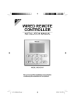
BRC1C62
3
C: 3P171361-1
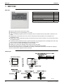
1. On/off button
Press the button and the system will start. Press the
button again and the system will stop.
2. Operation lamp (red)
The lamp lights up during operation.
3. Display “
” (changeover under control)
It is impossible to changeover heat/cool with the remote
controller which display this icon.
4. Display “
” (air flow flap)
5. Display “
” (ventilation/air cleaning)
This display shows that the ventilation unit are in
operation. (these are optional accessories)
6. Display “
C ” (set temperature)
This display shows the temperature you have set.
7. Display “
”“
”“
”“
”“
” (operation
mode)
This display shows the current operation mode.
8. Display “
” (programmed time)
This display shows the programmed time of the system
start or stop.
TEST ” (inspection/test operation)
9. Display “
When the inspection/test operation button is pressed,
the display shows the mode in which the system
actually is.
10. Display “
” (under centralized control)
When this display shows, the system is under
centralized control. (This is not a standard
specification.)
11. Display “
” (fan speed)
This display shows the fan speed you have selected.
12. Display “
” (time to clean air filter)
13. Display “
” (defrost/hot start)
14. Timer mode start/stop button
15. Timer on/off button
16. Inspection/test operation button
This button is only used by qualified service persons for
maintenance purposes.
17. Programming time button
Use this button for setting the programming start and/or
stop time.
18. Temperature setting button
Use this button for setting the desired temperature.
19. Filter sign reset button
Refer to the operation manual of indoor unit.
20. Fan speed control button
Press this button to select the fan speed of your
preference.
21. Operation mode selector button
Press this button to select the operation mode of your
preference.
22. Air flow direction adjust button
23. Thermistor
It sense the room temperature around the remote
controller.
24. These button are used when the ventilation unit are
installed (These are optional accessories)
Refer to the operation manual of the ventilation unit.
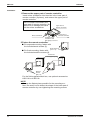
NOTE
•
•
•
In contradistinction to actual operating situations, the
display on figure 1 shows all possible indications.
Above figure shows the remote controller which is
opened the cover.
If that particular function is not available, pressing the
button may display the words “NOT AVAILABLE” for a
few seconds.
When running multiple units simultaneously the “NOT
AVAILABLE” message will only be appear if none of the
indoor units is equipped with the function. If even one
unit is equipped with the function, the display will not
appear.
C:3P171361-1
Wired Remote Controller
51