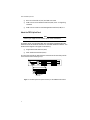
1
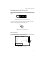
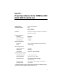
AT-8202 AT-8203 ATM and FDDI Uplink and Accelerator Cards For the FORMULA 8200™ Fast Ethernet Workgroup Switch Installation Guide PN 613-10660-00 Rev. A Copyright 1998 Allied Telesyn International Corp. All rights reserved. No part of this publication may be reproduced without prior written permission from Allied Telesyn International Corp. FORMULA 8200 is a trademark of Allied Telesyn International Corp. Ethernet is a registered trademark of Xerox Corporation. All other product names, company names, logos or other designations mentioned herein are trademarks or registered trademarks of their respectives owners. Allied Telesyn International Corp. reserves the right to make changes in specifications and other information contained in this document without prior written notice. The information provided herein is subject to change without notice. In no event shall Allied Telesyn International Corp. be liable for any incidental, special, indirect, or consequential damages whatsoever, including but not limited to lost profits, arising out of or related to this manual or the information contained herein, even if Allied Telesyn International Corp. has been advised of, known, or should have known, the possibility of such damages. Electrical Safety and Installation Requirements STANDARDS: This product meets the following standards. U.S. Federal Communications Commission RADIATED ENERGY Note: This equipment has been tested and found to comply with the limits for a Class A digital device pursuant to Part 15 of the FCC Rules. These limits are designed to provide reasonable protection against harmful interference when the equipment is operated in a commercial environment. This equipment generates, uses, and can radiate radio frequency energy and, if not installed and used in accordance with this instruction manual, may cause harmful interference to radio communications. Operation of this equipment in a residential area is likely to cause harmful interference in which case the user will be required to correct the interference at his own expense. Note: Modifications or changes not expressly approved by the manufacturer or the FCC can void your right to operate this equipment. Canadian Department of Communications This Class A digital apparatus meets all requirements of the Canadian InterferenceCausing Equipment Regulations. Cet appareil numérique de la classe A respecte toutes les exigences du Règlement sur le matériel brouilleur du Canada. RFI Emission EN55022 Class A WARNING: In a domestic environment this product may cause radio interference in which case the user may be required to take adequate measures. Immunity EN50082-1 SAFETY ELECTRICAL NOTICES WARNING: ELECTRIC SHOCK HAZARD To prevent ELECTRIC shock, do not remove cover. No user-serviceable parts inside. This unit contains HAZARDOUS VOLTAGES and should only be opened by a trained and qualified technician. To avoid the possibility of ELECTRIC SHOCK, disconnect electric power to the product before connecting or disconnecting the LAN cables. This is a “CLASS 1 LED PRODUCT.” LIGHTNING DANGER DANGER: DO NOT WORK on equipment or CABLES during periods of LIGHTNING ACTIVITY. iii Electrical Safety and Installation Requirements INSTALLATION ELECTRICAL—AUTO VOLTAGE ADJUSTMENT This product will automatically adjust to any voltage between the ranges shown on the label. ELECTRICAL—TYPE CLASS 1 EQUIPMENT THIS EQUIPMENT MUST BE EARTHED. Power plug must be connected to a properly wired earth ground socket outlet. An improperly wired socket outlet could place hazardous voltages on accessible metal parts. ELECTRICAL—CORD NOTICE Use power cord, maximum 4.5 meters long, rated 6 amp minimum, 250V, made of HAR cordage molded IEC 320 connector on one end and on the other end a plug approved by the country of end use. CAUTION: Air vents must not be blocked and must have free access to the room ambient air for cooling. CAUTION: DO NOT detach rubber feet from the product unless an Allied Telesyn vertical mounting chassis is being used. ALL COUNTRIES: Install product in accordance with local and National Electrical Codes. iv Table of Contents Electrical Safety and Installation Requirements .................................. iii Uplink Card Installation ...............................................................................1 Who Should Use This Guide ...............................................................................1 About the ATM Uplink Card ..............................................................................1 About the FDDI Uplink Card .............................................................................2 Verifying Your Uplink Package ..........................................................................4 Prerequisites for Card Installation ....................................................................4 Installing the Uplink Card..................................................................................5 Installing the Accelerator Card ..........................................................................9 Replacing the Chassis Top Cover .....................................................................10 Initializing the Switch.......................................................................................11 Interpreting the LEDs.......................................................................................12 Cabling Requirements for the FDDI Uplink Card ..........................................13 SAS Cable Connections..............................................................................13 DAS Cable Connections .............................................................................14 Optical Bypass Connector..........................................................................14 Where to Go From Here ....................................................................................15 In Case of Problems...........................................................................................15 Appendix A Product Specifications for the FORMULA 8200 Switch With the Uplink Card ...............................................................................17 Appendix B Technical Support Fax Order ....................................................................19 Incident Summary.............................................................................................19 Appendix C FORMULA 8200 Uplink Card Installation Guide Feedback ...............21 Appendix D Where To Find Us ..........................................................................................23 v Uplink Card Installation This guide shows you how to install: ❑ One of the following uplink cards in the lower PCI slot of the FORMULA 8200 switch: — ATM uplink card, model AT-8202 — FDDI uplink card, model AT-8203 ❑ The accelerator card in the upper PCI slot The accelerator card provides improved performance to the uplink card and switch. Who Should Use This Guide This guide is written for technical personnel responsible for installing the uplink and accelerator cards in the FORMULA 8200 switch, installing the switch, and connecting devices to its ports. Installers must be familiar with Ethernet, Fast Ethernet, and ATM or FDDI technology. About the ATM Uplink Card The ATM uplink card connects your Ethernet networks with high-speed and capacity of ATM networks, providing connectivity between servers, workgroups, workstations, and ATM backbones. The ATM uplink card supports the following ATM key functions: ❑ 155 Mbps, OC-3c/STM-1 data rate ❑ Switched virtual circuit (SVC) or permanent virtual circuit (PVC) connections, including trunking and point-to-point (PTOP) connections ❑ ATM Forum’s LAN Emulation Client (LEC) standard 1 About the FDDI Uplink Card ❑ RFC 1577 Classical IP (CIP) and ARP over ATM ❑ ATM Forum’s User Network Interface (UNI) 3.0 or 3.1 signaling standard ❑ ATM Forum’s Interim Local Management Interface (ILMI) 1.0 About the FDDI Uplink Card Note Contact your supplier for the FDDI uplink card’s availability. The FDDI uplink card provides fiber optic connectivity between switched Ethernet and Fast Ethernet networks an and FDDI backbone network. The FDDI module supports two types of connectivity: ❑ Single-attachment stations (SAS) ❑ Dual-attachment stations (DAS) The card also includes an optical bypass connector and LEDs that provide visual status of the card (Figure 1). LEDs Port B Port A Optical Bypass Connector Figure 1: The FDDI Uplink Card (Model AT-8203) in the FORMULA 8200 Switch 2 AT-8202 and AT-8203 Installation Guide As shown in Figure 2, the FDDI uplink allows workstations on Ethernet and Fast Ethernet networks to reach remote systems across a fiber optic backbone ring network. FDDI Concentrator DAS SAS 10/100BASE-T NETWORK PORTS 10/100BASE-T NETWORK PORTS 91 10 2 11 3 10/100BASE-T NETWORK PORTS 10/100BASE-T NETWORK PORTS 12 4 13 5 GREEN - LINK YELLOW - DIAG GREEN - ACTIVITY YELLOW - COLLISION GREEN - LINK YELLOW - DIAG GREEN - ACTIVITY YELLOW - COLLISION 10/100BASE-T NETWORK PORTS 1 RESET 2 3 14 6 15 7 16 8 10/100BASE-T NETWORK PORTS 4 5 6 7 8 8201 FORMULA 8200 STATUS FORMULA 8200 10/100BASE-T NETWORK PORTS 10/100BASE-T NETWORK PORTS 91 10 2 11 3 10/100BASE-T NETWORK PORTS 10/100BASE-T NETWORK PORTS 12 4 13 5 GREEN - LINK YELLOW - DIAG GREEN - ACTIVITY YELLOW - COLLISION GREEN - LINK YELLOW - DIAG GREEN - ACTIVITY YELLOW - COLLISION 10/100BASE-T NETWORK PORTS 1 RESET POWER 2 3 14 6 15 7 16 8 8201 10/100BASE-T NETWORK PORTS 4 5 6 7 8 STATUS POWER RS-232 TERMINAL PORT RS-232 TERMINAL PORT Figure 2: The FORMULA 8200 in an FDDI Network Remote systems can be network file servers, workstations, FDDI concentrators, switches, or routers running compatible TCP/IP software. The FDDI uplink module supports IP and ARP packets over FDDI networks, as described in RFC 1390. The following features are supported by the FDDI uplink module: ❑ Asynchronous LLC frames for downlink bridging ❑ Ethernet Type II, IEEE 802.3 SNAP packets for uplink capability (protocol sensitive) ❑ Translational bridging between FDDI and Ethernet ❑ IP and ARP frame encapsulation (RFC 1042 and RFC 1390) ❑ IP fragmentation (RFC 791) ❑ 802.1d Spanning Tree algorithm ❑ 64 CAM entries with aging algorithm for MAC address filtering ❑ Standard FDDI MIB support using SNMP, as well as SMT 7.3 support ❑ Configuration through command-line interface ❑ Board status LEDs ❑ Two SC (fiber optic) connectors supporting both DAS and SAS configurations ❑ Optical bypass connector 3 Verifying Your Uplink Package Verifying Your Uplink Package Your uplink card package consists of: ❑ This installation guide ❑ One of the following cards: — 155 Mbps ATM uplink OC-3 MMF card (model AT-8202), or — FDDI uplink card (model AT-8203) ❑ One accelerator card ❑ Warranty card If any of these components are damaged, contact your shipping carrier representative. If any components are missing, please phone the Allied Telesyn. Refer to Appendix D, “Where To Find Us,” on page 23. Prerequisites for Card Installation Before installing the uplink and accelerator cards, make sure you have the following: ❑ An installed FORMULA 8200 switch and that it is functioning properly ❑ Firmware version 1.4.3 or greater to support the uplink and accelerator cards If your switch does not have the latest firmware, download it from Allied Telesyn’s FTP server. See Appendix D, “Where To Find Us” on page 23, for information on how to access the server. 4 AT-8202 and AT-8203 Installation Guide Installing the Uplink Card Caution Prior to installing the uplink card, make sure you have successfully installed the FORMULA 8200 switch with firmware version 1.4.3 or greater, and that it is functioning properly. You will need a #1 Phillips screwdriver for this procedure. To install the uplink card in the FORMULA 8200, use the following steps: 1. Turn off power to the FORMULA 8200. The power switch is located on the rear panel of the chassis, as shown in Figure 3. ➂ ➀ ➁ Status Power Reset Key: 1 Accelerator cover plate 2 Uplink card cover plate ➃ ° 3 Switch top cover 4 Power switch (located on the back of switch) Figure 3: FORMULA 8200 Front Panels and Power Switch 2. Unplug the unit. When installing or removing cards in a switch, always remove all power by unplugging the unit. 3. Disconnect and label all connections to the switch, if present. To install the uplink card, you must take the top cover off of the switch. To remove the top cover, it may be necessary to remove the switch from the rack or tabletop location. 5 Installing the Uplink Card 4. Remove additional hardware, such as rackmounting brackets. Note If the switch is installed on the desktop, you need not remove the rubber feet. Warning Use proper static-free procedures prior to opening the unit and touching components. 5. Remove the top cover from the unit, as follows: a. Remove the screw from the back of the unit that locks the cover in place. Retain the screw for replacing the cover later. b. Lift the cover and slide it off (Figure 4). Figure 4: Chassis Top Removal 6. Using a #1 Phillips screwdriver, remove the screw that secures the cover plate to the uplink panel (Figure 5). Save the screw to secure the uplink card. 6 AT-8202 and AT-8203 Installation Guide Figure 5: Cover Plate Removal 7. Install the uplink card into the lower PCI slot (Figure 6). Ensure that the uplink card is fully seated in the lower PCI slot. Align the back edge of the board in the card guide as you are installing it. Figure 6: Uplink Card Insertion Caution The uplink card will not function if it is installed into the upper PCI slot. The upper PCI slot is intended for the accelerator card only. 7 Installing the Uplink Card 8. Using the screw from Step 6, secure the uplink card to the chassis (Figure 7). Figure 7: Uplink Card Attachment to Chassis 9. 8 Proceed immediately to the next sections to install the accelerator card, replace the cover, and then re-initialize the switch. AT-8202 and AT-8203 Installation Guide Installing the Accelerator Card Before following these procedures, make sure the uplink card is already installed in the lower slot. 1. Using a #1 Phillips screwdriver, remove the screw that secures the cover plate to the uplink panel (Figure 8). Figure 8: Cover Plate Removal for Top PCI Slot 2. Insert the accelerator card into the top PCI slot and ensure that it is fully seated. Line up the back edge of the accelerator card with the card guide, as shown in Figure 9. Figure 9: Accelerator Card Insertion 3. Seat the accelerator card firmly in the top PCI connector. 4. Using the screw from Step 1, secure the accelerator card to the chassis. 9 Replacing the Chassis Top Cover Replacing the Chassis Top Cover 1. Slip the back of the cover over the back chassis rails, as shown in Figure 10. AC-4003 Figure 10: Chassis Top Cover Replacement 10 2. Lower the cover onto the chassis, being careful to align the latches along the chassis sides with the latch cutouts on the cover. 3. Once the cover is in position, gently push it forward toward the front bezel until it latches into position. 4. Secure the cover by inserting and tightening the original screw you removed from the back when you took the cover off in Step 5 on page 6. 5. Reattach rackmount brackets if applicable, and return the unit to the rack, bench, or table. AT-8202 and AT-8203 Installation Guide Initializing the Switch 1. Connect a terminal to the switch’s console port so you can monitor the boot process. Refer to your FORMULA 8200 Installation Guide for the procedures. 2. Apply power to the switch. The switch firmware runs post diagnostics where it decompresses data and loads it into the DRAM. The process takes about 15 to 20 seconds. During switch initialization, watch for the following messages that indicate the successful installation of the uplink and accelerator cards: Attaching network interface lo0... done. Initializing accelerator... done. 3. Reattach the network cables to the ports, one at a time, beginning with the leftmost port. Observe that port’s LED to ensure normal operations; then, attach the cable to the next port. Attaching the cables one at a time and ensuring link stability helps you isolate problems in case some links may have problems. This completes the uplink card and accelerator card hardware installation. 11 Interpreting the LEDs Interpreting the LEDs The ATM uplink card has one link LED. If there is a valid link, the LED is solid green. If the uplink card is not connected to any device, or there is a problem with the link, the LED is off. The FDDI uplink card has two LEDs. Table 1 provides information about what the LEDs mean in various states. Table 1: FDDI LED States LED Status Board Status Description Yellow Green Off Off Fail Adapter card is not functional, or driver is not loaded. Call Allied Telesyn’s Technical Support. Off On Ring Op Ring operation THRU B (DAS) wrap S for SAS On Off Cable Error Adapter card is unable to connect; there is a possible cable problem. Fix the cable problem. On On Ring Op/ Wrapped Ring operation: wrap A or B (DAS), unused for SAS 12 AT-8202 and AT-8203 Installation Guide Cabling Requirements for the FDDI Uplink Card The FDDI uplink card provides two dual SC connector ports (Figure 11). These ports allow both SAS and DAS configurations. Use 62.5/125 micron multimode cables. Port B Port A Figure 11: FDDI Uplink Card’s Dual SC Connector Ports You can attach a plastic clip to hold the cable ends (see Figure 12) for easy connection and disconnection on the FDDI uplink card. Figure 12: Plastic Clip for FDDI Connectors SAS Cable Connections For a SAS configuration, connect Port A of the FDDI Uplink module to the M port of an FDDI concentrator, as shown in Figure 13. To FDDI Network SAS Cabling SC Port A A B M M M M M Dual Attached Concentrator Figure 13: SAS Cable Connection 13 Cabling Requirements for the FDDI Uplink Card DAS Cable Connections For a DAS configuration, connect Port A and Port B to their corresponding ports at the host, as shown in Figure 14. DAS B A Upstream Downstream FDDI DAS Device A B B A FDDI DAS Device Figure 14: DAS Cable Connections Optical Bypass Connector The FDDI uplink card provides a standard optical bypass connector for installation of an optical bypass relay, if you choose to use one. See Figure 15. Optical Bypass Connector Figure 15: Optical Bypass Connector The optical bypass connector must be a DIN connector. For additional information about installing or using an optical bypass connector, refer to the instructions provided by your optical bypass relay manufacturer. 14 AT-8202 and AT-8203 Installation Guide Where to Go From Here To configure, operate, and monitor the switch, download the following guides from Allied Telesyn’s website at www.alliedtelesyn.com/manuals.htm: ❑ Software Release Notes for information on your version of switch firmware ❑ AT-8202 ATM Uplink User’s Guide for ATM-specific commands ❑ AT-8203 FDDI Uplink User’s Guide for FDDI-specific commands ❑ FORMULA 8200 User’s Guide for Ethernet commands In Case of Problems The uplink cards provide transparent operation once they have been installed and configured. If you suspect that the card you have installed is malfunctioning or is causing system problems, refer to the LEDs for the card’s operational status. Refer also to the switch’s system and port LEDs to further isolate the problem. If you are unable to resolve the problem, contact Allied Telesyn’s Technical Support. See Appendix D, “Where To Find Us” on page 23, for contact information. 15 Appendix A Product Specifications for the FORMULA 8200 Switch With the Uplink Card Network Protocol Ethernet and Fast Ethernet Standards Supported 802.1d 802.3i, 10Base-T 802.3u, 100Base-T Data Rate ATM uplink: 155 Mbps, OC-3c/STM1 multimode fiber FDDI uplink: 100 Mbps Hardware Architecture Processor MIPS 4650 Flash memory 2 Mbytes Processor DRAM 8 Mbytes Physical Specifications Dimensions Weight 3.5”H x 17” W x 18”D (8.97 x 43.6 x 46.2 cm) 19 lbs (8.6 kg) Electrical Specifications Input line frequency 47-63 Hz Input voltage 90-264 VAC, auto-selectable Input current 3-6 Amps Environmental Specifications Operating temperature 0˚ to 40˚ C (32˚ to 104˚ F) Storage temperature –20˚ to 60˚ C (–18˚ to 148˚ F) Operating humidity 85% maximum relative humidity, noncondensing Storage humidity 95% maximum relative humidity, noncondensing Operating altitude 0 to 10,000 ft. For Electromagnetic Immunity, Electromagnetic Emissions, and Safety Agency Approvals, see the FORMULA 8200 Installation Guide. 17 Appendix B Technical Support Fax Order Name___________________________________________________________________ Company ________________________________________________________________ Address _________________________________________________________________ City ________________________ State/Province ________________________________ Zip/Postal Code ___________________ Country ________________________________ Phone _______________________________ Fax ________________________________ Incident Summary Model number of Allied Telesyn product I am using ______________________________ Network software products I am using _________________________________________ _______________________________________________________________________ Brief summary of problem __________________________________________________ _______________________________________________________________________ Conditions (list the steps that led up to the problem) _____________________________ _______________________________________________________________________ _______________________________________ _______________________________ Detailed description (use separate sheet, if necessary) _______________________________________________________________________ _______________________________________ _______________________________ _______________________________________________________________________ When completed, fax this sheet to the appropriate Allied Telesyn office. Fax numbers can be found on page 23. 19 Appendix C FORMULA 8200 Uplink Card Installation Guide Feedback Please tell us what additional information you would like to see discussed in the guide. If there are topics you would like information on that were not covered in the guide, please photocopy this page, answer the questions and fax or mail this form back to Allied Telesyn International Corp. The mailing address and fax number are at the bottom of the page. Your comments are valuable when we plan future revisions of the guide. I found the following the most valuable __________________________________ ______________________________________________________________________ ______________________________________________________________________ ______________________________________________________________________ ______________________________________________________________________ I would like the following more developed ________________________________ ______________________________________________________________________ ______________________________________________________________________ ______________________________________________________________________ ______________________________________________________________________ I would find the guide more useful if ____________________________________ ______________________________________________________________________ ______________________________________________________________________ ______________________________________________________________________ Please fax or mail your feedback. Fax to 1-425-481-3790. Or mail to: Allied Telesyn Technical Communications Department 19015 North Creek Parkway Bothell, WA 98011 USA 21 Appendix D Where To Find Us For Technical Support or Service Location Phone Fax Americas United States, Canada, Mexico, Central America, South America 1 (800) 428-4835 1 (425) 481-3790 Asia Singapore, Taiwan, Thailand, Malaysia, Indonesia, Korea, Philippines, China, India (+65) 3815-613 (+65) 3833-830 Australia Australia, New Zealand (612) 416-0619 (612) 416-9764 France France, Belgium, Luxembourg, The Netherlands, Middle East, Africa (+33) 1-60-92-15-32 (+33) 1-69-28-37-49 Germany Germany, Switzerland, Austria, Eastern Europe (+49) 30-435-900-126 (+49) 30-435-70-650 Hong Kong (+852) 2-529-4111 (+852) 2 529-7661 Italy Italy, Spain, Portugal, Greece, Turkey, Israel (+39) 2-416047 (+39) 2-419282 Japan (+81) 3-3443-5640 (+81) 3-3443-2443 United Kingdom United Kingdom, Denmark, Norway, Sweden, Finland, Iceland (+44) 1-235-442560 (+44) 1-235-442490 Technical Bulletin Board Service 1 (425) 483-7979 Technical Support E-mail Address [email protected] CompuServe Go ALLIED World Wide Web http://www.alliedtelesyn.com FTP Server Address: ftp.alliedtelesyn.com [lowercase letters] Login: anonymous [lowercase letters] Password: your e-mail address [requested by the server at login] For Information Regarding Allied Telesyn International Allied Telesyn International 19015 North Creek Parkway Bothell, WA 98011 Tel: 1 (425) 487-8880 Fax: 1 (425) 489-9191 Allied Telesyn International 950 Kifer Road Sunnyvale, CA 94086 Tel: 1 (800) 424-4284 (USA and Canada) Fax: 1 (408) 736-0100 23 Where To Find Us For Sales Information Australia United States Lindfield, NSW Tel: (612) 416-0619, Fax: (612) 416-9764 Scottsdale, AZ Tel: (602) 423-7087 Fax: (602) 423-7088 Los Angeles, CA Tel: (310) 412-8684, Fax: (310) 412-8685 Mission Viejo, CA Tel: (714) 699-0628, Fax: (714) 699-0276 San Diego, CA Tel: (619) 279-3899, Fax: (619) 279-3897 Santa Ana, CA Tel: (714) 838-0434, Fax: (714) 838-9721 Clearwater, FL Tel: (813) 726-0022, Fax: (813) 726-0234 Norcross, GA Tel: (770) 448-7214, Fax: (770) 448-2600 Reading, MA Tel & Fax: (617) 944-3492 Eden Prairie, MN Tel: (612) 829-7506, Fax: (612) 903-5284 St. Louis, MO Tel: (314) 894-6160, Fax: (314) 894-3773 Dover, NH Tel: (603) 743-3010, Fax: (603) 743-6327 Plaistow, NH Tel: (603) 382-0815, Fax: (603) 382-0818 Portsmouth, NH Tel: (603) 431-6461, Fax: (603) 431-1649 Morrisville, NC Tel: (919) 468-0831, Fax: (919) 468-0829 Lake Oswego, OR Tel: (503) 699-3130, Fax: (503) 636-6575 Austin, TX Tel: (512) 261-6378, Fax: (512) 261-6379 Dallas, TX Tel: (214) 365-9471, Fax: (214) 365-9472 San Antonio, TX Tel: (210) 646-8744 Vienna, VA Tel: (703) 506-0196, Fax: (703) 506-1986 Canada Rexdale, Ontario Tel: (416) 675-6738, Fax: (416) 675-0057 Richmond, British Columbia Tel: (604) 244-0678, Fax: (604) 270-3644 England Abingdon, Oxon Tel: (+44) 1235-442500, Fax: (+44) 1235-442590 France Les Ulis Tel: (+33) 1-60921525, Fax: (+33) 169-28-37-49 Germany Berlin Tel: (+49) 30-435-90-00, Fax: (+49) 30-435-706-50 Freising Tel: (+49) 8161-9906-0, Fax: (+49) 8161-9906-22 Hong Kong Mongkok Tel: (+852) 2-529-4111, Fax: (+852) 2-529-7661 Italy Milano Tel: (+39) 2-416047, Fax: (+39) 2-419282 Japan Machida-shi, Tokyo Tel: (+81) 427-21-8141, Fax: (+81) 427-21-8848 Yodogawa-ku, Osaka Tel: (+81) 6-391-6310, Fax: (+81) 6-391-6325 Singapore Tel: (+65) 383-3832, Fax: (+65) 383-3830 24