1
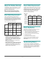
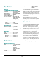
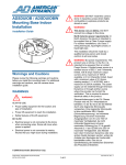
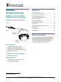
RHODUL
Outdoor Housing
Contents
RHODUL-03 with Clear Bubble
RHODUL-04 with Smoked Bubble
Data Cable Requirements......................................2
About this Guide.....................................................1
About the Outdoor Housing ...................................2
Power Cable Requirements ...................................2
Power-Up Routine..................................................2
Installation and Service Guide
Synchronizing Domes ............................................2
Warnings and Cautions .........................................3
Figure 1
Procedure ..............................................................5
Troubleshooting Outdoor Domes...........................9
Ordering Parts...................................................... 12
Specifications ....................................................... 14
Declarations ......................................................... 14
Pigtail
Housing
Assembly
About this Guide
This guide explains how to install the RHODUL
outdoor housing. It does not explain how to install
the outdoor mounting structure to which the
housing is attached. For this information, see
information shipped with the structure.
Bubble
Assembly
Parts Supplied
·
·
·
·
Housing assembly 0100-2468-01
Bubble assembly 0400-1402-01/-02
Tamperproof drive (supplied with bubble)
Install kit 0351-2183-01
Purchase or Supply Separately
· Male BNC connector
Tools Required
· 1/4" fixed-handle nut driver for Torx bit
· Wire cutters and strippers
© Sensormatic 2001
RHODUL OUTDOOR HOUSING INSTALLATION AND SERVICE GUIDE (8000-2830-05, REV. A)
1 of 14
About the Outdoor Housing
Power Cable Requirements
The RHODUL outdoor housing (Figure 1) is used
to attach the SpeedDome Ultra camera dome to
an outdoor mounting structure.
Note: This guide assumes that a mounting
structure is in place and that data and power
cables have been pulled to the installation site.
Length of power cable between a Class 2 LPS (low
voltage) ac source, such as a J-box, and the dome
depends on the ac line voltage. See Table 2 below
for cable lengths based on worst case low line
voltages for Japan (100Vac), North America
(120vac), and Europe (240vac).
Data Cable Requirements
Worst Case
Line
Voltages
18AWG
16AWG
14AWG
90 Vac
(Japan)
30m (100')
50m (160')
80m (260')
102 Vac
(N. Amer.)
60m (200')
100m (320')
160m (520')
180 Vac
(Europe)
30m (100')
50m (160')
80m (260')
204 Vac
(Europe)
60m (200')
100m (320')
160m (520')
Table 1 shows data cable requirements for
SensorNet, RS422, and Manchester networks. For
more information about communication protocols
and cable networks, see Communication Protocols
and Cable Networks, 8000-2573-19.
Table 1. Data cable requirements
SensorNet
RS422
Manchester
Cable
type
1
unshielded,
twisted pair*
2
shielded,
twisted
pair*
1
shielded
twisted pair**
Wire
gauge
22 AWG
22 AWG
18 AWG
Connection
Nonpolarized
Polarized
Polarized
Max.
devices
on line
32
10
3
Power-Up Routine
After power is connected to the dome, the dome
performs the following homing routine.
1. After a few seconds, the camera lens tilts up
into the housing and eyeball assembly.
2. The lens tilts downs until it looks at the floor.
3. Eyeball pans slowly.
4. Lens tilts up 90° (home position).
*
Power, data, and video cables can be ordered
separately or within a composite cable that can be
ordered in various lengths. All cables must be
plenum rated for indoor installations where cable is
routed above the ceiling. Order parts through your
distribution network.
Note: If you order cable from an outside source,
wire colors may be different.
** Belden 88760 (plenum), or Belden 8760 cable (nonplenum) cable is recommended. Plenum-rated cable
is required for indoor installations where cable is
routed above the ceiling. Order cable directly from
Belden by calling 1-800-235-3361.
Once the lens is in its home position, you can
then use the controller to call up the camera
and control it.
Synchronizing Domes
To prevent picture rolling when switching from
camera to camera, all domes can be synchronized
to a 50Hz or 60Hz ac source. A V-phase adjustment at the control console enables the dome to
sync to any line phase.
RHODUL OUTDOOR HOUSING INSTALLATION AND SERVICE GUIDE (8000-2830-05, REV. A)
2 of 14
Warnings and Cautions
!
Please review the following warnings and cautions
before you begin installation or service.
WARNINGS
!
WARNING!
ALWAYS USE:
· Proper safety equipment for the
location and type of installation.
· Proper lift equipment to reach the
installation.
Stromanforderungen in der EU: Dieses
Produkt wird mit 24 V Wechselstrom
betrieben. In der EU ist es für den Betrieb
durch eine begrenzte Stromquelle
vorgesehen. Eine begrenzte Stromquelle
ist eine zertifizierte SELV-Quelle
(Schutzkleinspannung), bei inhärenter
Begrenzung mit einem maximalen
Ausgangsstrom von 8 A und 100 VA
maximaler Verfügbarkeit, bei nicht
inhärenter Begrenzung mit einer
maximalen Sicherung von 3,3 A gemäß
Abschnitt 2.11 der IEC950 und 250 VA
maximaler Verfügbarkeit. Das Netzteil
kann über Sensormatic oder eine andere
Quelle bezogen werden, wobei der
Anbieter den Nachweis der Konformität
bereitstellen sollte. Dies ist zur
Gewährleistung der elektrischen Sicherheit
des Produktes erforderlich.
· Safety features of the lift equipment.
BE SURE:
· Electrical power is not connected to the
dome when connecting wires. Dome
will move when power is applied.
· Electrical power is not connected to
nearby fixtures that you might touch
during installation.
!
WARNING!
EU power requirements: This product
runs on 24Vac. In the EU, it is intended to
be powered from a Limited Power Source.
A limited power source is a certified source
of SELV, and if inherently limited, with 8
amps maximum output current, and a
maximum of 100VA available; or if not
inherently limited, fused with a maximum
value of 3.3 Amps, meeting section 2.11 of
IEC950, and a maximum of 250VA
available. The power supply can be
obtained through Sensormatic or through
another source where the provider can
furnish the verification. This is required to
assure electrical safety in the product.
WARNING!
This dome runs on 24Vac. DO NOT
connect line voltage to this dome.
North America power requirements: In
North America, this device is intended to
be supplied from a Class 2 power supply.
For outdoor installations, use Class 3
wiring techniques, liquid-tight conduit, or
liquid-tight pipe.
This installation should be made by a
qualified service person and should
conform to all local codes.
!
WARNING!
DO NOT install this housing in hazardous
areas where highly combustible or
explosive products are stored or used.
RHODUL OUTDOOR HOUSING INSTALLATION AND SERVICE GUIDE (8000-2830-05, REV. A)
3 of 14
CAUTIONS
The outdoor housing contains an environmental
PC board. Touch the metal housing to
discharge static electricity before touching this
board. Also, use a jeweler’s 2.5mm (0.1")
slotted screwdriver to tighten PC board
connectors. Wider blade widths can damage
connectors. Do not over tighten connectors.
You should have two boxes: one for the outdoor
housing, the other for the bubble assembly.
Protect the bubble assembly by leaving it in its
box until you are ready to install it.
Do not run data and power cables adjacent to
or in the same conduit as line voltage mains
power.
When connecting the housing and eyeball
assembly to the outdoor housing:
- Remove both slot covers to keep the
camera from overheating
SensorNet 485 networks require 22 AWG
unshielded cable. Do not exceed 32 devices
per cable run.
- Keep cables entering the housing away from
the heater assembly
RS422 networks require 22 AWG shielded
cable. Do not exceed 10 devices per cable run.
- Check heater fan operation. Both fans must
be on to prevent overheating.
Manchester networks require 18 AWG shielded
cable. Do not exceed 3 devices per cable run.
Always terminate the camera dome connected
at the end of a cable run.
RHODUL OUTDOOR HOUSING INSTALLATION AND SERVICE GUIDE (8000-2830-05, REV. A)
4 of 14
4. Connect data to 6-pin connector on pigtail.
Procedure
Note: Wire colors are for composite cable only.
IMPORTANT! To minimize trips up and down
ladder, review procedure first before attempting to
attach outdoor housing. Lay out and prepare parts
accordingly.
Manchester data connections. Order data
cable 88760 (plenum) or 8760 (non-plenum)
from Belden by calling 1-800-235-3361.
Pin
Attaching the Housing to the
Outdoor Mounting Structure
!
Color
Designation
1-4
—
5
Black
Manchester (+)
Not used.
6
White
Manchester (–)
RS422 Data connections
WARNING! Turn power off at the source
before beginning this procedure.
Pin
Color
1
Orange
RS422 Data In High (+)
2
Green
RS422 Data In Low (–)
3
Yellow
RS422 Data Out High (+)
4
Brown
RS422 Data Out Low (–)
5-6
—
1. If a “Street L” pipe or elbow is attached to pipe
of mounting structure, replace it with the end
cap shown below (Figure 2). Refer to End Cap
Installation Guide, 8000-2692-04.
Note: A Street L is like an elbow, except that
one end is female and the other end is male
(which does not mate with the housing).
Designation
Not used.
SensorNet Data Connections
Figure 2. End cap
End Cap
Pin
Color
Designation
1-4
—
Not used.
5
Brown
SensorNet (unshielded)
6
Yellow
SensorNet (unshielded)
5. Connect alarm input, if used, to 5-pin connector
on pigtail.
2. Connect ac wires to 3-pin plug on pigtail.
Pin
Color
1
N/A
24 Vac
2
N/A
Common
3
N/A
24 Vac
Pin
Color
Designation
1
N/A
Alarm input (3.5mA sink)
2
N/A
Ground
Description
6. Connect relay output, if used, to 5-pin connector
pigtail.
3. Connect BNC connector to pigtail video input.
Pin
Color
1
N/A
Description
Normally Open (3.5mA sink)
2
N/A
Common
3
N/A
Normally Closed
7. Apply power to camera dome.
RHODUL OUTDOOR HOUSING INSTALLATION AND SERVICE GUIDE (8000-2830-05, REV. A)
5 of 14
Setting Line Termination
8. Check LEDs on environmental board to verify
power and data are reaching outdoor housing
(Figure 3).
a. Press and hold switch SW2 and observe
green (ac power) and yellow (comm.)
LEDs. Green LED glows steadily and
yellow LED glows steadily (RS422) or
blinks (SensorNet).
For a SensorNet/Manchester communication line,
jumper JW1 on the environmental board is set at
the factory to “terminated” (when communication
lines do not continue). If the line is to continue to
another dome, use this procedure to set the
jumper to “unterminate”.
b. For RS422 data, press and hold data test
switch SW1 and observe nearby red and
green LEDs; they indicate the following:
CAUTION: This procedure requires that the
environmental PC board be detached from the
base. This board is static sensitive! Touch metal
housing to discharge static electricity.
Constant green,
Blinking red
RS422 line is
correctly wired.
Constant green,
No red
RS422 “Data In –” is
shorted to ground.
Constant red,
Blinking green
“Data In + /–” wires
are reversed.
Blinking red,
Green off
“Data In +” is shorted
to ground.
CAUTION: A dust cover protects the delicate
spring finger connector on the PC board. DO
NOT remove this cover until you have installed
the dome’s base.
Both LEDs off
“Data In +/–” wires
are shorted or open.
Figure 4. Detaching Environmental PC board
1. Detach the PC board by pushing the fingers
molded into the base away from the board while
pushing on the board with your index finger
(Figure 4).
Figure 3. Test switches
SW1
a
LEDs
SW2
LEDs
2. If comm. lines continue to another dome,
remove the jumper JW1 from across pins 2–3
and place it across pins 1–2 for “unterminated”.
3. Reattach the PC board to the base.
4. Gently remove the dust cover.
Note: Keep the cover for future use should you
need to ship the housing back to the
manufacturer.
RHODUL OUTDOOR HOUSING INSTALLATION AND SERVICE GUIDE (8000-2830-05, REV. A)
6 of 14
Attaching the Housing and
Eyeball Assembly
2. Set dome address (Figure 6).
Recessed at top of housing and eyeball
assembly are three rotary address switches.
Protocol address ranges are shown below.
Set switches from most significant bit (MSB) to
least significant bit (LSB). For example: For
address 166, set SW3 to 1, SW2 to 6, and
SW1 to 6.
Perform the following steps on the ground.
1. Remove SpeedDome Ultra housing and eyeball
assembly from box and remove BOTH slot
covers from eyeball (Figure 5).
!
WARNING! Proper ventilation
requires that the slot covers be
removed. Otherwise, camera
dome could overheat.
a. Gently swivel eyeball so a slot cover is
totally exposed.
CAUTION: Swiveling fast can damage
gears.
Address Range
SensorNet
1–255
Manchester
1–64
RS422
1–99
Figure 6. Setting address switches
b. Insert small slotted screwdriver into space
between cover and eyeball (Figure 5).
Gently pry slot cover loose.
SW3
MSB
CAUTION: Once slot covers are removed,
avoid touching lens of camera.
c.
Protocol
0
SW2
9 0
9 0
Gently swivel eyeball so remaining slot
cover is totally exposed. Lift cover off.
Figure 5. Removing slot covers
RHODUL OUTDOOR HOUSING INSTALLATION AND SERVICE GUIDE (8000-2830-05, REV. A)
7 of 14
SW1
LSB
9
Attaching the Trim Ring/
Bubble Assembly
3. Connect housing and eyeball assembly to the
base (Figure 7).
a. Align recessed dimple on cap of dome with
logo visible on environmental PC board.
Refer to Figure 8.
b. Mate housing and eyeball assembly to base
and turn it clockwise until you hear a click.
1. Remove bubble assembly from package and
ensure bubble is clean and free of debris.
After a few seconds, dome begins its
homing routine and heater fans are on.
This indicates that address was placed into
dome memory.
!
2. Attach coiled lanyard from bubble to
outdoor housing.
Attach lanyard to threaded stud on housing
using thumbnut [d].
WARNING! Heater fans must be
working! If either or both fans are off,
dome could overheat.
3. Attach trim bubble assembly.
a. Remove “CAUTION: Remove slot covers”
tag. Ensure slot covers are removed.
Figure 7. Attaching dome to base in outdoor
housing (align protusion on cap with
protrusion on base, then twist to lock)
b. Align key on inside of bubble assembly with
detent on edge of outdoor housing.
c.
Secure bubble assembly to housing using
four tamperproof screws. Use drive (taped
inside bubble) to tighten screws.
CAUTION: To maintain the integrity of the
gasket seal between the housing flange
and the trim ring, do not let the lanyard get
caught between these two pieces as you
secure the bubble assembly to the housing.
Figure 8. Attaching bubble assembly
Sun Shield
Align
Lock
LO C K
Key
Lanyard
Detent
(inside
bubble
assy.)
RHODUL OUTDOOR HOUSING INSTALLATION AND SERVICE GUIDE (8000-2830-05, REV. A)
8 of 14
Stud
3. Verify data is reaching housing.
Troubleshooting Outdoor
Domes
SENSORNET or RS422: Press and hold switch
SW2 on environmental PC board and observe
yellow (comm.) LED. Yellow LED should blink
(SensorNet) or glow steadily (RS422). For test
switch location, see Figure 3.
Perform the following procedures if one of the
following symptoms occur:
- Dome does not respond to commands
- Fans do not turn
- Picture grainy or discolored
- Poor video
- Ice forms on bubble.
To verify RS422 connections at connector P1,
press and hold data test switch SW1 on
environmental PC board. For test switch
location, see Figure 3. Observe nearby red and
green LEDs; they indicate the following:
Dome Does Not Respond to
Commands
Follow steps until the problem is corrected. See
page 12 to order parts.
1. Disconnect dome from base and examine
address switches.
Are they set correctly?
Constant green,
Blinking red
RS422 line is correctly
wired.
Constant green,
No red
RS422 “Data In –” is
shorted to ground.
Constant red,
Blinking green
“Data In + /–” wires are
reversed.
Blinking red,
Green off
“Data In +” is shorted to
ground.
Both LEDs off
“Data In +/–” wires are
shorted or open.
- YES: Continue.
- NO: Set correct address and reconnect
housing and eyeball assembly.
P1 pin outs:
Manchester data connections (Ultra IV only)
2. Verify power is reaching housing.
Press and hold switch SW2 on environmental
PC board and observe the green (ac power)
LED. Does green LED glow steadily?
Pin
- YES: Reconnect housing and eyeball
assembly and continue.
Connector P7 pin outs
Color
1
N/A
24 Vac
2
N/A
Common
3
N/A
24 Vac
Designation
—
Not used.
5
Black
Manchester (+)
6
White
Manchester (–)
RS422 Data connections
- NO: Check power at J-box and ac cable
connections at connector P7 on other side
of environmental PC board. If these items
are OK, replace environmental PC board.
Pin
Color
1-4
Description
Pin
Color
Designation
1
Orange
RS422 Data In High (+)
2
Green
RS422 Data In Low (–)
3
Yellow
RS422 Data Out High (+)
4
Brown
RS422 Data Out Low (–)
5-6
—
Not used.
CAUTION: Screws on ac connector are
delicate. DO NOT over tighten them! Use a
2.5mm (0.1") slotted screwdriver. Wider
blade widths can damage connectors.
RHODUL OUTDOOR HOUSING INSTALLATION AND SERVICE GUIDE (8000-2830-05, REV. A)
9 of 14
Fans Do Not Turn
SensorNet Data Connections
Pin
Color
Designation
1-4
—
Not used.
5
Brown
SensorNet (unshielded)
6
Yellow
SensorNet (unshielded)
Follow steps until the problem is corrected. See
page 12 to order parts.
1. Determine if housing and eyeball assembly
is receiving power.
Look for evidence such as a picture on the
video monitor or dome movement.
CAUTION: Screws on connector P1 are
delicate. DO NOT over tighten them! Use a
2.5mm (0.1") slotted screwdriver. Wider blade
widths can damage connectors.
2. Remove housing and eyeball assembly to
access environmental PC board.
Note: Power to fans comes from housing and
eyeball assembly. Fans will not function with
this assembly removed.
4. Check fans.
Are fans on?
- YES: Continue.
CAUTION: Touch metal housing before
handling environmental board.
- NO: Go to “Fans Do Not Turn” procedure
on page 10.
3. Verify power is reaching housing.
Press and hold switch SW2 and observe the
green (ac power) LED. Green LED should glow
steadily. If not, check power at J-box and ac
cable plugged into connector P7 on other side
of environmental PC board.
5. Check video on monitor.
Does picture roll on monitor?
- YES: Use video controller or switcher to
synchronize video vertical sync phases of all
domes to ac line. For specific instructions,
see installation and service manual for
controller or switcher.
CAUTION: Connector screws on ac connector
are delicate. DO NOT over tighten them! Use a
2.5mm (0.1") slotted screwdriver. Wider blade
widths can damage connectors.
- NO: Continue.
Is picture normal?
- YES: See “Detailed Troubleshooting” in
installation and service manual supplied with
housing and eyeball assembly.
4. Check fan connector.
Is fan connector on other side of environmental
PC board plugged into connector P5?
- NO: See “Poor or No Video” on page 11.
- YES: Replace fan/heater assembly 04000935-01. Remove two screws to remove
assembly. Refer to Figure 9.
- NO: Plug connector in, reinstall
environmental board, and reconnect
housing and eyeball assembly. If the fans
still do not work, replace the fan/heater
assembly.
RHODUL OUTDOOR HOUSING INSTALLATION AND SERVICE GUIDE (8000-2830-05, REV. A)
10 of 14
Picture Grainy or Discolored
Ice Forms On Bubble
Check the fans. If they are not turning, the camera
dome may be overheating. See “Dome Does Not
Respond to Commands” on page 10.
Follow steps until the problem is corrected. See
page 12 to order parts.
1. Verify that fans in housing are working.
If not, see “Fans Do Not Turn” on page 10.
Poor or No Video
2. Determine if housing and eyeball assembly
is receiving power.
Look for evidence such as a picture on the
video monitor or dome movement.
See “Dome Does Not Respond to Commands” on
page 9.
3. Remove housing and eyeball assembly to
access environmental PC board.
Note: Power to heater comes from housing and
eyeball assembly. Heater will not function with
this assembly removed.
CAUTION: Touch metal housing before
handling environmental board.
4. Verify power is reaching housing.
Press and hold switch SW2 and observe the
green (ac power) LED. Green LED should glow
steadily. If not, check power at J-box and ac
cable plugged into connector P7 on other side
of environmental PC board.
CAUTION: Connector screws on ac connector
are delicate. DO NOT over tighten them! Use a
2.5mm (0.1") slotted screwdriver. Wider blade
widths can damage connectors.
RHODUL OUTDOOR HOUSING INSTALLATION AND SERVICE GUIDE (8000-2830-05, REV. A)
11 of 14
5. Check heater connector.
Is heater connector on other side of environmental PC board plugged into connector P2?
Parts list
1
Cable Assy., Fan*
0650-2000-01
2
Heater*
0500-8023-01
3
Lanyard
0500-8797-01
4
Drive, Tamperproof
1400-0149-01
5
Nut, 1-1/2 NPT
6010-0100-01
6
Cover
0500-8001-01
7
Sun Shield
0500-7954-01
8
Nut, M6 (Qty. 4)
5826-0500-020
9
Washer (Qty. 4)
5840-0500-020
10
Support, Threaded
0500-9288-01
11
Gasket, Round
0500-9375-01
12
Housing
0500-7955-01
13
Thumbnut, M3
5899-0068-02
Ordering Parts
14
Bracket
0500-8054-01
15
Fan/Heater Assy.
0400-0935-01
This section helps you to identify parts that make
up the outdoor housing assembly. See table
opposite and Figure 9 for parts breakdown.
16
Screw, M3x8, PH (Qty. 2)
5801-1051-120
17
Base
0500-8049-01
18
Nut, M3 (Qty. 2)
5826-0200-020
19
Environ. PC Board w/Cable
0300-2484-01
20
Bubble Assy.
0400-1402
-01 (Clear)
-02 (Smoked)
21
Gasket
0500-9854-01
22
Bubble
0500-9318
-01 (Clear)
-02 (Smoked)
23
Trim Ring
0500-7956-02
24
Screw, Tamperproof (Qty. 4)
0500-8034-01
- YES: Unplug heater cable and check heater
resistance across pins of plug. Is resistance
approximately 16 ohms?
If OK, replace environmental PC board
0301-0949-01. If not, replace fan/heater
assembly 0400-0935-01 by removing two
screws. Refer to items 20 and 21 in
Figure 9.
- NO: Plug connector in, reinstall
environmental PC board, and reconnect
housing and eyeball assembly. If fans still do
not work, replace fan/heater assembly.
Note: Although all parts are shown, only parts
shown in bold can be ordered.
Order parts through your parts distribution network.
If a part to be repaired is other than those listed
above, the entire housing must be ordered.
To return parts to the Global Service Center
(GSC), call one of the following numbers for a
repair authorization.
1-800-543-9740 (Field Service Technicians)
1-800-442-2225 (Dealers)
* Part of Fan/Heater Assembly (Item 15).
1-800-241-6678 (End Users).
RHODUL OUTDOOR HOUSING INSTALLATION AND SERVICE GUIDE (8000-2830-05, REV. A)
12 of 14
Figure 9. Outdoor housing assembly (only parts shown in boxes can be ordered)
5
6
7
8
9
10
11
12
13
1
14
15
2
16
17
18
19
21
22
20
3
23
24
4
RHODUL OUTDOOR HOUSING INSTALLATION AND SERVICE GUIDE (8000-2830-05, REV. A)
13 of 14
Safety....................................UL1950
CSA C22.2 No. 950
EN60950
IEC 950
Specifications
Electrical
(combined dome and housing)
FCC COMPLIANCE: This equipment complies with Part 15
of the FCC rules for Class A digital devices when installed
and used in accordance with the instruction manual. Following these rules provides reasonable protection against harmful
interference from equipment operated in a commercial area.
This equipment should not be installed in a residential area as
it can radiate radio frequency energy that could interfere with
radio communications, a situation the user would have to fix
at their own expense.
Input Voltage ..........................24 to 30 Vac, 50/60 Hz
UL Class 2 LPS
Design Tolerance....................20 to 36 Vac, 50/60 Hz
Power Consumption ...............80 W max.
Power On In-Rush current ......3 A
Line Surge Protection .............Gas discharge tube
impulse rated at 10kA
(8/20µs impulse
discharge current)
EQUIPMENT MODIFICATION CAUTION: Equipment
changes or modifications not expressly approved by
Sensormatic Electronics Corporation, the party responsible
for FCC compliance, could void the user's authority to operate
the equipment and could create a hazardous condition.
Alarm Relay:
Contact Type.......................Form 1-C
Other Declarations
Isolation...............................1000 V
WARRANTY DISCLAIMER: Sensormatic Electronics
Corporation makes no representation or warranty with respect
to the contents hereof and specifically disclaims any implied
warranties of merchantability or fitness for any particular
purpose. Further, Sensormatic Electronics Corporation
reserves the right to revise this publication and make changes
from time to time in the content hereof without obligation of
Sensormatic Electronics Corporation to notify any person of
such revision or changes.
Contact Rating ....................1 A at 30 Vac/dc
Environmental
Operating Temperature ..........–40°C to 50°C
(–40°F to 122°F)
Relative Humidity....................0 to 95% non-condensing
Storage Temperature..............–10°C to 50°C
(–14°F to 122°F)
LIMITED RIGHTS NOTICE: For units of the Department of
Defense, all documentation and manuals were developed at
private expense and no part of it was developed using
Government Funds. The restrictions governing the use and
disclosure of technical data marked with this legend are set
forth in the definition of "limited rights" in paragraph (a) (15)
of the clause of DFARS 252.227.7013. Unpublished - rights
reserved under the Copyright Laws of the United States.
Mechanical
Height .....................................32.1 cm (12.6")
Diameter .................................24.4 cm (9.6")
Weight:
Without dome......................2.6 kg (5.7 lbs.)
With dome...........................3.8 kg (8.4 lbs.)
TRADEMARK NOTICE: SpeedDome, Sensormatic, and the
Sensormatic logo are registered trademarks of Sensormatic
Electronics Corporation. Other product names (if any) mentioned herein may be trademarks or registered trademarks of
other companies.
Declarations
No part of this guide may be reproduced in any form without
written permission from Sensormatic Electronics Corporation.
MDR 08/01
Regulatory Compliance
EMC......................................47 CFR, Part 15, Class A
ICES-003
EN55022 CL. B
EN61000-3-2
EN61000-3-3
AS/NZS 3548, Class A
CISPR 22
Immunity ...............................EN50130-4
RHODUL OUTDOOR HOUSING INSTALLATION AND SERVICE GUIDE (8000-2830-05, REV. A)
14 of 14