1
USER'S MANUAL
Included software
Dr. PICZA for Windows® 95
MODELA PLAYER for Windows® 95
RWA-016
RWA-017
Thank you very much for purchasing the PIX-3.
•
To ensure correct and safe usage with a full understanding of this product's performance, please be sure to read through this
manual completely and store it in a safe location.
•
Unauthorized copying or transferral, in whole or in part, of this manual is prohibited.
•
The contents of this operation manual and the specifications of this product are subject to change without notice.
•
The operation manual and the product have been prepared and tested as much as possible. If you find any misprint or error,
please inform us.
Operating environment for included
software
Table of Contents
To Ensure Safe Use ...................................................... 3
About the Labels Affixed to the AC Adapter and Unit ...... 5
Computer
Personal computer with Windows® 95 installed
CPU
i486SX or better (Pentium 100 MHz recommended)
Memory
8 Mbytes or more (16 Mbytes or more recommended)
Hard disk
A hard disk with at least 3 Mbytes of free space is
required.
Floppy-disk drive
A floppy-disk drive that can read 2HD disks is required.
Operating system
®
Microsoft Windows 95
(Windows 95 is not included on the installation disks. The
correct version of Windows for the computer to be used
must be obtained separately.)
Using PICZA (Some Examples of Actual Use) ................. 6
1 Check the included items ......................................... 9
2
3
Part names ............................................................... 9
Setting up and connection ...................................... 10
4
5
Installing the Dr. PICZA .......................................... 11
Starting Dr. PICZA .................................................. 12
6
7
Selecting a communication port ............................. 13
Powering ON .......................................................... 13
8
9
Load the object to be scanned on the PIX-3 .............. 14
Starting scanning .................................................... 15
10 Saving scanned data .............................................. 18
11 Powering OFF ........................................................ 20
12 Ending Dr. PICZA ................................................... 20
13 Items that may not be copied ................................. 20
14 What to do if... ........................................................ 21
15 Specifications ......................................................... 22
For the USA
FEDERAL COMMUNICATIONS COMMISSION
RADIO FREQUENCY INTERFERENCE
STATEMENT
This equipment has been tested and found to comply with the
limits for a Class A digital device, pursuant to Part 15 of the
FCC Rules.
These limits are designed to provide reasonable protection
against harmful interference when the equipment is operated
in a commercial environment.
This equipment generates, uses, and can radiate radio
frequency energy and, if not installed and used in accordance
with the instruction manual, may cause harmful interference
to radio communications.
Operation of this equipment in a residential area is likely to
cause harmful interference in which case the user will be
required to correct the interference at his own expense.
Unauthorized changes or modification to this system can void
the users authority to operate this equipment.
The I/O cables between this equipment and the computing
device must be shielded.
For Canada
CLASS A
NOTICE
This Class A digital apparatus meets all requirements of the
Canadian Interference-Causing Equipment Regulations.
CLASSE A
AVIS
Cet appareil numérique de la classe A respecte toutes les
exigences du Règlement sur le matériel brouilleur du
Canada.
ROLAND DG CORPORATION
1-6-4 Shinmiyakoda, Hamamatsu-shi, Shizuoka-ken, JAPAN 431-2103
MODEL NAME
: See the MODEL given on the rating plate.
RELEVANT DIRECTIVE : EC MACHINERY DIRECTIVE (89/392/EEC)
EC LOW VOLTAGE DIRECTIVE (73/23/EEC)
EC ELECTROMAGNETIC COMPATIBILITY DIRECTIVE (89/336/EEC)
Windows® is registered trademark or trademark of Microsoft® Corporation in the United States and/or other countries.
i486 and Pentium are registered trademarks of Intel Corporation in the United States.
AutoCAD® is registered trademark of Autodesk, Inc.
Copyright © 1997 ROLAND DG CORPORATION
To Ensure Safe Use
About
and
Notices
Used for instructions intended to alert the user to the risk of death or severe
injury should the unit be used improperly.
Used for instructions intended to alert the user to the risk of injury or material
damage should the unit be used improperly.
* Material damage refers to damage or other adverse effects caused with
respect to the home and all its furnishings, as well to domestic animals or
pets.
About the Symbols
The
symbol alerts the user to important instructions or warnings. The specific meaning of
the symbol is determined by the design contained within the triangle. The symbol at left means
"danger of electrocution."
The
symbol alerts the user to items that must never be carried out (are forbidden). The
specific thing that must not be done is indicated by the design contained within the circle. The
symbol at left means the unit must never be disassembled.
The
symbol alerts the user to things that must be carried out. The specific thing that must
be done is indicated by the design contained within the circle. The symbol at left means the
power-cord plug must be unplugged from the outlet.
Do not disassemble, repair, or
modify.(This does not include
replacement of the sensor unit.)
Do not use with any electrical power
supply that does not meet the
ratings displayed on the AC adapter.
Doing so may lead to fire or abnormal
operation resulting in injury.
Use with any other power supply may lead
to fire or electrocution.
Do not use with any power supply
other than the dedicated AC adapter.
Use with any other power supply may lead
to fire or electrocution.
Do not use with a damaged AC
adapter, power cord, or power-cord
plug or with a loose electrical outlet.
When not in use for extended
periods, unplug the AC adapter from
the electrical outlet.
Use with any other
power supply may
lead to fire or
electrocution.
Failure to do so
may result in
danger of shock,
electrocution, or fire
due to deterioration
of the electrical
insulation.
3
Do not injure or modify the electrical
power cord, nor subject it to
excessive bends, twists, pulls,
binding, or pinching, nor place any
object of weight on it.
Doing so may
damage the
electrical power
cord, leading to
electrocution or fire.
Install on a stable surface.
Failure to do so
may result in
falling of the unit,
leading to injury.
Do not place hands near the z unit
while in operation.
Doing so may
result in injury.
Store clay out of the reach of
children.
4
When unplugging the AC adapter
from the power outlet, grasp the
adapter unit or the plug, not the cord.
Unplugging by
pulling the cord
may damage it,
leading to fire or
electrocution.
Do not allow liquids, metal objects
or flammables inside the machine.
Such materials
can cause fire.
Do not allow children to operate
without adult supervision or operate
within reach of young children.
Doing so may result in injury.
About the Labels Affixed to the AC Adapter and Unit
These labels are affixed to the body of this product and the AC adapter. The following figure describes the location. The
configuration of the AC adapter varies according to regional differences in voltage. Please note that the descriptions in this
manual are for the 117 V adapter.
Do not place hands
near the z unit while
in operation.
Model label
Rating label
Do not use with any
electrical power supply
that does not meet the
ratings displayed on
the AC adapter.
When not in use for prolonged periods,
unplug the AC adapter from the electrical
outlet.
In addition to the
and
symbols, the symbols shown below are also used.
: Indicates information to prevent machine breakdown or malfunction and ensure correct use.
: Indicates a handy tip or advice regarding use.
5
Using PICZA (Some Examples of Actual Use)
This section presents some actual examples of how PICZA can be put to use.
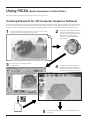
Creating Elements for 3D Computer Graphics Software
Dr. PICZA offers a function for exporting files in three-dimensional DXF format (AutoCAD® Release 12 format). This section explains
how to use a commercially available 3D computer-graphics software application that can import DXF-format files to create your own
original illustrations. (This product does not include 3D computer-graphics software, which must be obtained from another source.)
1
Visualize in detail the design illustration you wish to create. In this
example, we'll make the illustration shown below.
3
Scan the clay face and export the data
in DXF format.
DXF-format file
6
5
2
Create the elements that make up the
illustration. In this example, we'll use
the clay included with the product to
make the face, and the graphics
software to make the other element
(the pyramid).
4
Launch the 3D graphics application
and import the DXF file. Make the
pyramid and arrange the face and the
pyramid using the layout shown below.
Use the 3D graphics software to color the illustration, then
print it out.
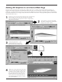
Adding 3D Graphics to an Internet Web Page
Dr. PICZA comes with a function for exporting files in VRML format (Ver.1.0). VRML (Virtual Reality Modeling Language) is a
language used to display 3D graphics on the World Wide Web, where they can be viewed using a web browser capable of displaying
VRML files. Color data from Dr. PICZA is also preserved in these VRML files. In this example, we'll add the image of a original fishing
lure scanned with the PIX-3 to a web page. (This product does not include a web browser or web-page authoring software, which must be
obtained from another source.)
1
Set the lure in place on the workpiece table and scan it with the PIX-3.
In this example, we'll scan only one side of the lure, and use Dr.
PICZA's [Add Backside Faces] function to make a complete threedimensional representation.
2
3
Use Dr. PICZA to color the scanned data.
(For details on adding color, please refer to
the help screens for Dr. PICZA.)
Under [File]-[Preferences...], click
[Add Backside Faces] to turn it on,
then export the data in VRML format.
VRML-format file
4
VRML files can be opened and viewed with a
web browser that supports the VRML format.
By adding a link to a VRML file from a web
page, you can also display the VRML file on
the World Wide Web. (For details on how to
do this, please refer to the documentation for
your web-page authoring software or a thirdparty guide to HTML.)
7
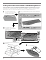
Cutting a Three-dimensional Object with a Modeling Machine
Dr. PICZA has a function for exporting data to MODELA PLAYER. MODELA PLAYER is software for cutting three-dimensional
objects on the MODELA, CAMM-3, or CAMM-2, three-dimensional modeling machines made by Roland DG Corp. Dr. PICZA can
output 3D data directly to MODELA PLAYER. In this example, we'll use the MODELA in combination with Dr. PICZA to make a
paperweight in the shape of a leaf. The explanation assumes that you already have the MODELA installed and set up.
1
Get a suitable leaf from a tree, and
press it into a piece of clay to transfer
the image of the leaf to the clay.
3
Use [Edit]-[Invert] to invert the
scanned shape, then export the data to
MODELA PLAYER.
2
Set the piece of clay on the workpiece table and scan it with the PIX-3.
Before inversion
After inversion
Export to
MODELA
PLAYER
4
Use MODELA PLAYER to cut the shape on the
MODELA.
5
8
Color the cut object.
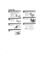
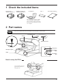
1 Check the included items
Dr. PICZA for
Windows® 95 disks: 2
MODELA PLAYER for
Windows® 95 disks: 2
AC adapter: 1
Clay: 1
PIX-3 User's manual
:1
The configuration of the AC adapter
varies according to regional differences in voltage. Please note that the
descriptions in this manual are for the
117 V adapter.
2 Part names
Except when repacking the unit, do not attempt to move the table or Z unit by hand.
AC adapter jack
Z unit
Serial connector
Sensor
VIEW LED
Workpiece plate
STANDBY
LED
Table
STANDBY
key
How to carry the PIX-3
Use two hands to securely
grip this area on the left
and right sides.
9
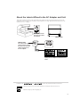
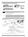
3 Setting up and connection
Do not use with any electrical power
supply that does not meet the
ratings displayed on the AC adapter.
Install on a stable surface.
Failure to do so
may result in
falling of the unit,
leading to injury.
Use with any other power supply may lead
to fire or electrocution.
Do not use with any power supply
other than the dedicated AC adapter.
Use with any other power supply may lead
to fire or electrocution.
Never install this unit in any of the following situations, as it could result in damage:
Places where the installation surface is unstable or not level.
Places with excessive electrical noise.
Places with excessive humidity or dust.
Places with poor ventilation, because the PIX-3 generates considerable heat during operation.
Places with excessive vibration.
Use within a temperature range of 5 to 40°C (41 to 104°F) and within a humidity range of 35 to 80%.
Securely connect the power cord, computer I/O cable and so on so that they will not be unplugged and cause
failure during operation. Doing so may lead to faulty operation or breakdown.
The AC adapter plugs in here
Connect the unit to the computer
Serial connector
AC adapter jack
AC adapter
When connected to the AC
adapter, the STANDBY LED
and VIEW LED flash in
alternation, then go dark.
Serial connector
Use a commercially
available Phillips
screwdriver to tighten the
screws at either end of
the serial cable.
Serial cable
Use a crossing serial cable (RS-232C) to
connect the computer and the PIX-3.
A straight serial cable such as is commonly
used to connect a modem cannot be used.
Leave about 10 cm (4") of open space
behind the unit.
* Do not place objects near the AC
adapter jack or serial connector.
• The cable is available separately. Be sure to use the correct cable for the computer.
• Make sure the power to the computer and the PIX-3 is switched off before attempting to connect the cables.
10
4 Installing the Dr. PICZA and the MODELA PLAYER
Symbols used in the section on software
The explanations in this section may abbreviate the names of the included
software as follows
Dr. PICZA for Windows® 95 = Dr. PICZA
MODELA PLAYER for Windows® 95 = MODELA PLAYER
The symbols used in this section are as follows.
Dr. PICZA and MODELA PLAYER are
software that run under Windows 95. The
explanations in this manual assume that you
are already familiar with the basic operation of
Windows 95.
= An on-screen area to be clicked.
Overview of Dr. PICZA
* For details, please refer to the help screens for Dr. PICZA.
A Quick Overview of Available Functions
Toolbar button
Set scanning conditions and perform scanning
View scanned 3D data from various angles
Zoom in or out on the on-screen view of scanned data
Make settings for how scanned 3D data is displayed
Color the faces of scanned 3D data
Edit scanned 3D data
Adjust the slant of scanned 3D data
Specify the data format and save the scanned 3D data
Launch the MODELA PLAYER
Overview of MODELA PLAYER
MODELA PLAYER is software for performing 3D modeling on the MODELA, CAMM-3, or CAMM-2 three-dimensional modeling
machines from Roland DG Corp. Dr. PICZA can output 3D data directly to MODELA PLAYER. You should install MODELA PLAYER
only if you will be using a three-dimensional modeling machine from Roland DG Corp. to machine data scanned with Dr. PICZA. For
more information, please refer to the help screens for MODELA PLAYER.
11
Installing
Hard disk
:C
Floppy-disk drive : A
* If your drive-name assignments differ from the ones
shown at left, make the appropriate changes.
1
Switch on the computer and start Windows 95.
2
Dr. PICZA: Insert the Dr. PICZA disk 1/2 included with the unit.
MODELA PLAYER: Insert the MODELA PLAYER disk 1/2 included with the unit.
3
Double-click on the [My Computer] icon on screen.
5
Double-click on the [setup.exe] icon.
4
Double-click on the [3-1/2 Floppy] icon.
This starts the setup program. Follow the messages to carry out setup.
For MODELA PLAYER, at the screen for selecting the machine,
make the setting for the Roland DG Corp.'s modeling machine you're
using.
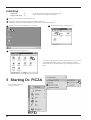
5 Starting Dr. PICZA
Press the Start button and
select [Dr. PICZA].
12
About Help
If you're unsure how perform an operation while you're working, taking a look at Help
can find the answer. If you're using Dr. PICZA for the first time, please be sure to read
the Help screens. You can call up Help from the software menus.
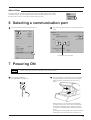
6 Selecting a communication port
1
Press the File button and select [Preferences...].
2
Select the port where the cable is connected, then click
[OK].
Click either one or the other
7 Powering ON
Before switching on the power to the PIX-3, turn on the computer.
1
Press the STANDBY key.
The STANDBY LED lights up.
2
The unit performs its initialization routine, then stops.
(During initialization, the sound of the moving table
and Z unit may be somewhat loud. This is not a
defect.)
When the unit is in its initialized state immediately
switching on the power, an error may be displayed if
some object touches the sensor. (When an error has
occurred, the STANDBY LED intermittently flashes
twice.)
If this happens, switch off the power, remove the object
touching the sensor, then switch the power back on.
13
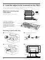
8 Load the object to be scanned on the PIX-3
The sensors for the PIX-3 are highly sensitive, and can even scan three-dimensional objects made out of clay.
Any solid object made of material that can hold its shape can be scanned.
Maximum scanning area
of the PIX-3
Maximum
scanning area
The maximum scanning area is shown in the figure.
In this section, we'll prepare a
three-dimensional object made out
of clay, then carry out the steps
from securing the object to the
workpiece plate to saving the data.
The explanation in this section is
for a fish made with the clay that is
included.
Workpiece plate
X: 75 mm (2-15/16")
Y: 30 mm (1-3/16")
Z: 5 mm (0.2")
Securing in place with clay
1
Loosen the plate mounting screws.
2
Slide the workpiece plate toward the rear.
Mounting screw
Hole in the
workpiece plate
3
Remove the workpiece plate.
4
Use clay to fashion a base on the workpiece plate.
Workpiece plate
14
Clay
10 mm (0.39")
5
Press the scan object into the clay to hold it in place.
Make sure the scan object is held securely so that it
does not move during scanning.
The PIX-3 can scan objects with a height of
up to 10 mm (7/16") from the top surface of
the workpiece plate. If the height is insufficient, make the base higher.
The mounting method is described in detail in
the help files for Dr. PICZA. Please refer to
the Dr. PICZA help screens.
Scan object
Workpiece plate
Clay
6
Mount the workpiece plate on the PIX-3.
Slide the workpiece plate toward the front, as shown in
the figure.
7
Tighten the plate mounting screws securely.
Mounting screw
Hole in the workpiece plate
Make sure the back and
front of the workpiece
plate are set up correctly.
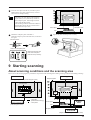
9 Starting scanning
About scanning conditions and the scanning area
Please refer to the following figures to perform the steps for the tasks extending from "Setting scanning conditions and starting scanning".
Y SCAN PITCH
Scanning Area
(Spacing of adjacent scan points along the Y axis)
Workpiece plate
Scanning area
UR
LL
X SCAN PITCH
(Spacing of adjacent scan
points along the X axis)
: Scan path
(bidirectional scanning)
: Scan points
Z Upper
Limit
Scan object
Clay
Workpiece plate
Z BOTTOM
(Height of the scanning area's bottom plane)
15
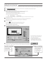
Setting scanning conditions and starting scanning
Do not place hands near the z unit
while in operation.
Doing so may
result in injury.
Doing so may
lead to faulty
operation or
breakdown.
Make the settings for scanning resolution, the minimum height of the surface to be scanned, and the scanning quality.
1
Click
on the Dr. PICZA.
The Remote Controller window opens.
When Dr. PICZA is started, the Remote Controller window is already open.
2
Make the settings for X scan pitch and Y scan pitch.
The setting in this example is for 0.50 mm (0.020").
3
Make the setting for Z bottom.
The setting in this example is for 10 mm (0.394").
4
Make the selection for scanning quality.
Here, click [Fine] to activate this setting.
5
Here, click [Smart Scan] to activate the setting.
When the [Smart Scan] setting is on, clicking [Scan] makes the PIX-3
automatically restrict the scanning area (on the X-Y plane only) before
scanning is performed.
To specify the scanning area, turn off [Smart Scan] and refer to "Setting the
scanning area" to make the desired settings.
2
2
3
4
5
6
6
Click
.
Scanning starts.
(During scanning, the sensor may
emit a transmission sound, but this is
normal.)
For detailed description of the available
Remote Controller buttons, please refer to
the help screens for Dr. PICZA.
16
Setting the scanning area
If you wish to limit the scanning area, such as in cases where you wish to scan only a portion of an object, make the settings as described
below.
1
Click
2
Make the settings for the scanning area.
Make the settings to match the location where the scan object is secured in place.
Either of the following two methods can be used to make the settings.
- Use the mouse to move the blue frame on screen.
- Enter the numerical values for the upper-right and lower-left points.
in the Remote Controller window. The [Scanning Area] dialog box appears.
In this case, enter the following information.
UR: X 107.5 (4.232")
Y 62.50 (2.461")
LL:
X 27.50 (1.083")
Y 27.50 (1.083")
The size of the on-screen scanning area (shown in blue) changes to match the values that are entered.
3
Click [Begin Area Test].
The sensor moves to a position above an outer point on the scanning area that has been set.
Make sure the scan object that has been secured in place lies within the area.
4
Click [Z Upper Limit].
The cursor
is displayed on the Z upper-limit setting on screen.
Specify the highest position of the scan object and click [Apply].
If the target is displaced, redo the settings.
5
After determining the scanning area, click [OK].
5
4
• For the scanning area and Z upper limit,
please refer to "About scanning conditions and the scanning area".
2
4
3
6
4
• For details about the buttons on the
scanning-region setting screen, please
refer to the help screens for Dr. PICZA.
Check the scanning conditions in the Remote Controller window one more time, then click
.
Scanning starts. (During scanning, the sensor may emit a transmission sound, but this is normal.)
Cancels scanning
Cancels scanning.
Any data scanned
before being canceled
remains in memory.
Pauses scanning
Pauses scanning and
moves the sensor to
the VIEW position.
Click [VIEW] again to
resume scanning.
17
10 Saving scanned data
1
-
Click
.
The [Save As] dialog box appears.
2
Choose the desired location for saving the file, enter a file name, and click [SAVE].
The extension ".pix" is appended to the file name.
If you want to export the data as a file in DXF or VRML format, please refer to the help screens for Dr. PICZA.
Edit the scanned data
The shape of an object can be edited. It is possible to vary the height, adjust the slant, or perform concave/convex inversion (height
inversion) for a desired surface.
You can use the toolbar button or select [Edit] on the menu bar.
Please refer to the help screens for Dr. PICZA for detailed explanations of the various functions that are available.
Be sure to save the scanned data before starting to edit.
When you're done editing, be sure to save your file.
Cutting scan data with the modeling machine to make a 3D object
1
Click
-
.
In the [Open] dialog box, open the file containing the scan data to be cut.
2
MODELA PLAYER screen
Click
.
MODELA PLAYER starts, and the 3D
data in the file you opened in step 1
appears on screen.
3
18
Load the material and install the blade on
the modeling machine. For more
information, refer to the manual for your
modeling machine.
4
Make the settings for the cutting
conditions. Clicking [NEXT]
advances the setting screens in
sequence from A to D. Make the
settings in order from A to D.
(Clicking A, B, C, or D in the
figure displays the corresponding
setting screen, this should not be
used except when it's necessary
to make settings independently.)
A
B
C
D
Click here to advance to
the next settings.
A Select the direc-
This displays the path of
the tool during cutting.
B Set the dimension
Select the direction to be used
for cutting the object.
In the figure at right, cutting
from above is selected.
Make the setting for object's
size.
Drag the spin dial up or down,
or click on a number and enter a
value from the keyboard.
Clicking [Resize] makes it
possible to specify a ratio for the
dimensions.
C Set the maximum
D
tion of the object
cutting depth
Make the setting for the
maximum cutting depth.
Drag the spin dial up or down,
or click on a number and enter a
value from the keyboard.
Clicking [Center] sets the depth
at a location proportional to the
height.
Tool diameter
Set the type and diameter of the
tool that is installed.
Material
Choose the composition of the
loaded material.
Finish
When cutting a solid object on a
modeling machine, an attractive
finish can be obtained by first
performing rough (draft) cutting,
then performing fine cutting. Set
to [Draft] for the first pass, and
to [Fine] for the second pass.
19
5
On the menu bar, click [File], then click [SAVE]. The [Save As] dialog box opens.
6
Choose the location for saving the file, enter a name for the file, then click [SAVE]. The extension [.mdj] is appended to the
filename.
7
Click [START] to start cutting.
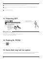
11 Powering OFF
Press the STANDBY key.
The STANDBY LED goes out.
When not in use for extended
periods, unplug the AC adapter from
the electrical outlet.
Failure to do so
may result in
danger of shock,
electrocution, or fire
due to deterioration
of the electrical
insulation.
When not in use
- Remove the scan object from the table.
- Remove any clay from table, and store the clay so that it will not dry out.
- Unplug the AC adapter from the electrical outlet.
12 Ending Dr. PICZA
Crick the
button.
13 Items that may not be copied
Unauthorized reproduction of a copyrighted item for any purpose other than personal use may be a violation of copyright. Roland DG
Corp. will not be responsible for any violation of third-party copyright by any article made through use of this product.
20
14 What to do if...
If you want to completely stop the operation of the PIX-3, detach the AC adapter from AC outlet.
The PIX-3 doesn't operate
Check the following.
- Is the STANDBY key on (with the STANDBY LED lit
up)?
- Are the settings for the computer and software correct?
- Are the cable connected correctly?
Pressing the STANDBY key does not switch off the
power.
Unplug the AC adapter from the unit.
The STANDBY LEDs repeatedly flashes once
This may indicate a hardware error. Try switching the power
off and back on, then repeating the desired operation. If the
same error display occurs, consult your authorized Roland
dealer or service center.
The STANDBY LEDs repeatedly flashes three
times
This indicates a communications error.
Switch off the power and check the following.
- Are the communications port settings made for Dr.
PICZA correct?
- Are the connections for the AC adapter and the cable
connecting the unit to the computer secure?
- Are the AC adapter and the cable connecting the unit to
the computer free of any internal broken wires?
- Is the operation of the computer correct?
- Was the power to the computer switched on before the
PIX-3 was turned on? (Be sure to power up the computer first, then switch on the power to the PIX-3.)
The tip of the sensor was inadvertently bent
Please purchase a sensor unit APS-1 (sold separately).
The STANDBY LEDs repeatedly flashes twice
- When the unit is in its initialized state immediately
switching on the power, the error may be displayed if some
object touches the sensor.
If this happens, switch off the power, remove the object
touching the sensor, then switch the power back on.
- This may indicate a hardware error. Try switching the
power off and back on, then repeating the desired operation. If the same error display occurs, consult your
authorized Roland dealer or service center.
21
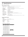
15 Specifications
Main unit specifications
Max. scanning area
: 152.4 mm (X) x 101.6 mm (Y) x 40.65 mm (Z) (6" (X) x 4" (Y) x 1-9/16" (Z))
Max. scan-object weight : 400 g (0.9 lb.)
Sensor
: Roland Active Piezo Sensor (R.A.P.S.)
Probe length 40 mm (1-9/16"), tip bulb diameter 0.08 mm (0.00315")
Scanning method
: Contacting, mesh-point height-sensing
Scanning pitch
: X/Y-axis directions -- 0.05 to 5.00 mm (0.002" to 0.20") (settable in steps of 0.05 mm (0.002"))
(Dr. PICZA)
Z-axis direction -- 0.025 mm (0.000984")
Scanning speed
: 4—15 mm/sec. (1/8"/sec.—9/16"/sec.)
Exportable file formats : DXF and VRML
Interface
: Serial (RS-232C)
Control keys
: STANDBY key
LED
: STANDBY LED, VIEW LED
Power consumption
: Exclusive AC adapter (DC+12V 1.5 A)
Acoustic noise level
: Standby mode: under 24 dB (A)
Scanning mode: under 40 dB (A)
(According to ISO 7779)
External dimensions
: 350 mm (W) x 380 mm (D) x 310 mm (H) (13-13/16" (W) x 15" (D)) x 12-1/4" (H))
Weight (unit only)
: 8 kg (17.6 lb.)
Operation temperature : 5—40°C (41—104°F)
Operation humidity
: 35—80 % (no condensation)
Accessories
: Dr. PICZA for Windows® 95 disks: 2, MODELA PLAYER for Windows® 95 disks: 2, AC adapter: 1,
clay: 1, PIX-3 user's manual: 1
Interface Specification
[Serial]
Standard
Transmission method
Transmission speed
Parity Check
Data Bits
Stop Bits
Handshake
:
:
:
:
:
:
:
RS-232C specifications
Asynchronous, duplex data transmission
9600 bps
None
8 bits (fixed)
1 bits (fixed)
Hardwire
Serial connector (RS-232C)
Signal
Terminal
number number
22
Signal
number
NC
25
13
NC
NC
24
12
NC
NC
23
11
NC
NC
22
10
NC
NC
21
9
NC
DTR
20
8
NC
NC
19
7
SG
NC
18
6
DSR
NC
17
5
CTS
NC
16
4
RTS
NC
15
3
RXD
NC
14
2
TXD
1
FG
Pin connection
13
1
25
14
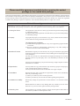
Please read this agreement carefully before opening the sealed
package or the sealed disk package
Opening the sealed package or sealed disk package implies your acceptance of the terms and conditions of this agreement.
If you do NOT accept this agreement, retain the package UNOPENED. (This product is just one of included items. Please
be aware that any amount of the purchase price will not be refunded for return of this product as a single item, regardless
of whether the package is opened or unopened.) The enclosed Roland product is a single user version.
Roland License Agreement
Roland DG Corporation ("Roland") grants you a non-assignable and non-exclusive right to use the COMPUTER
PROGRAMS in this package ("Software") under this agreement with the following terms and conditions.
1. Coming into Force
This agreement comes into force when you purchase and open the sealed package
or sealed disk package.
The effective date of this agreement is the date when you open the sealed package
or sealed disk package.
2. Property
Copyright and property of this Software, logo, name, manual and all literature
for this Software belong to Roland and its licenser.
The followings are prohibited :
(1) Unauthorized copying the Software or any of its support file, program module
or literature.
(2) Reverse engineering, disassembling, decompiling or any other attempt to
discover the source code of the Software.
3. Bounds of License
Roland does not grant you to sub-license, rent, assign or transfer the right granted
under this agreement nor the Software itself (including the accompanying items)
to any third party.
You may not provide use of the Software through time-sharing service and/or
network system to any third party who is not individually licensed to use this
Software.
You may use the Software by one person with using a single computer in which
the Software is installed.
4. Reproduction
You may make one copy of the Software only for back-up purpose. The property
of the copied Software belongs to Roland.
You may install the Software into the hard disk of a single computer.
5. Cancellation
Roland retains the right to terminate this agreement without notice immediately
when any of followings occurs :
(1) When you violate any article of this agreement.
(2) When you make any serious breach of faith regarding this agreement.
6. Limitations on Liability
Roland may change the specifications of this Software or its material without
notice.
Roland shall not be liable for any damage that may caused by the use of the
Software or by exercise of the right licensed by this agreement.
7. Governing Law
This agreement is governed by the laws of Japan, and the parties shall submit to
the exclusive jurisdiction of the Japanese Court.
R4-980213