1
USER'S MANUAL
Thank you very much for purchasing the PIX-30.
•
To ensure correct and safe usage with a full understanding of
this product's performance, please be sure to read through this
manual completely and store it in a safe location.
•
Unauthorized copying or transferral, in whole or in part, of
this manual is prohibited.
•
The contents of this operation manual and the specifications of
this product are subject to change without notice.
•
The operation manual and the product have been prepared and
tested as much as possible. If you find any misprint or error,
please inform us.
For the USA
FEDERAL COMMUNICATIONS COMMISSION
RADIO FREQUENCY INTERFERENCE
STATEMENT
This equipment has been tested and found to comply with the
limits for a Class A digital device, pursuant to Part 15 of the
FCC Rules.
These limits are designed to provide reasonable protection
against harmful interference when the equipment is operated
in a commercial environment.
This equipment generates, uses, and can radiate radio
frequency energy and, if not installed and used in accordance
with the instruction manual, may cause harmful interference
to radio communications.
Operation of this equipment in a residential area is likely to
cause harmful interference in which case the user will be
required to correct the interference at his own expense.
Unauthorized changes or modification to this system can void
the users authority to operate this equipment.
The I/O cables between this equipment and the computing
device must be shielded.
For Canada
CLASS A
NOTICE
This Class A digital apparatus meets all requirements of the
Canadian Interference-Causing Equipment Regulations.
CLASSE A
AVIS
Cet appareil numérique de la classe A respecte toutes les
exigences du Règlement sur le matériel brouilleur du
Canada.
ROLAND DG CORPORATION
1-6-4 Shinmiyakoda, Hamamatsu-shi, Shizuoka-ken, JAPAN 431-2103
MODEL NAME
: See the MODEL given on the rating plate.
RELEVANT DIRECTIVE : EC MACHINERY DIRECTIVE (98/37/EC)
EC LOW VOLTAGE DIRECTIVE (73/23/EEC)
EC ELECTROMAGNETIC COMPATIBILITY DIRECTIVE (89/336/EEC)
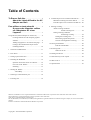
Table of Contents
To Ensure Safe Use .......................................... 2
About the Labels Affixed to the AC
Adapter and Unit ..................................... 4
8 Load the object to be scanned on the PIX-30 ........ 19
Maximum scanning area of the PIX-30 ........... 19
Load the object to be scanned on the PIX-30 .. 20
Pour utiliser en toute sécurité ................... 5
À propos des étiquettes collées
sur l’adaptateur AC et sur
l’appareil ....................................................... 7
9 Starting scanning .................................................... 24
About scanning conditions
and the scanning area ................... 24
Setting scanning conditions
and starting scanning .................... 24
Setting the scanning area ............................ 26
Rescanning a particular portion .................. 27
Cancels scanning/Pauses scanning ............. 27
Using PICZA (Some Examples of Actual Use) ............ 8
Creating elements for 3D computer graphics
software .............................................................. 8
Adding 3D graphics to an internet web page ..... 9
Cutting a three-dimensional object with a
modeling machine ............................................ 10
10 Saving scanned data .............................................. 28
Edit the scanned data .................................. 28
1 Check the included items ....................................... 11
11 Powering OFF ........................................................ 28
When not in use .......................................... 28
2 Part names .............................................................. 11
12 Ending Dr. PICZA ................................................. 29
3 Setting up and connection ...................................... 12
13 Items that may not be copied ................................. 29
4 Installing the Dr.PICZA ......................................... 14
Symbols used in the section on software ......... 14
Overview of Dr. PICZA ................................... 14
Installing ........................................................... 15
14 What to do if... ....................................................... 29
15 Specifications ........................................................ 30
5 Starting Dr. PICZA ................................................ 17
About Help ................................................. 17
6 Selecting a communication port ............................ 18
7 Powering ON ......................................................... 19
Windows® and Windows NT® are registered trademarks or trademarks of Microsoft® Corporation in the United States and/or other countries.
i486 and Pentium are registered trademarks of Intel Corporation in the United States.
AutoCAD® is registered trademark of Autodesk, Inc.
Mac OS, Macintosh, Power Macintosh, PowerBook, and AppleTalk are registered trademarks or trademarks of Apple Computer, Inc. in the USA and other
countries.
PowerPC is trademark of International Business Machines Corporation.
Copyright © 1999 Roland DG Corporation
1
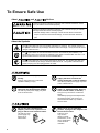
To Ensure Safe Use
About
and
Notices
Used for instructions intended to alert the user to the risk of death or severe
injury should the unit be used improperly.
Used for instructions intended to alert the user to the risk of injury or material
damage should the unit be used improperly.
* Material damage refers to damage or other adverse effects caused with
respect to the home and all its furnishings, as well to domestic animals or
pets.
About the Symbols
The
symbol alerts the user to important instructions or warnings. The specific meaning of
the symbol is determined by the design contained within the triangle. The symbol at left means
"danger of electrocution."
The
symbol alerts the user to items that must never be carried out (are forbidden). The
specific thing that must not be done is indicated by the design contained within the circle. The
symbol at left means the unit must never be disassembled.
The
symbol alerts the user to things that must be carried out. The specific thing that must
be done is indicated by the design contained within the circle. The symbol at left means the
power-cord plug must be unplugged from the outlet.
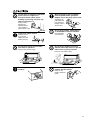
Do not disassemble, repair, or
modify.
Doing so may lead to fire or abnormal
operation resulting in injury.
Do not use with any power supply
other than the dedicated AC adapter.
Use with any other power supply may lead
to fire or electrocution.
2
Do not use with any electrical power
supply that does not meet the
ratings displayed on the AC adapter.
Use with any other power supply may lead
to fire or electrocution.
Do not use while in an abnormal
state (i.e., emitting smoke, burning
odor, unusual noise, or the like).
Doing so may result in fire or electrical
shock.
Immediately unplug the AC adapter from
the electrical outlet, and contact your
authorized Roland DG Corp. dealer or
service center.
Do not use with a damaged AC
adapter, power cord, or power-cord
plug or with a loose electrical outlet.
When not in use for extended
periods, unplug the AC adapter from
the electrical outlet.
Use with any other
power supply may
lead to fire or
electrocution.
Failure to do so
may result in
danger of shock,
electrocution, or fire
due to deterioration
of the electrical
insulation.
Do not injure or modify the electrical
power cord, nor subject it to
excessive bends, twists, pulls,
binding, or pinching, nor place any
object of weight on it.
Doing so may
damage the
electrical power
cord, leading to
electrocution or fire.
Install on a stable surface.
Failure to do so
may result in
falling of the unit,
leading to injury.
Do not place hands near the main
unit while in operation.
Doing so may result in injury.
When unplugging the AC adapter
from the power outlet, grasp the
adapter unit or the plug, not the cord.
Unplugging by
pulling the cord
may damage it,
leading to fire or
electrocution.
Do not allow liquids, metal objects
or flammables inside the machine.
Such materials
can cause fire.
Do not allow children to operate
without adult supervision or operate
within reach of young children.
Doing so may result in injury.
Store clay out of the reach of
children.
Do not attempt to unplug the AC
adapter with wet hands.
Doing so may
result in electrical
shock.
3
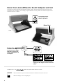
About the Labels Affixed to the AC Adapter and Unit
These labels are affixed to the body of this product and the AC adapter. The following figure describes the location. The
configuration of the AC adapter varies according to regional differences in voltage. Please note that the descriptions in this
manual are for the 117 V adapter.
Do not place hands
near the main unit
while in operation.
Model label
Front
Rear
Rating label
Do not use with any
electrical power supply
that does not meet the
ratings displayed on the
AC adapter.
When not in use for prolonged periods,
unplug the AC adapter from the electrical
outlet.
In addition to the
NOTICE
and
symbols, the symbols shown below are also used.
: Indicates information to prevent machine breakdown or malfunction and ensure correct use.
: Indicates a handy tip or advice regarding use.
4
Pour utiliser en toute sécurité
Avis sur les avertissements
Utilisé pour avertir l'utilisateur d'un risque de décès ou de blessure grave en
cas de mauvaise utilisation de l'appareil.
Utilisé pour avertir l'utilisateur d'un risque de blessure ou de dommage
matériel en cas de mauvaise utilisation de l'appareil.
* Par dommage matériel, il est entendu dommage ou tout autre effet
indésirable sur la maison, tous les meubles et même les animaux
domestiques.
À propos des symboles
Le symbole
attire l'attention de l'utilisateur sur les instructions importantes ou les
avertissements. Le sens précis du symbole est déterminé par le dessin à l'intérieur du triangle.
Le symbole à gauche signifie "danger d'électrocution".
Le symbole
avertit l'utilisateur de ce qu'il ne doit pas faire, ce qui est interdit. La chose
spécifique à ne pas faire est indiquée par le dessin à l'intérieur du cercle. Le symbole à
gauche signifie que l'appareil ne doit jamais être démonté.
Le symbole
prévient l'utilisateur sur ce qu'il doit faire. La chose spécifique à faire est
indiquée par le dessin à l'intérieur du cercle. Le symbole à gauche signifie que le fil électrique
doit être débranché de la prise.
Ne pas démonter, réparer ou
modifier.
Le non-respect de cette consigne pourrait
causer un incendie ou provoquer des
opérations anormales entraînant des
blessures.
Ne pas utiliser avec une alimentation
électrique autre que l’adaptateur AC
conçu à cet effet.
Une utilisation avec toute autre alimentation
électrique pourrait provoquer un incendie
ou une électrocution.
Ne pas utiliser avec une alimentation
électrique ne respectant pas les
caractéristiques indiquées sur
l’adaptateur AC.
Une utilisation avec toute autre alimentation
électrique pourrait provoquer un incendie
ou une électrocution.
Ne pas utiliser si l'appareil est dans
un état anormal (c'est-à-dire s'il y a
émission de fumée, odeur de brûlé,
bruit inhabituel etc.).
Le non-respect de cette consigne pourrait
provoquer un incendie ou des décharges
électriques.
Débrancher immédiatement l’adaptateur AC
et contacter votre agent agréé de la
compagnie Roland DG ou votre centre de
service.
5
Ne pas utiliser avec un adaptateur
AC ou un fil électrique endommagé
ou avec une prise électrique qui a du
jeu.
Une utilisation avec
toute autre alimentation
électrique pourrait
provoquer un incendie
ou une électrocution.
Ne pas endommager ou modifier le
fil électrique. Ne pas le plier, le
tordre, l'étirer, l'attacher ou le serrer
de façon excessive. Ne pas mettre
d'objet ou de poids dessus.
Une négligence à
ce niveau pourrait
endommager le fil
électrique ce qui
risquerait de
provoquer une
électrocution ou un
incendie.
Installer l’appareil sur une surface
stable.
Une négligence à
ce niveau pourrait
provoquer la chute
de l’appareil et
entraîner des
blessures.
Ne pas placer vos mains près de
l’unité principale pendant son
fonctionnement.
Le non respect de cette consigne pourrait
causer des blessures.
Quand l’appareil reste inutilisé
pendant plusieurs heures,
débrancher l’adaptateur AC.
Le non respect de cette
consigne pourrait
causer des risques de
décharges électriques,
d’électrocution, ou
d’incendie dus à la
détérioration de
l’isolation électrique.
Lorsque vous débranchez
l’adaptateur AC, saisir et tirer le bloc
adaptateur et non le fil électrique.
Débrancher en tirant sur le fil pourrait
l'endommager et risquer de provoquer un
incendie ou une électrocution.
Ne pas introduire de liquide, d'objet
métallique ou inflammable dans
l'appareil.
Ce genre de
matériel peut
provoquer un
incendie.
Ne pas laisser des enfants faire
fonctionner l’appareil sans la
surveillance d’un adulte ni laisser
l’appareil en fonctionnement à la
portée d’enfants en bas âge.
Une négligence à ce niveau pourrait
provoquer des blessures.
Ranger la pâte hors de la portée des
enfants.
Ne pas débrancher l’adaptateur AC
avec des mains mouillées.
Une négligence à
ce niveau pourrait
provoquer des
décharges
électriques.
6
À propos des étiquettes collées sur l’adaptateur AC
et sur l’appareil
Ces étiquettes sont collées sur le corps de l’appareil et sur l’adaptateur AC. Le dessin suivant indique leur emplacement. La
configuration de l’adaptateur AC varie selon les différences de voltage régionales. Veuillez noter que les descriptions dans ce
manuel correspondent à un adaptateur de 117 volts.
Ne pas placer vos
mains près de
l’unité principale
pendant son
fonctionnement.
Nom du modèle
Avant
Arrière
Étiquette des
caractéristiques électriques
Ne pas utiliser avec une
alimentation électrique ne
respectant pas les
caractéristiques indiquées sur
l’adaptateur.
Quand l’appareil reste inutilisé pendant
une longue période, débrancher
l’adaptateur AC.
7
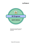
Using PICZA (Some Examples of Actual Use)
This section presents some actual examples of how PICZA can be put to use.
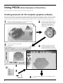
Creating elements for 3D computer graphics software
Dr. PICZA offers a function for exporting files in three-dimensional DXF format (AutoCAD® Release 12 format). This section explains
how to use a commercially available 3D computer-graphics software application that can import DXF-format files to create your own
original illustrations. (This product does not include 3D computer-graphics software, which must be obtained from another source.)
1
Visualize in detail the design illustration you wish to create. In this
example, we'll make the illustration shown below.
3
Scan the clay face and export the data
in DXF format.
DXF-format file
8
5
2
Create the elements that make up the
illustration. In this example, we'll use
the clay included with the product to
make the face, and the graphics
software to make the other element
(the pyramid).
4
Launch the 3D graphics application
and import the DXF file. Make the
pyramid and arrange the face and the
pyramid using the layout shown below.
Use the 3D graphics software to color the illustration, then
print it out.
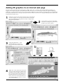
Adding 3D graphics to an internet web page
Dr. PICZA comes with a function for exporting files in VRML format (Ver.1.0). VRML (Virtual Reality Modeling Language) is a
language used to display 3D graphics on the World Wide Web, where they can be viewed using a web browser capable of displaying
VRML files. Color data from Dr. PICZA is also preserved in these VRML files. In this example, we'll add the image of a original fishing
lure scanned with the PIX-30 to a web page. (This product does not include a web browser or web-page authoring software, which must
be obtained from another source.)
1
Set the lure in place on the workpiece table and scan it with the PIX30. In this example, we'll scan only one side of the lure, and use Dr.
PICZA's [Add Backside Faces] function to make a complete threedimensional representation.
2
3
Use Dr. PICZA to color the scanned data.
(For details on adding color, please refer to
the help screens for Dr. PICZA.)
Under [File]-[Preferences...], click
[Add Backside Faces] to turn it on,
then export the data in VRML format.
VRML-format file
4
VRML files can be opened and viewed with a
web browser that supports the VRML format.
By adding a link to a VRML file from a web
page, you can also display the VRML file on
the World Wide Web. (For details on how to
do this, please refer to the documentation for
your web-page authoring software or a thirdparty guide to HTML.)
9
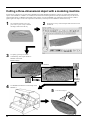
Cutting a three-dimensional object with a modeling machine
Dr. PICZA has a function for exporting data to MODELA PLAYER. MODELA PLAYER is software for cutting three-dimensional
objects on the MODELA, CAMM-3, or CAMM-2, three-dimensional modeling machines made by Roland DG Corp. Dr. PICZA can
output 3D data directly to MODELA PLAYER. In this example, we'll use the MODELA in combination with Dr. PICZA to make a
paperweight in the shape of a leaf. The explanation assumes that you already have the MODELA installed and set up.
1
Get a suitable leaf from a tree, and
press it into a piece of clay to transfer
the image of the leaf to the clay.
3
Use [Edit] - [Invert] to invert the
scanned shape, then export the data to
MODELA PLAYER.
2
Set the piece of clay on the workpiece table and scan it with
the PIX-30.
Before inversion
After inversion
Export to
MODELA
PLAYER
4
Use MODELA PLAYER to cut the shape on the
MODELA.
5
10
Color the cut object.
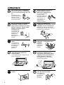
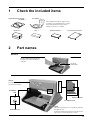
1
Check the included items
Roland Software Package
CD-ROM: 1
AC adapter: 1
The configuration of the AC adapter varies
according to regional differences in voltage.
Please note that the descriptions in this
manual are for the 117 V adapter.
Spacers: 2
2
Clay: 1
Adhesive sheets: 2
PIX-30 User's manual: 1
Part names
NOTICE
Do not attempt to move the table by hand.
Do not put the hands inside the unit.
Doing so may result in breakdown
of the unit.
Do not put
hands inside.
Sensor
This remains inside the cover
except during scanning.
STANDBY
LED
Serial connector
AC adapter jack
Table
STANDBY key
The grid on the table serves as a guide for mounting
the object to scan.
It does not indicate the scanning area for Dr. PICZA.
The scale is in 10 mm (about 3/8 in.) units.
11
3
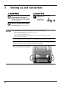
Setting up and connection
Do not use with any electrical power
supply that does not meet the
ratings displayed on the AC adapter.
Use with any other power supply may lead
to fire or electrocution.
Install on a stable surface.
Failure to do so
may result in
falling of the unit,
leading to injury.
Do not use with any power supply
other than the dedicated AC adapter.
Use with any other power supply may lead
to fire or electrocution.
NOTICE
Never install this unit in any of the following situations, as it could result in damage:
Places where the installation surface is unstable or not level.
Places with excessive electrical noise.
Places with excessive humidity or dust.
Places with poor ventilation, because the PIX-30 generates considerable heat during operation.
Places with excessive vibration.
Use within a temperature range of 5 to 40°C (41 to 104°F) and within a humidity range of 35 to 80%.
Securely connect the power cord, computer I/O cable and so on so that they will not be unplugged and cause
failure during operation. Doing so may lead to faulty operation or breakdown.
When you carry the PIX-30, use two hands to
securely grip this area on the left and right sides.
12
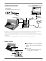
For IBM PC or PC compatible
For Macintosh
Serial connector
Printer port
Use a commercially available Phillips screwdriver to
tighten the screws at either end of the serial cable.
Modem port
Connect to either port.
Screw
Screw
Screw
Crossover
serial cable
(for Macintosh)
Serial connector
Crossover serial
cable
Included AC adapter
AC adapter jack
• During scanning, the table moves forward and backward. If the mounted scan object (the three-dimensional object to be scanned) is
larger than the table size, it may extend beyond the front and rear of the unit. Do not place any objects in the area.
• For the cable, use a commercially available crossover serial cable (RS-232C rating). A straight serial cable such as is commonly used
to connect a modem cannot be used. For more on how to connect a serial cable for Macintosh, see "15 Specifications -- Serial Cable
for Macintosh."
• Make sure the power to the computer and the PIX-30 is switched off before attempting to connect the cables.
Freeing the table
1
Before using the unit, remove the screws and the retainer
shown in the figure.
The table does not move if it remains secured in place by
the retainer. There are screws at two places at the front
and rear.
2
Remove the pad.
* The screws, retainer, and pad are necessary when
repacking the unit. Do not discard them.
Pad
Retainer
Screws
13
4
Installing the Dr.PICZA
Symbols used in the section on software
When the procedures for Windows and for the Mac OS are different, both are described. When the procedures are similar, the explanations use the screens for the Windows version. In such cases, the screen images may differ from those for the Mac OS version, but the
procedures do not change.
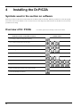
Overview of Dr. PICZA
A Quick Overview of Available Functions
Set scanning conditions and perform scanning
View scanned 3D data from various angles
Zoom in or out on the on-screen view of scanned data
Make settings for how scanned 3D data is displayed
Displays the coordinates of the scanned object
Color the faces of scanned 3D data
Edit scanned 3D data
Adjust the slant of scanned 3D data
Specify the data format and save the scanned 3D data
Launch the MODELA PLAYER
14
* For details, please refer to the help screens for Dr. PICZA.
Toolbar button
Installing
Setting Up the Windows Version of the Program
Operating environment
Dr.PICZA for Windows
Computer
Personal computer running Windows 95, Windows 98, or Windows NT 4.0
CPU
If you're using Windows 95: i486SX or better (Pentium 100 MHz recommended)
If you're using Windows 98 or Windows NT 4.0: i486DX or better (Pentium 100 MHz recommended)
System Memory
If you're using Windows 95: 8 MB or more (10 MB or more recommended)
If you're using Windows 98 or Windows NT 4.0: 16 MB or more (32 MB or more recommended)
Hard Disk
3 MB or more of free space
* When setting up the software under Windows NT 4.0, log on as the member of a group other than [Guest].
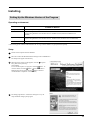
Setup
1
Switch on the computer and start Windows.
2
Place the CD from the Roland Software Package in the CD-ROM drive.
The Setup menu appears automatically.
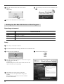
3
When the screen shown at right appears, click the
in [Click
here], then choose [PIX-30].
Click [Install].
To view the description of a program, click the
button. To
view the manual, click the
button. (There are manuals in
button references.
PDF format for the programs that the
Acrobat Reader is required to view PDF files.)
4
The Setup program starts. Follow the messages to carry out
setup and finish setting up the program.
15
5
7
6
When all installation finishes, the screen at below
appears.
Click [Close].
After returning to the menu screen for installation, click
.
Remove the CD-ROM from the CD-ROM drive.
Setting Up the Mac OS Version of the Program
Operating environment
Dr.PICZA for Mac OS
Computer
A Power Macintosh, or PowerBook with a PowerPC processor.
System
Mac OS 7.5 or higher
System Memory
20 MB or more (40 MB or more recommended)
Hard Disk
3 MB or more of free space
Setup
1
Turn off any virus-detection software.
2
Insert the Roland Software Package CD-ROM in the CD-ROM disk drive.
3
Double-click the CD-ROM icon.
5
When the screen shown right appears, click the allow in [Click
here], then choose [PIX-30].
Click [Install].
If there are programs you don't want to install, then clear their
check boxes before you click [Install].
6
The Installer's start screen appears. Follow the
messages to carry out setup and finish setting up the
program.
When installation is completed, remove the CD-ROM
from the CD-ROM drive.
16
4
Double-click the [Menu] icon.
5
Starting Dr. PICZA
For Dr. PICZA for Windows OS
For Dr. PICZA for Mac OS
Press the Start button
and select [Dr.
PICZA].
About Help
If you're unsure how perform an operation while you're working, taking a look at Help can find the answer. If you're using Dr. PICZA
for the first time, please be sure to read the Help screens. You can call up Help from the software menus.
For Dr. PICZA for Windows OS
For Dr. PICZA for Mac OS
17
6
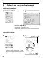
Selecting a communication port
For Dr. PICZA for Windows OS
1
From the [File] menu, click [Settings].
2
Select the port where the cable is connected, then click
[OK].
If You're Using Windows NT 4.0
If the printer port for Windows driver and the communication port for Dr. PICZA are
set to the same port, you cannot use Dr. PICZA.
To perform scanning, specify an unused port for the Dr. PICZA communication port.
For Dr. PICZA for Mac OS
1
Press the File button and select [Preferences...].
2
If Dr. PICZA selects the same communication port as
AppleTalk, the scanning cannot be processed. In this case,
please change the setting of Dr. PICZA so as to use another
port. Or, disable the AppleTalk.
18
Select the port where the cable is connected, then click
[OK].
Click either one or the other
7
Powering ON
NOTICE
Before switching on the power to the PIX-30, turn on the computer.
Press the STANDBY key.
The STANDBY LED lights up, and origin detection by
the sensor starts.
- During origin detection immediately after switching on the power, the PIX-30 may beep for
approximately 10 seconds, but this does not
indicate a problem.
When the sound stops, the table moves, and
when the sound indicating the end of the
detection operation is heard, detection is
finished.
- During origin detection immediately after
switching on the power, an error is displayed if
some object touches the sensor. (When an
error has occurred, the STANDBY LED intermittently flashes twice.)
If this happens, switch off the power, remove the
object touching the sensor, then switch the
power back on.
8
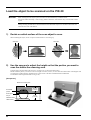
Load the object to be scanned on the PIX-30
The sensors for the PIX-30 are highly sensitive, and can even scan three-dimensional objects made out of clay.
You can usually perform scanning if the three-dimensional object is of a composition and configuration that can retain its shape.
However, the pressures that the sensors detect are from several grams to several tens of grams, so you cannot scan objects whose shape
changes when touched by the sensors. (Pressure may fluctuate, depending on the composition of the object being scanned.)
For instance, it may not be possible to scan something like a fuzzy stuffed animal.
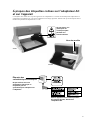
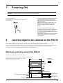
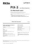
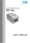
Maximum scanning area of the PIX-30
The maximum scanning area is shown in the figure.
The grid on the table serves as a guide for mounting the object to scan.
It does not indicate the scanning area for Dr. PICZA.
304.8 mm (12 in.)
The scale is in 10 mm (3/8 in.) units.
Maximum
scanning area
Upper surface
203.2 mm
(8 in.)
Front surface
60.5 mm (2-3/8 in.)
10 mm (3/8 in.)
* This space cannot be scanned.
70 mm (2-6/8 in.)
Table surface
Spacer
30 mm (1-3/16 in.)
Spacer
30 mm (1-3/16 in.)
19
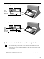
Load the object to be scanned on the PIX-30
NOTICE
When securing the scan object in place, be sure to use the included clay or adhesive sheet.
Do not use double-sided tape or other strongly adhesive materials. Such materials may cause the table surface
to peel.
During scanning, the table moves forward and backward. Mount the object to be scanned so that it does not
touch the inner wall of the PIX-30.
1)
Decide on which surface of the scan object to scan.
When mounting the object, secure it in place with the surface to scan facing up.
Scan face
2)
Scan face
Use the spacers to adjust the height so that the portion you want to
scan lies within the scanning area.
Scanning cannot be performed in the area up to 70 mm (2-3/4 in.) above the table surface.
Mount so that the portion you want to scan is at a height of 70 mm (2-3/4 in.) or more above the table surface. If the height is still
not enough even when using the included spacers, place a book or the like of suitable thickness underneath.
The maximum load weight of the table is 5 kg (11 lb.).
[No spacers]
Maximum scanning area
Scannable
portion
60.5 mm
(2-3/8 in.)
Scan object
Clay or
adhesive sheet
Table surface
20
70 mm
(2-3/4 in.)
[When using a single spacer]
Maximum scanning area
60.5 mm
(2-3/8 in.)
Scannable
portion
Scan object
40 mm
(1-9/16 in.)
Clay or
adhesive sheet
30 mm
(1-3/16 in.)
Spacer
Table surface
* If the scan object protrudes beyond the spacer, use two spacers side by side.
[When using two spacers]
Maximum scanning area
60.5 mm
(2-3/8 in.)
Scannable
portion
10 mm
(3/8 in.)
Scan object
Clay or
adhesive sheet
Spacer
Spacer
Table surface
30 mm (1-3/16 in.)
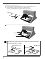
3)
Use clay or on adhesive sheet to secure the scan object in place.
- When securing the scan object in place on the table, do not use commercially available cellophane tape or doublesided tape. When the tape is peeled off, the coating on the table surface may peel as well.
- When not using the adhesive sheet, store it with the backing paper affixed to the adhesive surface.
- Do not wash the adhesive sheet with water. Doing so may damage the adhesive surface, making it impossible to hold
a scan object in place.
A scan object which does not topple over when placed with the scan surface facing up is suited to being held in place by the
adhesive sheet. For other shapes, use clay to secure in place.
21
Securing in place with adhesive sheet
1
Peel off the backing paper from both sides of the adhesive sheet, and affix the sheet to the table or a spacer.
* Do not discard the backing paper. It is needed for storing the adhesive sheet after use.
* If necessary, you can also cut the sheet to match the size of the scan object and spacers.
* There is no need to use an adhesive sheet to between spacers or between the table and a spacer.
Adhesive sheet
Peel off the backing paper.
Table
2
Place the scan object on the adhesive sheet, and gently press it down to secure it in place.
Scan object
Adhesive sheet
Table
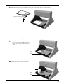
When an adhesive sheet is applied to the table and a highly smooth surface of the scan object is stuck on the sheet, it
may sometimes be difficult to peel off the object.
To secure in place, use clay or cut small pieces of adhesive sheet (about 1 cm (3/8 in.) square), and affix them to the
four corners of the bottom surface of the scan object.
Bottom surface of the scan object
No Good
Scan object
Adhesive sheet
Table
Table
22
Adhesive sheet
3
When finished scanning, peel off the adhesive sheet, then affix the backing paper to the sheet and store it.
Adhesive sheet
Affix the backing paper.
Securing in place with clay
1
Make a base on the table or spacer using clay.
* There is no need to use an adhesive sheet to
between spacers or between the table and a
spacer.
Clay
Table
2
Press the scan object into the clay to hold it in
place.
Scan object
Clay
Table
23
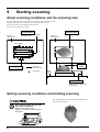
9
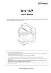
Starting scanning
About scanning conditions and the scanning area
For information about the setting items for Dr. PICZA, refer to the figures below.
The grid on the table serves as a guide for mounting the object to scan.
It does not indicate the scanning area for Dr. PICZA.
The scale is in 10-mm (3/8 in.) units.
Y SCAN PITCH
(Spacing of adjacent scan points
along the Y axis)
Maximum
scanning area
Scanning Area
Maximum
scanning area
Scanning area
Scan object
X SCAN PITCH
(Spacing of adjacent scan
points along the X axis)
: Scan path
(Draft scanning)
: Scan points
Z Upper
Limit
Table
surface
Z BOTTOM
(Height of the scanning area's
bottom plane)
Setting scanning conditions and starting scanning
The explanations here and after are based on samples like
those shown in the figures.
Do not place hands near the main
unit while in operation.
Doing so may result in injury.
Doing so may lead to faulty operation or
breakdown.
24
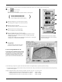
Make the settings for scanning resolution, the minimum height of the surface to be scanned, and the scanning quality.
1
Click
on the Dr. PICZA.
The Controller window opens.
When Dr. PICZA is started, the Controller window is already open.
(
For Dr. PICZA for Mac OS
Open the [File] menu and choose [New].
2
)
2
2
3
Make the settings for X scan pitch and Y scan pitch.
The setting in this example is for 0.50 mm (0.020 in.).
3
Make the setting for Z bottom.
The setting in this example is for 85 mm (3.346 in.).
4
4
Make the selection for scanning quality.
Here, click [Fine] to activate this setting.
5
Here, click [Smart Scan] to activate the setting.
When the [Smart Scan] setting is on, clicking [Scan] makes the PIX-30
automatically restrict the scanning area (on the X-Y plane only) before
scanning is performed.
To specify the scanning area, turn off [Smart Scan] and refer to "Setting the
scanning area" to make the desired settings.
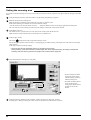
6
5
6
For detailed description of the available
Controller buttons, please refer to the help
screens for Dr. PICZA.
Click [SCAN] .
Scanning starts.
(During scanning, the sensor may emit a
transmission sound, but this is normal.)
If You're Using Windows NT 4.0
If the printer port for Windows driver and the
communication port for Dr. PICZA are set to
the same port, you cannot use Dr. PICZA.
To perform scanning, specify an unused
port for the Dr. PICZA communication port.
Use the following examples as a guide to determine the amount of computer memory required to perform scanning.
* The figures shown below are the amounts used by Dr. PICZA alone. They do not take into account the amounts used by the operating
system or other programs.
Example: Required memory when scanning a 100 mm x 100 mm (3-15/16 in. x 3-15/16 in.) area
- Scanning at a pitch of 0.05 mm x 0.05 mm (0.002 in. x 0.002 in.) :
- Scanning at a pitch of 0.1 mm x 0.1 mm (0.004 in. x 0.004 in.) :
- Scanning at a pitch of 0.5 mm x 0.5 mm (0.020 in. x 0.020 in.) :
Approx. 2 GB
Approx. 500 MB
Approx. 20 MB
25
Setting the scanning area
If you wish to limit the scanning area, such as in cases where you wish to scan only a portion of an object, make the settings as described
below.
1
Click [Scanning Area] in the Controller window. The [Scanning Area] dialog box appears.
2
Make the settings for the scanning area.
Make the settings to match the location where the scan object is secured in place.
Either of the following two methods can be used to make the settings.
- Use the mouse to move the blue frame on screen.
- Enter the numerical values for the upper-right and lower-left points.
The size of the on-screen scanning area (shown in blue) changes to match the values that are entered.
3
Click [Begin Area Test].
The sensor moves to a position above an outer point on the scanning area that has been set.
Make sure the scan object that has been secured in place lies within the area.
4
Click [Z Upper Limit].
The cursor
is displayed on the Z upper-limit setting on screen.
Specify the highest position of the scan object. Clicking [Apply] or double-clicking on the target lowers the sensors to the target's
center position.
If the target is displaced, redo the settings.
* Set the Z upper limit to the highest position on the object to be scanned.
During scanning, if the sensor detects a position higher than the Z upper-limit setting, the setting is cleared and
scanning continues with the greatest scan height of Dr. PICZA as the Z upper limit.
5
After determining the scanning area, click [OK].
5
• For the scanning area and Z
upper limit, please refer to
"About scanning conditions
and the scanning area".
4
• For details about the buttons
on the scanning-region
setting screen, please refer to
the help screens for Dr.
PICZA.
2
4
3
4
6
26
Check the scanning conditions in the Controller window one more time, then click [SCAN] .
Scanning starts. (During scanning, the sensor may emit a transmission sound, but this is normal.)
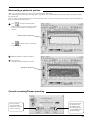
Rescanning a particular portion
After you’ve scanned an object, you can rescan a particular portion of the object.
After performing coarse scanning for the entire object, respecifying only an included portion and performing fine scanning can shorten
the scanning time.
However, if the scan object has been moved or removed from the table, or if the power to the PIX-30 has been switched off and back on,
then you cannot scan the same portion.
1
Click
, and from the scanning data
shown on the screen, select a portion to rescan.
You can specify a number of noncontinuous
portions.
Specify area for rescanning
Click
on the Dr. PICZA. The Control-
ler window opens.
3
Make the setting for scanning conditions.
4
Click [SCAN].
Rescanning of the specified portion starts.
Results of rescanning
Cancels scanning/Pauses scanning
Cancels scanning.
Any data scanned
before being canceled
remains in memory.
Scanning pauses and
the sensor moves to
the VIEW position
(the inner-right area).
Click [VIEW] again to
resume scanning.
27
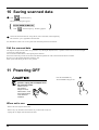
10 Saving scanned data
1
Click
and choose [Save] .
The [Save As] dialog box appears.
(
2
For Dr. PICZA for Mac OS
Click
and choose [Save]. The dialog appears.
)
Choose the desired location for saving the file, enter a file name, and click [SAVE].
The extension ".pix" is appended to the file name.
For information on how to save a file, please refer to the help screens for Dr. PICZA.
Edit the scanned data
The shape of an object can be edited. It is possible to vary the height, adjust the slant, or perform concave/convex inversion (height
inversion) for a desired surface.
You can use the toolbar button or select [Edit] on the menu bar.
Please refer to the help screens for Dr. PICZA for detailed explanations of the various functions that are available.
Be sure to save the scanned data before starting to edit.
When you're done editing, be sure to save your file.
11 Powering OFF
Press the STANDBY key.
The STANDBY LED goes out.
When not in use for extended
periods, unplug the AC adapter from
the electrical outlet.
Failure to do so
may result in
danger of shock,
electrocution, or fire
due to deterioration
of the electrical
insulation.
When not in use
- Remove the scan object from the table.
- Remove any clay from table, and store the clay so that it will not dry out.
- Unplug the AC adapter from the electrical outlet.
28
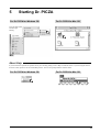
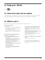
12 Ending Dr. PICZA
Crick the
button.
13 Items that may not be copied
Unauthorized reproduction of a copyrighted item for any purpose other than personal use may be a violation of copyright. Roland DG
Corp. will not be responsible for any violation of third-party copyright by any article made through use of this product.
14 What to do if...
If you want to completely stop the operation of the PIX-30, detach the AC adapter from AC outlet.
The PIX-30 doesn't operate
Check the following.
- Is the STANDBY key on (with the STANDBY LED lit
up)?
- Are the settings for the computer and software correct?
- Are the cable connected correctly?
- Have the retaining screws and the retainer for the table
been removed? (Refer to "3 Setting up and connection".)
The STANDBY LEDs repeatedly flashes once
This indicates a communications error.
Switch off the power and check the following.
- Are the communications port settings made for Dr.
PICZA correct?
- Are the connections for the AC adapter and the cable
connecting the unit to the computer secure?
- Are the AC adapter and the cable connecting the unit to
the computer free of any internal broken wires?
- Is the operation of the computer correct?
- Was the power to the computer switched on before the
PIX-30 was turned on?
Be sure to power up the computer first, then switch on
the power to the PIX-30.
- Was the computer restarted?
When the computer has been restarted, switch the
power to the PIX-30 off, wait a few seconds, then
switch it back on.
The STANDBY LEDs repeatedly flashes twice
Something touched the sensor during initial operation
immediately after switching on the power, or a hardware
error occurred.
If there is an obstruction, then switch off the power, remove
the obstruction, and switch the power back on.
If there was a hardware error, then switch the power off and
back on and repeat the same operation.
If the same error display occurs, consult your authorized
Roland dealer or service center.
Pressing the STANDBY key does not switch off the
power.
Unplug the AC adapter from the unit.
The tip of the sensor was inadvertently bent
Please contact your authorized Roland DG Corp. dealer or
service center.
29
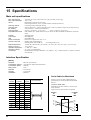
15 Specifications
Main unit specifications
Max. scanning area
Max. table load weight
Sensor
: 304.8 mm (12 in.) [X] x 203.2 mm (8 in.) [Y] x 60.5 mm (2-3/8 in.) [Z]
: 5 kg (11 lb.)
: Roland Active Piezo Sensor (R.A.P.S.)
Probe length 64 mm (2-1/2 in.), tip bulb diameter 0.08 mm (0.00315 in.)
: Contacting, mesh-point height-sensing
: X/Y-axis directions -- 0.05 to 5.00 mm (0.002 to 0.20 in.) (settable in steps of 0.05 mm (0.002 in.))
Z-axis direction -- 0.025 mm (0.000984 in.)
: X/Y-axis -- 30 mm/sec. (1-1/8 in./sec.)
Z-axis -- 9 mm/sec. (5/16 in./sec.)
: DXF, VRML, STL, 3DMF, IGES, Grayscale, PICT (for Mac OS), BMP (for Windows), and Point
Group
: Serial (RS-232C)
: STANDBY key
: STANDBY LED
: Exclusive AC adapter (DC+12V 1.5 A)
: Standby mode: under 40 dB (A)
Scanning mode: under 50 dB (A)
(According to ISO 7779)
: 478 mm (W) x 465 mm (D) x 341 mm (H) (18-7/8 in. (W) x 18-5/16 in. (D)) x 13-7/16 in. (H))
: 11 kg (24.2 lb.)
: 5—40°C (41—104°F)
: 35—80 % (no condensation)
: Roland Software Package CD-ROM: 1, AC adapter: 1, clay: 1, adhesive sheets: 2, spacers: 2, PIX-30
user's manual: 1
Scanning method
Scanning pitch
(Dr. PICZA)
Scanning speed
Exportable file formats
Interface
Control keys
LED
Power consumption
Acoustic noise level
External dimensions
Weight (unit only)
Operation temperature
Operation humidity
Accessories
Interface Specification
[Serial]
Standard
Transmission method
Transmission speed
Parity Check
Data Bits
Stop Bits
Handshake
:
:
:
:
:
:
:
RS-232C specifications
Asynchronous, duplex data transmission
9600 bps
None
8 bits (fixed)
1 bits (fixed)
Hardwire
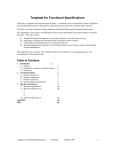
Serial Cable for Macintosh
Signal
number
30
Terminal
number
Signal
number
NC
25
13
NC
NC
24
12
NC
NC
23
11
NC
NC
22
10
NC
NC
21
9
NC
DTR
20
8
NC
NC
19
7
SG
NC
18
6
DSR
NC
17
5
CTS
NC
16
4
RTS
NC
15
3
RXD
NC
14
2
TXD
1
FG
Pin connection
Prepare a crossover cable with the following
specifications to connect the Macintosh and the
PIX-30.
Crossover serial cable
Mini-DIN 8-pin male connector - D-sub 25-pin
male connector
Apple crossover cable (JCRC01 compliant)
Mini-Din
8P
GND
D-sub25P
25P
GND
2
3
4
5
2
3
4
5
6
7
8
20
Please read this agreement carefully before opening the sealed
package or the sealed disk package
Opening the sealed package or sealed disk package implies your acceptance of the terms and conditions of this agreement.
If you do NOT accept this agreement, retain the package UNOPENED. (This product is just one of included items. Please
be aware that any amount of the purchase price will not be refunded for return of this product as a single item, regardless
of whether the package is opened or unopened.) The enclosed Roland product is a single user version.
Roland License Agreement
Roland DG Corporation ("Roland") grants you a non-assignable and non-exclusive right to use the COMPUTER
PROGRAMS in this package ("Software") under this agreement with the following terms and conditions.
1. Coming into Force
This agreement comes into force when you purchase and open the sealed package
or sealed disk package.
The effective date of this agreement is the date when you open the sealed package
or sealed disk package.
2. Property
Copyright and property of this Software, logo, name, manual and all literature
for this Software belong to Roland and its licenser.
The followings are prohibited :
(1) Unauthorized copying the Software or any of its support file, program module
or literature.
(2) Reverse engineering, disassembling, decompiling or any other attempt to
discover the source code of the Software.
3. Bounds of License
Roland does not grant you to sub-license, rent, assign or transfer the right granted
under this agreement nor the Software itself (including the accompanying items)
to any third party.
You may not provide use of the Software through time-sharing service and/or
network system to any third party who is not individually licensed to use this
Software.
You may use the Software by one person with using a single computer in which
the Software is installed.
4. Reproduction
You may make one copy of the Software only for back-up purpose. The property
of the copied Software belongs to Roland.
You may install the Software into the hard disk of a single computer.
5. Cancellation
Roland retains the right to terminate this agreement without notice immediately
when any of followings occurs :
(1) When you violate any article of this agreement.
(2) When you make any serious breach of faith regarding this agreement.
6. Limitations on Liability
Roland may change the specifications of this Software or its material without
notice.
Roland shall not be liable for any damage that may caused by the use of the
Software or by exercise of the right licensed by this agreement.
7. Governing Law
This agreement is governed by the laws of Japan, and the parties shall submit to
the exclusive jurisdiction of the Japanese Court.
R5-000707