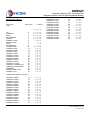
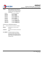
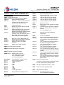
1
Connectivity Beyond Limits DAVICOM Semiconductor, Inc. DM562P Integrated Data/Fax/Voice/Speakerphone Modem Operation Manual & AT Command Set Version: DM562P-MA-P01 August 20, 2002 DM562P Operation Manual & AT Command Set Integrated Data/Fax/Voice/Speakerphone Modem Contents Chapter 1: Introduction ■ Introduction ■ Modem Package ■ The Data/Fax/Voice/Speakerphone External Modem Chapter 2: Installation ■ Selecting a Communication Port ■ Installing the Modem ■ Connecting the Modem to the Telephone Line ■ Installing a Software Package ■ Checking the Installation ■ Initialization String Set-up Chapter 3: AT commands and S Registers ■ Functional States ■ Configuration Profiles ■ AT Command Syntax ■ AT Command set Part I: Data command a. General Command b. V.42bis / MNP 5 Command c. Result Code Part II: Fax Command a. Fax Class 1 Command Part III: Voice Command a. Voice Command b. Shielded Command Part IV: S Registers ■ Status Register Summary Chapter 4: Troubleshooting ■ Software Settings ■ Troubleshooting Procedures 2 Preliminary Version: DM562P-MA-P01 July 12, 2000 DM562P Operation Manual & AT Command Set Integrated Data/Fax/Voice/Speakerphone Modeml FCC Regulations FCC part 68: Requirements for End Users The following FCC rules must be observed when using the Modem. The modem must not be connected to a party line (a telephone line shared by two or more subscribers) or coin-operated telephone. If trouble is experienced, the modem must be disconnected from the telephone line to determine the cause of the problem and may be reconnected only after the problem is corrected. The modem must not replace your telephone. There must be at least one telephone connected to your telephone line. If you have only one telephone wall outlet, you can satisfy this requirement by connecting your telephone to the PHONE jack on the modem. You must notify your local telephone company that you will be installing an FCC registered device on your telephone line. If requested, you must provide the telephone company with the following information: • The telephone number of the line connected to your modem. • • The FCC registration number: or • • The FCC ID: or • The ringer equivalence number: FCC Part 15: Radio/TV Interference The equipment described in this manual generates and uses radio frequency energy and if not installed and used properly (that is, in strict accordance with the manufacturer instructions) may cause interference to radio and television reception. This equipment has been tested and complies with the limits for Class B computing devices in accordance with the specifications in Subpart J, Part 15, of FCC rules. These rules are designed to provide reasonable protection against such interference in a residential environment. However, there is no guarantee that interference will not occur in a particular installation. If this equipment does cause interference to radio or television, which can be determined by turning the equipment off and on, the user is encouraged to try to correct the interference by one or more of the following measures: Preliminary Version: DM562P-MA-P01 July 12, 2000 • Reorienting the receiving antenna • Relocating the modem with respect to the receiver • Moving the modem away from the receiver • Plugging the modem into a different outlet so that the modem and receiver are connected to different branch circuits. If necessary, the user should consult the dealer or an experienced radio/television technician for additional suggestions. Users may also wish to consult the booklet ow to Identify and Resolve Radio-TV Interference Problems” prepared by the Federal Communications Commission. This booklet is available from the U.S. Government Printing Office, Washington, D.C. 20402, Stock No. 004-000-00345-4. FCC Requirements for Consumer Products (1) This equipment complies with Part 68 of the FCC rules. On the side of this equipment is a label that contains, among other information, the FCC registration number and Ringer Equivalence Number (REN) for this equipment. If requested, provide this information to your telephone company. (2) The REN is used to determine the quantity of devices you may connect to your telephone line such that all of the devices ring when the number is called. In most, but not all areas, the sum of the RENs of all devices should not exceed five (5.0). To be certain of the number of devices you may connect to your line, as determined by the REN, call your company to determine the maximum REN for your calling area. (3) If your modem causes harm to the telephone network, the telephone company may discontinue your service temporarily. If possible, the telephone company will notify you in advance. If advance notice is not possible, you will be notified as soon as possible. You will be advised of your right to file a complaint with the FCC. (4) Your telephone company may make changes in its facilities, equipment, operations, or procedures that could affect the proper operation of your equipment. 3 DM562P Operation Manual & AT Command Set Integrated Data/Fax/Voice/Speakerphone Modem If such changes are planned, you will be given advance notice so as to give you an opportunity to maintain uninterrupted service. (5) If you experience trouble with this modem, contact your dealer for repair/warranty information. The telephone company may ask you to disconnect this equipment from the network until the problem has 4 been corrected or you are sure that the equipment is not malfunctioning. (6) Repairs that customers can make include replacing fuses or plug-in cards. (7) This equipment may not be used on coin service telephones provided by the telephone company. Connection to party lines is subject to state tariffs. Preliminary Version: DM562P-MA-P01 July 12, 2000 DM562P Operation Manual & AT Command Set Integrated Data/Fax/Voice/Speakerphone Modeml Chapter 1: Introduction Introduction This Data/Fax/Voice/Speakerphone Modem Is a personal computer external modem, special made for the RS-232 com port in the IBM compatible Personal computers. It supports the Plug and Play (PnP) function to make the installation real easy for you. As a data modem, it serves as a communication link between your computer and a remote computer, allowing you to transmit or receive data over the telephone lines. And it is compatible with the ITU-T V.90 (56,000 bits per second), ITU-T V.34+ (33,600 bits per second), CCITT V.32bis, V.32, V.22bis, V.22, V.21, and Bell 103, 212 standards, and provides line speeds from 56000 bits per second to 300 bits per second. However, due to FCC rules which restrict power of internet service provider modem, current download speeds are limited to 53Kbps. As a Fax modem, it lets you to use your computer as a fax machine, transmitting documents to and receiving them from remote fax machines and/or fax modems. It is compatible with CCITT V.17, V29, V.27ter and Group 3 Fax standards, provides line speeds from 14,400 to 2,400 bits per second, and sends and receives faxes using class 2 fax commands. As Voice modem (if hardware supports), it provides the answer machine functions, recording a voice message, playing pre-recorded message back, and recording the message from remote telephone users. As Speakerphone modem (if hardware supports), it provides the all functions as Voice modem above and with external speaker and microphone, it provides user the hand free and conference speaker phone functions. Modem Package In addition to the modem itself, the modem package includes the following: • This user's manual • A communication software package (including a manual) • A RS-232 Cable • An RJ-11C phone cord • A setup floppy diskette • A warranty card After you unpack the modem, check it for shipping damage. Rough handling during shipping causes most early modem failures. If you notice any damage, contact your dealer. The Modem Before reading chapter 2, which describes how to install the modem, take a moment to examine the jacks on the rear of the modem. There are two jacks on the rear of the modem. One is labeled as "LINE", which is to plug in the supplied RJ11C phone cord and the other end is to plug into the phone jack in the wall. The other jack is labeled as "PHONE", which is to connect your telephone set to the modem or your other telephone devices, so that you may use the same wall jack for both the modem and the devices you original use without change your original telephone device setup. Please refer to FCC Regulations at the beginning of this manual for the important rules and Ringer Equivalence Number (REN) information. The Modem functions as a 56,000 bits per data modem, a 14,400 bits per second fax modem with 115,200 bits per second data rate to and from your computer. This manual explains how to set up and install the Modem and operates the modem using the AT command set. Preliminary Version: DM562P-MA-P01 July 12, 2000 5 DM562P Operation Manual & AT Command Set Integrated Data/Fax/Voice/Speakerphone Modem Chapter 2: Installation This chapter explains how to install your modem and check whether it is working correctly. To install the modem you need to perform the following simple steps: 1. 2. 3. 4. 5. 6. 7. 8. Turn off your computer and any attached devices, such as a printer. Connect the serial cable to the modem and to the computer. When looking for the serial port on the back of your computer, look for labels marked COM1 or COM2. Plug and the power adapter into a standard wall outlet and insert its plug into the power jack on the modem. Connect the modem to the telephone line in the wall jack. If you wish, you may also connect a telephone set or your telephone devices to the modem through the "PHONE" jack on the modem. Turn on your modem, then turn on your computer and Peripherals. Set up your modem. a. For Windows 95/98 and NT, follow "New Hardware Found" window to complete the installation of modem. b. For other system, please refer to the following specified procedures. Install a communication software package and setup the software to operate the modem. Checking the Installation. Each of these steps is explained in details below. 1. Turn off computer and attached devices. 2. Connect the serial cable The serial cable may be 9-pin or 25-pin. 3. Plug the power adapter Warning! Do not use other adapter not offered by original Manufacturer. 4. Connect the Modem to the Telephone Line Once the modem is installed in your computer, you are ready to connect the modem to telephone jack on the wall. To connect the modem to the telephone line, plug one end of provided RJ-11C phone cord in the modem package into the jack, marked as "LINE" jack on the bracket of the modem, and the other end of phone cord to the phone jack in the wall. 6 If you wish, you may connect a telephone set or your telephone devices to the modem so that both modem and your telephone devices are connected to a single wall jack. To connect your telephone devices to modem, simply plug the modular phone cord of your telephone devices into the "PHONE" jack on the bracket of the modem. 5. Turn on the modem and PC 6. Setup your modem 6.a Windows 95 or Windows NT If your system OS is either Windows 95/98 or Windows NT, after the step 7, Power up your computer, you will notice that your computer display "New Hardware Found" window to prompt you to setup the new hardware, namely, modem. Follow the prompt and choose "Have Disk" option, insert the floppy diskette in the package in the drive and select that drive. Click OK. your modem is automatically set up. 6.b Windows 3.x or DOS 1. If your system is not provide the Plug and Play (PnP) functions, such as Windows 3.x or DOS, the COM port is decided by the com port you connected 7. Installing a Software Package Once you have the external modem, you can install a communication software package on your computer. ( A software package is provided with the modem. Of cause you may use a different software package of your choice.) You will need the communication software to operate the modem. (The modem may also be operate by using the AT commands, described later in this manual.) When configuring the software applications, take note of the following: 1. The setting for "baud rate" in the software application should be set to 115,200, the highest supported by the modem. Unless you have special reason not to. This setting refers to DTE speed ( the speed with which your computer communicates with the modem), not the speed of the modem supported for connection with other modems. 2. Select "RTS?CTS" or "hardware " flow control handshaking in the software application. This will guarantee the sent data and received data can be handled by your computer, without lose any of data. Preliminary Version: DM562P-MA-P01 July 12, 2000 DM562P Operation Manual & AT Command Set Integrated Data/Fax/Voice/Speakerphone Modeml 3. 4. If you are using Microsoft Windows, check the port parameters in the Control Panel. Select "hardware" and the appropriate baud rate. If you are using a software package other than the one included with your modem and the name of your modem does not appear on the modem list in the software, choose either "generic" or "Hayes compatible" for the type of modem. Select "error correction" if it is available. 8. Checking the Installation If you have a telephone set connected to the modem, pick up the receiver and check whether you hear a normal dial tone. If you do not, confirm that the wall line is properly connected to the modem and that the telephone set is plugged securely into PHONE jack on the modem. You may like to check the modem is properly set up or not. Here is what you have to do. 8.a Windows 95/98 or Windows NT 1. 2. 3. 4. 5. 6. 7. 8. 9. 10. 11. 12. 13. 14. Click START, Move mouse to SETTINGS, Click on CONTROL PENAL, Double click on the MODEMS icon, MODEMS PROPERTIES shows up, Select GENERAL tab, you should see the new modem is added to the list. Select DIAGOSTICS tab, you will see the new modem is list on one of the port. Close MODEMS PROPERTIES, Close CONTROL PENAL, Click START again, Move mouse to PROGRAMS, ACCESSORIES, HYPER TERMIANL, Double click HYPERTRM.EXE, NEW CONNECTION - HYPER TERMINAL and CONNECTION DESCRIPTION windows show up, Follow the prompt to make your first connection. can not enter terminal mode, the communication port setting of modem may conflict with that of another serial device in your system. In this case, you will need to adjust the settings to different one. If the "AT" is not displayed when you type it, the local echo function may be off. To turn it back on, type "ATE1" and carriage return. If double characters appear on the screen, both your modem and software are set to local echo on; in this case disable the local echo function in your software application, or you can type "ATE0" and carriage return to turn the modem's local echo off. If you suspect a problem with modem or the telephone line after installation, disconnect the modem until you determine the source of the problem. Initialization String Set-up The following initialization string is suitable for most applications. You may make additions as appropriate. AT &F E0 V1 &D2 &C1 \V1 S0=0 <cr> Note: a. Some application program does not allow for spaces between commands. b. Some application program may have to replace carriage return to ^M or a\ to the end of string. c. Some commercial service nodes do not like data compression. If you do not connect or connections is sluggish, include %C0 to disable the data compression. 8.b Windows 3.x or DOS Run the communication software provided with the modem. Put the computer in terminal emulation mode, so that the computer functions as a terminal. To check whether your computer and modem are communicating properly, either enter "AT" and carriage return. The modem should respond by displaying the letters "OK" one the computer screen. If the modem does not respond or if the software Preliminary Version: DM562P-MA-P01 July 12, 2000 7 DM562P Operation Manual & AT Command Set Integrated Data/Fax/Voice/Speakerphone Modem Chapter 3: AT commands and S Registers Functional States Configuration Profiles AT Command Syntax AT Command Summary AT Command set Status Register Summary AT Command Set Result Codes Example Other Important Settings The modem supports an extended Hayes AT command set that allows you to adjust the modem's operating parameters and initiate calls. This chapter describes how to operate the modem from a personal computer or a terminal keyboard using AT commands. Functional States In AT command operating environment, the modem has four functional states: The command state, The wait-for-carrier state, The on-line state, and The on-line command state. In the command state, the modem accepts AT commands form the terminal, allowing you to configure the modem and dial telephone numbers. When the modem is powered on, it defaults to the command state. After modem dials a number, it enters a transition state, called the wait-for carrier state and waits for a carrier signal from the remote modem. If the modem does not detect a carrier signal within a preset time period (this period is defined by the value of S7 register), it abandons the call and re-enters the command state. You can also cause the modem to exit the wait-forcarrier state and return to the command state by pressing any key on the keyboard, causing a dial abort action. If modem detects a valid carrier signal, it connects with the remote modem, according to the best negotiation speed decided by both modems, and enters the on-line state. In this case, the modem transmits data asynchronously. If the carrier signal is lost or intentionally dropped the connection, the modem hangs up and re-enters the command state. 8 While the modem is on line, you can temporarily exit the on-line state, and enter the on-line command state, from which limit set of AT commands can be entered to interrogate the modem current settings and make sure the connection is what is supposed to be and to disconnect the line gracefully. To enter the on-line command state, wait 1 second, type +++, wait another 1 second, and type AT, carriage return (this procedure is called Time Independent Escape Sequence, TIES). The first valid AT commands entered while the modem in the on-line command state will be executed just as they would be executed in the command state. If the first command is Invalid in this state, it will cause modem be to on-line state and you will have on-line connect message shown on the screen. After the first command is accepted and in the on-line command state, the rest AT commands will accepted with OK or rejected with ERROR and stay in this state until 1. You issue ATO command to re-enter the on-line state, 2. You issue ATH to drop the connection and back to command state, 3. Connection is disconnected and the modem go back to command, 4. Application program request modem to disconnect and go back to command state. Configuration Profiles A configuration profile refers to a complete set of operation parameters for the modem. The operating parameters in use at any one time are referred to as active profile. The active profile is stored in RAM in the modem and it may be viewed by entering AT&V. Each time the modem powers up, the active profile is loaded with profile 0 or 1 at the time modem was last powered off You can store the active profile into profile 0 or profile 1 and into the non-volatile memory (EEPROM) by entering AT&W0 or AT&W1. So next time the modem is powered up, you can assume the profile while you left off. The factory default profile, which is stored in ROM in the modem, consists of the operating parameters most commonly used for data communication and is satisfactory for the needs of most users. The default profile can be reload into active profile by entering AT&F. Preliminary Version: DM562P-MA-P01 July 12, 2000 DM562P Operation Manual & AT Command Set Integrated Data/Fax/Voice/Speakerphone Modeml AT Command Syntax With two exceptions, all AT commands are prefixed with AT (uppercase or lowercase, even, odd, none, mark or space parity do not matter), which stands for "ATtention", command body, list in the following sections, and command line terminator, most commonly used is carriage return. The two exceptions are the "A/" command, which is used to repeat the last command, and the "+++", which cause modem goes into on-line command state. There are 40 characters length limitation post on every single command line. Any command line exceeds this limitation will result an ERROR result. Preliminary Version: DM562P-MA-P01 July 12, 2000 9 DM562P Operation Manual & AT Command Set Integrated Data/Fax/Voice/Speakerphone Modem feature and prevent you from returning to the Command Mode. Please refer to S2 and S12. AT Command set PART I : Data COMMAND SET General Command A/ Repeat the last executed AT command Do not precede A/ with AT or follow with ENTER. AT Attention Characters. 'AT' character pairs always at the beginning of each command line, except 'A/', which is to repeat the last executed AT command. Note: The following commands always have to precede with 'AT' attention character pair, if it is the first command in the command line. A Manually answer incoming call. D Dial (Originate a Call). The following modifiers can be used in the dial string: 0-9,#,* Dialing digits. Touch Tone dial characters. P Pulse dialing. T Touch Tone dialing. W Wait for second dial tone. , Pause (programmable by S8). ^ Enable 1300 Hz calling tone. ! Flash (delay 500 ms). ; Return to command mode. DS=n Dial stored number. Dials one of three telephone numbers (n = 0,1 or 2) which is stored in the modem's nonvolatile memory via AT&Zn=x command. En E0 E1* Command Echo. Disables command echo. Enables Command echo. +++ Default Escape Character. To switch from data mode to command mode, you can pause one second and type '+++'. Do not follow with carriage return. The default ASCII character '+' is decimal 43. You can change register S2 to any value from 0 to 255. Values greater than 127 disable the escape 10 Hn H0* H1 Hook control. Modem is on-hook (disconnect from line). Modem is off-hook (connect to line). In I0* I1 I2 I3 I4 Identification. Display product-identification code. Factory set. Internal memory test. Firmware version 1. Firmware version 2. Ln L0 L1* L2 L3 Volume Control. Speaker volume off. Low speaker volume. Medium speaker volume. Loud speaker volume. Mn M0 M1* M2 M3 Speaker Control. Speaker off. Speaker on until carrier detected. Speaker always on. Speaker on until carrier detected and off while dialing. Nn N0 Auto mode Selection. Disable auto mode. Modem connect speed is fixed according to AT*Nn setting. Enable adaptive connect speed (always connect at the highest compatible speed). N1* On O0* O1 Return to Data Mode Selection. Return to Data Mode. Return to Data Mode and initiate a retrain. Qn Q0* Q1 Modem Response Selection. Modem sends responses. Modem does not send responses. Sr? Reads Register r Value. r is 0 to 97. Sr=n Set Register r to Value n. r is 0 to 97, n is 0 to 255. Un U0 U1 U2 U3* V.34 Control. Disable V.34 when AT*N1 - AT*N6. Enable V.34. Enable V.34 aggressive connection Enable V.90 Preliminary Version: DM562P-MA-P01 July 12, 2000 DM562P Operation Manual & AT Command Set Integrated Data/Fax/Voice/Speakerphone Modeml Vn V0 V1* Responses Selection. Numeric responses. Verbose (text) responses. &D3 Modem resets following an ON-to-OFF Data Terminal Ready transition and retrieves modem default configuration (Same as ATZ). Wn W0 W1* DTE/DCE Speed Response Selection. Display DCE connection rate Display DTE connection rate &Fn &F0 Xn X0 X1 Response Set Selection (See table 1). Report basic call progress result codes. Report basic call progress result code and connection speeds, disable dial tone and busy tone detection. Report basic call progress result code and connection speeds, disable busy tone detection only. Report basic call progress result codes and connection speeds, disable dial tone detection only. Report all call progress result code and connection rate. &F9 ROM code / Factory Default setting. Load Modem Factory Default Configuration Restores the modem to the default operating characteristics. Load Modem ROM code Default Configuration Restores the modem to the default operating characteristics. X2 X3 X4* Yn Y0* Y1 Zn Z0* Z1 &Cn &C0 &C1* &Dn &D0 &D1 &D2* Long Space Disconnect Selection. Disables long space disconnect. Modem does not send or respond to long space disconnect. Enables long space disconnect. Modem sends break signal for 4 seconds before disconnect or will disconnect after receiving 1.6 seconds of break from remote modem. Reset and Profile Retrieve Selection Reset modem and retrieve active configuration profile from stored configuration profile 0. Reset modem and retrieve active configuration profile from stored configuration profile 1. Carrier Output Selection. Keep Data Carrier Detect (DCD) signal always ON. Set Data Carrier Detect (DCD) signal according to remote modem data carrier signal. Data Terminal Ready (DTR) Signal Handling. Modem ignores the Data Terminal Ready signal from host. Modem returns to Command Mode and asynchronous operation following an ON-toOFF Data Terminal Ready transition. Modem hangs up, returns to the Command Mode, and prepares for asynchronous operation following an ON-to-OFF Data Terminal Ready transition. Preliminary Version: DM562P-MA-P01 July 12, 2000 &Kn &K0 &K3* &K4 &K5 Flow Control Selection. Disable Local flow control. Selects RTS\CTS hardware flow control. Selects XON\XOFF in-band flow control. Selects Transparent XON\XOFF in-band flow control. &Ln &L0* &L1 Dial-up or Leased-Line Operation Selection. Modem is setup for dialup operation. Modem is setup for 2-wire leased-line operation. &Pn &P0* Make/Break Ratio. US setting for off-hook (make) to on-hook (break) ratio. UK and Hong Kong setting for off-hook to onhook ratio. &P1 &Rn &R0 &R1 &R2* Clear To Send (CTS) Signal Selection. Modem turns on the Clear To Send signal when it detects the Request To Send (RTS) signal from host. Modem ignores the Request To Send signal and turns on its Clear To Send signal when ready to receive data. Clear To Send force on. &Sn &S0* &S1 Data Set Ready (DSR) Signal Selection. Data Set Ready is forced on. Data Set Ready to operate according to RS- 232 specification. &Tn &T0* &T1 Test Selection. Terminates test in progress. Performs Local Analog Loopback Test. &V Configuration Profile Display Selection. &Wn Active Configuration Profile Store Selection. &W0* Stores active configuration profile in configuration profile 0. 11 DM562P Operation Manual & AT Command Set Integrated Data/Fax/Voice/Speakerphone Modem &W1 Stores active configuration profile in configuration profile 1. *N35 *N36 Selects connect speed V.90 54666bps Selects connect speed V.90 56000bps &Yn Selection of the Active Configuration After Power-On or Reset. Retrieves configuration profile 0 as the active configuration profile when the Modem is turned on or is reset. Retrieves configuration profile 1 as the active configuration profile when the Modem is turned on or is reset. *Pn *P0* *P1 User Abort Selection. Enable user abort feature. Disable user abort feature. *Qn *Q0 *Q1* Auto Retrain Selection. Disables auto retrain. Enables auto retrain. *Tn *T0 *T1* Trellis Coding Selection. Disable Trellis Coding. Enable Trellis Coding. *Xn *X0* *X1 *X2 *X3 *X4 *X5 *X6 *X7 *X8 *X9 *X10 *X11 *X12 *X13 *X14 *X15 Transmission Level Selection. Selects output level -11dBm. Selects output level -12dBm. Selects output level -13dBm. Selects output level -14dBm. Selects output level -15dBm. Selects output level -16dBm. Selects output level -17dBm. Selects output level -18dBm. Selects output level -19dBm. Selects output level -20dBm. Selects output level -21dBm. Selects output level -22dBm. Selects output level -23dBm. Selects output level -24dBm. Selects output level -25dBm. Selects output level -26dBm. &Y0* &Y1 &Zn=x Store Telephone Numbers in Nonvolatile Memory. Stores three telephone numbers, 31 characters each, in the non-volatile memory. Uses ATDS=n to dial or to use AT&M2 for synchronous data mode. *Gn *G0 *G1* Adaptive Handshake Selection. Disables adaptive protocol handshake. Enables adaptive protocol handshake. *Nn *N0 *N1 *N2 *N3 *N4 *N5 *N6 *N7 *N8 *N9 *N10 *N11 *N12 *N13 *N14 *N15 *N16 *N17 *N19* *N22 *N25 *N26 *N27 *N28 *N29 *N30 *N31 *N32 *N33 *N34 Connect Speed Selection. Selects connect speed 1200bps. Selects connect speed 2400bps. Selects connect speed 4800bps. selects connect speed 7200bps. Selects connect speed 9600bps. Selects connect speed 12000bps. Selects connect speed 14400bps. Selects connect speed 16800bps. Selects connect speed 19200bps. Selects connect speed 21600bps. Selects connect speed 24000bps. Selects connect speed 26400bps. Selects connect speed 28800bps. Selects connect speed 31200bps. Selects connect speed 33600bps. Selects connect speed 1200/75bps. Selects connect speed 300bps (V.21). Selects connect speed 300bps (Bell 103). Selects connect speed V.90 33333bps Selects connect speed V.90 37333bps Selects connect speed V.90 41333bps Selects connect speed V.90 42666bps Selects connect speed V.90 44000bps Selects connect speed V.90 45333bps Selects connect speed V.90 46666bps Selects connect speed V.90 48000bps Selects connect speed V.90 49333bps Selects connect speed V.90 50666bps Selects connect speed V.90 52000bps Selects connect speed V.90 53333bps 12 V.42bis / MNP Command Set %An Set Auto-Reliable Fall Back Character Set auto-reliable fall back character to n (n = 0 to 127). %Cn %C0 %C1* Data Compression. Disables data compression. Enables data compression. \An \A0 \A1 \A2 \A3* MNP Block Size Selection. Selected 64-character maximum block size. Selected 128-character maximum block size. Selected 192-character maximum block size. Selected 256-character maximum block size. \Bn Set Line Break. Preliminary Version: DM562P-MA-P01 July 12, 2000 DM562P Operation Manual & AT Command Set Integrated Data/Fax/Voice/Speakerphone Modeml Send a n/10 seconds line break to the modem (n = 0 to 9). Default = 3. Break length always 300 msec for MNP mode. \X0* \X1 Process XON\XOFF and don't pass through. Processes XON\XOFF and pass through. PTT Command Set \En \E0* \E1 Normal Mode Data Echo Selection. Disables data echo during a normal link. Enables data echo during a normal link. \Jn \J0* DTE Baud Rate Adjustment Selection. Disables DTE rate adjustment. DTE rate is constant regardless of data link speed. Enables DTE rate adjustment. DTE matches data link speed Break Control Selection. Enters the Command Mode, but does not send a Break to remote modem. (To send a Break after use the \B command). Empty data buffers and immediately sends a Break to remote. Same as AT\K0. Immediately send a Break. Same as AT\K0. Send a Break in sequence with any data received from host. \J1 \Kn \K0 \K1 \K2 \K3 \K4 \K5* \Nn \N0 \N1 \N2 \N3 \N4 \N5* \N6 \N7 %Sn PTT country code select Data Link Selection. Selects Normal data link. Selects Direct data link. Selects MNP Reliable link only. Selects MNP Auto-reliable link. Selects V.42 reliable link with phase detection. Selects V.42 auto-reliable link with phase detection. Selects V.42 reliable link without phase detection. Selects V.42 auto-reliable link without phase detection. \Qn \Q0 \Q1 \Q2 \Q3* Flow Control Selection. Disables flow control. Selects XON\XOFF in-band flow control. Selects CTS hardware flow control. Selects RTS\CTS hardware flow control. \Tn Set Inactive Timer. Set inactivity timer to n minutes (n = 0 to 90). Default = 0. \Vn \V0 \V1* V42/MNP Extended Response Selection. Disables V42/MNP extended responses. Enables V42/MNP extended responses. \Xn XON\XOFF Pass-through Selection. Preliminary Version: DM562P-MA-P01 July 12, 2000 13 DM562P Operation Manual & AT Command Set Integrated Data/Fax/Voice/Speakerphone Modem Result Code (Table 1) Long Form ATXn Short Form n value in 0 1 2 3 4 OK CONNECT RING NO CARRIER ERROR CONNECT 1200 NO DAILTONE BUSY NO ANSWER CONNECT 600 CONNECT 2400 CONNECT 4800 CONNECT 9600 CONNECT 7200 CONNECT 12000 CONNECT 14400 CONNECT 19200 CONNECT 38400 CONNECT 57600 CONNECT 115200 CONNECT 1200RX/75TX CONNECT 75TX/1200RX RINGBACK CONNECT BELL 300 CONNECT V21 0 1 2 3 4 5 6 7 8 9 10 11 12 13 14 20 21 22 23 24 25 26 27 28 29 x x x x x x x x x x x x x x x x x x x x x x x x x x x x x x x x x x x x x x x x x x x x x x x x x x x x x x x x x x x x x x x x x x x x x x x x x x x x x x x x x x x x x x x x x x x x x x x x x x x x x x x x x x x x x x x x x x x x x x x x x x x x x x x x x x x x x x x x x x x x x x x x x x x x x x x x x x x x x x x x x x x x CONNECT 38666 CONNECT 40000 CONNECT 41333 CONNECT 42666 CONNECT 44000 CONNECT 45333 CONNECT 46666 CONNECT 48000 CONNECT 49333 CONNECT 50666 CONNECT 52000 CONNECT 53333 CONNECT 54666 CONNECT 56000 42 43 44 45 46 47 48 49 50 51 52 53 54 55 x x x x x x x x x x x x x x x x x x x x x x x x x x x x x x x x x x x x x x x x x x x x x x x x x x x x x x x x ( Display DCE speed by ATW0 ) CONNECT 16800 CONNECT 19200 CONNECT 21600 CONNECT 24000 CONNECT 26400 CONNECT 28800 CONNECT 31200 CONNECT 33600 CONNECT 28000 CONNECT 29333 CONNECT 30666 CONNECT 32000 CONNECT 33333 CONNECT 34666 CONNECT 36000 CONNECT 37333 14 15 16 17 21 30 31 32 33 34 35 36 37 38 39 40 41 Preliminary Version: DM562P-MA-P01 July 12, 2000 DM562P Operation Manual & AT Command Set Integrated Data/Fax/Voice/Speakerphone Modeml PART II : FAX Command Fax Class 1 Command +FCLASS=n +FCLASS=0 +FCLASS=1 +FCLASS=8 Data, Fax or Voice Mode Selection. Selects Data mode operation. Selects Fax Class 1 mode operation. Selects voice mode operation. Data/Fax Auto answer. Disables Fax Auto Answer operation Enables Auto detection of Data or Fax operations. +FAE=n +FAE=0 +FAE=1 +F<command>? +FAE? +FCLASS? Report active configuration. 0 if auto answer is disabled; 1 if auto answer is enabled 0 if wet select data mode; 1 if wet select Fax class 1 mode; 8 if wet select voice mode; +F<command>? +FAE=? 0,1 +FCLASS=? 0,1,8 Report operating capabilities. +FTM=? 24,48,72,73,74,96,97,98,121,122,145,146 +FRM=? 24,48,72,73,74,96,97,98,121,122,145,146 +FMI? Request Manufacturer Information. +FMM? Request Model Information. +FREV? + +FTS=n Request Revision Information. Stop transmit and wait for the specified amount of time and then sends OK result code to the DTE. +FRS=n This command causes the DCE to listen and to report back an OK result code when silence has been present on the line for the amount of time specified. +FTM=n Transmit data using the modulation defined below. An ERROR response code results if this command is issued while the modem is on-hook. Preliminary Version: DM562P-MA-P01 July 12, 2000 +FTM=24 +FTM=48 +FTM=72 +FTM=73 +FTM=74 +FTM=96 +FTM=97 +FTM=98 +FTM=121 +FTM=122 +FTM=145 +FTM=146 . +FRM=n +FRM=24 +FRM=48 +FRM=72 +FRM=73 +FRM=74 +FRM=96 +FRM=97 +FRM=98 +FRM=121 +FRM=122 +FRM=145 +FRM=146 V.27 ter 2400bps V.27 ter 4800bps V.29 ter 7200bps V.17 ter 7200bps long V.17 ter 7200bps short V.29 ter 9600bps V.17 ter 9600bps long V.17 ter 9600bps short V.17 ter 12000bps long V.17 ter 12000bps short V.17 ter 14400bps long V.17 ter 14400bps short Receive data. An ERROR response code results if this command is issued while the modem is on-hook. V.27 ter 2400bps V.27 ter 4800bps V.29 ter 7200bps V.17 ter 7200bps long V.17 ter 7200bps short V.29 ter 9600bps V.17 ter 9600bps long V.17 ter 9600bps short V.17 ter 12000bps long V.17 ter 12000bps short V.17 ter 14400bps long V.17 ter 14400bps short Transmit data with HDLC framing. An ERROR response code results if this command is issued while the modem is on-hook. +FTH > 3 is available when V.34 mode. +FTH=3 V.21 channel 2 300bps +FTH=24 V.27 ter 2400bps +FTH=48 V.27 ter 4800bps +FTH=72 V.29 ter 7200bps +FTH=73 V.17 ter 7200bps long +FTH=74 V.17 ter 7200bps short +FTH=96 V.29 ter 9600bps +FTH=97 V.17 ter 9600bps long +FTH=98 V.17 ter 9600bps short +FTH=121 V.17 ter 12000bps long +FTH=122 V.17 ter 12000bps short +FTH=145 V.17 ter 14400bps long +FTH=146 V.17 ter 14400bps short +FTH=n 15 DM562P Operation Manual & AT Command Set Integrated Data/Fax/Voice/Speakerphone Modem Recevie data with HDLC framing. An ERROR response code results if this command is issued while the modem is on-hook. +FRH > 3 is available when V.34 mode. +FRH=3 V.21 channel 2 300bps +FRH=24 V.27 ter 2400bps +FRH=48 V.27 ter 4800bps +FRH=72 V.29 ter 7200bps +FRH=73 V.17 ter 7200bps long +FRH=74 V.17 ter 7200bps short +FRH=96 V.29 ter 9600bps +FRH=97 V.17 ter 9600bps long +FRH=98 V.17 ter 9600bps short +FRH=121 V.17 ter 12000bps long +FRH=122 V.17 ter 12000bps short +FRH=145 V.17 ter 14400bps long +FRH=146 V.17 ter 14400bps short +FRH=n The Fax class 1 mode Result codes are: OK Command valid and executed successfully. ERROR Command error and can not be executed. CONNECT The DCE has entered the data transfer state. NO CARRIER The selected carrier is not being received. Possible causes include – loss of carrier within default or DTE specified time-out, time-out associated with the absence of selected carrier, or character abort. 16 Preliminary Version: DM562P-MA-P01 July 12, 2000 DM562P Operation Manual & AT Command Set Integrated Data/Fax/Voice/Speakerphone Modeml PART III : VOICE MODE COMMAND SET Voice Command #BDR Baud Rate Selection. #BDR? Returns the current setting of the #BDR. #BDR=0* Enable autobaud detection. #BDR=n Where n = 1,2,4,6,8,16,24. Sends OK message and switches to the new speed defined by n*2400 bps. #CID #CID #CID=0* #CID=1 #CID=2 #CLS #CLS? #CLS=0* #CLS=2 #CLS=8 Caller ID Selection. Returns the current settings of #CID. Disable Caller ID. Enables formatted Caller ID reporting Single Data Message (SDM) and Multiple Data Message (MDM) packets. Enables unformatted Caller ID reporting of any CID packet received after the first RING cycle including SDM, MDM, or call waiting packet. Data, Fax or Voice Mode Selection. Returns the current setting of the #CLS. Selects data mode operation. Selects fax class 2 command operation. Selects voice mode operation. #VBS #VBS? #VBS=1 #VBS=2 #VBS=3 #VBS=4* #VBS=8 Bits Per Sample Selection. Returns the current setting of #VBS. Selects 8 bits PCM. Selects 2 bits per sample ADPCM. Selects 3 bits per sample ADPCM. Selects 4 bits per sample ADPCM. Selects 8 bits per sample ADPCM. #VBT #VBT? Beep Tone Timer. Returns the current setting of the #VBT command. Disables the tone generation capability Sets tone duration time in 100 msec. Where n = 1-40. Default is 10. #VBT=0 #VBT=n #VCI? Request Compression Method Information. #VLS #VLS? #VLS=0* Voice Line Selection. Returns the current setting of the #VLS. This command causes the telephone line interface to be routed through the modem. This command causes the handset to be routed through the modem. This command routes the speaker through the modem. This command routes the auxiliary input device through the modem. This command is the same as #VLS=0, except the modem enables the internal speaker. This command enables the microphone and speaker interface, use for speaker phone mode. This command enables the microphone and speaker interface, use for speaker phone mode. #VLS=1 #VLS=2 #MDL? Request Model Information. #VLS=3 #MFR? Request Manufacturer Information. #VLS=4 #REV? Request Revision Information. #SPK=m,n,o Speaker Phone Control m=0 speaker phone mode m=1 microphone modem n,o dummy parameters #TL=XXXX #TL=0 #TL=1 #TL=2 #TL=3 #TL=4 #TL=5* #TL=6 #TL=7 #TL=8 Voice Playback Volume Control. mute, means no volume. -24db, low volume -18db -12db -6db -0db +6db +12db +18db, high volume #VBQ? Query Buffer Size. (Response 20) Preliminary Version: DM562P-MA-P01 July 12, 2000 #VLS=5 #VLS=6 #VRX Set Voice Receive Mode This action command is only valid if the modem is in the on-line voice command mode. #VSP Set Silence detection Period. (0 - 255) #VSS Silence Detection Enable/Disable #VTS Play DTMF/Tone String. #VTS=m,n,o Send Beep Tone for 1 sec m,n,o are dummy parameters 17 DM562P Operation Manual & AT Command Set Integrated Data/Fax/Voice/Speakerphone Modem #VTS=p,q #VTX Send DTMF ‘p’ for ‘p’*100ms where p ranges from 0 to 9, or from a to F, q ranges from 0 to 255. Set Voice Transmit Mode This action command is only valid if the modem is in the on-line voice command mode. #VRA Ringback Goes Away Timer #VRN Ringback Never Came Timer #VSD Silence Detection Enable/Disable #VSK Buffer Skid Setting #VSR Sampling Rate Selection #VTD DTMF Tone Report Capability <DLE>b Busy, The busy cadence is detected. <DLE>c Calling Tone, T.30 1100Hz Calling tone is Detected. <DLE>d Dial Tone, The Dial tone is detected. <DLE>e European Calling Tone, V.25 1300Hz Calling Tone is detected. <DLE>f Bell Answer Tone, Bell 2225Hz Answer tone is detected. Voice mode Result codes OK Command valid and executed successfully. ERROR Command error and can not be executed. VCON Issued in Voice mode (#CLS=8) when the modem determines that the remote modem or handset has gone off-hook, or when returning to on-line voice command mode. NO ANSWER Issued in Voice mode (#CLS=8) when the modem determines that the remote modem has not picked up the line after the S7 timer has expired. CONNECT When Voice transmission by DTE can begin. Voice mode Shielded codes <DLE>0-9 <DLE>*,# <DLE>A-D <DLE>a 18 DTMF digits 0 through 9 DTMF digits *, # DTMF A through D Answer Tone detected,V.35/T30 2100Hz answer tone is detected. Preliminary Version: DM562P-MA-P01 July 12, 2000 DM562P Operation Manual & AT Command Set Integrated Data/Fax/Voice/Speakerphone Modeml PART IV: S Registers Register S6: Dial Tone Wait Time. Register S0: Auto Answer Ring. Assigning a value from 1 to 255 in Register S0 tells the modem the number of rings that must occur before it can automatically answer incoming calls. The default value = 0 (no Auto Answer). Register S6 sets the time to wait after going off-hook before dialing the first digit in a Dial command when using the X0, X1 or X3 responses. The default time is 2 seconds, although you can change it to any value between 2 and 255 seconds. This feature is convenient when it takes longer than 2 seconds to obtain a dial tone. Register S1: Count Incoming Rings. Register S7: Remote Carrier Signal Wait Time. The S1 register records the number of incoming rings. Reset to 0 after 8 seconds of no ring. Register S7 decides how many seconds to wait for a remote modem's carrier signal before hanging up. The default value is 60 seconds. You can change it to a value between 1 and 255 seconds. Register S7 also controls the time-out of the W command. Register S2: Value of the Escape Character. Register S2 sets the ASCII value in decimal of the escape character. The default value (decimal 43) is equivalent to the ASCII character '+'. You can change this register to any value from 0 to 255. Values greater than 127 disable the escape feature. Register S3: Value of the Carriage Return Character. Register S3 sets the ASCII value in decimal of the carriage return character (End-Of-Line). The default value is 13. You can change it to any ASCII value between 0 and 127. Register S4: Value of the Line Feed Character. Register S4 sets the ASCII value in decimal of the line feed character. The default value is 10. You can change it to any ASCII value between 0 and 127. If you do not want to receive a line feed character, you can change the value in this register to a null character, but you cannot disable line feed characters. Register S5: Value of the Backspace Character Register S5 sets the ASCII value in decimal of the backspace character. This character is the character created by pressing BACKSPACE key and the characters echo to host are BACKSPACE, SPACE, BACKSPACE ( i.e. move the cursor to the left ). The default value is 8. You can change it to any ASCII value between 0 and 32, or 127. Note: Do not set the value of the backspace character between 33 and 126. Preliminary Version: DM562P-MA-P01 July 12, 2000 Register S8: Pause Time for Comma Register S8 decides how many seconds to pause for each comma ( , ) encountered in a Dial command line. You usually use the comma when dialing through a PBX or other special telephone services to wait for an outside telephone line. The default value is 2 seconds, although you can change it to a value between 0 and 255 seconds. An alternative to changing this register is to include more than one comma in your command line. Register S9: Carrier Detect Response Time. Register S9 sets the time the remote modem's carrier signal must be present for the local modem to recognize it. This feature ensures that your modem does not mistake a busy signal, ring, or voice for the carrier signal. The value of this register is in tenths of a second. The default value is 600 ms , although you can change it from 1 to 255. For example, entering a value 13 means that the remote modem's carrier signal must be present for 1.3 seconds for the local modem to recognize it. Setting this value higher increases the chances the modem will not mistakenly identify the carrier signal. Register S10: Carrier Loss Time. Register S10 sets the time between the loss of a remote modem's carrier signal and when the local modem disconnects. This allows the remote modem's carrier signal to momentarily disappear from the telephone line. The value of this register is in tenths of a second. The default value is 1.4 seconds, although you can change it from 1 to 255. You may want to set this value higher if you have a noisy telephone line that might interfere with 19 DM562P Operation Manual & AT Command Set Integrated Data/Fax/Voice/Speakerphone Modem the remote modem's carrier signal. If you want your modem to ignore the Carrier Detect status and act as if the remote modem's carrier signal is always present, set the value to 255. Register S11: Touch Tone Dialing Duration. Register S11 controls the speed of the Touch Tone (DTMF) dialing. You can change the value from 50 to 255 ms. The default value will be 95 ms which sets a dialing rate of 5.26 digits per second. Increasing the value to 255 slows the dialing rate to 1.9 digits per second. Note: Register S11 has no effect on pulse dialing, which is fixed at 10 pulses per second. 7 = 0 Answer incoming calls (A) 1 Originate calls (D) – default Register S16: Modem Tests. Bit-mapped register S16 displays the modem tests status. Bit Function 0 = 0 Local analog loop back test off (&T0) – default. 1 Local analog loop back test on (&T1). 1 = x Undefined. Register S18: Duration of Modem Test. Register S12: Escape Guard Time. Register S12 controls the escape guard time ( i.e. the time delay required before and after you enter the escape characters). The guard time prevents your modem from misinterpreting data as the escape sequecce. This value is designated in measurements of 20 ms. The default value is 50 ( which is equivalent to one second), although you can change it to between 0 (0 seconds) to 255 (5.1 seconds). Register S18 sets the amount of time for the modem tests. The tests can run from 1 to 255 seconds, depending on the value in this register. This register has a default value of 0, which turns off the timer and tests will run until manually terminated. Register S21: Bit-mapped Register. Bit-mapped register S21 lets you control certain data communication control signals. Register S14: Bit-mapped Register. Bit Bit-mapped register S14 lets you control modem echo, responses, dialing method, and the originate or answer mode. Bit Function 0 = x Undefined. Function 0,1=x Undefined. 2=x Undefined. 2 = 0 Responses appear (Q0) – default. 1 Responses do not appear (Q1). 3,4= 0 Modem ignores the DTR signal (&D0). 1 Modem enters command mode after ON-toOFF DTR transition (&D1). 2 Modem hangs up after ON-to-OFF DTR transition (&D2) – default. 3 Modem resets after ON-to-OFF DTR transition (&D3). 3 = 0 Numeric responses (V0). 1 Verbose (Verbal) Responses (V1) – default. 5= 0 1 4 = x Undefined. 6= x CD signal always on (&C0). CD signal on when a remote carrier signal is present (&C1) – default. Undefined. 5 = 0 Use touch-tone dialing method (T) – default. 1 Use pulse dialing method (P). 7= 0 1 Long space disconnect turned off (Y0) – default. Long space disconnect turned on (Y1). 1 = 0 Do not echo command (E0). 1 Echo command (E1) – default. 6 = x Undefined 20 Preliminary Version: DM562P-MA-P01 July 12, 2000 DM562P Operation Manual & AT Command Set Integrated Data/Fax/Voice/Speakerphone Modeml Register S25: Data Terminal Ready Delay. Register S22: Bit-mapped Register Bit-mapped register S22 lets you control internal speaker and the modem responses. Bit Function ------------------------------------------------------0,1= 0 Speaker volume off (L0). 1 Low speaker volume (L1). 2 Medium speaker volume (L2) – default. 3 Loud speaker volume (L3). 2,3= 0 1 2 3 Speaker off (M0). Speaker on until carrier detected (M1) – default. Speaker always on (M2). Speaker on until carrier detected but off during dialing (M3). 4,5,6=0 Hayes™ Smartmodem compatibility (X0). 4 Include CONNECT XXX responses (X1). 5 Same as 4 plus dial tone detection (X2). 6 Same as 4 plus BUSY response and blind dialing (X3). 7 Same as 6 plus dial tone detection (X4) – default. 7 = 0 US make/break ratio (&P0) – default. 1 UK and Hong Kong make/break ratio (&P1). Register S23: Bit-mapped Register. Bit 1,2,3= 0 2 3 4 5 6 7 4,5= 0 1 2 3 6,7= 0 1 2 Function Use 0-300bps DTE data rate. Use 1200bps DTE data rate. Use 2400bps DTE data rate. Use 4800bps DTE data rate. Use 9600bps DTE data rate. Use 19200bps DTE data rate. Use 38400bps or above DTE data rate. Use even parity. Use space parity. Use odd parity. Use mark or none parity. Turn off guard tone (&G0) – default. Turn off guard tone (&G1). Use 1800 HZ guard tone (&G2). When Modem is on-line, it will ignore a Data Terminal Ready signal lasting less than the value of this register. In this mode, the values for this register are 0 to 255 in hundredths of a second, and the default value is 0.05 seconds. If you will be entering synchronous mode after dialing asynchronously, this register determines how long the modem waits before looking for the Data Terminal Ready signal. This lets you detach the asynchronous terminal and connect a synchronous terminal while remaining in the Data Mode. In this mode, the values for this register are from 0 to 255 seconds and the default value is 5. Register S26: Request To Send-to-Clear To Send Delay. This register affects synchronous operation only and applies only when you are using the &R0 command. This register determines how long the modem waits to turn on the Clear To Send signal after a Request To Send OFF-to-ON transition in 10 ms increment. The default value is 1, although this register accepts values from 0 to 255. Register S27: Bit-mapped Register. Bit-mapped register S27 lets you control modem transmission mode and line type. Bit Function 0 0: Dial up line (&L0) – default. 1: 2W Leased line (&L1). 1-7 Undefined. Register S30: Value of the voice inactivity timer. S30 = 0 Voice inactivity timer off (default). S30 = 1 – 255 This is the period of time (in sec), which if expired causes the modem to hang up the telephone line if it is offhook and no data has passed during the period. When there is an inactivity time out with #CLS=8, the modem always forces #CLS=0 and #BDR=0. Register S36: V.42 negotiation fallback. Register S36 defines the type of connection attempted by the modem and the action to take if the attempt fails: Preliminary Version: DM562P-MA-P01 July 12, 2000 21 DM562P Operation Manual & AT Command Set Integrated Data/Fax/Voice/Speakerphone Modem Bit 2,1,0 = 0 1 2 3 4 5 6 7 Value Function Modem hangs up. Same as 5. Reserved. Same as 7. Modem tries to connect using V.42 Alternative Protocol (compatible wit MNP levels 2 - 5). If handshaking fails, modem hangs up. Register S97: Energy detection threshold This register can use in Call Progress Mode (CPM) mode, for dial tone detect threshold. The default value is 2. This register determines the detection threshold for Call Progress (CPM) tones. The default value is 2. Modem tries to connect using V.42 Alternative Protocol compatible with MNP levels 2 - 5 ). If handshaking fails, modem tries to connect using a standard asynchronous connection. Reserved. Modem tries to connect using V.42 Alternative Protocol (compatible with MNP levels 2 - 5). If handshaking fails, modem tries to connect using a standard asynchronous connection and automatic speed buffering. Register S46: Protocol selection. Register S46 defines the protocol selections specified for future negotiation. Value 136 138 Function LAP-M only. LAP-M with adaptive data compression – default. Register S82: Break handling Register S82 specifies the break signal method used during V.42 applications. The break type to be used depends on the user application. Value 3 7 128 22 Function Expedited break signaling, regardless of its sequence in data sent and received by each modem. Data integrity maintained both ahead of and after the break. Destructive break signaling, regardless of its sequence in data sent and received by each modem. Data not being processed by each modem at time of break is discarded. In sequence break signaling as data is sent and received. Data integrity is maintained both ahead of and after the break. Preliminary Version: DM562P-MA-P01 July 12, 2000 DM562P Operation Manual & AT Command Set Integrated Data/Fax/Voice/Speakerphone Modeml For Windows 95/98 and NT, check the modem property to make sure the modem COM address and the IRQ. Chapter 4: Troubleshooting Data communication involves many variables. Some can be easy corrected, such as the settings in the application software, the modem configuration. Some are hard to correct, such as the local loop from the central office to the modem line connection. If your modem does not work properly, in most cases, the problem is due to the incorrect settings, For the DOS/ Windows 3.x, make sure the serial cable is connected to COM1 or COM2. • Place computer in the terminal mode, and issue "AT&FZ" carriage return twice. If OK is the response, for the second time, your configuration profile is not proper for the application software. Consult the AT command section to change to the applicable one. This chapter explains some communications software settings and describes troubleshooting procedures that will help you isolate problems with the modem. Software Settings Since the modem is compatible with the Hayes "AT" command set, almost all software applications can be used with the modem. The configuration settings of the modem and the protocol you use must be compatible with those of the remote modem. Otherwise the problems will arises in connection with the remote modem or in transferring data. Settings that commonly cause problems include the parity, character length, stop bit setting and the minimal speed settings. These must be the same settings with the remote modem. Otherwise the data transferred will not be readable or error. Why does application software is not perform what you expect it to do? • Why does modem transfer speed would not up to 56000 bit per second? Please make sure your internet service provider support V.90 dial up service, if yes, any noise on line will decrease the connection speed. • • • • How to determine modem is function properly or not? The modem dials, but not transfer data Unusual characters appear on the screen. The receive message is partially lost. An abnormal disconnection occurs. Troubleshooting Procedures Start the terminal mode, select 115200 DTE speed, type "AT&FZ", "AT&T1", let the modem go into local test mode, type several characters, determine those characters is same as you typed or not. If it is, your modem is good. If they are not what you typed, power down the system and try again. If you have problem using the modem, the troubleshooting procedures described in this section may be able to help you identify the source of the problem. If characters is what you typed, you modem is function good. To exit the local test mode, wait 1 second, type +++, wait another second, type AT&T0, ATH, both should response with OK. In addition, the modem COM port address settings and the IRQ settings, you enter in your application must be correct, or the application software will e unable to detect and communicate with the modem. Turn off and on of your system power and start the application software. • • • Turn the system off and on. Go to terminal mode, issue "AT&FZ". The response should be OK. Is there a warning message from the application software? If there is warning message shown up, check the COM address and IRQ settings of the application software are the same as those for modem or not. Preliminary Version: DM562P-MA-P01 July 12, 2000 Characters typed are not display. Characters typed are displayed twice. • The modem does not answer incoming calls automatically. 23 DM562P Operation Manual & AT Command Set Integrated Data/Fax/Voice/Speakerphone Modem Type ATS0? and the response should not be 0. If it is, the auto answer function is disabled. To turn it back on, type ATS0=1. • The modem will not dial out. Use a telephone and insert the jack into the modem PHONE jack, lift the receiver. If there is no tone, the line connection is need to be checked. If there is a tone, but not normal dial tone, turn system off and on, and try again. • The modem dials, but not connect. Type AT&FZ, and re-dial the number, if there are no modem negotiation sound from the modem, the remote side is not a modem. Try AT+FCLASS=0, and AT#CLS=0 to put modem back to data mode. If you go through the possible process and the problem is still there, it is time to call your dealer to discuss the problem. But do not call your dealer before you try first. The customer services personnel will ask you for the detailed information. The more information you provide the better chance your problem can be solved. 24 Preliminary Version: DM562P-MA-P01 July 12, 2000