1
PCI Modem Card
User’s Manual
Copyright 2002 All rights reserved.
No part of this publication may be reproduced in any form by any means
without the prior written permission. Other trademarks or brand names
mentioned herein are trademarks or registered trademarks of their respective
companies.
Feb 2002, Rev01
Contents
CHAPTER 1 INTRODUCTION ............................................................................. 1
1.1 Features............................................................................................................ 1
1.2 System Requirements........................................................................................ 2
1.3 Package Contents.............................................................................................. 2
CHAPTER 2 HARDWARE INSTALLATION....................................................... 3
2.1 Installing the Card ............................................................................................ 3
2.2 Connection ....................................................................................................... 3
CHAPTER 3 SOFTWARE INSTALLATION........................................................ 5
3.1 For Windows 95 ............................................................................................... 5
3.2 For Windows 98 ............................................................................................... 7
3.3 For Windows Me.............................................................................................. 8
3.4 For Windows NT4.0 ......................................................................................... 9
3.5 For Windows 2000 ......................................................................................... 10
3.6 For Windows XP ............................................................................................ 12
CHAPTER 4 CONFIGURING COUNTRIES ...................................................... 15
4.1 For Windows 95/98/Me .................................................................................. 15
4.2 For Windows NT4.0 ....................................................................................... 16
4.3 For Windows 2000/XP.................................................................................... 18
CHAPTER 5 VERIFY MODEM INSTALLATION............................................. 21
5.1 For Windows 95/98/Me .................................................................................. 21
5.2 For Windows 2000/XP.................................................................................... 23
CHAPTER 6 UNINSTALLING THE DRIVERS ................................................. 25
6.1 For Windows 95 ............................................................................................. 25
6.2 For Windows 98/Me/NT4.0/2000/XP .............................................................. 26
APPENDIX A AT COMMANDS .......................................................................... 27
A.1 General Command Information ...................................................................... 27
A.2 AT Commands............................................................................................... 28
A.2.1 Commands Preceded by &................................................................... 33
A.2.2 Commands Preceded by \..................................................................... 36
I
PCI Modem Card User's Manual
A.2.3 Commands Preceded by %................................................................... 38
A.2.4 Commands Preceded by -..................................................................... 38
A.2.5 Commands Preceded by " .................................................................... 38
A.3 Commands Not Preceded By AT .................................................................... 39
APPENDIX B S REGISTER REFERENCE......................................................... 41
B.1 Register Summary.......................................................................................... 41
B.2 Glossary of the S Registers............................................................................. 42
APPENDIX C TECHNICAL SPECIFICATIONS................................................ 49
APPENDIX D QUICK REFERENCE .................................................................. 55
APPENDIX E GLOSSARY................................................................................... 57
APPENDIX F ASCII CODE TABLE.................................................................... 61
II
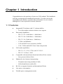
Chapter 1 Introduction
Congratulations on the purchase of your new 56K modem! This handbook
will help you through the installation procedure. You also can use the
commands in this book to customize the performance of your modem,
although this is not required for normal operation.
1.1 Features
!
Integrated PCI solution with 5 V tolerant buffers
!
!
!
Data mode capabilities:
ITU-T V.92 : 56000 bits/s—48000 bits/s
ITU-T V.90 : 56000 bits/s—28000 bits/s
ITU-T V.34: 33600 bits/s—2400 bits/s
V.32bis, and fallbacks
V.42 and MNP error correction (LAPM)
V.44, V.42bis and MNP Class 5 data compression
FAX mode capabilities:
ITU-T V.17, V.29, V.27ter, and V.21 Ch 2
ITU-T T.31 Class 1 FAX
Compatible with transformer-based and silicon DAA circuits:
!
Two chip modem solution without voice support
Line-powered silicon DAA
Enhanced voice features incorporating:
Telephone answering machine (TAM)
Caller identification (caller-ID)
!
Bit I/Os to support domestic and international DAAs
!
Low power consumption
!
Flexible power management modes
1
PCI Modem Card User's Manual
1.2 System Requirements
!
Pentium® III or above
!
Windows 95®/ 98®/ Me®/ NT4.0®/ 2000® / XP® operating system
!
One available PCI slot
!
32 MB RAM or more
!
CD-ROM drive
1.3 Package Contents
Your PCI modem package must include the following items:
2
!
PCI Modem Card
!
Software Utility/Driver CD
!
Quick Installation
Chapter 2 Hardware Installation
2.1 Installing the Card
Step1
With the power to your computer disconnected, remove PC casing.
Note: Some PCI compliant motherboards supply power to the slots
even when the PC is turned off. To prevent damage to your PC or
PCI modem card, always unplug the power cord when installing or
removing PCI modem cards.
Step 2
Press the PCI card into the empty PCI slot firmly, and secure it
with screws to your computer.
Step 3
Reinstall the casing on your computer.
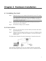
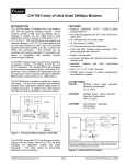
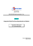
2.2 Connection
Step 1
Plug one end of the phone cord into LINE jack and the other end to
the wall phone jack.
Step 2
When you are not using the modem, you can use a telephone on the
modem’s phone line. Plug your telephone’s cord into the modem’s
PHONE jack.
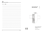
The figure below illustrates the typical connection of internal modem card.
After hardware installation, turn on your computer and the system should
detect the modem upon startup. Proceed to next section to install the drivers.
3
Chapter 3 Software Installation
Note: The document was written for both voice and non-voice model, so
some strings in the figures appearing during installation might be a little
different (but similar) from yours.
3.1 For Windows 95
Start Windows 95 and insert the provided CD into your CD-ROM drive to
start driver installation.
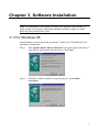
Step 1
The Update Device Driver Wizard screen will appear detecting a
new device and request for the driver. Click Next.
Step 2
Windows will be unable to locate the driver; click Other
Locations.
5
PCI Modem Card User's Manual
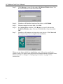
Step 3
Click Browse to specify the path to X:\Driver\Win9x where X is
the CD-ROM drive letter and click OK.
Step 4
Windows will find the location of the driver; click Finish.
Step 5
When prompted to insert disk, click OK.
Step 6
In Copying Files window, click Browse to specify the path to
X:\Driver\Win9x where X is the CD-ROM drive letter and click
OK.
Step 7
Windows will continue to detect the voice device. Click Next and
then repeat steps 2-4 to complete the installation.
When you are done with driver installation, you will need to specify the
country where you locate upon different telecommunication regulations/laws.
Please proceed to “Chapter 4 Configuring Countries” on page 15 for
instructions.
6
Chapter 3 Software Installation
3.2 For Windows 98
Start Windows 98 and insert the provided CD into your CD-ROM drive to
start driver installation.
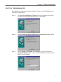
Step 1
The Add New Hardware Wizard screen will appear detecting a
new device and request for the driver. Click Next.
Step 2
Select Search for the best driver for you device and click Next.
Step 3
Check Specify a location, click Browse to specify the path to
X:\Driver\Win9x where X is your CD-ROM drive letter and click
OK. Then click Next.
7
PCI Modem Card User's Manual
Step 4
Windows will find the location of the driver; click Next.
Step 5
Click Finish.
Step 6
Windows will continue to detect the voice device. Click Next and
then repeat steps 2-5 to complete the installation.
When you are done with driver installation, you will need to specify the
country where you locate upon different telecommunication regulations/ laws.
Please proceed to “Chapter 4 Configuring Countries” on page 15 for
instructions.
3.3 For Windows Me
Start Windows Me and the system will auto-process the installation.
However, you need to update the driver by following the steps below.
8
Step 1
Click Start menu and then click Run. Click Browse to open the
file Setup.exe from X:\Driver\WinME where X is your CD-ROM
drive letter and click OK.
Step 2
When confirm message appears, click OK.
Chapter 3 Software Installation
Step 3
Wait for the system to complete updating the hardware information.
When you are done with driver installation, you will need to specify the
country where you locate upon different telecommunication regulations/ laws.
Please proceed to “Chapter 4 Configuring Countries” on page 15 for
instructions.
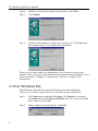
3.4 For Windows NT4.0
Step 1
Click Start menu and then click Run. Click Browse to open the
file Setup.exe from X:\Driver\NT40 where X is your CD-ROM
drive letter and click OK.
Step 2
When confirm message appears, click OK.
Step 3
When prompted to restart your computer, click OK.
When you are done with driver installation, you will need to specify the
country where you locate upon different telecommunication regulations/ laws.
Please proceed to “Chapter 4 Configuring Countries” on page 15 for
instructions.
9
PCI Modem Card User's Manual
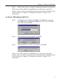
3.5 For Windows 2000
Start Windows 2000 and insert the provided CD into your CD-ROM drive to
start driver installation.
10
Step 1
The Found New Hardware Wizard screen will appear detecting a
new device and request for the driver. Click Next.
Step 2
Select Search for a suitable driver for my device and click Next.
Step 3
Check only Specify a location, and click Next.
Chapter 3 Software Installation
Step 4
Click Browse to locate the driver X:\Driver\W2K from your CDROM drive where X is your CD-ROM drive letter and click OK.
Step 5
Windows will find the location of the driver; click Next.
Step 6
If Digital Signature Not Found window appears, click Yes to
continue.
Step 7
Click Finish and wait for Windows to complete the installation.
When you are done with driver installation, you will need to specify the
country where you locate upon different telecommunication regulations/ laws.
Please proceed to “Chapter 4 Configuring Countries” on page 15 for
instructions.
11
PCI Modem Card User's Manual
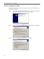
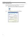
3.6 For Windows XP
The system will auto-process the driver installation for your modem card.
After that, follow the steps below to update its driver.
12
Step 1
Click Start menu, point to Settings and then click on Control
Panel. On the Control Panel, double-click the System icon.
Step 2
Click Hardware tab and then click Device Manager.
Chapter 3 Software Installation
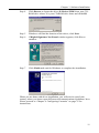
Step 3
Double-click Modems and right-click Lucent Win Modem. Select
Update Driver… from the context menu.
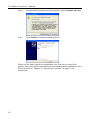
Step 4
When Hardware Update Wizard screen appears, select Install
from a list or specific location (Advanced) and click Next.
Step 5
With Search for the best driver… selected, check ONLY Include
this location in the search. Click Browse to locate the driver path
from X:\Driver\WinXP in your CD-ROM drive where X is your
CD-ROM drive letter and click Next.
13
PCI Modem Card User's Manual
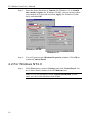
Step 6
If compatibility prompt message appears, click Continue Anyway.
Step 7
Click Finish to complete updating driver.
When you are done with driver installation, you will need to specify the
country where you locate upon different telecommunication regulations/ laws.
Please proceed to “Chapter 4 Configuring Countries” on page 15 for
instructions.
14
Chapter 4 Configuring Countries
Before using the modem, you may need to specify the country where you
locate upon different telecommunication regulations/ laws. If you have
configured your country during the installation process, just ignore this
section.
4.1 For Windows 95/98/Me
Note: If you are prompted with Location Information screen during
configuration, enter your area code and then click Close or OK.
Step 1
Click Start menu, point to Settings and click Control Panel. On
the Control Panel, double-click the Modems icon.
Step 2
In Modems Properties window, highlight Lucent Win Modem
and click Dialing Properties.
15
PCI Modem Card User's Manual
Step 3
From the drop-down list of I am in (for Windows 95) or I am in
this country/region (for Windows 98/Me), select a country where
your modem is to be used and click Apply (for Windows 98/Me
only) and then OK.
Windows 98/Me
Windows 95
Step 4
You will return to the Modems Properties window. Click OK to
return to Control Panel.
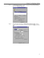
4.2 For Windows NT4.0
Step 1
Click Start menu, point to Settings and click Control Panel. On
the Control Panel, double-click the Modems icon.
Note: If you are prompted with Location Information screen,
enter your area code and then click Close.
16
Chapter 4 Configuring Countries
Step 2
In Modems Properties window, highlight Lucent Win Modem
and click Dialing Properties.
Step 3
From the drop-down list of I am in this country/region, select a
country where your modem is to be used and click Apply and then
OK.
17
PCI Modem Card User's Manual
4.3 For Windows 2000/XP
Note: The configuration steps are the same in Windows 2000 and Windows
XP. The graphics here assume a Windows 2000 environment.
Step 1
Click Start menu, point to Settings and click on Control Panel.
On the Control Panel, double-click the Phone and Modem
Options icon.
Note: If you are prompted with Location Information screen,
enter your area code and then click OK.
Step 2
18
On the Dialing Rules tab, select the location from which you are
dialing and then click Edit.
Chapter 4 Configuring Countries
Step 3:
On the General tab, from the drop-down list of Country/region
select the country where your modem is to be used. Click Apply
and then click OK.
19
Chapter 5 Verify Modem Installation
If you are going to install data/fax communications software, you may start
with a quick test to check that the Windows can communicate with your
modem.
5.1 For Windows 95/98/Me
Step 1
Click Start menu, point to Settings and then click Control Panel.
Double-click the Modems icon.
Step 2
Click the Diagnostics tab.
21
PCI Modem Card User's Manual
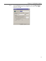
Step 3
Highlight the COM port used by your modem and then click More
Info….
Step 4
Wait for communication with your modem.
Step 5
If your modem is properly installed, the command response
(something like AT…) should appear on the screen.
Congratulations! You have successfully installed the modem
hardware and its driver.
* According to your model, the command responses may
differ from shown above.
Note: If your modem fails to respond, you will see an error
message. Make sure your modem is properly connected. Switch
your modem off and on, and try again. If your modem still fails to
respond, you may need to remove the driver and reinstall again.
22
Chapter 5 Verify Modem Installation
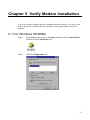
5.2 For Windows 2000/XP
Note: The verification steps are the same in Windows 2000 and Windows
XP. The graphics here assume a Windows 2000 environment.
Step 1
Click Start menu, point to Settings and then click Control Panel.
Double-click the Phone and Modem Options icon.
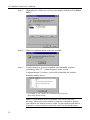
Step 2
In the Phone And Modem Options window, click the Modems
tab. Highlight Lucent Win Modem and then click Properties.
Step 3
Click the Diagnostics tab and then click Query Modem.
23
PCI Modem Card User's Manual
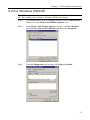
Step 4
Wait for communication with your modem.
Step 5
If your modem is properly installed, the command response
(something like AT…) should appear on the screen.
Congratulations! You have successfully installed the modem
hardware and its driver.
Note: If your modem fails to respond, you will see an error
message. Make sure your modem is properly connected. Switch
your modem off and on, and try again. If your modem still fails to
respond, you may need to remove the driver and reinstall again.
24
Chapter 6 Uninstalling the Drivers
This chapter describes how to uninstall the modem software from your
system. If you are going to uninstall the modem device permanently, follow
these steps:
1.
2.
3.
Uninstall the software first as described in this chapter.
Shut down your PC. Power off the PC and unplug all the peripherals.
Remove the cover and pull the modem card out of its PCI slot.
Then reinstall the cover and the peripherals.
It is also possible that you want to reinstall or upgrade the driver. If this is the
case, uninstall the modem software as described in this chapter and restart
your PC. Then refer to the installation instructions to install required driver.
6.1 For Windows 95
Step 1
Click Start menu, point to Settings and then click Control Panel.
Double-click the Modems icon.
Step 2
On the General tab, highlight Lucent Win Modem and then click
Remove.
Step 3
You will find the modem has been removed from the modem list.
Click Close to return to the Control Panel.
25
PCI Modem Card User's Manual
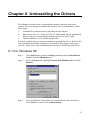
6.2 For Windows 98/Me/NT4.0/2000/XP
Note: For Windows 98/Me/NT4.0/2000/XP users, please have the provided
CD handy before you perform remove procedures.
26
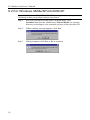
Step 1
Insert the provided CD into your CD-ROM drive. Run
Ltremove.exe from the subdirectory \Driver\Win9x (or relevant
directory according to your operation system) of the provided CD.
Step 2
When warning message appears, click Yes.
Step 3
When prompted, click Yes or No as required.
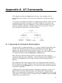
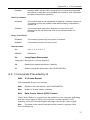
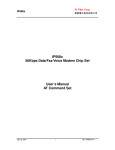
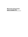
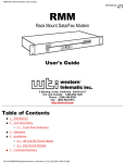
Appendix A AT Commands
This chapter provides an alphabetized reference with examples for all
commands for the modem. The system of commands is depicted in figure
below.
To use these commands for dialing or configuring the modem, make sure the
communications software package you will be using lets you operate the
modem through its interna1 commands. If your software permits use of the
modem's internal commands, read this chapter. If not, read your software
user's manual and ignore the rest of this manual.
A.1 General Command Information
Except for the A/ command and the + + + escape command described in this
manual, all commands must be prefixed with the attention code AT. For
instance, the A command (below) would be entered as: "AT A <CR>".
Without the AT prefix, the command line cannot be executed. Once entered,
AT cannot be deleted with the Backspace or Delete keys.
More than one command can be placed on a single line and, if desired,
separated with spaces for readability. Once the carriage return (Enter) key is
pressed, the command line is executed. A line with no carriage return is
ignored.
The modem accepts either upper or lower case characters in the command
line and ignores any spaces within or between commands. Typing errors can
be corrected with the Backspace key. Exceptions are noted in the description
of specific commands.
Variables (r and x) are listed in italics. Punctuation symbols (, ; ! @) use as
dial modifiers are listed alphabetically according to their English names.
Where two commands are separated by a slash, either command will have the
same effect. For example, if the command is listed as B0/B, issuing either B0
or B will have the same effect.
27
PCI Modem Card User's Manual
A.2 AT Commands
A
Go On-line in Answer Mode
This command instructs the modem to go off-hook immediately and then
make a handshake with the remote modem. Handshaking is not available
during leased line operation.
A is usually used to manually answer an incoming call or to switch from
voice conversation to data communication.
Bn
Communication Standard Setting
This command determines ITU-T vs. Bell standard.
B0
Selects ITU-T V.22 mode when the modem is at 1200 bits/s.
B1
Selects Bell 212A when the modem is at 1200 bits/s. (default)
B2
Unselects V.23 reverse channel (same as B3).
B3
Unselects V.23 reverse channel (same as B2).
B15
Selects V.21 when the modem is at 300 bits/s.
B16
Selects Bell 103J when the modem is at 300 bits/s. (default)
Cn
Carrier Control Option(dummy command)
This command is used by some modems to control the transmit carrier. This
chip set does not support C0 and will respond in error if this command is
given. This chip set will accept C1 without error in order to ensure backward
compatibility with communications software that issues this command.
C0
Transmit carrier always off (returns ERROR).
C1
Normal transmit carrier switching. (default)
Dn
Dial
This command instructs the modem to begin the dialing sequence. The dial
string (n, including modifiers and the telephone number) is entered after the
ATD command.
A dial string can be up to 40 characters long. Any digit or symbol (0-9, *, A,
B, C, D) may be dialed as touch tone digits. Characters such as spaces,
hyphens, and parentheses do not count-they are ignored by the modem and
may be included in the dial string to enhance readability.
The following may be used as dial string modifiers:
28
Appendix A AT Commands
L
Redials last number. Should be the first character following ATD,
ignored otherwise.
P
Pulse dialing.
T
Touch-tone dialing. (default)
,
Pause during dialing. Pause for time specified in Register S8
before processing the next character in the dial string.
W
Wait for dial tone. Modem waits for a second dial tone before
processing the dial string.
V
The modem switches to speakerphone mode and dials the
number. An ATH command may be used to disconnect the voice call.
@
Wait for quiet answer. Wait for five seconds of silence after
dialing the number. If silence is not detected, the modem sends a NO
ANSWER result code back to the user.
!
Hook flash. Causes the modem to go on-hook for 0.5 seconds
and then return to off-hook.
;
Return to command mode. Causes the modem to return to
command mode after dialing the number, without disconnecting the call.
^
Disable data calling tone transmission.
S=n
Dial a telephone number previously stored. The range of n is 0-3.
$
Bong tone detection.
En
AT Command Echo Options
This command determines whether characters are echoed to the DTE from
the modem when it is in command state.
E0
Echo disabled.
E1
Echo enabled. (default)
Fn
On-Line Data Character Echo Command
This command determines if the modem will echo data from the DTE. This
modem does not support the F0 version of the command. However, the
modem will accept F1, which may be issued by older communication
software, to assure backward compatibility.
F0
On-line data character echo enabled (NOT SUPPORTED, ERROR).
F1
On-line data character echo disabled.
Hn
Hook Control
29
PCI Modem Card User's Manual
This command instructs the modem to go on-hook to disconnect a call, or
off-hook to make the phone line busy.
H0
Modem goes on-hook. (default)
H1
Modem goes off-hook.
In
Request ID Information
This command displays specific product information about the modem.
I0
I3)
Returns default speed and controller resource version. (same as
I1
Calculates ROM checksum and displays it on the DTE.
I2
Performs a ROM check and calculates and verifies the checksum
displaying OK or ERROR.
I3
Returns the default speed and the controller resource version.
(same as I0)
I4
Returns resource version for data pump.
I9
Returns country code.
Ln
Speaker Volume
This command determines the volume level of the speaker, when supported
by the modem.
L0
Lowest speaker volume.
L1
Low speaker volume.
L2
Medium speaker volume. (default)
L3
High speaker volume.
Mn
Speaker Control
This command determines whether the speaker function of the modem is on
or off.
30
M0
Speaker always off.
M1
Speaker on until carrier present. (default)
M2
Speaker always on.
M3
Speaker off during dialing and on until carrier.
Nn
Modulation Handshake
Appendix A AT Commands
This command controls whether or not the local modem performs a
negotiated handshake at connection time with the remote modem when the
communication speed of the two modems is different.
N0
When originating or answering, this is for handshake only at the
communication standard by S37 and the ATB command.
N1
When originating or answering, begin the handshake only at the
communication standard specified by S37 and the ATB command. During
handshake, fallback to a lower speed may occur. (default)
On
Return On-Line to Data Mode
O0
Instructs the modem to exit on-line command mode and return to
data mode (see AT Escape Sequence, +++).
O1
line data mode.
This command issues a retrain before returning to on-
O3
This command issues a rate renegotiation before returning to online data mode.
P
Enable Pulse Dialing
This command instructs the modem to use pulse dialing. Dialed digits will be
pulsed dialed until a T command or dial modifier is received. Tone dial is the
default setting.
Qn
Results Code Display Option
This command controls whether the result codes are displayed to the DTE.
Q0
Result codes enabled. (default)
Q1
Result codes disabled.
Sn
Selects an S Register
This command selects a specific S register. n = 0 - 99
Sn=m Writes to an S Register
This command writes a value to a specified register.
n = 0 - 99
m = 0 - 255
Sn? Reads an S Register
This command display the value of a specified register in decimal form.
n=0 - 99
31
PCI Modem Card User's Manual
T
Enable Tone Dialing
This command instructs the modem to send DTMF tones while dialing.
Dialed digits will be tone dialed until a P command or dial modifier is
received. This is the default setting.
Vn
Result Code Form
This command controls whether result codes (including call progress and
negotiation progress message) are displayed as words or their numeric
equivalents.
V0
Displays result codes as digits.
V1
Displays result codes as text. (default)
Wn
Select Extended Result Codes
This command determines which result codes will be used to describe the
type of connection and protocol that resulted from handshaking and
negotiation.
W0
CONNECT result code reports DTE speed. (default)
W1
CONNECT result code reports DTE speed; enable the CARRIER,
COMPRESSION and PROTOCOL extended result code.
W2
CONNECT result code reports DCE speed.
Xn
Result Codes Selection and Call Progress Monitoring
This command enables tone detection options used in the dialing process. As
these functions are chosen, the modem chip set's result codes are also
affected. Therefore, this command is frequently used to control the modem
chip set's responses. The primary function of this control is to control the
modem chip set's call response capabilities.
Command
Ext. Result Code
Dial Tone Detect
Busy Tone Detect
X0
X1
X2
X3
X4
X5
X6
X7
Disable
Enable
Enable
Enable
Enable
Enable
Enable
Disable
Disable
Disable
Enable
Disable
Enable
Enable
Enable
Enable
Disable
Disable
Disable
Enable
Enable(default)
Enable
Enable
Enable
Extended Result Codes
Disabled:
32
Displays only the basic result codes OK, CONNECT, RING, NO
CARRIER, and ERROR.
Appendix A AT Commands
Enabled:
Displays basic result codes, along with the connect message and
the modem's data rate, and indicates the modem's error correction
and data compression operation.
Dial Tone Detect
Disabled:
The modem dials a call regardless of whether it detects a dial tone.
The period of time the modem waits before dialing is specified in
register S6.
Enabled:
The modem dials only upon detection of a dial tone, and
disconnects the call if the dial tone is not detected within 10
seconds.
Busy Tone Detect
Disabled:
The modem ignores any busy tones it receives.
Enabled:
The modem monitors for busy tones.
Result Codes:
OK
n=0, 1, 2, 3, 4, 5, 6, 7
ERROR
Otherwise.
Yn
Long Space Disconnect
Long space disconnect is always disabled.
Y0
Disable long space disconnect. (default)
Y1
Enable long space disconnect. NOT SUPPORTED.
A.2.1 Commands Preceded by &
&Bn
V.32 Auto Retrain
This command always auto retrains.
&B0
Disable V.32 auto retrains - NOT SUPPORTED.
&B1
Enable V.32 auto retrain. (default)
&Cn
Data Carrier Detect (DCD) Control
Data Carrier Detect is a signal from the modem to your computer indicating
that the carrier signal is being received from a remote modem. DCD
normally turns off when the modem no longer detects the carrier signal.
&C0
The state of the carrier from the remote modem is ignored. DCD
circuit is always on.
33
PCI Modem Card User's Manual
&C1
DCD turns on when the remote modem's carrier signal is
detected, and off when the carrier signal is not detected. (default)
&Dn
DTR Control
This command interprets how the modem responds to the state of the DTR
signal and changes to the DTR signal.
&D0
Ignore. The modem ignores the true status of DTR and treats it
as always on. This should only be used if your computer does not provide
DTR to the modem.
&D1
If the DTR signal is not detected while in on-line data mode, the
modem enters command mode, issues OK result code, and remains
connected.
&D2
If the DTR signal is not detected while in on-line data mode, the
modem disconnects. (default)
&D3
Reset on on-to-off DTR transition.
&F
Load Factory Settings
This command loads the configuration stored and programmed at the factory.
This operation replaces all of the command options and S register settings in
the active configuration with factory values stored in the nonvolatile RAM.
&F
Recall factory setting as active configuration.
&Gn
Guard Tone Option
This command determines which guard tone, if any, to transmit while
transmitting in the high band (answer mode). This command is only used in
V.22 and V.22bis mode.
&G0
No guard tones. (default)
&G1
550 Hz guard tone.
&G2
1800 Hz guard tone.
&Jn
Auxiliary Relay Option
&J0
The auxiliary relay is never closed.
&J1
NOT SUPPORT, responds ERROR.
&Kn
Select Flow Control
This command selects the flow control method the modem chip set provides
to the DTE to prevent the modem's buffer from overflowing with data. A
data buffer holds the data until the modem is ready to transmit it. When the
34
Appendix A AT Commands
data buffer is full, flow control instructs the DTE to stop sending to the
modem while the modem continues to send characters.
&K0
Disable flow control.
&K1
Reserved.
&K2
Reserved.
&K3
Enable bi-directional hardware flow control (RTS/CTS). (default)
&K4
Enable bi-directional XON/XOFF flow control.
&Mn
Asynchronous Communications Mode
&M0
Asynchronous mode. (default)
&M1
Reserved.
&M2
Reserved.
&M3
Reserved.
&M4
Reserved.
&Qn
Asynchronous Communications Mode
&Q0
Asynchronous Mode, buffered. (Same as \N0)
&Q5
Error Control Mode, buffered. (default)(Same as \N3)
&Q6
Asynchronous Mode, buffered. (Same as \N0)
&Q8
MNP error control mode. If an MNP error control protocol is not
established, the modem will fallback according to the current user setting
in S36.
&Q9
V.42 or MNP error control mode. If neither error control protocol is
established, the modem will fallback according to the current user setting
in S36.
Result Codes:
OK
n=0, 5, 6, 8, 9
&Sn
Data Set Ready Option
This command controls the functions of DSR. DSR indicates when the
modem is connected to a communications channel and is ready. Async mode
only. If the modem is in Sync mode, DSR is on during handshake and on-line,
off in test or idle mode.
&S0
DSR circuit always on. (default)
35
PCI Modem Card User's Manual
&S1
DSR circuit on during handshaking and on-line, off in test modes
or in idle mode.
Result Codes:
OK
n=0, 1
&Tn
Self-Test Commands
These commands allows the user to perform diagnostic tests on the modem.
Thses tests can help to isolate problems when experiencing periodic data loss
or random errors.
&T0
Abort. Stops any test in progress.
&T1
Local analog loop. This test verifies modem operation, as well as
the connection between the modem and computer. Any data entered at
the local DTE is modulated, then demodulated, and returned to the local
DTE. To work properly, the modem must be off-line.
&Vn
View Active Configuration and Stored Profile
This command is used to display the active profiles.
&V0
&Wn
View active file.
Store Current Configuration
This command stores certain command options and S-register values into the
modem's nonvolatile memory. The ATZ command or a power-up reset of the
modem restores this profile.
A.2.2 Commands Preceded by \
\Gn
Modem Port Flow Control
\G0
Returns an "OK" for compatibility. (default)
Result Codes:
OK
n=0
ERROR Otherwise.
\Jn
Adjust Bits/s Rate Control
When this feature is enabled, the modem emulates the behavior of modems
that force the DTE interface to the line speed.
36
\J0
Turn off feature. (default)
\J1
Turn off feature.
Appendix A AT Commands
\Kn
Set Break Control
This command determines how the modem processes a Break signal received
from the local DTE during a connection(online).
\K0
Reserved, returns ERROR.
\K1
Reserved, returns ERROR.
\K2
Reserved, returns ERROR.
\K3
Reserved, returns ERROR.
\K4
Reserved, returns ERROR.
\K5
Modem sends the break to the remote modem in sequence with
0the transmitted data, non-destructive/non-expedited. (default)
\Nn
Error Control Mode Selection
This command determines the type of error control used by the modem when
sending or receiving data.
\N0
Buffer mode. No error control. (Same as &Q6)
\N1
Direct mode.
\N2
MNP or disconnect mode. The modem attempts to connect using
MNP 2-4 error control procedures. If this fails, the modem disconnects.
This is also known as MNP reliable mode.
\N3
V.42, MNP, or buffer. The modem attempts to connect in V.42
error control mode. If this fails, the modem attempts to connect in MNP
mode. If this fails, the modem connects in buffer mode and continues
operation. This is also known as V.42/MNP auto reliable mode. (Same as
&Q5) (default)
\N4
V.42 or disconnect. The modem attempts to connect in V.42
error control mode. If this fails, the call will be disconnected.
\N5
V.42, MNP or buffer. (Same as \N3)
\N7
V.42, MNP or buffer. (Same as \N3)
\Qn
Local Flow Control Selection
\Q0
Disables flow control. (Same as &K0)
\Q1
XON/XOFF software flow control. (Same as &K4)
\Q2
CTS-only flow control. This is not supported and the response is
ERROR.
\Q3
RTS/CTS to DTE. (Same as &K3) (default)
37
PCI Modem Card User's Manual
\Tn
Inactivity Timer
This command specifies the length of time (in minutes) that the modem will
wait before disconnecting when no data is sent or received. A setting of zero
disables the timer. Alternatively, this timer may be specified in register S30.
This function is only applicable to buffer mode.
\Vn
Protocol Result Code
\V0
Disable protocol result code appended to DCE speed.
\V1
Enable protocol result code appended to DCE speed. (default)
A.2.3 Commands Preceded by %
%Cn
Data Compression
This command controls the MNP Class 5. The command can only perform
data compression on an error corrected link.
%C0
No compression.
%C1
MNP Class 5 compression. (default)
Result Codes:
OK
n=0, 1
A.2.4 Commands Preceded by -Cn
Data Calling Tone
Data Calling Tone is a tone of certain frequency and cadence as specified in
V.25 which allows remote Data/FAX/Voice discrimination. The frequency is
1300 Hz with a cadence of 0.5 s on and 2 s off.
-C0
Disabled. (default)
-C1
Enabled.
A.2.5 Commands Preceded by "
"Hn
V.42bis Compression Control
This command controls V.42bis data compression over an error correction
link.
"H0
38
Disable V.42bis.
Appendix A AT Commands
"H1
Enable V.42bis only when transmitting data.
Result Codes:
OK
n=0, 1
A.3 Commands Not Preceded By AT
Two commands, A/ and +++, are neither preceded by the attention code AT
nor followed by a carriage return.
A/
Repeat Command
A/ repeats the execution of the last command line stored in the command
buffer. If the last command line is invalid, the ERROR result code will
appear on the screen. Note that A/ cannot be preceded by AT; if it is,
ERROR will appear on the screen.
+++
Escape
+++ followed by AT<CR> returns to the on-line command state (command
state without breaking the established connection) from the on-line state.
To escape, stop transmitting data, wait at least one escape guard time (the
default time is one second), and then enter three consecutive escape
characters (the default character is +) followed by AT<CR>. After one more
escape guard time (one second), the modem returns to the command state and
sends the OK result code to the screen. Note that the escape command is the
only command that can be recognized by the modem in the on-line state; it
cannot be recognized in the command state.
39
Appendix B S Register Reference
Your modem has status registers. These registers are memory locations
inside your modem which control your modem's operation. You usually do
not have to worry about setting any register because the default values work
for most applications.
Registers denoted with an "*" may be stored in one of the two user profiles
by entering the &Wn command.
The factory default values are stored in ROM and are loaded into the active
configuration at power-up. In addition, the designated default profile is
subsequently loaded, and may change some of the factory default values. The
designated default profile can be changed by entering the &Yn command,
where 'n' is one of the two possible user profiles. The factory defaults can be
loaded at any time by entering the &F command.
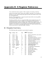
B.1 Register Summary
The following chart summarizes your modem's registers:
Reg.#
Range
Unit
S0
S1
S2
S3
S4
S5
S6
S7
S8
S10
S11
S12
S28
S30
S32
S33
S35
S36
S37
S42
S43
0-255
ring
0-255
ring
0-255
ASCII
0-127
ASCII
0-127
ASCII
0-32,127 ASCII
2-65
seconds
1-255
seconds
0-65
seconds
1-254
1/10 sec.
50-150 1/1000 sec.
0-255
1/50 sec.
0-255
0-255
minutes.
dB
0-5
0-1
0-7
0-19
0-1
0-1
Dec
Default
Hex
Description
0
0
43
13
10
8
2
50
2
20
95
50
1
0
10
0
0
7
0
1
1
00h
00h
2Bh
0Dh
0Ah
08h
02h
32h
02h
14h
5Fh
32h
01h
00h
10h
00h
00h
07h
00h
01h
01h
Number of Ring Before Auto-answer.
Ring Count.
AT Escape Character.
Command Line Termination Character.
Response Formatting Character.
Command Line Editing Character.
Wait Before Dialing.
Connection Completion Time-Out.
Comma Dial Modifier Time.
Automatic Disconnect Delay.
DTMF Dialing Speed.
Escape Guard Time.
V.34 Modulation Enable/Disable.
Inactivity Timer.
Synthetic Ring Volume.
Synthetic Ring Frequency.
Data Calling Tone.
Negotiation Fallback.
Dial Line Rate.
Auto Rate.
Auto Mode.
41
PCI Modem Card User's Manual
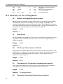
S48
7, 128
7
07h
S89
S90
S91
0, 5-255
0-1
6-15
1dB
10
0
10
0Ah
00h
0Ah
LAPM Error Control and Feature
Negotiation.
Timer to Control Sleep Mode.
Local Phone Status.
Line Transmit Level.
B.2 Glossary of the S Registers
S0
Number of Rings Before Auto Answer
S0 determines the number of rings that must be received before the modem
automatically answers an incoming call. For example, when S0=3, the
modem automatically answers after the third ring. When S0=0, the modem
does not automatically answer an incoming call; it stays on-hook until the A
command is issued manually to answer the incoming call.
Range:
0-255
Default:
0
S1
Ring Count
S1 automatically increments its value by one each time the modem receives a
ring while in the command state. S1 is reset to zero if no ring is detected
within 8 seconds.
Range:
0-255
Default: 0
S2
AT Escape Character(user defined)
This register determines the ASCII valued used for an escape sequence. The
default is the + character. The escape sequence allows the modem to exit data
mode and enter command mode when on-line. Values greater than 127
disable the escape sequence.
Range:
0-255
Default:
43(+)
S3
Command Line Termination Character(user defined)
This register determines the ASCII values as the carriage retuen character.
This character is used to end command lines and result codes.
Range:
0-127
Default:
13(carriage return)
S4
42
Response Formatting Character(user defined)
Appendix B S Register Reference
This register determines the ASCII value used as the line feed character. The
modem uses a line feed character in command mode when it responds to the
computer.
Range:
0-127
Default:
10(Line Feed)
S5
Command Line Editing Character (user defined)
This register sets the character recognized as a backspace and pertains to
asynchronous only. The modem will not recognize the backspace character if
it is set to a value that is greater than 32 ASCII. This character can be used to
edit a command line. When the echo command is enabled, the modem echoes
back to the local DTE the backspace character, an ASCII space character,
and a second backspace character. This means a total of three characters are
transmitted each time the modem processes the backspace character.
Range:
0-32, 127
Default:
8(backspace)
S6
Wait Before Dialing
This register sets the length of time, in seconds, that the modem must wait
(pause) after going off-hook before dialing the first digit of the telephone
number. The modem always pauses for a minimum of 2 seconds, even if the
value of S6 is less than two seconds. If wait for dial tone call progress feature
(W dial modifier in the dial string) will override the value in register S6. This
operation, however, may be affected by some ATX options according to
country restrictions.
Range:
2-65
Default:
2
S7
Connection Completion Time-Out
This register sets the time, in seconds, that the modem must wait before
hanging up because carrier is not detected. The timer is started when the
modem finishes dialing (originate), or goes off-hook (answer). In originate
mode, the timer is reset upon detection of an answer tone if allowed by
country restriction. The timer also specifies the wait for silence time for the
@ dial modifier in seconds. S7 is not associated with the W dial modifier.
Range:
1-255
Default:
50
S8
Comma Dial Modifier Time
43
PCI Modem Card User's Manual
This register sets the time, in seconds, that the modem must pause when it
encounters a comma(,) in the dial command string.
Range:
0-65
Default:
2
S10
Automatic Disconnect Delay
This register sets the length of time, in tenths of a second, that the modem
waits before hanging up after a loss of carrier. This allows for a temporary
carrier loss without causing the local modem to disconnect.
The actual interval the modem waits before disconnecting is the value in
register S10.
Range:
1-254
Default:
20
S11
DTMF Dialing Speed
This register determines the dialing speed which is prefixed for each country.
Range:
50-150
Default:
95
S12
Escape Guard Time
This register determines the escape guard time. The escape guard time is the
minimum waiting time required before and after entering the escape code
(three consecutive escape characters) in the on-line state. It is also the
maximum waiting time allowed between any two consecutive escape
characters. If the waiting time before or after the escape code is shorter than
the guard time, or if the waiting time between consecutive escape characters
is longer than the guard time, then the modem does not recognize the escape
command and stays on-line.
If the escape guard time is set at 0 seconds, it is impossible to return the
modem to command state.
Range:
0-255
Default:
50
S28
V.34 Modulation Enable/Disable
This register enables/disables V.34 modulation.
0
44
Disabled.
Appendix B S Register Reference
1-255
Enabled.
Range:
0-255
Default:
1
S30
Inactivity Timer
This register specifies the length of time, in minutes, that the modem will
wait before disconnection when no data is sent or received. This function is
only applicable to buffer mode.
Range:
0-255
Default:
0
S32
Synthetic Ring Volume
This register specifies a synthetic ring volume in dB with an implied minus
sign.
Default:
S33
10
Synthetic Ring Frequency
This register specifies a synthetic ring frequency. Valid ranges are 0-5, with
0=disabled and 1-5 corresponding to 5 ring frequencies.
Range:
0-5
Default:
0
S35
Data Calling Tone
Data Calling Tone is a tone of certain frequency and cadence as specified in
V.25 which allows remote Data/FAX/Voice discrimination. The frequency is
1300 Hz with a cadence of 0.5 s on and 2 s off.
0
Disabled.
1
Enabled.
Range:
0-1
Default:
0
S36
Negotiation Fallback
This register specifies the action to take in the event of negotiation failure
when error control is selected.
0, 2
Hang up.
45
PCI Modem Card User's Manual
1, 3
Fall back to an asynchronous connection.
4, 6
Attempt MNP. If MNP fails, hang up.
5, 7
Attempt MNP. If MNP fails, fall back to asynchronous
connection.
Default:
S37
Dial Line Rate
0
Maximum modem speed.
1
Reserved.
2
1200/75 bits/s.
3
300 bits/s.
4
Reserved.
5
1200 bits/s.
6
2400 bits/s.
7
4800 bits/s.
8
7200 bits/s.
9
9600 bits/s.
10
12000 bits/s.
11
14400 bits/s.
12
16800 bits/s.
13
19200 bits/s.
14
21600 bits/s.
15
24000 bits/s.
16
26400 bits/s.
17
28800 bits/s.
18
31200 bits/s.
19
33600 bits/s.
Default:
46
7
0
Appendix B S Register Reference
S42
Auto Rate
This command is used for testing and debugging only.
V.32bis and V.22bis auto rate is disabled. Retrain operation is disabled or
enabled in data mode, and fallback is disabled in data mode.
0
Disabled.
1
Enabled.
Range:
0-1
Default:
1
S43
Auto Mode
This command is used for testing and debugging only.
V.32bis startup auto mode operation disabled.
0
Disabled.
1
Enabled.
Range:
0-1
Default:
1
S48
LAPM Error Control and Feature Negotiation
7
Negotiation enabled.
128
Negotiation disabled; forces immediate fallback options
specified is S36.
Default:
7
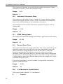
The following chart lists the S36 and S48 configuration settings necessary to
negotiate certain types of connections.
S48=7
S48=128
S36=0, 2
LAPM or hangup
do not use
S36=1, 3
LAPM or async
async
S36=4, 6
LAPM, MNP or hangup
MNP or hangup
S36=5, 7
LAPM, MNP or async
MNP or async
S89
Timer to Control Sleep Mode
47
PCI Modem Card User's Manual
This command displays the number of seconds of inactivity (no characters
sent from the DTE, no RING) in the off-line command state before the
modem places itself into standby mode. A value of zero prevents standby
mode.
Note: If a number between 1 and 4 is entered for this register, it will set the
value to 5, and the inactivity before standby will be 5 seconds. This is done
for compatibility with previous products which allowed time-outs down to 1
s.
Range:
0, 5-255
Default:
10
S90
Local Phone Status
This register tells the status of the Local Phone. It is read only.
0
Local phone on-hook.
1
Local phone off-hook.
Range:
0-1
Default:
0
S91
Line Transmit Level
This register is effective only for Japan. It specifies the line transmit level in
dB with an implied minus sign.
48
Range:
6-15
Default:
10
Appendix C Technical Specifications
Compatibility
ITU-T V.92 V.90
ITU-T V.34Annex12
ITU-T V.34
ITU-T V.32 bis
ITU-T V.32
ITU-T V.17
ITU-T V.29
ITU-T V.27 ter
ITU-T V.22 bis
ITU-T V.23
ITU-T V.22
ITU-T V.21
BELL 212A
BELL 103
56000, 54667, 53333, 52000, 50667, 49333,
48000, 46667, 45333, 42667, 41333, 40000,
38667, 37333, 36000, 34667,
33333, 32000, 30667, 29333, 28000 bps.
33600, 31200 bps.
28800, 26400, 24000, 21600, 19200, 16800,
14400, 12000, 9600, 7200, 4800 bps
14400, 12000, 9600, 7200, 4800 bps
9600, 4800 bps
14400bps/12000bps
9600bps/7200bps
4800bps/2400bps
2400bps
1200bps/75bps
1200bps
300bps
1200bps
300bps
Modulation
56000bps(ITU-T V.90)
33600bps(V.34Annex12)
31200bps(V.34Annex12)
28800bps(V.34/V.FC)
14400bps (V.32 bis)
12000bps (V.32 bis)
9600bps (V.32 bis)
7200bps (V.32 bis)
9600bps (V.32)
4800bps (V.32)
14400bps (V.17)
PCM
TCM
TCM
TCM
TCM
TCM
TCM
TCM
TCM,QAM
QAM
TCM
49
PCI Modem Card User's Manual
12000bps (V.17)
9600bps (V.29)
7200bps (V.29)
4800bps (V.27ter)
2400bps (V.27ter)
2400bps (V.22bis)
1200bps/75bps(V.23)
1200bps (V.22/Bell 212A)
300bps (V.21/Bell 103)
TCM
QAM
QAM
DPSK
DPSK
QAM
FSK
DPSK
FSK
Operation
!
Full-duplex or half duplex in Data mode.
!
Half-duplex in Fax mode.
!
Asynchronous operation.
!
Auto dial/answer.
!
Manual originate/answer.
!
Call waiting
!
Quick Connector
!
Quick Upload
TAM
Support telephone answer machine.
Plug and Play
Optional Plug and Play device.
Data mode
50
!
Ultrahigh compression throughput due to parallel access directly to the
host PC.
!
ITU-T V.34 extended rates 33600bps to 2400bps.
!
V.32terbo, V.32bis and fallbacks.
!
TIA/EIA 602 standard for AT command set.
!
V.42 error correction (LAMP and MNP).
!
V.42bis and MNP Class 5 data compression.
Appendix C Technical Specifications
Fax mode
Fax modem send and receive rates up to 14400bps
!
V.17, V.29, V.27ter, and V.21 channel 2.
!
TIA/EIA 578 Class1 FAX.
Asynchronous Data Format
Parity
Data Length
None
Odd
Even
None
Stop Bits
7
7
7
8
Character Length
2
1
1
1
10
10
10
10
Line Operating Speed
56000bps, 52000bps, 48000bps, 40000bps, 36000bps, 32000bps.(Receive
Only)
33600bps, 31200bps, 28800bps, 26400bps, 24000bps, 21600bps, 19200bps,
16800bps, 14400bps, 12000bps, 9600bps, 7200bps, 4800bps, 2400bps,
1200bps, 300bps.
Dialing Type
Tone or Pulse dialing.
Call Progress Monitors
Dial tone, Busy tone.
Diagnostics
!
Remote digital loop and remote digital loop self test.
!
Analog loop and analog loop self test.
!
Power-on self test
Flow Control
XON/XOFF or RTS/CTS
Telephone Line Interface
Single RJ-11 phone jack for PSTN line.
Receive Sensitivity
-33 ± 2 dBm
Transmit Sensitivity
-11± 2 dBm
51
PCI Modem Card User's Manual
DTMF SIGNAL LEVEL (dBm)
Hi. G = -8± 2 dBm
Lo. G = -10± 2 dBm
M/B RATIO
39± 3/61± 4
10 PPS
RETURN LOSS
300Hz ~ 3400Hz >10 dB
Carrier Frequency
!
V.34
1800Hz 0.01%
!
V.32bis
1800Hz 0.01%
!
V.32
1800Hz 0.01%
!
V.17
1800Hz 0.01%
!
V.29
1700Hz 0.01%
!
V.27ter
1800Hz 0.01%
!
V.22bis, original mode
1200Hz 0.01%
!
V.22bis, answer mode
2400Hz 0.01%
!
V.22, original mode
1200Hz 0.01%
!
V.22, answer mode
2400Hz 0.01%
!
V.21 channel #1, mark
980Hz 0.01%
!
V.21 channel #1, space
1180Hz 0.01%
!
V.21 channel #2, mark
1650Hz 0.01%
!
V.21 channel #2, space
1850Hz 0.01%
!
Bell 212A, original mode
1200Hz 0.01%
!
Bell 212A, answer mode
2400Hz 0.01%
!
Bell 103, original mark
1270Hz 0.01%
!
Bell 103, original space
1070Hz 0.01%
!
Bell 103, answer mark
2225Hz 0.01%
!
Bell 103, answer space
2025Hz 0.01%
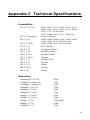
DTMF Tone Frequency
Low Group Frequency (Hz)
52
Appendix C Technical Specifications
High Group
Frequency (Hz)
1209
1336
1477
1633
697
1
2
3
A
770
4
5
6
B
852
7
8
9
C
941
*
0
#
D
*Specification and features subjects to change without notice.
53
Appendix D Quick Reference
A
Go On-line in Answer Mode
Bn
Communication Standard Setting
Cn
Carrier Control Option (dummy command)
Dn
Dial
En
AT Command Echo Options
Fn
On-Line Data Character Echo Command
Hn
Hook Control
In
Request ID Information
Ln
Speaker Volume
Mn
Speaker Control
Nn
Modulation Handshake
On
Return On-Line to Data Mode
P
Enable Pulse Dialing
Qn
Results Code Display Option
Sn
Selects an S Register
T
Enable Tone Dialing
Vn
Result Code Form
Wn
Select Extended Result Codes
Xn
Result Code Selection and Call Progress Monitoring
Yn
Long Space Disconnect
&Bn
V.32 Auto Retrain
&Cn
Data Carrier Detect (DCD) Control
&Dn
DTR Control
55
PCI Modem Card User's Manual
&F
Load Factory Settings
&Gn
Guard Tone Option
&Jn
Auxiliary Relay Option
&Kn
Select Flow Control
&Mn
Asynchronous Communications Mode
&Qn
Asynchronous Communications Mode
&Sn
Data Set Ready Option
&Tn
Self-Test Commands
&Vn
View Active Configuration and Stored Profile
&Wn Store Current Configuration
56
\Gn
Modem Port Flow Control
\Jn
Adjust Bits/s Rate Control
\Kn
Set Break Control
\Nn
Error Control Mode Selection
\Qn
Local Flow Control Selection
\Tn
Inactivity Timer
\Vn
Protocol Result Code
%Cn
Data Compression
-Cn
Data Calling Tone
"Hn
V.42bis Compression Control
A/
Repeat Command
+++
Escape
Appendix E Glossary
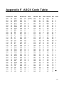
ASCII - An acronym for American Standard Code for Information
Exchange. ASCII is a seven-bit code which defines 128 standard characters,
including control characters, letters, numbers, and symbols. An extra 128
characters comprise the extended ASCII set.
Baud Rate - The transmission rate between two serial devices, e.g.,
modems, fax machines, etc. Measured in Bits Per Second.
Blind Dialing - In blind dialing, the modem continues to dial, regardless of
the existence of a dialtone, ring, or busy signal.
BPS - Bits Per Second; the number of bits that can be transmitted in one
second.
Carrier Signal - The analog data signal that a modem sends over telephone
wires.
COMx - Where (x = 1, 2, 3, or 4), COMx is the name(address) of serial
communications ports on personal computers. Each serial port in a personal
computer has a different number.
CTS -
Clear To Send.
Default - The assumed value that is used for a command parameter when
no other value is explicitly provided.
DCD - Data Carrier Detect.
DCE - Data Communication Equipment.
DTE - Data Terminal Equipment.
DSVD - Digital Simultaneous Voice and Data.
DTMF - Dual Tone Multifrequency(for touchtone dialing).
DTR - Data Terminal Ready.
FSK - Frequency Shift Keying.
GSTN - General Switched Telephone Network.
Make/Break Ratio - The ratio of the off-hook (make) to on-hook (break)
interval is the make/break ratio in pulse dialing.
57
PCI Modem Card User's Manual
Modem - A combination of the words MOdulator and DEModulator.
Modems transform digital data into analog signals and back again.
Off-Hook - The condition when the modem has picked up the telephone
line.
Off-Line Command State - A modem state in which the modem accepts,
interprets and executes commands from an asynchronous computer or
terminal.
On-Hook - The condition when the modem has not picked up the telephone
line; the telephone is hung up.
On-Line - A carrier signal link with a remote modem has been established;
communication is in progress.
On-Line State - A modem state in which the modem is connected with a
remote modem. Data can be sent or received from the remote modem in this
state. No commands will be accepted from the modem except the escape
command which will bring the modem into the on-line command state.
On-Line Command State - A modem state in which the modem can
accept or and execute commands from an asynchronous computer or terminal
while remaining connected with the remote modem. The user can return the
modem to the on-line state by issuing the AT0n command or put it into the
off-line command state by issuing commands such as ATZ or ATH.
Parity - An error-checking method by which the modem verifies that the
data just sent is correct.
pps - Pulse per second.
Profile - A list of default settings.
Protocol - A technical specification for serial communications; the
protocols supported by the modem are listed in Appendix B.
PSK - Phase Shift Keying.
Pulse Dialing - A dialing form in which each digit is represented by a
series of pulses. Rotary telephones all use pulse dialing.
QAM - Quadrature Amplitude Modulation.
Result Codes - The response the modem returns to the screen upon
executing a command.
RAM - Random Access Memory.
ROM - Read-Only Memory. A chip inside the modem which stores the
factory default settings. This memory cannot be changed.
58
Appendix E Glossary
RTS - Request To Send.
RX - Reception.
S Register - RAM locations in the modem which store the active
configuration.
Serial Port - See COMx.
TCM - Trellis-Coded Modulation.
Touchtone Dialing - A dialing format in which each digit is represented
by a musical frequency.
TX - Transmission.
59
Appendix F ASCII Code Table
Decimal Hex
Value
Decimal Hex
Value
Decimal
Hex
Value Decimal
Hex
Value
000
00
NUL
032
20
(space)
064
40
@
096
60
'
001
01
SOH
033
21
!
065
41
A
097
61
a
002
02
STX
034
22
"
066
42
B
098
62
b
003
03
ETX
035
23
#
067
43
C
099
63
c
004
04
EOT
036
24
$
068
44
D
100
64
d
005
05
ENQ
037
25
%
069
45
E
101
65
e
006
06
ACK
038
26
&
070
46
F
102
66
f
007
07
BEL
039
27
'
071
47
G
103
67
g
008
08
BS
040
28
(
072
48
H
104
68
h
009
09
HT
041
29
)
073
49
I
105
69
i
010
0A
LF
042
2A
*
074
4A
J
106
6A
j
011
0B
VT
043
2B
+
075
4B
K
107
6B
k
012
0C
FF
044
2C
,
076
4C
L
108
6C
l
013
0D
CR
045
2D
-
077
4D
M
109
6D
m
014
0E
SO
046
2E
.
078
4E
N
110
6E
n
015
0F
SI
047
2F
/
079
4F
O
111
6F
o
016
10
DLE
048
30
0
080
50
P
112
70
p
017
11
DC1
049
31
1
081
51
Q
113
71
q
018
12
DC2
050
32
2
082
52
R
114
72
r
019
13
DC3
051
33
3
083
53
S
115
73
s
020
14
DC4
052
34
4
084
54
T
116
74
t
021
15
NAK
053
35
5
085
55
U
117
75
u
022
16
SYN
054
36
6
086
56
V
118
76
v
023
17
ETB
055
37
7
087
57
W
119
77
w
024
18
CAN
056
38
8
088
58
X
120
78
x
025
19
EM
057
39
9
089
59
Y
121
79
y
026
1A
SUB
058
3A
:
090
5A
Z
122
7A
z
027
1B
ESC
059
3B
;
091
5B
[
123
7B
{
028
1C
FS
060
3C
<
092
5C
\
124
7C
|
029
1D
GS
061
3D
=
093
5D
]
125
7D
}
030
1E
RS
062
3E
>
094
5E
^
126
7E
031
1F
US
063
3F
?
095
5F
_
127
7F
~
■
61