1
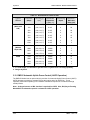
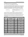
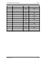
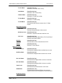
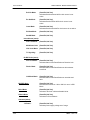
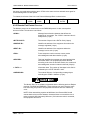
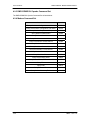
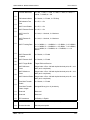
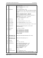
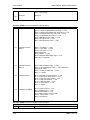
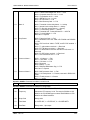
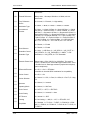
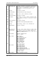
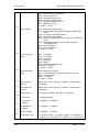
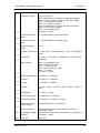
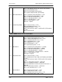
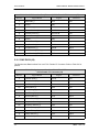
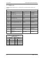
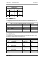
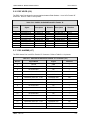
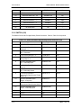
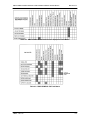
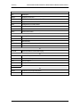
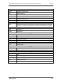
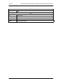
DMD15/DMD15L IBS/IDR Satellite Modem
User Interfaces
Table 5-6. S6 Ground/Deferred – C
Switch Positions
AGC Out
Prompt - C
1
X
1
X
2
X
2
X
3
On
3
Off
4
Off
4
On
5
X
5
X
5.13 TERMINAL (J12)
The Terminal Port is an RS-232 Connection that is used to connect a terminal for operating and
monitoring the system. It is a 9-Pin Female “D” Connector. Refer to Table 5-7 for pinouts.
Table 5-7. Terminal Port (RS-232) 9-Pin Female “D” Connector (J12)
Pin No.
Signal Name
Signal
Direction
3
Transmit Data
TxD
Output
2
Receive Data
RxD
Input
5
Ground
GND
---
7
Request to Send
RTS
Input
8
Clear to Send
CTS
Input
5.14 REMOTE (J13)
The Remote Port is a RS-485 Connection for remote monitor and control of the modem. It is a 9Pin Female “D” Connector. Refer to Table 5-8 for pinouts.
Table 5-8. Remote Port RS-485 9-Pin Female “D” Connector (J13)
Pin No.
Signal Name
Signal
Direction
1
Transmit Data B
RS-485 TxD-B
Output
2
Transmit Clock A
TxC-A
Output
3
Transmit Clock B
TxC-B
Output
4
Receive Clock A
RxC-A
Input
5
Signal Common
Common
---
6
Transmit Data A
RS-485 TxD-A
Output
7
Receive Clock B
RxC-B
Input
8
Receive Data B
RS-485 RxD-B
Input
9
Receive Data A
RS-485 RxD-A
Input
TM051 - Rev. 5.8
5-7