1
Disclaimer
Metapace reserves the right to make changes in specifications and other information contained in this document without prior notice, and the reader should in all
cases consult Metapace to determine whether any such changes have been made.
The information in this publication does not represent a commitment on the part
of Metapace.
Metapace shall not be liable for technical or editorial errors or omissions contained
herein; nor for incidental or consequential damages resulting from the furnishing,
performance, or use of this material.
This document contains proprietary information that is protected by copyright.
All rights are reserved. No part of this document may be photocopied, reproduced,
or translated into another language without the prior written consent of Metapace.
Microsoft® Windows® is a trademark or registered trademark of Microsoft Corporation. Other product names or marks mentioned in this document may be trademarks or registered trademarks of other companies and are the property of their
respective owners.
Table of Contents
Table of Contents
Table of Contents
Chapter 1 - Getting Started
Table of Contents
About
Manual
...................................................... 1-1
Chapter
1 - This
Getting
Started
Wincor
Nixdorf Terminal
Default Settings....................2-8
Unpacking
Your Started
Device............................................... 1-1
Chapter
1
Getting
Wincor Nixdorf Beetle™
Default Settings .....2-8
Terminal Terminal
Default Settings....................2-8
About
This Manual
......................................................
Connecting
the Device
................................................ 1-1
Keyboard
Country
LayoutTerminal
............................................2-9
Wincor
Nixdorf
Beetle™
Default Settings .....2-8
About
This Your
Manual
......................................................
1-1
Unpacking
Device...............................................
Connecting
with
USB ............................................ 1-1
Keyboard Style
..........................................................2-15
Country
Layout ............................................2-9
Unpacking
Your
Device...............................................
1-1
Connecting
the Device
................................................
Connecting
with
Keyboard
Wedge ........................ 1-1
1-2
Keyboard Conversion
................................................2-17
Style ..........................................................2-15
Connecting
USB
............................................ 1-2
1-1
Connecting
the with
Device
................................................
1-1
Reading
Techniques
...................................................
1-3
Control
Character
Output...........................................2-17
Keyboard
Conversion
................................................2-17
Keyboard
Wedge
........................ 1-2
Connecting
USBSettings
............................................
1-1
Menu
Bar Codewith
Security
...............................
1-3
Keyboard
Modifiers....................................................2-18
Control Character
Output...........................................2-17
1-6
Reading
Techniques
...................................................
Connecting
with
Keyboard
Wedge ........................1-3
1-2
Setting
Custom
Defaults
.............................................
1-4
RS232
Baud
Rate......................................................2-20
Keyboard
Modifiers....................................................2-18
1-6
Menu
BarTechniques
Code
Security
Settings
............................... 1-3
Reading
...................................................
1-3
Resetting
the
Custom
Defaults
...................................
1-4
RS232 Word
Data Bits, Stop Bits,
Baud Length:
Rate......................................................2-20
1-7
Setting
Custom
Defaults
.............................................
Resetting
the
Factory
Defaults
....................................
1-5
Menu
Bar
Code
Security
Settings
...............................1-4
1-3
and Parity
RS232
Word................................................................2-21
Length: Data Bits, Stop Bits,
Resetting
the Custom
Defaults
................................... 1-4
1-7
Setting
Custom
Defaults
.............................................
1-4
RS232
Receiver
Time-Out.........................................2-22
and
Parity
................................................................2-21
Chapter
2 - Programming
the Interface
Resetting
the Factory
....................................
1-8
Custom Defaults
Defaults
...................................1-5
1-4
RS232 Handshaking..................................................2-22
Receiver Time-Out.........................................2-22
Resetting
the
Factory
Defaults ....................................
1-5
Timeout
....................................................
2-23
RS232
Handshaking..................................................2-22
Introduction
.................................................................
2-1
Chapter
2RS232
- Programming
the Interface
..........................................................
2-23
RS232 Timeout
....................................................
Programming
the
Interface
Plug and Play ................
2-1
Chapter
2XON/XOFF
- Programming
the-Interface
ACK/NAK
.............................................................
2-23
XON/XOFF
..........................................................
Introduction
.................................................................
2-1
Keyboard
Wedge
........................................................
Scanner
to Bioptic
Communication............................2-24
ACK/NAK
.............................................................
2-23
Programming
the Interface
- Plug and Play ................
2-1
Laptop
Direct
Connect
................................................
Introduction
.................................................................
2-1
Scanner-Bioptic
Packet
Mode
.............................
2-24
Scanner
to
Bioptic
Communication............................2-24
Keyboard
Wedge
USB IBM SurePos.......................................................
2-2
2-4
Programming
the ........................................................
Interface - Plug and Play ................2-1
2-1
Scanner-Bioptic
ACK/NAK
Mode.........................
2-25
Packet
Mode
.............................
2-24
Laptop
Connect
................................................
USB PCDirect
orWedge
Macintosh
Keyboard
................................. 2-1
2-2
2-4
Keyboard
........................................................
2-1
Scanner-Bioptic
ACK/NAK
Timeout.....................
2-25
Mode.........................
USB IBM
SurePos.......................................................
HID......................................................................
2-3
2-5
Laptop
Direct
Connect ................................................2-2
2-1
Scanner-Bioptic
ACK/NAK
Timeout.....................
2-25
USB
PC
or
Macintosh
Keyboard
.................................
2-2
Keyboard
Country
Layout
...........................................
2-4
USB IBM SurePos.......................................................2-9
2-2
Chapter
3 - HID......................................................................
Input/Output
Settings
USB
2-3
Keyboard
Style
..........................................................
2-10
USB PC or Macintosh Keyboard ................................. 2-2
Chapter
3 - Input/Output
Settings
Keyboard
Country
Layout
...........................................2-12
2-4
Conversion................................................
USB
HID......................................................................
2-3
Power
Up Beeper
........................................................3-1
Keyboard
Style
..........................................................
2-10
Control
Character
Output
2-12
Keyboard
Country
Layout..........................................
...........................................
2-4
Beep
on
Character...............................................3-1
Power
UpBEL
Beeper
........................................................3-1
Keyboard Conversion................................................
Modifiers
................................................... 2-12
2-13
Keyboard
Style
..........................................................
2-10
Trigger
Beep
onClick.................................................................3-1
BEL
Character...............................................3-1
Control
Character
Output
..........................................
2-12
Keyboard
Conversion................................................
2-12
Good
Read
and Error Indicators..................................3-2
Trigger
Click.................................................................3-1
Chapter
3
Input/Output
Settings
Keyboard
Modifiers
...................................................
2-13
Control
Character
Output
.......................................... 3-2
2-12
Beeper
–and
Good
Read
.............................................
Good
Read
Error
Indicators..................................3-2
Keyboard
2-13
Volume
–...................................................
Good
Read................................ 3-2
– Good........................................................
Read
.............................................
Power
Up Modifiers
Beeper
3-1
Chapter
3Beeper
- Input/Output
Settings
Beeper
Pitch
–
Good
Read
....................................
3-3
Volume
–
Good
Read................................
3-2
Trigger Click ................................................................ 3-1
Chapter
3Beeper
- Input/Output
Settings
Pitch
Error
..............................................
Good
Read ....................................
Power
Up Beeper
........................................................
3-1
Good
Read
and –
Error
Indicators
.................................3-3
3-2
Beeper
Duration
–
Good
Read
..............................
3-3
Pitch
–
Error
..............................................
Trigger
Click
Beeper
– ................................................................
Good........................................................
Read ............................................ 3-1
3-2
Power
Up
Beeper
3-1
LED
–
Good
Read
.................................................
3-4
Beeper
Duration
–
Good
Read
..............................
3-3
Good
Read
and
Error
Indicators
.................................
3-2
Beeper
Volume
–
Good
Read
...............................
Trigger
Clickof................................................................
3-1
Number
Beeps
–.................................................
Good
Read
............................ 3-4
LED
– Good
Read
Beeper
–
Good
Read
............................................
3-2
Pitch
–
Good
Read
...................................
3-3
Good
Read of
and
Error–Indicators
.................................
3-2
Number
Beeps
Error
.......................................
GoodRead
Read
............................ 3-4
Beeper Volume
– Good
...............................
3-2
Beeper
–ofGood
Read
............................................
3-2
Good
Read
Delay
..................................................
Number
Beeps
–
Error
.......................................
3-4
Beeper
Pitch
– Good
Read
...................................3-5
3-3
Beeper
Volume
– ..................................................
Good
Read
...............................3-5
3-2i
User-Specified
Good
Read
Delay..........................
Good
Read
Delay
Beeper
Pitch
–Good
GoodRead
ReadDelay..........................
...................................3-5
3-3
Manual
Trigger
Mode...................................................3-5
User-Specified
LED
Illumination
- Manual
Trigger............................... 3-6
Manual
Trigger
LED
Illumination
-Mode
Manual
Trigger............................... 3-6 i
In-Stand
SensorMode...................................................3-5
................................................
In-Stand
Sensor
Mode
................................................ 3-6
Presentation
Mode
......................................................
3-7 i
Presentation
Mode
......................................................
LED Illumination
- Presentation
Mode......................... 3-7
ii
LEDPresentation
Illumination -Sensitivity
Presentation
Mode......................... 3-7
.........................................
3-8
ii
Presentation Sensitivity
......................................... 3-8
Centering..........................................
®
Presentation
Centering..........................................3-10
3-8
CodeGate
................................................................
®
CodeGate
................................................................
Mobile Phone
Read Mode......................................... 3-10
3-11
Mobile
Read Mode.........................................
Hands Phone
Free Time-Out
............................................... 3-11
Hands
Time-Out
............................................... 3-11
RereadFree
Delay
............................................................
LED Illumination - Manual Trigger............................... 3-6
In-Stand Sensor Mode ................................................ 3-6
LED
Illumination
- Manual
Trigger............................... 3-6
Presentation
Mode
......................................................
3-7
In-Stand
Sensor
Mode
................................................
3-6
LED Illumination - Presentation Mode......................... 3-7
Presentation
Mode
......................................................
Presentation
Sensitivity
......................................... 3-7
3-8
LEDPresentation
Illumination Centering..........................................
- Presentation Mode......................... 3-7
3-8
®
Presentation
Sensitivity
.........................................
3-8
CodeGate ................................................................ 3-10
Presentation
Centering..........................................
3-8
Mobile
Phone
Read
Mode......................................... 3-11
®
CodeGate
3-10
Hands
Free................................................................
Time-Out ............................................... 3-11
Mobile
Read Mode......................................... 3-11
3-11
RereadPhone
Delay ............................................................
Hands
Free Time-Out
User-Specified
Reread...............................................
Delay.................................... 3-11
3-12
Reread
Delay
............................................................
3-11
Scanner Time-Out ..................................................... 3-12
User-Specified
Reread Delay.................................... 3-13
3-12
Centering...................................................................
Scanner
..................................................... 3-12
No Read Time-Out
....................................................................
3-14
Centering...................................................................
3-13
Video Reverse........................................................... 3-15
No
ReadOrientation
....................................................................
Working
.................................................. 3-14
3-16
Video Reverse........................................................... 3-15
Working
Orientation
Chapter
4 - Data
Editing.................................................. 3-16
Chapter
4 - Data Overview
Editing ................................................. 4-1
Prefix/Suffix
To Add a Prefix or Suffix: ...................................... 4-1
Prefix/Suffix
To Clear Overview
One or All.................................................
Prefixes or Suffixes................ 4-1
4-2
To
Add
a
Prefix
or
Suffix:
......................................
4-1
To Add a Carriage Return Suffix
To Clear
One or All Prefixes
or Suffixes................ 4-3
4-2
to All Symbologies
...........................................
ToSelections
Add a Carriage
Return Suffix
Prefix
.........................................................
4-3
to
All
Symbologies
...........................................
4-3
Suffix Selections.......................................................... 4-4
Prefix
Selections
.........................................................
Function
Code Transmit
.............................................. 4-3
4-4
Suffix
Selections..........................................................
4-4
Intercharacter, Interfunction,
Function
Code Transmit
..............................................
and Intermessage
Delays
......................................... 4-4
4-4
Intercharacter,
Interfunction,
Intercharacter Delay .............................................. 4-5
and
Intermessage
Delays .........................................
User
Specified Intercharacter
Delay...................... 4-4
4-5
Intercharacter
Delay
..............................................
4-5
Interfunction Delay ................................................ 4-6
User
SpecifiedDelay
Intercharacter
Delay...................... 4-6
4-5
Intermessage
..............................................
Interfunction Delay ................................................ 4-6
Delay .............................................. 4-6
Chapter 5Intermessage
- Data Formatting
Chapter
5 -Format
Data Formatting
Data
Editor Introduction .................................. 5-1
Add a Data Format ...................................................... 5-1
Data Format Editor Introduction .................................. 5-1
Other Programming Selections.............................. 5-3
Add a Data Format ...................................................... 5-1
Terminal ID Table ........................................................5-4
Data Format Editor Commands ...................................5-4iii
Move Commands................................................... 5-5
Search Commands ................................................ 5-5iii
Miscellaneous Commands..................................... 5-6
Data Formatter.............................................................5-7
Primary/Alternate Data Formats ..................................5-8
Chapter 6 - Symbologies
All Symbologies ...........................................................6-2
Message Length Description .......................................6-2
OtherID
Programming
Selections.............................. 5-3
Terminal
Table ........................................................5-4
Terminal
ID Table
Data Format
Editor........................................................5-4
Commands ...................................5-4
DataMove
Format
Editor Commands ...................................5-4
Commands...................................................
5-5
Move Commands...................................................
Search
Commands ................................................ 5-5
Search Commands
................................................ 5-5
Miscellaneous
Commands.....................................
5-6
Commands..................................... 5-6
DataMiscellaneous
Formatter.............................................................5-7
Data Formatter.............................................................5-7
Primary/Alternate
Data Formats ..................................5-8
Primary/Alternate Data Formats ..................................5-8
Chapter 6 - Symbologies
Chapter 6 - Symbologies
iv
iv
All Symbologies ...........................................................6-2
All Symbologies
Message
Length...........................................................6-2
Description .......................................6-2
Message.......................................................................6-3
Length Description .......................................6-2
Codabar
Codabar
.......................................................................6-3
Codabar
Concatenation ......................................... 6-4
Codabar
Concatenation ......................................... 6-4
Code
39 .......................................................................6-6
Code
39ASCII...............................................................
.......................................................................6-6
Full
6-8
Full
ASCII...............................................................
Code 39 Code Page .............................................. 6-8
6-9
Code 392Code
Page .............................................. 6-9
Interleaved
of 5 .......................................................6-10
Interleaved
2 of 5 .......................................................6-10
NEC
2 of 5 .................................................................6-11
NEC 293
of.....................................................................6-13
5 .................................................................6-11
Code
Code
93 .....................................................................6-13
Code
93 Code Page ............................................ 6-14
Code293
Code
Page (three-bar
............................................
6-14
Straight
of 5
Industrial
start/stop) ...........6-15
Straight 2 of 5 Industrial
(three-bar
start/stop)
...........6-15
IATA (two-bar
start/stop)
....................6-16
Straight
5 IATA (two-bar start/stop) ....................6-16
Matrix 2 2ofof5 ...............................................................6-17
Matrix128
2 of...................................................................6-18
5 ...............................................................6-17
Code
Code
128128
...................................................................6-18
ISBT
Concatenation...................................... 6-18
ISBT 128
Code
128 Concatenation......................................
Code Page .......................................... 6-18
6-19
Code ....................................................................6-20
128 Code Page .......................................... 6-19
GS1-128
GS1-128
....................................................................6-20
Telepen......................................................................6-21
Telepen......................................................................6-21
UPC-A........................................................................6-22
UPC-A........................................................................6-22
UPC-A/EAN-13
UPC-A/EAN-13
with Extended Coupon Code...................................6-24
with Extended
Coupon
Code...................................6-24
Coupon
GS1 DataBar
Output
....................................6-25
Coupon GS1 DataBar Output ....................................6-25
UPC-E0......................................................................6-25
UPC-E0......................................................................6-25
UPC-E1......................................................................6-28
UPC-E1......................................................................6-28
EAN/JAN-13
..............................................................6-28
EAN/JAN-13
..............................................................6-28
ISBN Translate
.................................................... 6-30
EAN/JAN-8 ................................................................ 6-31
MSI ............................................................................ 6-33
GS1 DataBar Omnidirectional ................................... 6-35
GS1 DataBar Limited ................................................ 6-35
GS1 DataBar Expanded............................................ 6-36
Codablock A .............................................................. 6-37
Codablock F .............................................................. 6-38
PDF417 ..................................................................... 6-39
MacroPDF417 ........................................................... 6-40
MicroPDF417 ............................................................ 6-40
GS1 Composite Codes ............................................. 6-41
UPC/EAN Version ............................................... 6-41
GS1 Emulation .......................................................... 6-42
TCIF Linked Code 39 (TLC39) .................................. 6-43
GS1 DataBar Limited.................................................6-34
GS1 DataBar Expanded ............................................6-35
Codablock A ..............................................................6-36
Codablock F...............................................................6-37
PDF417......................................................................6-38
MacroPDF417............................................................6-39
MicroPDF417.............................................................6-39
GS1 Composite Codes ..............................................6-40
6-41
UPC/EAN Version................................................6-41
6-40
GS1 Emulation...........................................................6-41
6-42
TCIF Linked Code 39 (TLC39) ..................................6-42
6-43
QR Code....................................................................6-43
6-44
QR Code Page ....................................................6-45
6-44
Data Matrix ................................................................6-45
6-46
Data Matrix Code Page .......................................6-47
6-46
Aztec Code ................................................................6-47
6-48
Aztec Code Page .................................................6-49
6-48
Chinese Sensible (Han Xin) Code .............................6-49
6-50
Postal Codes - Linear ................................................6-49
6-50
China Post (Hong Kong 2 of 5) ............................6-50
6-49
Korea Post ...........................................................6-52
6-51
Chapter 7 - Interface Keys
Keyboard Function Relationships ................................7-1
7-1
Supported Interface Keys ............................................7-3
7-3
Chapter 8 - Utilities
iv
To Add a Test Code I.D. Prefix to All
8-1
Symbologies..............................................................8-1
8-1
Show Decoder Revision ..............................................8-1
8-1
Show Scan
Scan Driver
Driver Revision.........................................
Revision......................................... 8-1
Show
8-1
Show Scan
Software
.............................................
8-1
Show
Software
Revision
.............................................8-1
8-1
Driver
Revision.........................................
Show Data
Data Format
Format
......................................................
8-2
Show
......................................................
8-2
Software
Revision
.............................................8-2
8-1
Test Menu
Menu
...................................................................
8-2
Test
Show
Data ...................................................................
Format ......................................................8-2
8-2
Test Menu ................................................................... 8-2
Chapter 99 -- Product
Product Specifications
Chapter
Chapter 9 - Product Specifications
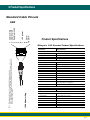
Metapace S-62
S-62 Scanner
Scanner Product
Metapace
Product Specifications
Specifications.........
.........9-1
9-1
Standard Cable
Cable
Pinouts ..............................................
..............................................
Standard
Pinouts
9-2
Metapace
S-62 Scanner
Product Specifications .........9-2
9-1
9-1
Keyboard
Wedge...................................................
9-2
Keyboard
Wedge...................................................
Standard
Cable
Pinouts .............................................. 9-2
9-1
USB
.......................................................................
9-3
USB .......................................................................
Keyboard
Wedge................................................... 9-3
9-2
9-1
..............................................................................
9-4
..............................................................................
9-4
USB
....................................................................... 9-3
.............................................................................. 9-4
Chapter 10
10 -- Maintenance
Maintenance
Chapter
Chapter
10 - Maintenance
Repairs ...................................................................... 10-1
Repairs ...................................................................... 10-1
Maintenance..............................................................
Maintenance..............................................................
10-1
Repairs
......................................................................10-1
Cleaning
the
Device
............................................
10-1
Cleaning the Device ............................................ 10-1
Maintenance..............................................................
Inspecting Cords
Cords and
and Connectors
Inspecting
Connectors.......................
.......................10-1
Cleaning
the
Device
............................................
10-1
Replacing Cables ...................................................... 10-1
Chapter 9 - Product Specifications
Metapace S-62 Scanner Product Specifications ......... 9-1
Standard Cable Pinouts .............................................. 9-2
Keyboard Wedge................................................... 9-2
USB ....................................................................... 9-3
.............................................................................. 9-4
Chapter 10 - Maintenance
Repairs ...................................................................... 10-1
Maintenance.............................................................. 10-1
Cleaning the Device ............................................ 10-1
Inspecting Cords and Connectors ....................... 10-1
Replacing Cables ...................................................... 10-1
Replacing an Interface Cable .............................. 10-2
Troubleshooting a Metapace S-62 Scanner .............. 10-2
Chapter 11 - Customer Support
Technical Assistance ................................................ 11-1
Appendix A - Reference Charts
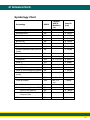
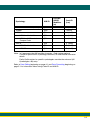
Symbology Chart.........................................................A-1
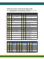
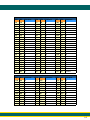
ASCII Conversion Chart (Code Page 1252) ...............A-4
Code Page Mapping of Printed Bar Codes .................A-6
Unicode Key Maps ......................................................A-8
Product Agency Compliance
Europe
The CE marking indicates compliance to 2004/108/EC EMC Directive with Standards EN55022 CLASS B, EN55024, EN61000-3-2,
EN61000-3-3. In addition, complies to 2006/95/EC Low Voltage
v
Directive, when shipped with recommended power supply.
Metapace shall not be liable for use of our product with equipment (i.e., power
supplies, personal computers, etc.) that is not CE marked and does not
comply with the Low Voltage Directive.
Waste Electrical and Electronic Equipment
Information
Metapace complies with Directive 2002/96/EC OF THE EUROPEAN PARLIAMENT AND OF THE COUNCIL of 27 January 2003 on waste electrical and
electronic equipment (WEEE).
This product has required the extraction and use of natural resources for its
production. It may contain hazardous substances that could impact health
and the environment, if not properly disposed.
In order to avoid the dissemination of those substances in our environment
and to diminish the pressure on the natural resources, we encourage you to
use the appropriate take-back systems for product disposal. Those systems will reuse or recycle most of the materials of the product you are disposing in a sound way.
The crossed out wheeled bin symbol informs you that the product
should not be disposed of along with municipal waste and invites you to
use the appropriate separate take-back systems for product disposal.
If you need more information on the collection, reuse, and recycling systems, please contact your local or regional waste administration.
You may also contact your supplier for more information on the environmental performances of this product.
Russia
Gost-R certificate
International
LED Safety Statement
The LED has been tested and classified as “EXEMPT RISK GROUP” to
the standard: IEC 62471:2006.
CB Scheme
Certified to CB Scheme IEC 60950-1, Second Edition.
Solids and Water Protection
The Metapace S-62 has a rating of IP40, immunity of foreign particles and dripping
water.
Required Safety Labels
Warning
!
To reduce the possibility of heat-related injuries, avoid touching sections of the scanner that feel warm.
Compliance Markings
information, Part Number,
and Serial Number
information
1
1 Getting Started
Getting Started
About This Manual
This User’s Guide provides installation and programming instructions for
the Metapace S-62 area-imaging scanner. Product specifications, dimensions,
warranty, and customer support information are also included.
Metapace bar code scanners are factory programmed for the most common terminal and communications settings. If you need to change these settings, programming is accomplished by scanning the bar codes in this guide.
An asterisk (*) next to an option indicates the default setting.
Unpacking Your Device
After you open the shipping carton containing the product, take the following
steps:
• Check for damage during shipment. Report damage immediately to the
carrier who delivered the carton.
• Make sure the items in the carton match your order.
• Save the shipping container for later storage or shipping.
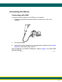
Connecting the Device
Connecting with USB
A scanner can be connected to the USB port of a computer.
1.
Connect the appropriate interface cable to the device first, then to the
computer.
2.
The scanner beeps.
1-1
1-1
Unpacking Your Device
Connecting
the Device
After you open the shipping
carton containing the product, take the following
steps:
• Check
for damage during
Connecting
withshipment.
USB Report damage immediately to the
carrier who delivered the carton.
• Make
sure the
items
the cartonto
match
your order.
A scanner
can
be in
connected
the USB
port of a computer.
• Save
the
shipping
container
for
later
storage
or
shipping.
1. Connect the appropriate interface cable
to the device first, then to the
computer.
Connecting the Device
Connecting with USB
A scanner can be connected to the USB port of a computer.
1.
Connect the appropriate interface cable to the device first, then to the
computer.
2.
The
Thescanner
scannerbeeps.
beeps.
3.
Verify the scanner operation by scanning a bar code from the Sample
Symbols in the back of this manual.
1-1
The unit defaults to a USB PC Keyboard. Refer to page 2-4 for other USB
terminal settings.
For additional USB programming and technical information, refer to “USB
Application Note,” available at www.honeywellaidc.com.
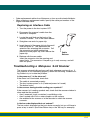
Connecting with Keyboard Wedge
A scanner can be connected between the keyboard and PC as a “keyboard
wedge,” where the scanner provides data output that is similar to keyboard
entries. The following is an example of a keyboard wedge connection:
1.
Turn off power and disconnect the keyboard cable from the back of the
terminal/computer.
1-2
1-2
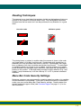
Reading Techniques
The scanner has a view finder that projects a bright red aiming beam that corresponds to the scanner’s horizontal field of view. The aiming beam should be
centered over the bar code, but it can be positioned in any direction for a good
read.
Linear bar code
2D Matrix symbol
The aiming beam or pattern is smaller when the scanner is closer to the code
and larger when it is farther from the code. Symbologies with smaller bars or
elements (mil size) should be read closer to the unit. Symbologies with larger
bars or elements (mil size) should be read farther from the unit. To read single
or multiple symbols (on a page or on an object), hold the scanner at an appropriate distance from the target, press the button, and center the aiming beam or
pattern on the symbol. If the code being scanned is highly reflective (e.g., laminated), it may be necessary to tilt the code up 15° to 18° to prevent unwanted
reflection.
Menu Bar Code Security Settings
Metapace scanners are programmed by scanning menu bar codes or by sending
serial commands to the scanner. If you want to restrict the ability to scan menu
codes, you can use the Menu Bar Code Security settings. Please contact the
nearest technical support office (see Customer Support on page 11-1) for further information.
1-3
1-6
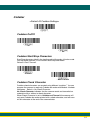
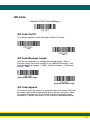
Setting Custom Defaults
You have the ability to create a set of menu commands as your own, custom
defaults. To do so, scan the Set Custom Defaults bar code below before
scannning the menu commands for your custom defaults. If a menu command
requires scanning numeric codes from the back cover, then a Save code, that
entire sequence will be saved to your custom defaults. When you have entered
all the commands you want to save for your custom defaults, scan the Save
Custom Defaults bar code.
Set Custom Defaults
Save Custom Defaults
You may have a series of custom settings and want to correct a single setting.
To do so, just scan the new setting to overwrite the old one. For example, if you
had previously saved the setting for Beeper Volume at Low to your custom
defaults, and decide you want the beeper volume set to High, just scan the Set
Custom Defaults bar code, then scan the Beeper Volume High menu code,
and then Save Custom Defaults. The rest of the custom defaults will remain,
but the beeper volume setting will be updated.
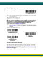
Resetting the Custom Defaults
If you want the custom default settings restored to your scanner, scan the Activate Custom Defaults bar code below. This is the recommended default bar
code for most users. It resets the scanner to the custom default settings. If
there are no custom defaults, it will reset the scanner to the factory default settings. Any settings that have not been specified through the custom defaults
will be defaulted to the factory default settings.
Activate Custom Defaults
1-4
1-7
Resetting the Factory Defaults
!
This selection erases all your settings and resets the scanner to the
original factory defaults. It also disables all plugins.
If you aren’t sure what programming options are in your scanner, or you’ve
changed some options and want to restore the scanner to factory default settings, first scan the Remove Custom Defaults bar code, then scan Activate
Defaults. This resets the scanner to the factory default settings.
Remove Custom Defaults
Activate Defaults
1-5
1-8
22 Programming the Interface
Programming the Interface
Introduction
This chapter describes how to program your system for the desired interface.
Programming the Interface - Plug and Play
Plug and Play bar codes provide instant scanner set up for commonly used
interfaces.
Note: After you scan one of the codes, power cycle the host terminal to have
the interface in effect.
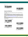
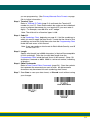
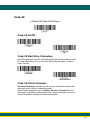
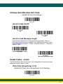
Keyboard Wedge
If you want your system programmed for an IBM PC AT and compatibles keyboard wedge interface with a USA keyboard, scan the bar code below. Keyboard wedge is the default interface.
Note: The following bar code also programs a carriage return (CR) suffix.
IBM PC AT and Compatibles with
CR suffix
Laptop Direct Connect
For most laptops, scanning the Laptop Direct Connect bar code allows operation of the scanner in parallel with the integral keyboard. The following Laptop
Direct Connect bar code also programs a carriage return (CR) suffix and turns
on Emulate External Keyboard (page 2-12).
Laptop Direct Connect
with CR suffix
2-1
2-1
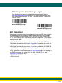
USB IBM SurePos
Scan one of the following “Plug and Play” codes to program the scanner for an
IBM SurePos (USB handheld scanner) or IBM SurePos (USB tabletop scanner)
interface.
Note: After scanning one of these codes, you must power cycle the cash
register.
USB IBM SurePos
(USB Handheld Scanner)
Interface
USB IBM SurePos
(USB Tabletop Scanner)
Interface
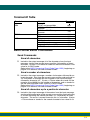
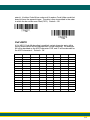
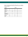
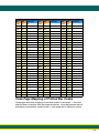
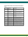
Each bar code above also programs the following suffixes for each symbology:
Symbology
Suffix
Symbology
Suffix
EAN 8
EAN 13
UPC A
UPC E
0C
16
0D
0A
Code 39
Interleaved 2 of 5
Code 128
Code 39
00
00
00
00
0A
0D
18
0A
0B
0B
0B
0B
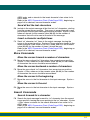
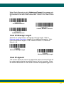
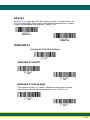
USB PC or Macintosh Keyboard
Scan one of the following codes to program the scanner for USB PC Keyboard
or USB Macintosh Keyboard. Scanning these codes also adds a CR and LF.
USB Keyboard (PC)
USB Keyboard (Mac)
USB Japanese Keyboard (PC)
2-2
2-4
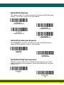
USB HID
Scan the following code to program the scanner for USB HID bar code scanners.
USB HID Bar Code Scanner
2-3
2-5
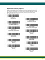
Keyboard Country Layout
Scan the appropriate country code below to program the keyboard layout for
your country or language. As a general rule, the following characters are supported, but need special care for countries other than the United States:
@ | $ # { } [ ] = / ‘ \ < > ~
* United States
United States (Dvorak)
United States (Dvorak left)
United States (Dvorak right)
United States (International)
Albania
Azeri (Cyrillic)
Azeri (Latin)
Belarus
Belgium
Bosnia
Brazil
2-9
2-9
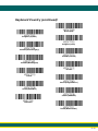
Keyboard Country (continued)
Brazil (MS)
Bulgaria (Cyrillic)
Bulgaria (Latin)
Canada (French legacy)
Canada (French)
Canada (Multilingual)
Croatia
Czech
Czech (Programmers)
Czech (QWERTY)
Czech (QWERTZ)
Denmark
Dutch (Netherlands)
2 - 10
2-10
Keyboard Country (continued)
Estonia
Faeroese
Finland
France
Gaelic
Germany
Greek
Greek (220 Latin)
Greek (220)
Greek (319 Latin)
Greek (319)
Greek (Latin)
Greek (MS)
2 - 11
2-11
Keyboard Country (continued)
Greek (Polytonic)
Hebrew
Hungarian (101 key)
Hungary
Iceland
Irish
Italian (142)
Italy
Japan ASCII
Kazakh
Kyrgyz (Cyrillic)
Latin America
Latvia
2 - 12
2-12
Keyboard Country (continued)
Latvia (QWERTY)
Lithuania
Lithuania (IBM)
Macedonia
Malta
Mongolian (Cyrillic)
Norway
Poland
Polish (214)
Polish (Programmers)
Portugal
Romania
Russia
2 - 13
2-13
Keyboard Country (continued)
Russian (MS)
Russian (Typewriter)
SCS
Serbia (Cyrillic)
Serbia (Latin)
Slovakia
Slovakia (QWERTY)
Slovakia (QWERTZ)
Slovenia
Spain
Spanish variation
Sweden
Switzerland (French)
2 - 14
2-14
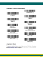
Keyboard Country (continued)
Switzerland (German)
Tatar
Turkey F
Turkey Q
Ukrainian
United Kingdom
United Stated (Dvorak right)
United States (Dvorak left)
United States (Dvorak)
United States (International)
Uzbek (Cyrillic)
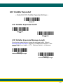
Keyboard Style
This programs keyboard styles, such as Caps Lock and Shift Lock. If you have
used Keyboard Conversion settings, they will override any of the following Keyboard Style settings. Default = Regular.
2 - 15
2-15
Regular is used when you normally have the Caps Lock key off.
* Regular
Caps Lock is used when you normally have the Caps Lock key on.
Caps Lock
Shift Lock is used when you normally have the Shift Lock key on (not common
to U.S. keyboards).
Shift Lock
Automatic Caps Lock is used if you change the Caps Lock key on and off.
The software tracks and reflects if you have Caps Lock on or off . This selection
can only be used with systems that have an LED that notes the Caps Lock status (AT keyboards).
Automatic Caps Lock
Autocaps via NumLock bar code should be scanned in countries (e.g., Germany, France) where the Caps Lock key cannot be used to toggle Caps Lock.
The NumLock option works similarly to the regular Autocaps, but uses the NumLock key to retrieve the current state of the Caps Lock.
Autocaps via NumLock
2 - 16
2-16
Emulate External Keyboard should be scanned if you do not have an external
keyboard (IBM AT or equivalent).
Emulate External Keyboard
Note: After scanning the Emulate External Keyboard bar code, you must power
cycle your computer.
Keyboard Conversion
Alphabetic keyboard characters can be forced to be all upper case or all lowercase. So if you have the following bar code: “abc569GK,” you can make the output “ABC569GK” by scanning Convert All Characters to Upper Case, or to
“abc569gk” by scanning Convert All Characters to Lower Case.
These settings override Keyboard Style selections.
Note: If your interface is a keyboard wedge, first scan the menu code for
Automatic Caps Lock (page 2-16). Otherwise, your output may not be as
expected.
Default = Keyboard Conversion Off.
* Keyboard Conversion Off
Convert All Characters
to Upper Case
Convert All Characters
to Lower Case
Control Character Output
This selection sends a text string instead of a control character. For example,
when the control character for a carriage return is expected, the output would
display [CR] instead of the ASCII code of 0D. Refer to ASCII Conversion Chart
(Code Page 1252) on page A-4. Only codes 00 through 1F are converted (the
first column of the chart).
Note: Control + ASCII Mode overrides this mode.
2 - 17
2-17
Default = Off.
Control Character Output On
* Control Character Output Off
Keyboard Modifiers
This modifies special keyboard features, such as CTRL+ ASCII codes and
Turbo Mode.
Control + ASCII Mode On: The scanner sends key combinations for ASCII
control characters for values 00-1F. Windows is the preferred mode. All keyboard country codes are supported. DOS mode is a legacy mode, and it does
not support all keyboard country codes. New users should use the Windows
mode. Refer to Keyboard Function Relationships, page 7-1 for CTRL+ ASCII
Values.
Windows Mode Prefix/Suffix Off: The scanner sends key combinations for
ASCII control characters for values 00-1F, but it does not transmit any prefix or
suffix information.
Default = Control + ASCII Mode Off.
Windows Mode Control + ASCII
Mode On
* Control + ASCII Mode Off
DOS Mode Control + ASCII Mode
On
Windows Mode Prefix/Suffix Off
2 - 18
2-18
Turbo Mode: The scanner sends characters to a terminal faster. If the terminal
drops characters, do not use Turbo Mode. Default = Off
Turbo Mode On
* Turbo Mode Off
Numeric Keypad Mode: Sends numeric characters as if entered from a
numeric keypad. Default = Off
Numeric Keypad Mode On
* Numeric Keypad Mode Off
Automatic Direct Connect Mode: This selection can be used if you have an
IBM AT style terminal and the system is dropping characters. Default = Off
Automatic Direct Connect Mode
On
* Automatic Direct Connect
Mode Off
2 - 19
2-19
3
3 Input/Output Setting
Input/Output Settings
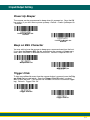
Power Up Beeper
The scanner can be programmed to beep when it’s powered up. Scan the Off
bar code(s) if you don’t want a power up beep. Default = Power Up Beeper On
- Scanner.
Power Up Beeper Off Scanner
* Power Up Beeper On Scanner
Beep on BEL Character
You may wish to force the scanner to beep upon a command sent from the host.
If you scan the Beep on BEL On bar code below, the scanner will beep every
time a BEL character is received from the host. Default = Beep on BEL Off.
*Beep on BEL Off
Beep on BEL On
Trigger Click
To hear an audible click every time the scanner button is pressed, scan the Trigger Click On bar code below. Scan the Trigger Click Off code if you don’t
wish to hear the click. (This feature has no effect on serial or automatic triggering.) Default = Trigger Click Off.
*Trigger Click Off
Trigger Click On
3-1
3-1
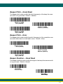
Good Read and Error Indicators
Beeper – Good Read
The beeper may be programmed On or Off in response to a good read.
Turning this option off, only turns off the beeper response to a good read
indication. All error and menu beeps are still audible. Default = Beeper Good Read On.
Beeper - Good Read Off
* Beeper - Good Read On
Beeper Volume – Good Read
The beeper volume codes modify the volume of the beep the scanner
emits on a good read. Default = High.
Low
Medium
* High
Off
3-2
3-2
Beeper Pitch – Good Read
The beeper pitch codes modify the pitch (frequency) of the beep the scanner emits on a good read. Default = Medium.
Low (1600 Hz)
* Medium (2400 Hz)
High (4200 Hz)
Beeper Pitch – Error
The beeper pitch codes modify the pitch (frequency) of the sound the scanner emits when there is a bad read or error. Default = Razz.
* Razz (250 Hz)
Medium (3250 Hz)
High (4200 Hz)
Beeper Duration – Good Read
The beeper duration codes modify the length of the beep the scanner emits
on a good read. Default = Normal.
* Normal Beep
Short Beep
3-3
3-3
LED – Good Read
The LED indicator can be programmed On or Off in response to a good
read. Default = On.
* LED - Good Read On
LED - Good Read Off
Number of Beeps – Good Read
The number of beeps of a good read can be programmed from 1 - 9. The
same number of beeps will be applied to the beeper and LED in response
to a good read. For example, if you program this option to have five beeps,
there will be five beeps and five LED flashes in response to a good read.
The beeps and LED flashes are in sync with one another. To change the
number of beeps, scan the bar code below and then scan a digit (1-9) bar
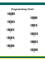
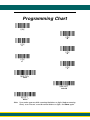
code and the Save bar code on the Programming Chart inside the back
cover of this manual. Default = 1.
Number of Good Read Beeps/LED Flashes
Number of Beeps – Error
The number of beeps and LED flashes emitted by the scanner for a bad
read or error can be programmed from 1 - 9. For example, if you program
this option to have five error beeps, there will be five error beeps and five
LED flashes in response to an error. To change the number of error beeps,
scan the bar code below and then scan a digit (1-9) bar code and the Save
bar code on the Programming Chart inside the back cover of this manual.
Default = 1.
Number of Error Beeps/LED Flashes
3-4
3-4
Good Read Delay
This sets the minimum amount of time before the scanner can read another
bar code. Default = 0 ms (No Delay).
* No Delay
Short Delay (500 ms)
Medium Delay (1,000 ms)
Long Delay (1,500 ms)
User-Specified Good Read Delay
If you want to set your own length for the good read delay, scan the bar
code below, then set the delay (from 0-30,000 milliseconds) by scanning
digits from the inside back cover, then scanning Save.
User-Specified Good Read Delay
Manual Trigger Mode
When in manual trigger mode, the scanner scans until a bar code is read, or
until the button is released. Default = Manual Trigger-Normal.
* Manual Trigger - Normal
3-5
3-5
LED Illumination - Manual Trigger
If you wish to set the illumination LED brightness, scan one of the bar codes
below. This sets the LED illumination for the scanner when the trigger is
pressed. Default = High.
Note: The LEDs are like a flash on a camera. The lower the ambient light in the
room, the brighter the LEDs need to be so the scanner can “see” the bar
codes.
Off
Low
Medium
Medium High
* High
In-Stand Sensor Mode
This feature senses when the scanner is removed from the stand and tells it to
begin manual triggering. When Sensor On is enabled, the scanner defaults to
Presentation Mode when it is in the stand, and to Manual Trigger Mode when it
is removed from the stand. Default = Sensor On.
* Sensor On
Sensor Off
3-6
3-6
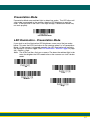
Presentation Mode
Presentation Mode uses ambient light to detect bar codes. The LED dims until
a bar code is presented to the scanner, then the LED brightens to read the
code. If the light level in the room is not high enough, Presentation Mode may
not work properly.
Presentation Mode
LED Illumination - Presentation Mode
If you wish to set the illumination LED brightness, scan one of the bar codes
below. This sets the LED illumination for the scanner when it is in Presentation
Mode. (If the scanner is triggered manually, the LED illumination will switch to
the setting for a manual trigger. See LED Illumination - Manual Trigger on page
3-6.) Default = High.
Note: The LEDs are like a flash on a camera. The lower the ambient light in the
room, the brighter the LEDs need to be so the scanner can “see” the bar
codes.
Off
Low
Medium
* High
3-7
3-7
Presentation Sensitivity
Presentation Sensitivity is a numeric range that increases or decreases the
scanner's reaction time to bar code presentation. To set the sensitivity,
scan the Sensitivity bar code, then scan the degree of sensitivity (from 020) from the inside back cover, and Save. 0 is the most sensitive setting,
and 20 is the least sensitive. Default = 1.
Sensitivity
Presentation Centering
Use Presentation Centering to narrow the scanner’s field of view when it is
in the stand to make sure the scanner reads only those bar codes intended
by the user. For instance, if multiple codes are placed closely together,
Presentation Centering will insure that only the desired codes are read.
Note: To adjust centering when the scanner is hand-held, see
Centering (page 3-13).
If a bar code is not touched by a predefined window, it will not be decoded
or output by the scanner. If Presentation Centering is turned on by scanning Presentation Centering On, the scanner only reads codes that pass
through the centering window you specify using the Top of Presentation
Centering Window, Bottom of Presentation Centering Window, Left,
and Right of Presentation Centering Window bar codes.
3-8
3-8
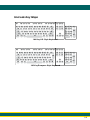
In the example below, the white box is the centering window. The centering
window has been set to 20% left, 30% right, 8% top, and 25% bottom.
Since Bar Code 1 passes through the centering window, it will be read. Bar
Code 2 does not pass through the centering window, so it will not be read.
0%
Bar Code 1
10
Bar Code 2
20
30
40
50
60
70
80
90
100
0
10
20
30
40
50
60
70
80
90
100%
Note: A bar code needs only to be touched by the centering window in
order to be read. It does not need to pass completely through the
centering window.
3-9
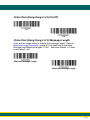
Scan Presentation Centering On, then scan one of the following bar
codes to change the top, bottom, left, or right of the centering window.
Then scan the percent you want to shift the centering window using digits
on the inside back cover of this manual. Scan Save. Default Presentation
Centering = 40% for Top and Left, 60% for Bottom and Right.
Presentation Centering On
* Presentation Centering Off
Top of Presentation Centering
Window
Bottom of Presentation
Centering Window
Left of
Presentation Centering
Window
Right of Presentation Centering
Window
CodeGate®
When CodeGate is On, the button is used to allow decoded data to be transmitted to the host system. The scanner remains on, scanning and decoding bar
codes, but the bar code data is not transmitted until the button is pressed.
When CodeGate is Off, bar code data is transmitted when it is decoded.
Default = CodeGate Off Out-of-Stand.
* CodeGate Off
Out-of-Stand
CodeGate On
Out-of-Stand
3 - 10
3-10
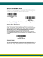
Mobile Phone Read Mode
When this mode is selected, your scanner is optimized to read bar codes from
mobile phone or other LED displays. However, the speed of scanning printed
bar codes may be slightly lower when this mode is enabled.
Hand Held Scanning - Mobile
Phone
Presentation Scanning Mobile Phone
Note: To turn off Mobil Phone Read Mode, scan the Manual Trigger Mode bar
code (see page 3-5).
Hands Free Time-Out
The Scan Stand and Presentation Modes are referred to as “hands free”
modes. If the scanner’s button is pressed when using a hands free mode, the
scanner changes to manual trigger mode. You can set the time the scanner
should remain in manual trigger mode by setting the Hands Free Time-Out.
Once the time-out value is reached, (if there have been no further button
presses) the scanner reverts to the original hands free mode.
Scan the Hands Free Time-Out bar code, then scan the time-out duration
(from 0-300,000 milliseconds) from the inside back cover, and Save. Default =
5,000 ms.
Hands Free Time-Out
Reread Delay
This sets the time period before the scanner can read the same bar code a second time. Setting a reread delay protects against accidental rereads of the
same bar code. Longer delays are effective in minimizing accidental rereads.
3 - 11
3-11
Use shorter delays in applications where repetitive bar code scanning is
required. Reread Delay only works when in Presentation Mode (see page 3-7).
Default = Medium.
Short (500 ms)
* Medium (750 ms)
Long (1000 ms)
Extra Long (2000 ms)
User-Specified Reread Delay
If you want to set your own length for the reread delay, scan the bar code below,
then set the delay (from 0-30,000 milliseconds) by scanning digits from the
inside back cover, then scanning Save.
User-Specified Reread Delay
Scanner Time-Out
Scanner Time-Out powers down the scanner after the unit has been idle for the
specified time. To prevent the scanner from powering down, set this time-out to
0. Scan Scanner Time-Out, then set the time-out by scanning digits (from 0 999,999 ms) from the inside back cover, then scanning Save. Default = 1 ms.
Scanner Time-Out
3 - 12
3-12
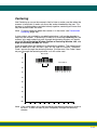
Centering
Use Centering to narrow the scanner’s field of view to make sure that when the
scanner is hand-held, it reads only those bar codes intended by the user. For
instance, if multiple codes are placed closely together, centering will insure that
only the desired codes are read.
Note: To adjust centering when the scanner is in the stand, see Presentation
Centering (page 3-8).
If a bar code is not touched by a predefined window, it will not be decoded or
output by the scanner. If centering is turned on by scanning Centering On, the
scanner only reads codes that pass through the centering window you specify
using the Top of Centering Window, Bottom of Centering Window, Left, and
Right of Centering Window bar codes.
In the example below, the white box is the centering window. The centering window has been set to 20% left, 30% right, 8% top, and 25% bottom. Since Bar
Code 1 passes through the centering window, it will be read. Bar Code 2 does
not pass through the centering window, so it will not be read.
0%
Bar Code 1
10
Bar Code 2
20
30
40
50
60
70
80
90
100
0
10
20
30
40
50
60
70
80
90
100%
Note: A bar code needs only to be touched by the centering window in order to
be read. It does not need to pass completely through the centering
window.
3 - 13
3-13
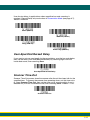
Scan Centering On, then scan one of the following bar codes to change the
top, bottom, left, or right of the centering window. Then scan the percent you
want to shift the centering window using digits on the inside back cover of this
manual. Scan Save. Default Centering = 40% for Top and Left, 60% for Bottom and Right.
Centering On
* Centering Off
Top of Centering Window
Bottom of Centering Window
Left of Centering Window
Right of Centering Window
No Read
With No Read turned On, the scanner notifies you if a code cannot be read.
Default = Off.
On
* Off
If you want a different notation than “NR,” for example, “Error,” or “Bad Code,”
you can edit the output message (see Data Formatting beginning on page 5-1).
The hex code for the No Read symbol is 9C.
3 - 14
3-14
4 Data Editing
Prefix/Suffix Overview
When a bar code is scanned, additional information is sent to the host computer
along with the bar code data. This group of bar code data and additional,
user-defined data is called a “message string.” The selections in this section
are used to build the user-defined data into the message string.
Prefix and Suffix characters are data characters that can be sent before and
after scanned data.Prefix
You can specify
if they
should be sent
Scanned
Data
Suffixwith all symbologies,
or only with specific
symbologies.
1-11
variable length
1-11
alpha numeric &
control characters
alpha numeric &
control characters
Points to Keep In Mind
• It is not necessary to build a message string. The selections in this
chapter are only used if you wish to alter the default settings. Default
prefix = None. Default suffix = None.
• A prefix or suffix may be added or cleared from one symbology or all
Scanned Data
Suffix
symbologies. Prefix
1-11
variable
length
1-11
• You can add any
prefix or suffix from the ASCII Conversion
Chart (Code
alpha numeric &
alpha numeric &
Page 1252), beginning
on page A-4, plus Code I.D.control
and AIM
I.D.
control characters
characters
• You can string together several entries for several symbologies at one
time.
Points to Keep In Mind
• Enter prefixes and suffixes in the order in which you want them to appear
• Itoutput.
is not necessary to build a message string. The selections in this
on the
chapter
arefor
only
used symbologies
if you wish to(as
alter
the default
• When setting up
specific
opposed
to allsettings. Default
prefix
=
None.
Default
suffix
=
None
.
symbologies), the specific symbology ID value counts as an added prefix
• A prefix
or suffix may be added or cleared from one symbology or all
or suffix
character.
symbologies.
• The maximum size of a prefix or suffix configuration is 200 characters,
• You
can add
anyinformation.
prefix or suffix from the ASCII Conversion Chart (Code
which
includes
header
Page 1252), beginning on page A-4, plus Code I.D. and AIM I.D.
• You
can stringor
together
several entries for several symbologies at one
To Add
a Prefix
Suffix:
time.
Step 1.• Scan
Add Prefix
or AddinSuffix
symbol
(page
Enterthe
prefixes
and suffixes
the order
in which
you4-3).
want them to appear
on
the
output.
Step 2. Determine the 2 digit Hex value from the Symbology Chart
• (included
When setting
for specificChart,
symbologies
(ason
opposed
to all
in theup
Symbology
beginning
page A-1)
for the
symbologies), the specific symbology ID value counts as an added prefix
or suffix character.
• The maximum size of a prefix or suffix configuration is 200 characters,
which includes header information.
To Add a Prefix or Suffix:
Step 1. Scan the Add Prefix or Add Suffix symbol (page 4-3).
Step 2. Determine the 2 digit Hex value from the Symbology Chart
(included in the Symbology Chart, beginning on page A-1) for the
4-1
symbology to which you want to apply the prefix or suffix. For
example, for Code 128, Code ID is “j” and Hex ID is “6A”.
Step 3. Scan the 2 hex digits from the Programming Chart inside the back
cover of this manual or scan 9, 9 for all symbologies.
Step 4. Determine the hex value from the ASCII Conversion Chart (Code
Page 1252), beginning on page A-4, for the prefix or suffix you wish
to enter.
Step 5. Scan the 2 digit hex value from the Programming Chart inside the
back cover of this manual.
Step 6. Repeat Steps 4 and 5 for every prefix or suffix character.
Step 7. To add the Code I.D., scan 5, C, 8, 0.
To add AIM I.D., scan 5, C, 8, 1.
To add a backslash (\), scan 5, C, 5, C.
Note: To add a backslash (\) as in Step 7, you must scan 5C twice – once
to create the leading backslash and then to create the backslash
itself.
Step 8. Scan Save to exit and save, or scan Discard to exit without saving.
Repeat Steps 1-6 to add a prefix or suffix for another symbology.
Example: Add a Suffix to a specific symbology
To send a CR (carriage return)Suffix for U.P.C. only:
Step 1. Scan Add Suffix.
Step 2. Determine the 2 digit hex value from the Symbology Chart
(included in the Symbology Chart, beginning on page A-1) for
U.P.C..
Step 3. Scan 6, 3 from the Programming Chart inside the back cover of this
manual.
Step 4. Determine the hex value from the ASCII Conversion Chart (Code
Page 1252), beginning on page A-4, for the CR (carriage return).
Step 5. Scan 0, D from the Programming Chart inside the back cover of this
manual.
Step 6. Scan Save, or scan Discard to exit without saving.
To Clear One or All Prefixes or Suffixes
You can clear a single prefix or suffix, or clear all prefixes/suffixes for a
symbology. If you have been entering prefixes and suffixes for single symbologies, you can use Clear One Prefix (Suffix) to delete a specific character from a symbology. When you Clear All Prefixes (Suffixes), all the
prefixes or suffixes for a symbology are deleted.
4-2
4-2
Step 1. Scan the Clear One Prefix or Clear One Suffix symbol.
Step 2. Determine the 2 digit Hex value from the Symbology Chart
(included in the Symbology Chart, beginning on page A-1) for the
symbology from which you want to clear the prefix or suffix.
Step 3. Scan the 2 digit hex value from the Programming Chart inside the
back cover of this manual or scan 9, 9 for all symbologies.
Your change is automatically saved.
To Add a Carriage Return Suffix to All Symbologies
Scan the following bar code if you wish to add a carriage return suffix to all
symbologies at once. This action first clears all current suffixes, then programs a carriage return suffix for all symbologies.
Add CR Suffix
All Symbologies
Prefix Selections
Add Prefix
Clear One Prefix
Clear All Prefixes
4-3
4-3
Suffix Selections
Add Suffix
Clear One Suffix
Clear All Suffixes
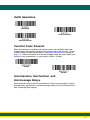
Function Code Transmit
When this selection is enabled and function codes are contained within the
scanned data, the scanner transmits the function code to the terminal. Charts
of these function codes are provided in Supported Interface Keys starting on
page 7-3. When the scanner is in keyboard wedge mode, the scan code is converted to a key code before it is transmitted. Default = Enable.
* Enable
Disable
Intercharacter, Interfunction, and
Intermessage Delays
Some terminals drop information (characters) if data comes through too quickly.
Intercharacter, interfunction, and intermessage delays slow the transmission of
data, increasing data integrity.
4-4
4-4
Intercharacter Delay
An intercharacter delay of up to 5000 milliseconds (in 5ms increments) may
be placed between the transmission of each character of scanned data.
Scan the Intercharacter Delay bar code below, then scan the number of
5ms delays, and the Save bar code using the Programming Chart inside
the back cover of this manual.
Prefix
Scanned Data
1
2
3
4
Suffix
5
Intercharacter Delay
Intercharacter Delay
To remove this delay, scan the Intercharacter Delay bar code, then set the
number of delays to 0. Scan the Save bar code using the Programming
Chart inside the back cover of this manual.
Note: Intercharacter delays are not supported in USB serial emulation.
User Specified Intercharacter Delay
An intercharacter delay of up to 5000 milliseconds (in 5ms increments)
may be placed after the transmission of a particular character of scanned
data. Scan the Delay Length bar code below, then scan the number of
5ms delays, and the Save bar code using the Programming Chart inside
the back cover of this manual.
Next, scan the Character to Trigger Delay bar code, then the 2-digit hex
value for the ASCII character that will trigger the delay ASCII Conversion
Chart (Code Page 1252), beginning on page A-4.
Delay Length
Character to Trigger Delay
To remove this delay, scan the Delay Length bar code, and set the number
of delays to 0. Scan the Save bar code using the Programming Chart
inside the back cover of this manual.
4-5
4-5
Interfunction Delay
An interfunction delay of up to 5000 milliseconds (in 5ms increments) may
be placed between the transmission of each segment of the message
string. Scan the Interfunction Delay bar code below, then scan the number of 5ms delays, and the Save bar code using the Programming Chart
inside the back cover of this manual.
Prefix
STX
1
Scanned Data
HT
2 3 4 5
Suffix
CR
LF
Interfunction Delays
Interfunction Delay
To remove this delay, scan the Interfunction Delay bar code, then set the
number of delays to 0. Scan the Save bar code using the Programming
Chart inside the back cover of this manual.
Intermessage Delay
An intermessage delay of up to 5000 milliseconds (in 5ms increments)
may be placed between each scan transmission. Scan the Intermessage
Delay bar code below, then scan the number of 5ms delays, and the Save
bar code using the Programming Chart inside the back cover of this manual.
1st Scan Transmission
2nd Scan Transmission
Intermessage Delay
Intermessage Delay
To remove this delay, scan the Intermessage Delay bar code, then set the
number of delays to 0. Scan the Save bar code using the Programming
Chart inside the back cover of this manual.
4-6
4-6
5
5 Data Formating
Data Formatting
Data Format Editor Introduction
You may use the Data Format Editor to change the scanner’s output. For example, you can use the Data Format Editor to insert characters at certain points in
bar code data as it is scanned. The selections in the following pages are used
only if you wish to alter the output. Default Data Format setting = None.
Normally, when you scan a bar code, it gets outputted automatically; however
when you create a format, you must use a “send” command (see Send
Commands on page 5-4) within the format program to output data.
Multiple formats may be programmed into the scanner. They are stacked in the
order in which they are entered. However, the following list presents the order
in which formats are applied:
1.
2.
3.
4.
5.
6.
7.
8.
Specific Terminal ID, Actual Code ID, Actual Length
Specific Terminal ID, Actual Code ID, Universal Length
Specific Terminal ID, Universal Code ID, Actual Length
Specific Terminal ID, Universal Code ID, Universal Length
Universal Terminal ID, Actual Code ID, Actual Length
Universal Terminal ID, Actual Code ID, Universal Length
Universal Terminal ID, Universal Code ID, Actual Length
Universal Terminal ID, Universal Code ID, Universal Length
The maximum size of a data format configuration is 2000 bytes, which includes
header information.
If you have changed data format settings, and wish to clear all formats and
return to the factory defaults, scan the Default Data Format code below.
* Default Data Format
Add a Data Format
Step 1. Scan the Enter Data Format symbol (page 5-2).
Step 2. Select Primary/Alternate Format
Determine if this will be your primary data format, or one of 3 alternate
formats. This allows you to save a total of 4 different data formats. To
program your primary format, scan 0 using the Programming Chart
inside the back cover of this manual. If you are programming an
alternate format, scan 1, 2, or 3, depending on which alternate format
5-1
5-1
you are programming. (See Primary/Alternate Data Formats on page
5-8 for further information.)
Step 3. Terminal Type
Refer to Terminal ID Table (page 5-4) and locate the Terminal ID
number for your PC. Scan three numeric bar codes on the inside back
cover to program the scanner for your terminal ID (you must enter 3
digits). For example, scan 0 0 3 for an AT wedge.
Note: The wildcard for all terminal types is 099.
Step 4. Code I.D.
In the Symbology Chart, beginning on page A-1, find the symbology to
which you want to apply the data format. Locate the Hex value for that
symbology and scan the 2 digit hex value from the Programming Chart
inside the back cover of this manual.
Note: If you are creating a data format for Batch Mode Quantity, use 35
for the Code I.D.
Step 5. Length
Specify what length (up to 9999 characters) of data will be acceptable
for this symbology. Scan the four digit data length from the
Programming Chart inside the back cover of this manual. (Note: 50
characters is entered as 0050. 9999 is a universal number, indicating
all lengths.)
Step 6. Editor Commands
Refer to Data Format Editor Commands (page 5-4). Scan the symbols
that represent the command you want to enter. 94 alphanumeric
characters may be entered for each symbology data format.
Step 7. Scan Save to save your data format, or Discard to exit without saving
your changes.
Enter Data Format
Save
Discard
5-2
5-2
Other Programming Selections
Clear One Data Format
This deletes one data format for one symbology. If you are clearing the
primary format, scan 0 from the Programming Chart inside the back
cover of this manual. If you are clearing an alternate format, scan 1, 2,
or 3, depending on the format you are clearing. Scan the Terminal Type
and Code I.D. (see Symbology Chart on page A-1), and the bar code
data length for the specific data format that you want to delete. All other
formats remain unaffected.
Clear all Data Formats
This clears all data formats.
Save to exit and save your data format changes.
Discard to exit without saving any data format changes.
Clear One Data Format
Clear All Data Formats
Save
Discard
5-3
5-3
Terminal ID Table
Terminal
Model(s)
IBM
PC/AT and compatibles
USB SurePOS Handheld
Scanner
USB SurePOS Tabletop
Scanner
True
TTL
Serial
PC Keyboard
Mac Keyboard
Japanese Keyboard (PC)
HID POS
RS232
USB
Terminal
ID
003
128
129
000
000
130
124
125
134
131
Data Format Editor Commands
Send Commands
Send all characters
F1 Include in the output message all of the characters from the input
message, starting from current cursor position, followed by an insert
character. Syntax = F1xx where xx stands for the insert character’s hex
value for its ASCII code.
Refer to the ASCII Conversion Chart (Code Page 1252), beginning on
page A-4 for decimal, hex and character codes.
Send a number of characters
F2 Include in the output message a number of characters followed by an
insert character. Start from the current cursor position and continue for
“nn” characters or through the last character in the input message,
followed by character “xx.” Syntax = F2nnxx where nn stands for the
numeric value (00-99) for the number of characters, and xx stands for
the the insert character’s hex value for its ASCII code.
Refer to the ASCII Conversion Chart (Code Page 1252), beginning on
page A-4 for decimal, hex and character codes.
Send all characters up to a particular character
F3 Include in the output message all characters from the input message,
starting with the character at the current cursor position and continuing
to, but not including, the search character “ss,” followed by an insert
character. The cursor is moved forward to the “ss” character. Syntax
= F3ssxx where ss stands for the search character’s hex value for its
5-4
5-4
ASCII code, and xx stands for the insert character’s hex value for its
ASCII code.
Refer to the ASCII Conversion Chart (Code Page 1252), beginning on
page A-4 for decimal, hex and character codes.
Send all but the last characters
E9 Include in the output message all but the last “nn” characters, starting
from the current cursor position. The cursor is moved forward to one
position past the last input message character included. Syntax = E9nn
where nn stands for the numeric value (00-99) for the number of
characters that will not be sent at the end of the message.
Insert a character multiple times
F4 Send “xx” character “nn” times in the output message, leaving the
cursor in the current position. Syntax = F4xxnn where xx stands for the
insert character’s hex value for its ASCII code, and nn is the numeric
value (00-99) for the number of times it should be sent.
Refer to the ASCII Conversion Chart (Code Page 1252), beginning on
page A-4 for decimal, hex and character codes.
Move Commands
Move the cursor forward a number of characters
F5 Move the cursor ahead “nn” characters from current cursor position.
Syntax = F5nn where nn is the numeric value (00-99) for the number
of characters the cursor should be moved ahead.
Move the cursor backward a number of characters
F6 Move the cursor back “nn” characters from current cursor position.
Syntax = F6nn where nn is the numeric value (00-99) for the number
of characters the cursor should be moved back.
Move the cursor to the beginning
F7 Move the cursor to the first character in the input message. Syntax =
F7.
Move the cursor to the end
EA Move the cursor to the last character in the input message. Syntax =
EA.
Search Commands
Search forward for a character
F8 Search the input message forward for “xx” character from the current
cursor position, leaving the cursor pointing to the “xx” character. Syntax
= F8xx where xx stands for the search character’s hex value for its
ASCII code.
Refer to the ASCII Conversion Chart (Code Page 1252), beginning on
page A-4 for decimal, hex and character codes.
5-5
5-5
Search backward for a character
F9 Search the input message backward for “xx” character from the current
cursor position, leaving the cursor pointing to the “xx” character.
Syntax = F9xx where xx stands for the search character’s hex value for
its ASCII code.
Refer to the ASCII Conversion Chart (Code Page 1252), beginning on
page A-4 for decimal, hex and character codes.
Search forward for a non-matching character
E6 Search the input message forward for the first non-“xx” character from
the current cursor position, leaving the cursor pointing to the non-“xx”
character. Syntax = E6xx where xx stands for the search character’s
hex value for its ASCII code.
Refer to the ASCII Conversion Chart (Code Page 1252), beginning on
page A-4 for decimal, hex and character codes.
Search backward for a non-matching character
E7 Search the input message backward for the first non-“xx” character
from the current cursor position, leaving the cursor pointing to the non“xx” character. Syntax = E7xx where xx stands for the search
character’s hex value for its ASCII code.
Refer to the ASCII Conversion Chart (Code Page 1252), beginning on
page A-4 for decimal, hex and character codes.
Miscellaneous Commands
Suppress characters
FB Suppress all occurrences of up to 15 different characters, starting at the
current cursor position, as the cursor is advanced by other commands.
When the FC command is encountered, the suppress function is
terminated. The cursor is not moved by the FB command.
Syntax = FBnnxxyy . .zz where nn is a count of the number of
suppressed characters in the list, and xxyy .. zz is the list of characters
to be suppressed.
Stop suppressing characters
FC Disables suppress filter and clear all suppressed characters. Syntax =
FC.
Replace characters
E4 Replaces up to 15 characters in the output message, without moving
the cursor. Replacement continues until the E5 command is
encountered. Syntax = E4nnxx1xx2yy1yy2...zz1zz2 where nn is the
total count of of the number of characters in the list (characters to be
replaced plus replacement characters); xx1 defines characters to be
replaced and xx2 defines replacement characters, continuing through
zz1 and zz2.
5-6
5-6
Stop replacing characters
E5 Terminates character replacement. Syntax = E5.
Compare characters
FE Compare the character in the current cursor position to the character
“xx.” If characters are equal, move the cursor forward one position.
Syntax = FExx where xx stands for the comparison character’s hex
value for its ASCII code.
Refer to the ASCII Conversion Chart (Code Page 1252), beginning on
page A-4 for decimal, hex and character codes.
Check for a number
EC Check to make sure there is an ASCII number at the current cursor
position. The format is aborted if the character is not numeric.
Check for non-numeric character
ED Check to make sure there is a non-numeric ASCII character at the
current cursor position. The format is aborted if the character is
numeric.
Insert a delay
EF Inserts a delay of up to 49,995 milliseconds (in multiples of 5), starting
from the current cursor position. Syntax = EFnnnn where nnnn stands
for the delay in 5ms increments, up to 9999. This command can only
be used with keyboard emulation.
Data Formatter
When Data Formatter is turned Off, the bar code data is output to the host as
read, including prefixes and suffixes.
Data Formatter Off
You may wish to require the data to conform to a data format you have created
and saved. The following settings can be applied to your data format:
Data Formatter On, Not Required, Keep Prefix/Suffix
Scanned data is modified according to your data format, and prefixes and
suffixes are transmitted.
Data Format Required, Keep Prefix/Suffix
Scanned data is modified according to your data format, and prefixes and
suffixes are transmitted. Any data that does not match your data format
requirements generates an error tone and the data in that bar code is not
transmitted.
5-7
5-7
Default = Data Formatter On, Not Required, Keep Prefix/Suffix.
* Data Formatter On,
Not Required,
Keep Prefix/Suffix
Data Format Required,
Keep Prefix/Suffix
Primary/Alternate Data Formats
You can save up to four data formats, and switch between these formats. Your
primary data format is saved under 0. Your other three formats are saved under
1, 2, and 3. To set your device to use one of these formats, scan one of the bar
codes below.
Primary Data Format
Data Format 1
Data Format 2
Data Format 3
5-8
5-8
6
6 Symbologies
Symbologies
This programming section contains the following menu selections. Refer to
Chapter 9 for settings and defaults.
• All Symbologies
• Interleaved 2 of 5
• Aztec Code
• Korea Post
• China Post (Hong Kong 2 of 5)
• Matrix 2 of 5
• Chinese Sensible (Han Xin) Code
• MicroPDF417
• Codabar
• MSI
• Codablock A
• NEC 2 of 5
• Codablock F
• Postal Codes - Linear
• Code 128
• PDF417
• Code 39
• GS1 DataBar Omnidirectional
• Code 93
• QR Code
• Data Matrix
• Straight 2 of 5 IATA (two-bar start/
stop)
• EAN/JAN-13
• Straight 2 of 5 Industrial (three-bar
start/stop)
• EAN/JAN-8
• TCIF Linked Code 39 (TLC39)
• GS1 Composite Codes
• Telepen
• GS1 DataBar Expanded
• UPC-A
• GS1 DataBar Limited
• UPC-A/EAN-13 with Extended
Coupon Code
• GS1 DataBar Omnidirectional
• UPC-E0
• GS1 Emulation
• UPC-E1
• GS1-128
6-1
6-1
All Symbologies
If you want to decode all the symbologies allowable for your scanner, scan the
All Symbologies On code. If on the other hand, you want to decode only a
particular symbology, scan All Symbologies Off followed by the On symbol for
that particular symbology.
All Symbologies On
All Symbologies Off
Note: When All Symbologies On is scanned, 2D Postal Codes are not enabled.
2D Postal Codes must be enabled separately.
Message Length Description
You are able to set the valid reading length of some of the bar code symbologies. If the data length of the scanned bar code doesn’t match the valid reading length, the scanner will issue an error tone. You may wish to set the same
value for minimum and maximum length to force the scanner to read fixed
length bar code data. This helps reduce the chances of a misread.
EXAMPLE:
Decode only those bar codes with a count of 9-20 characters.
Min. length = 09Max. length = 20
EXAMPLE:
Decode only those bar codes with a count of 15 characters.
Min. length = 15Max. length = 15
For a value other than the minimum and maximum message length defaults,
scan the bar codes included in the explanation of the symbology, then scan the
digit value of the message length and Save bar codes on the Programming
Chart inside the back cover of this manual. The minimum and maximum
lengths and the defaults are included with the respective symbologies.
6-2
6-2
Codabar
<Default All Codabar Settings>
Codabar On/Off
* On
Off
Codabar Start/Stop Characters
Start/Stop characters identify the leading and trailing ends of the bar code.
You may either transmit, or not transmit Start/Stop characters.
Default = Don’t Transmit.
Transmit
* Don’t Transmit
Codabar Check Character
Codabar check characters are created using different “modulos.” You can
program the scanner to read only Codabar bar codes with Modulo 16 check
characters. Default = No Check Character.
No Check Character indicates that the scanner reads and transmits bar
code data with or without a check character.
When Check Character is set to Validate and Transmit, the scanner will
only read Codabar bar codes printed with a check character, and will transmit this character at the end of the scanned data.
6-3
6-3
When Check Character is set to Validate, but Don’t Transmit, the unit will
only read Codabar bar codes printed with a check character, but will not
transmit the check character with the scanned data.
* No Check Character
Validate Modulo 16, but
Don’t Transmit
Validate Modulo 16
and Transmit
Codabar Concatenation
Codabar supports symbol concatenation. When you enable concatenation, the scanner looks for a Codabar symbol having a “D” start character,
adjacent to a symbol having a “D” stop character. In this case the two messages are concatenated into one with the “D” characters omitted.
A 1 2 3 4 D
D 5 6 7 8 A
Select Require to prevent the scanner from decoding a single “D” Codabar
symbol without its companion. This selection has no effect on Codabar
symbols without Stop/Start D characters.
On
* Off
Require
6-4
6-4
Codabar Message Length
Scan the bar codes below to change the message length. Refer to
Message Length Description (page 6-2) for additional information. Minimum and Maximum lengths = 2-60. Minimum Default = 4, Maximum
Default = 60.
Minimum Message Length
Maximum Message Length
6-5
Code 39
< Default All Code 39 Settings >
Code 39 On/Off
* On
Off
Code 39 Start/Stop Characters
Start/Stop characters identify the leading and trailing ends of the bar code.
You may either transmit, or not transmit Start/Stop characters. Default =
Don’t Transmit.
Transmit
* Don’t Transmit
Code 39 Check Character
No Check Character indicates that the scanner reads and transmits bar
code data with or without a check character.
When Check Character is set to Validate, but Don’t Transmit, the unit
only reads Code 39 bar codes printed with a check character, but will not
transmit the check character with the scanned data.
6-6
6-6
When Check Character is set to Validate and Transmit, the scanner only
reads Code 39 bar codes printed with a check character, and will transmit
this character at the end of the scanned data. Default = No Check Character.
* No Check Character
Validate, but Don’t Transmit
Validate and Transmit
Code 39 Message Length
Scan the bar codes below to change the message length. Refer to
Message Length Description (page 6-2) for additional information. Minimum and Maximum lengths = 0-48. Minimum Default = 0, Maximum
Default = 48.
Minimum Message Length
Maximum Message Length
Code 39 Append
This function allows the scanner to append the data from several Code 39
bar codes together before transmitting them to the host computer. When
the scanner encounters a Code 39 bar code with the append trigger char-
6-7
6-7
acter(s), it buffers Code 39 bar codes until it reads a Code 39 bar code that
does not have the append trigger. The data is then transmitted in the order
in which the bar codes were read (FIFO). Default = Off.
On
* Off
Full ASCII
If Full ASCII Code 39 decoding is enabled, certain character pairs within
the bar code symbol will be interpreted as a single character. For example:
$V will be decoded as the ASCII character SYN, and /C will be decoded as
the ASCII character #. Default = Off.
NUL %U
DLE $P
SP
SPACE 0
0
@
%V
P
P
‘
%W p
+P
SOH $A
DC1 $Q
!
/A
1
1
A
A
Q
Q
a
+A
q
+Q
STX $B
DC2 $R
“
/B
2
2
B
B
R
R
b
+B
r
+R
ETX $C
DC3 $S
#
/C
3
3
C
C
S
S
c
+C
s
+S
EOT $D
DC4 $T
$
/D
4
4
D
D
T
T
d
+D
t
+T
ENQ $E
NAK $U
%
/E
5
5
E
E
U
U
e
+E
u
+U
ACK $F
SYN $V
&
/F
6
6
F
F
V
V
f
+F
v
+V
BEL $G
ETB $W
‘
/G
7
7
G
G
W
W
g
+G
w
+W
BS
$H
CAN $X
(
/H
8
8
H
H
X
X
h
+H
x
+X
HT
$I
EM
$Y
)
/I
9
9
I
I
Y
Y
i
+I
y
+Y
LF
$J
SUB $Z
*
/J
:
/Z
J
J
Z
Z
j
+J
z
+Z
VT
$K
ESC %A
+
/K
;
%F
K
K
[
%K
k
+K
{
%P
FF
$L
FS
%B
,
/L
<
%G L
L
\
%L
l
+L
|
%Q
CR
$M
GS
%C
-
-
=
%H
M
M
]
%M m
+M
}
%R
SO
$N
RS
%D
.
.
>
%I
N
N
^
%N
n
+N
~
%S
SI
$O
US
%E
/
/O
?
%J
O
O
_
%O o
+O
DEL %T
6-8
6-8
Character pairs /M and /N decode as a minus sign and period respectively.
Character pairs /P through /Y decode as 0 through 9.
Full ASCII On
* Full ASCII Off
Code 39 Code Page
Code pages define the mapping of character codes to characters. If the
data received does not display with the proper characters, it may be
because the bar code being scanned was created using a code page that
is different from the one the host program is expecting. If this is the case,
scan the bar code below, select the code page with which the bar codes
were created (see Code Page Mapping of Printed Bar Codes on page A-6),
and scan the value and the Save bar code from the Programming Chart on
the inside the back cover of this manual. The data characters should then
appear properly.
Code 39 Code Page
6-9
6-9
Interleaved 2 of 5
< Default All Interleaved 2 of 5 Settings >
Interleaved 2 of 5 On/Off
* On
Off
Check Digit
No Check Digit indicates that the scanner reads and transmits bar code
data with or without a check digit.
When Check Digit is set to Validate, but Don’t Transmit, the unit only
reads Interleaved 2 of 5 bar codes printed with a check digit, but will not
transmit the check digit with the scanned data.
When Check Digit is set to Validate and Transmit, the scanner only reads
Interleaved 2 of 5 bar codes printed with a check digit, and will transmit this
digit at the end of the scanned data. Default = No Check Digit.
* No Check Digit
Validate, but Don’t Transmit
Validate and Transmit
6 - 10
6-10
Interleaved 2 of 5 Message Length
Scan the bar codes below to change the message length. Refer to
Message Length Description (page 6-2) for additional information. Minimum and Maximum lengths = 2-80. Minimum Default = 4, Maximum
Default = 80.
Minimum Message Length
Maximum Message Length
NEC 2 of 5
< Default All NEC 2 of 5 Settings >
NEC 2 of 5 On/Off
* On
Off
Check Digit
No Check Digit indicates that the scanner reads and transmits bar code
data with or without a check digit.
When Check Digit is set to Validate, but Don’t Transmit, the unit only
reads NEC 2 of 5 bar codes printed with a check digit, but will not transmit
the check digit with the scanned data.
6 - 11
6-11
When Check Digit is set to Validate and Transmit, the scanner only reads
NEC 2 of 5 bar codes printed with a check digit, and will transmit this digit
at the end of the scanned data. Default = No Check Digit.
* No Check Digit
Validate, but Don’t Transmit
Validate and Transmit
NEC 2 of 5 Message Length
Scan the bar codes below to change the message length. Refer to
Message Length Description (page 6-2) for additional information. Minimum and Maximum lengths = 2-80. Minimum Default = 4, Maximum
Default = 80.
Minimum Message Length
Maximum Message Length
6 - 12
6-12
Code 93
< Default All Code 93 Settings >
Code 93 On/Off
* On
Off
Code 93 Message Length
Scan the bar codes below to change the message length. Refer to
Message Length Description (page 6-2) for additional information. Minimum and Maximum lengths = 0-80. Minimum Default = 0, Maximum
Default = 80.
Minimum Message Length
Maximum Message Length
Code 93 Append
This function allows the scanner to append the data from several Code 93
bar codes together before transmitting them to the host computer. When
this function is enabled, the scanner stores those Code 93 bar codes that
start with a space (excluding the start and stop symbols), and does not
immediately transmit the data. The scanner stores the data in the order in
6 - 13
6-13
which the bar codes are read, deleting the first space from each. The
scanner transmits the appended data when it reads a Code 93 bar code
that starts with a character other than a space. Default = Off.
On
* Off
Code 93 Code Page
Code pages define the mapping of character codes to characters. If the
data received does not display with the proper characters, it may be
because the bar code being scanned was created using a code page that
is different from the one the host program is expecting. If this is the case,
scan the bar code below, select the code page with which the bar codes
were created (see Code Page Mapping of Printed Bar Codes on page A-6),
and scan the value and the Save bar code from the Programming Chart on
the inside the back cover of this manual. The data characters should then
appear properly.
Code 93 Code Page
6 - 14
6-14
Straight 2 of 5 Industrial (three-bar start/stop)
<Default All Straight 2 of 5 Industrial Settings>
Straight 2 of 5 Industrial On/Off
On
* Off
Straight 2 of 5 Industrial Message Length
Scan the bar codes below to change the message length. Refer to
Message Length Description (page 6-2) for additional information. Minimum and Maximum lengths = 1-48. Minimum Default = 4, Maximum
Default = 48.
Minimum Message Length
Maximum Message Length
6 - 15
6-15
Straight 2 of 5 IATA (two-bar start/stop)
<Default All Straight 2 of 5 IATA Settings>
Straight 2 of 5 IATA On/Off
On
* Off
Straight 2 of 5 IATA Message Length
Scan the bar codes below to change the message length. Refer to
Message Length Description (page 6-2) for additional information. Minimum and Maximum lengths = 1-48. Minimum Default = 4, Maximum
Default = 48.
Minimum Message Length
Maximum Message Length
6 - 16
6-16
Matrix 2 of 5
<Default All Matrix 2 of 5 Settings>
Matrix 2 of 5 On/Off
On
* Off
Matrix 2 of 5 Message Length
Scan the bar codes below to change the message length. Refer to
Message Length Description (page 6-2) for additional information. Minimum and Maximum lengths = 1-80. Minimum Default = 4, Maximum
Default = 80.
Minimum Message Length
Maximum Message Length
6 - 17
6-17
Code 128
<Default All Code 128 Settings>
Code 128 On/Off
* On
Off
ISBT 128 Concatenation
In 1994 the International Society of Blood Transfusion (ISBT) ratified a
standard for communicating critical blood information in a uniform manner.
The use of ISBT formats requires a paid license. The ISBT 128 Application
Specification describes 1) the critical data elements for labeling blood products, 2) the current recommendation to use Code 128 due to its high
degree of security and its space-efficient design, 3) a variation of Code 128
that supports concatenation of neighboring symbols, and 4) the standard
layout for bar codes on a blood product label. Use the bar codes below to
turn concatenation on or off. Default =Off.
On
* Off
6 - 18
6-18
Code 128 Message Length
Scan the bar codes below to change the message length. Refer to
Message Length Description (page 6-2) for additional information. Minimum and Maximum lengths = 0-80. Minimum Default = 0, Maximum
Default = 80.
Minimum Message Length
Maximum Message Length
Code 128 Append
This function allows the scanner to append the data from several Code 128
bar codes together before transmitting them to the host computer. When
the scanner encounters a Code 128 bar code with the append trigger character(s), it buffers Code 128 bar codes until it reads a Code 128 bar code
that does not have the append trigger. The data is then transmitted in the
order in which the bar codes were read (FIFO). Default = Off.
On
* Off
Code 128 Code Page
Code pages define the mapping of character codes to characters. If the
data received does not display with the proper characters, it may be
because the bar code being scanned was created using a code page that
is different from the one the host program is expecting. If this is the case,
scan the bar code below, select the code page with which the bar codes
were created (see Code Page Mapping of Printed Bar Codes on page A-6),
and scan the value and the Save bar code from the Programming Chart on
the inside the back cover of this manual. The data characters should then
appear properly.
Code 128 Code Page
6 - 19
6-19
GS1-128
<Default All GS1-128 Settings>
GS1-128 On/Off
* On
Off
GS1-128 Message Length
Scan the bar codes below to change the message length. Refer to
Message Length Description (page 6-2) for additional information. Minimum and Maximum lengths = 1-80. Minimum Default = 1, Maximum
Default = 80.
Minimum Message Length
Maximum Message Length
6 - 20
6-20
UPC-A Number System
The numeric system digit of a U.P.C. symbol is normally transmitted at the
beginning of the scanned data, but the unit can be programmed so it will
not transmit it. Default = On.
* On
Off
UPC-A Addenda
This selection adds 2 or 5 digits to the end of all scanned UPC-A data.
Default = Off for both 2 Digit and 5 Digit Addenda.
2 Digit Addenda On
* 2 Digit Addenda Off
5 Digit Addenda On
* 5 Digit Addenda Off
UPC-A Addenda Required
When Required is scanned, the scanner will only read UPC-A bar codes
that have addenda. You must then turn on a 2 or 5 digit addenda listed on
page 6-23. Default = Not Required.
Required
* Not Required
6 - 23
6-23
GS1 Composite Code Message Length
Scan the bar codes below to change the message length. Refer to
Message Length Description (page 6-2) for additional information. Minimum and Maximum lengths = 1-2435. Minimum Default = 1, Maximum
Default = 2435.
Minimum Message Length
Maximum Message Length
GS1 Emulation
The scanner can automatically format the output from any GS1 data carrier to
emulate what would be encoded in an equivalent GS1-128 or GS1 DataBar
symbol. GS1 data carriers include UPC-A and UPC-E, EAN-13 and EAN-8,
ITF-14, GS1-128, and GS1-128 DataBar and GS1 Composites. (Any application that accepts GS1 data can be simplified since it only needs to recognize
one data carrier type.)
If GS1-128 Emulation is scanned, all retail codes (U.P.C., UPC-E, EAN8,
EAN13) are expanded out to 16 digits. If the AIM ID is enabled, the value will
be the GS1-128 AIM ID, ]C1 (see Symbology Chart on page A-1).
If GS1 DataBar Emulation is scanned, all retail codes (U.P.C., UPC-E, EAN8,
EAN13) are expanded out to 16 digits. If the AIM ID is enabled, the value will
be the GS1-DataBar AIM ID, ]em (see Symbology Chart on page A-1).
If GS1 Code Expansion Off is scanned, retail code expansion is disabled, and
UPC-E expansion is controlled by the UPC-E0 Expand (page 6-26) setting. If
the AIM ID is enabled, the value will be the GS1-128 AIM ID, ]C1 (see
Symbology Chart on page A-1).
If EAN8 to EAN13 Conversion is scanned, all EAN8 bar codes are converted
to EAN13 format.
6 - 42
6-24
Coupon GS1 DataBar Output
If you scan coupons that have both UPC and GS1 DataBar codes, you may
wish to scan and output only the data from the GS1 DataBar code. Scan the
GS1 Output On code below to scan and output only the GS1 DataBar code
data. Default = GS1 Output Off.
* GS1 Output Off
GS1 Output On
UPC-E0
<Default All UPC-E Settings>
UPC-E0 On/Off
Most U.P.C. bar codes lead with the 0 number system. To read these
codes, use the UPC-E0 On selection. If you need to read codes that lead
with the 1 number system, use UPC-E1 (page 6-28). Default = On.
* UPC-E0 On
UPC-E0 Off
6 - 25
6-25
UPC-E0 Expand
UPC-E Expand expands the UPC-E code to the 12 digit, UPC-A format.
Default = Off.
On
* Off
UPC-E0 Addenda Required
When Required is scanned, the scanner will only read UPC-E bar codes
that have addenda. Default = Not Required.
Required
* Not Required
UPC-E0 Addenda Separator
When this feature is On, there is a space between the data from the bar
code and the data from the addenda. When turned Off, there is no space.
Default = On.
* On
Off
6 - 26
6-26
UPC-E0 Check Digit
Check Digit specifies whether the check digit should be transmitted at the
end of the scanned data or not. Default = On.
* On
Off
UPC-E0 Number System
The numeric system digit of a U.P.C. symbol is normally transmitted at the
beginning of the scanned data, but the unit can be programmed so it will
not transmit it. To prevent transmission, scan Off. Default = On.
* On
Off
UPC-E0 Addenda
This selection adds 2 or 5 digits to the end of all scanned UPC-E data.
Default = Off for both 2 Digit and 5 Digit Addenda.
2 Digit Addenda On
* 2 Digit Addenda Off
5 Digit Addenda On
* 5 Digit Addenda Off
6 - 27
6-27
UPC-E1
Most U.P.C. bar codes lead with the 0 number system. For these codes, use
UPC-E0 (page 6-25). If you need to read codes that lead with the 1 number
system, use the UPC-E1 On selection. Default = Off.
UPC-E1 On
* UPC-E1 Off
EAN/JAN-13
<Default All EAN/JAN Settings>
EAN/JAN-13 On/Off
* On
Off
EAN/JAN-13 Check Digit
This selection allows you to specify whether the check digit should be
transmitted at the end of the scanned data or not. Default = On.
* On
Off
6 - 28
6-28
EAN/JAN-13 Addenda
This selection adds 2 or 5 digits to the end of all scanned EAN/JAN-13
data. Default = Off for both 2 Digit and 5 Digit Addenda.
2 Digit Addenda On
* 2 Digit Addenda Off
5 Digit Addenda On
* 5 Digit Addenda Off
EAN/JAN-13 Addenda Required
When Required is scanned, the scanner will only read EAN/JAN-13 bar
codes that have addenda. Default = Not Required.
Required
* Not Required
6-29
EAN/JAN-13 Addenda Separator
When this feature is On, there is a space between the data from the bar
code and the data from the addenda. When turned Off, there is no space.
Default = On.
* On
Off
Note: If you want to enable or disable EAN13 with Extended Coupon Code,
refer to UPC-A/EAN-13 with Extended Coupon Code (page 6-24).
ISBN Translate
When On is scanned, EAN-13 Bookland symbols are translated into their
equivalent ISBN number format. Default = Off.
On
* Off
6 - 30
6-30
EAN/JAN-8
<Default All EAN/JAN-8 Settings>
EAN/JAN-8 On/Off
* On
Off
EAN/JAN-8 Check Digit
This selection allows you to specify whether the check digit should be
transmitted at the end of the scanned data or not. Default = On.
* On
Off
6 - 31
6-31
EAN/JAN-8 Addenda
This selection adds 2 or 5 digits to the end of all scanned EAN/JAN-8 data.
Default = Off for both 2 Digit and 5 Digit Addenda.
2 Digit Addenda On
* 2 Digit Addenda Off
5 Digit Addenda On
* 5 Digit Addenda Off
EAN/JAN-8 Addenda Required
When Required is scanned, the scanner will only read EAN/JAN-8 bar
codes that have addenda. Default = Not Required.
Required
* Not Required
EAN/JAN-8 Addenda Separator
When this feature is On, there is a space between the data from the bar
code and the data from the addenda. When turned Off, there is no space.
Default = On.
* On
Off
6 - 32
6-32
MSI
<Default All MSI Settings>
MSI On/Off
On
* Off
MSI Check Character
Different types of check characters are used with MSI bar codes. You can
program the scanner to read MSI bar codes with Type 10 check characters. Default = Validate Type 10, but Don’t Transmit.
When Check Character is set to Validate Type 10/11 and Transmit, the
scanner will only read MSI bar codes printed with the specified type check
character(s), and will transmit the character(s) at the end of the scanned
data.
6 - 33
6-33
When Check Character is set to Validate Type 10/11, but Don’t Transmit,
the unit will only read MSI bar codes printed with the specified type check
character(s), but will not transmit the check character(s) with the scanned
data.
* Validate Type 10, but Don’t
Transmit
Validate Type 10 and Transmit
Validate 2 Type 10 Characters,
but Don’t Transmit
Validate 2 Type 10 Characters
and Transmit
Validate Type 10 then Type 11
Character, but Don’t Transmit
Validate Type 10 then
Type 11 Character and Transmit
Disable MSI Check Characters
MSI Message Length
Scan the bar codes below to change the message length. Refer to
Message Length Description (page 6-2) for additional information. Minimum and Maximum lengths = 4-48. Minimum Default = 4, Maximum
Default = 48.
Minimum Message Length
Maximum Message Length
6 - 34
6-34
GS1 DataBar Omnidirectional
< Default All GS1 DataBar Omnidirectional Settings >
GS1 DataBar Omnidirectional On/Off
* On
Off
GS1 DataBar Limited
< Default All GS1 DataBar Limited Settings >
GS1 DataBar Limited On/Off
* On
Off
6 - 35
6-35
GS1 DataBar Expanded
< Default All GS1 DataBar Expanded Settings >
GS1 DataBar Expanded On/Off
* On
Off
GS1 DataBar Expanded Message Length
Scan the bar codes below to change the message length. Refer to
Message Length Description (page 6-2) for additional information. Minimum and Maximum lengths = 4-74. Minimum Default = 4, Maximum
Default = 74.
Minimum Message Length
Maximum Message Length
6 - 36
6-36
Codablock A
<Default All Codablock A Settings>
Codablock A On/Off
On
* Off
Codablock A Message Length
Scan the bar codes below to change the message length. Refer to
Message Length Description (page 6-2) for additional information. Minimum and Maximum lengths = 1-600. Minimum Default = 1, Maximum
Default = 600.
Minimum Message Length
Maximum Message Length
6 - 37
6-37
Codablock F
<Default All Codablock F Settings>
Codablock F On/Off
On
* Off
Codablock F Message Length
Scan the bar codes below to change the message length. Refer to
Message Length Description (page 6-2) for additional information. Minimum and Maximum lengths = 1-2048. Minimum Default = 1, Maximum
Default = 2048.
Minimum Message Length
Maximum Message Length
6 - 38
6-38
PDF417
< Default All PDF417 Settings >
PDF417 On/Off
* On
Off
PDF417 Message Length
Scan the bar codes below to change the message length. Refer to
Message Length Description (page 6-2) for additional information. Minimum and Maximum lengths = 1-2750. Minimum Default = 1, Maximum
Default = 2750.
Minimum Message Length
Maximum Message Length
6 - 39
6-39
MacroPDF417
MacroPDF417 is an implementation of PDF417 capable of encoding very large
amounts of data into multiple PDF417 bar codes. When this selection is
enabled, these multiple bar codes are assembled into a single data string.
Default = On.
* On
Off
MicroPDF417
< Default All MicroPDF417 Settings >
MicroPDF417 On/Off
On
* Off
6 - 40
6-40
MicroPDF417 Message Length
Scan the bar codes below to change the message length. Refer to
Message Length Description (page 6-2) for additional information. Minimum and Maximum lengths = 1-366. Minimum Default = 1, Maximum
Default = 366.
Minimum Message Length
Maximum Message Length
GS1 Composite Codes
Linear codes are combined with a unique 2D composite component to form a
new class called GS1 Composite symbology. GS1 Composite symbologies
allow for the co-existence of symbologies already in use. Default = Off.
On
* Off
UPC/EAN Version
Scan the UPC/EAN Version On bar code to decode GS1 Composite symbols that have a U.P.C. or an EAN linear component. (This does not affect
GS1 Composite symbols with a GS1-128 or GS1 linear component.)
Default = UPC/EAN Version Off.
UPC/EAN Version On
* UPC/EAN Version Off
Note: If you scan coupons that have both UPC and GS1 DataBar codes, you
may wish to scan and output only the data from the GS1 DataBar code.
See Coupon GS1 DataBar Output (page 6-25) for further information.
6 - 41
6-41
GS1 Composite Code Message Length
Scan the bar codes below to change the message length. Refer to
Message Length Description (page 6-2) for additional information. Minimum and Maximum lengths = 1-2435. Minimum Default = 1, Maximum
Default = 2435.
Minimum Message Length
Maximum Message Length
GS1 Emulation
The scanner can automatically format the output from any GS1 data carrier to
emulate what would be encoded in an equivalent GS1-128 or GS1 DataBar
symbol. GS1 data carriers include UPC-A and UPC-E, EAN-13 and EAN-8,
ITF-14, GS1-128, and GS1-128 DataBar and GS1 Composites. (Any application that accepts GS1 data can be simplified since it only needs to recognize
one data carrier type.)
If GS1-128 Emulation is scanned, all retail codes (U.P.C., UPC-E, EAN8,
EAN13) are expanded out to 16 digits. If the AIM ID is enabled, the value will
be the GS1-128 AIM ID, ]C1 (see Symbology Chart on page A-1).
If GS1 DataBar Emulation is scanned, all retail codes (U.P.C., UPC-E, EAN8,
EAN13) are expanded out to 16 digits. If the AIM ID is enabled, the value will
be the GS1-DataBar AIM ID, ]em (see Symbology Chart on page A-1).
If GS1 Code Expansion Off is scanned, retail code expansion is disabled, and
UPC-E expansion is controlled by the UPC-E0 Expand (page 6-26) setting. If
the AIM ID is enabled, the value will be the GS1-128 AIM ID, ]C1 (see
Symbology Chart on page A-1).
If EAN8 to EAN13 Conversion is scanned, all EAN8 bar codes are converted
to EAN13 format.
6 - 42
6-42
Default = GS1 Emulation Off.
GS1-128 Emulation
GS1 DataBar Emulation
GS1 Code Expansion Off
EAN8 to EAN13 Conversion
* GS1 Emulation Off
TCIF Linked Code 39 (TLC39)
This code is a composite code since it has a Code 39 linear component and a
MicroPDF417 stacked code component. All bar code readers are capable of
reading the Code 39 linear component. The MicroPDF417 component can only
be decoded if TLC39 On is selected. The linear component may be decoded
as Code 39 even if TLC39 is off. Default = Off.
On
* Off
6 - 43
6-43
QR Code
< Default All QR Code Settings >
QR Code On/Off
This selection applies to both QR Code and Micro QR Code.
* On
Off
QR Code Message Length
Scan the bar codes below to change the message length. Refer to
Message Length Description (page 6-2) for additional information. Minimum and Maximum lengths = 1-7089. Minimum Default = 1, Maximum
Default = 7089.
Minimum Message Length
Maximum Message Length
QR Code Append
This function allows the scanner to append the data from several QR Code
bar codes together before transmitting them to the host computer. When
the scanner encounters an QR Code bar code with the append trigger
character(s), it buffers the number of QR Code bar codes determined by
6 - 44
6-44
information encoded in those bar codes. Once the proper number of codes
is reached, the data is output in the order specified in the bar codes.
Default = On.
* On
Off
QR Code Page
QR Code pages define the mapping of character codes to characters. If
the data received does not display with the proper characters, it may be
because the bar code being scanned was created using a code page that
is different from the one the host program is expecting. If this is the case,
scan the bar code below, select the code page with which the bar codes
were created (see Code Page Mapping of Printed Bar Codes on page A-6),
and scan the value and the Save bar code from the Programming Chart on
the inside the back cover of this manual. The data characters should then
appear properly.
QR Code Page
6 - 45
6-45
Data Matrix
< Default All Data Matrix Settings >
Data Matrix On/Off
* On
Off
Data Matrix Message Length
Scan the bar codes below to change the message length. Refer to
Message Length Description (page 6-2) for additional information. Minimum and Maximum lengths = 1-3116. Minimum Default = 1, Maximum
Default = 3116.
Minimum Message Length
Maximum Message Length
Data Matrix Append
This function allows the scanner to append the data from several Data
Matrix bar codes together before transmitting them to the host computer.
When the scanner encounters an Data Matrix bar code with the append
trigger character(s), it buffers the number of Data Matrix bar codes deter-
6 - 46
6-46
mined by information encoded in those bar codes. Once the proper number of codes is reached, the data is output in the order specified in the bar
codes. Default = On.
* On
Off
Data Matrix Code Page
Data Matrix Code pages define the mapping of character codes to characters. If the data received does not display with the proper characters, it may
be because the bar code being scanned was created using a code page
that is different from the one the host program is expecting. If this is the
case, scan the bar code below, select the code page with which the bar
codes were created (see Code Page Mapping of Printed Bar Codes on
page A-6), and scan the value and the Save bar code from the
Programming Chart on the inside the back cover of this manual. The data
characters should then appear properly.
Data Matrix Code Page
6 - 47
6-47
Aztec Code
< Default All Aztec Code Settings >
Aztec Code On/Off
* On
Off
Aztec Code Message Length
Scan the bar codes below to change the message length. Refer to
Message Length Description (page 6-2) for additional information. Minimum and Maximum lengths = 1-3832. Minimum Default = 1, Maximum
Default = 3832.
Minimum Message Length
Maximum Message Length
Aztec Append
This function allows the scanner to append the data from several Aztec bar
codes together before transmitting them to the host computer. When the
scanner encounters an Aztec bar code with the append trigger charac-
6 - 48
6-48
ter(s), it buffers the number of Aztec bar codes determined by information
encoded in those bar codes. Once the proper number of codes is reached,
the data is output in the order specified in the bar codes. Default = Off.
On
* Off
Aztec Code Page
Aztec Code pages define the mapping of character codes to characters. If
the data received does not display with the proper characters, it may be
because the bar code being scanned was created using a code page that
is different from the one the host program is expecting. If this is the case,
scan the bar code below, select the code page with which the bar codes
were created (see Code Page Mapping of Printed Bar Codes on page A-6),
and scan the value and the Save bar code from the Programming Chart on
the inside the back cover of this manual. The data characters should then
appear properly.
Aztec Code Page
6 - 49
6-49
Chinese Sensible (Han Xin) Code
< Default All Han Xin Settings >
Han Xin Code On/Off
On
* Off
Han Xin Code Message Length
Scan the bar codes below to change the message length. Refer to
Message Length Description (page 6-2) for additional information. Minimum and Maximum lengths = 1-7833. Minimum Default = 1, Maximum
Default = 7833.
Minimum Message Length
Maximum Message Length
Postal Codes - Linear
The following lists linear postal codes. Any combination of linear postal code
selections can be active at a time.
China Post (Hong Kong 2 of 5)
<Default All China Post (Hong Kong 2 of 5) Settings>
6 - 50
6-50
China Post (Hong Kong 2 of 5) On/Off
On
* Off
China Post (Hong Kong 2 of 5) Message Length
Scan the bar codes below to change the message length. Refer to
Message Length Description (page 6-2) for additional information.
Minimum and Maximum lengths = 2-80. Minimum Default = 4, Maximum Default = 80.
Minimum Message Length
Maximum Message Length
6-51
Korea Post
<Default All Korea Post Settings>
Korea Post
On
* Off
Korea Post Message Length
Scan the bar codes below to change the message length. Refer to
Message Length Description (page 6-2) for additional information.
Minimum and Maximum lengths = 2-80. Minimum Default = 4, Maximum Default = 48.
Minimum Message Length
Maximum Message Length
Korea Post Check Digit
This selection allows you to specify whether the check digit should be
transmitted at the end of the scanned data. Default = Don’t Transmit.
Transmit Check Digit
* Don’t Transmit Check Digit
6-52
7
7 Interface Keys
Interface Keys
Keyboard Function Relationships
The following Keyboard Function Code, Hex/ASCII Value, and Full ASCII
“CTRL”+ relationships apply to all terminals that can be used with the scanner.
Refer to page 2-18 enable Control + ASCII mode.
Function Code
NUL
SOH
STX
ETX
EOT
ENQ
ACK
BEL
BS
HT
LF
VT
FF
CR
SO
SI
DLE
DC1
DC2
DC3
DC4
NAK
SYN
ETB
CAN
EM
SUB
ESC
FS
GS
RS
US
HEX/ASCII Value
00
01
02
03
04
05
06
07
08
09
0A
0B
0C
0D
0E
0F
10
11
12
13
14
15
16
17
18
19
1A
1B
1C
1D
1E
1F
Full ASCII “CTRL” +
@
A
B
C
D
E
F
G
H
I
J
K
L
M
N
O
P
Q
R
S
T
U
V
W
X
Y
Z
[
\
]
^
_
7-1
7-1
The last five characters in the Full ASCII “CTRL”+ column ( [ \ ] 6 - ), apply to
US only. The following chart indicates the equivalents of these five characters
for different countries.
Country
Codes
United States
[
\
]
6
-
Belgium
[
<
]
6
-
Scandinavia
8
<
9
6
-
France
^
8
$
6
=
Germany
Ã
+
6
-
Italy
\
+
6
-
Switzerland
<
..
6
-
United Kingdom
[
¢
]
6
-
Denmark
8
\
9
6
-
Norway
8
\
9
6
-
Spain
[
\
]
6
-
7-2
7-2
Supported Interface Keys
ASCII
HEX
NUL
SOH
STX
ETX
EOT
ENQ
ACK
BEL
BS
HT
LF
VT
FF
CR
SO
SI
DLE
DC1
DC2
DC3
DC4
NAK
SYN
ETB
CAN
EM
SUB
ESC
FS
GS
RS
US
DEL
00
01
02
03
04
05
06
07
08
09
0A
0B
0C
0D
0E
0F
10
11
12
13
14
15
16
17
18
19
1A
1B
1C
1D
1E
1F
7F
IBM PC/AT and
Compatibles,
USB PC
Keyboard
Reserved
Enter (KP)
Cap Lock
ALT make
ALT break
CTRL make
CTRL break
CR/Enter
Reserved
Tab
Reserved
Tab
Delete
CR/Enter
Insert
Escape
F11
Home
Print
Back Space
Back Tab
F12
F1
F2
F3
F4
F5
F6
F7
F8
F9
F10
Apple Mac/iMac
Supported Keys
Reserved
Enter/Numpad Enter
CAPS
ALT make
ALT break
CNTRL make
CNTRL break
RETURN
APPLE make
TAB
APPLE break
TAB
Del
RETURN
Ins Help
ESC
F11
Home
Prnt Scrn
BACKSPACE
LSHIFT TAB
F12
F1
F2
F3
F4
F5
F6
F7
F8
F9
F10
BACKSPACE
7-3
7-3
8
8 Utilities
Utilities
To Add a Test Code I.D. Prefix to All Symbologies
This selection allows you to turn on transmission of a Code I.D. before the
decoded symbology. (See the Symbology Chart, beginning on page A-1) for
the single character code that identifies each symbology.) This action first
clears all current prefixes, then programs a Code I.D. prefix for all symbologies.
This is a temporary setting that will be removed when the unit is power cycled.
Add Code I.D. Prefix to
All Symbologies (Temporary)
Show Decoder Revision
Scan the bar code below to output the decoder revision.
Show Decoder Revision
Show Scan Driver Revision
Scan the bar code below to output the scan driver revision. The scan driver
controls image capture.
Show Scan Driver Revision
Show Software Revision
Scan the bar code below to output the current software revision, unit serial number, and other product information.
Show Revision
8-1
8-1
Show Data Format
Scan the bar code below to show current data format settings.
DFMBK3?.
Data Format Settings
Test Menu
When you scan the Test Menu On code, then scan a programming code in this
manual, the scanner displays the content of a programming code. The programming function will still occur, but in addition, the content of that programming code is output to the terminal.
Note: This feature should not be used during normal scanner operation.
On
* Off
8-2
8-2
9 Product Specifications
Standard Cable Pinouts
Data +
Data -
+5V power
9
Product Specifications
1
2
3
4
5
6
7
8
9
10
Cable shield
Cable select
Supply ground
USB
0HWDSDFH6 Scanner Product Specifications
Parameter
Specification
Height
2.9 inches (75mm)
Length
6.7 inches (170mm)
Width
2.6 inches (66mm)
Weight
4.2 ounces (119g)
Electrical
Input Voltage
4 to 5.5VDC
Operating Power
2W; 400 mA (typical) @ 5V
Standby Power
.45W; 90 mA (typical) @ 5V
Environmental
Operating Temperature
32°F to 104°F (0°C to 40°C)
Storage Temperature
-40°F to 140°F (-40°C to 60°C)
Humidity
0 to 95% non-condensing
Drop
Operational after 12 drops to concrete from 2 ft. (1m)
Environmental Sealing
IP40
Light Levels
0 - 100,000 lux (direct sunlight)
ESD
Up to 10kv direct air
Up to 4kv indirect coupling plane
Motion Tolerance
100mm per second for 13 mil UPC
Scan Performance
Pitch, Skew
60°, 70°
Symbol Contrast
35%
DOF with 5 mil, 1D bar code
10 Pin Modular Plug
Note: Pin assignments are not compatible with legacy products.
Use of a cable with improper pin assignments may lead to damage to the unit.
Use of any cables not provided by the manufacturer may result in damage not
covered by your warranty.
Mechanical
Typical Performance
5 mil Code 39
33 - 95mm (1.3 - 3.7 in.)
13 mil UPC-A
32 - 255mm (1.3 - 10 in.)
20 mil Code 39
35 - 355mm (1.4 - 14 in.)
6.7 mil PDF417
30 - 95mm (1.2 - 3.7 in.)
10mil Data Matrix
30 - 100mm (1.2 - 3.9 in.)
15mil Data Matrix
21 - 162mm (0.8 - 6.4 in.)
20mil QR Code
23 - 200mm (0.9 - 7.9 in.)
9-1
11
10 Maintenance
Maintenance
Repairs
Repairs and/or upgrades are not to be performed on this product. These services are to be performed only by an authorized service center (see Customer
Support on page 12-1).
Maintenance
Your device provides reliable and efficient operation with a minimum of care.
Although specific maintenance is not required, the following periodic checks
ensure dependable operation:
Cleaning the Device
Reading performance may degrade if the scanner’s window is not clean. If
the window is visibly dirty, or if the scanner isn’t operating well, clean the
window with a soft cloth or lens tissue dampened with water (or a mild
detergent- water solution). If a detergent solution is used, rinse with a
clean lens tissue dampened with water only.
The scanner and base’s housing may also be cleaned the same way.
!
Caution:
Do not submerge the scanner in water. The scanner’s
housing is not watertight.
Do not use abrasive wipes or tissues on the scanner’s
window – abrasive wipes may scratch the window. Never
use solvents (e.g., alcohol or acetone) on the housing or
window – solvents may damage the finish or the window.
Inspecting Cords and Connectors
Inspect the interface cable and connector for wear or other signs of damage. A badly worn cable or damaged connector may interfere with scanner
operation. Contact your distributor for information about cable replacement. Cable replacement instructions are on page 11-1.
Replacing Cables
The standard interface cable is attached to the scanner with an 10-pin modular
connector. When properly seated, the connector is held in the scanner’s handle
by a flexible retention tab. The interface cable is designed to be field replaceable.
11 - 1
10-1
• Order replacement cables from Metapace or from an authorized distributor.
• When ordering a replacement cable, specify the cable part number of the
original interface cable.
Replacing an Interface Cable
1. Turn the power to the host system OFF.
2. Disconnect the scanner’s cable from the
terminal or computer.
3. Locate the small hole on the back of the
scanner’s handle. This is the cable release.
4. Straighten one end of a paper clip.
5. Insert the end of the paper clip into the small
hole and press in. This depresses the
retention tab, releasing the connector. Pull
the connector out while maintaining
pressure on the paper clip, then remove the
paper clip.
Cable
Release
6. Replace with the new cable.
Insert the connector into the opening and
press firmly. The connector is keyed to go in only one way, and will
click into place.
Troubleshooting a Metapace S-62 Scanner
The scanner automatically performs self-tests whenever you turn it on. If
your scanner is not functioning properly, review the following Troubleshooting Guide to try to isolate the problem.
Is the power on? Is the aimer on?
If the aimer isn’t illuminated, check that:
• The cable is connected properly.
• The host system power is on (if external power isn’t used).
• The button works.
Is the scanner having trouble reading your symbols?
If the scanner isn’t reading symbols well, check that the scanner window is
clean and that the symbols:
• Aren’t smeared, rough, scratched, or exhibiting voids.
• Aren’t coated with frost or water droplets on the surface.
• Are enabled in the scanner or in the decoder to which the scanner
connects.
Is the bar code displayed but not entered?
The bar code is displayed on the host device correctly, but you still have to
press a key to enter it (the Enter/Return key or the Tab key, for example).
10 - 2
10-2
• You need to program a suffix. Programming a suffix enables the scanner
to output the bar code data plus the key you need (such as “CR”) to enter
the data into your application. Refer to Prefix/Suffix Overview beginning
on page 4-1 for further information.
Does the scanner read the bar code incorrectly?
If the scanner reads a bar code, but the data is not displayed correctly on
the host screen:
• The scanner may not be programmed for the appropriate terminal
interface.
For example, you scan “12345” and the host displays “@es%.”
Reprogram the scanner with the correct Plug and Play bar code. See
Programming the Interface beginning on page 2-1.
• The scanner may not be programmed to output your bar code data
properly.
For example, you scan “12345” and the host displays “A12345B.”
Reprogram the scanner with the proper symbology selections. See
Chapter 6.
The scanner won’t read your bar code at all.
1. Scan the sample bar codes in the back of this manual. If the scanner
reads the sample bar codes, check that your bar code is readable.
Verify that your bar code symbology is enabled (see Chapter 6).
If the scanner still can’t read the sample bar codes, scan All Symbologies
(page 6-2).
If you aren’t sure what programming options have been set in the scanner,
or if you want the factory default settings restored, refer to Resetting the
Factory Defaults on page 1-8.
11 - 3
10-3
11 Customer Support
Technical Assistance
Contact information for technical support, product service, and repair can be
found at www.metapace.com.
Limited Warranty
Metapace warrants its products to be free from defects in materials and workmanship and to conform to Metapace published specifications applicable to the products purchased at the time of shipment. This warranty does not cover any
Metapace product which is (i) improperly installed or used; (ii) damaged by accident
or negligence, including failure to follow the proper maintenance, service, and
cleaning schedule; or (iii) damaged as a result of (A) modification or alteration
by the purchaser or other party, (B) excessive voltage or current supplied to or
drawn from the interface connections, (C) static electricity or electro-static discharge, (D) operation under conditions beyond the specified operating parameters, or (E) repair or service of the product by anyone other than Metapace or its
authorized representatives.
This warranty shall extend from the time of shipment for the duration published
by Metapace for the product at the time of purchase ("Warranty Period"). Any
defective product must be returned (at purchaser’s expense) during the Warranty Period to Metapace factory or authorized service center for inspection. No
product will be accepted by Metapace without a Return Materials Authorization,
which may be obtained by contacting Metapace. In the event that the product is
returned to Metapace or its authorized service center within the Warranty Period
and Metapace determines to its satisfaction that the product is defective due to
defects in materials or workmanship,Metapace, at its sole option, will either repair or
replace the product without charge, except for return shipping to Metapace.
EXCEPT AS MAY BE OTHERWISE PROVIDED BY APPLICABLE LAW, THE
FOREGOING WARRANTY IS IN LIEU OF ALL OTHER COVENANTS OR
WARRANTIES, EITHER EXPRESSED OR IMPLIED, ORAL OR WRITTEN,
INCLUDING, WITHOUT LIMITATION, ANY IMPLIED WARRANTIES OF MERCHANTABILITY OR FITNESS FOR A PARTICULAR PURPOSE, OR NONINFRINGEMENT.
METAPACE’S RESPONSIBILITY AND PURCHASER’S EXCLUSIVE REMEDY
UNDER THIS WARRANTY IS LIMITED TO THE REPAIR OR REPLACEMENT
OF THE DEFECTIVE PRODUCT WITH NEW OR REFURBISHED PARTS. IN
NO EVENT SHALL Metapace BE LIABLE FOR INDIRECT, INCIDENTAL, OR CONSEQUENTIAL DAMAGES, AND, IN NO EVENT, SHALL ANY LIABILITY OF
Metapace ARISING IN CONNECTION WITH ANY PRODUCT SOLD HEREUNDER (WHETHER SUCH LIABILITY ARISES FROM A CLAIM BASED ON
CONTRACT, WARRANTY, TORT, OR OTHERWISE) EXCEED THE ACTUAL
AMOUNT PAID TO Metapace FOR THE PRODUCT. THESE LIMITATIONS ON
LIABILITY SHALL REMAIN IN FULL FORCE AND EFFECT EVEN WHEN Metapace MAY HAVE BEEN ADVISED OF THE POSSIBILITY OF SUCH INJURIES,
LOSSES, OR DAMAGES. SOME STATES, PROVINCES, OR COUNTRIES DO
NOT ALLOW THE EXCLUSION OR LIMITATIONS OF INCIDENTAL OR CONSEQUENTIAL DAMAGES, SO THE ABOVE LIMITATION OR EXCLUSION
MAY NOT APPLY TO YOU.
11-1
All provisions of this Limited Warranty are separate and severable, which
means that if any provision is held invalid and unenforceable, such determinationshall not affect the validity of enforceability of the other provisions
hereof. Use of any peripherals not provided by the manufacturer may result
in damage not covered by this warranty. This includes but is not limited to:
cables, power supplies, cradles, and docking stations. Metapace extends
these warranties only to the first end-users of the products. These warranties are non-transferable. The duration of the limited warranty for the Metapace S-62 scanner is one (1) year.
11-2
A
A1 Reference Charts
Reference Charts
Symbology Chart
Symbology
AIM ID
Possible
AIM ID
Modifiers
( m)
All Symbologies
Code ID
(hex)
(0x99)
Australian Post
]X0
Aztec Code
]zm
A (0x41)
0-9, A-C
Batch Mode Quantity
z (0x7A)
5 (0x35)
British Post
]X0
B (0x42)
Canadian Post
]X0
C (0x43)
China Post
]X0
Q (0x51)
Chinese Sensible Code (Han Xin
Code)
]X0
H (0x48)
Codabar
]Fm
0-1
a (0x61)
Codablock A
]O6
0, 1, 4, 5, 6
V (0x56)
Codablock F
]Om
0, 1, 4, 5, 6
q (0x71)
Code 11
]H3
Code 128
]Cm
GS1-128
h (0x68)
0, 1, 2, 4
j (0x6A)
]C1
I (0x49)
Code 32 Pharmaceutical (PARAF)
]X0
< (0x3C)
Code 39 (supports Full ASCII
mode)
]Am
0, 1, 3, 4, 5, 7
b (0x62)
Code 49
]Tm
0, 1, 2, 4
l (0x6C)
Code 93 and 93i
]Gm
0-9, A-Z,
a-m
i (0x69)
Data Matrix
]dm
0-6
w (0x77)
EAN-13 (including Bookland EAN)
]E0
d (0x64)
EAN-13 with Add-On
]E3
d (0x64)
EAN-13 with Extended
Coupon Code
]E3
d (0x64)
]E4
D (0x44)
EAN-8
A-1
A-1
Symbology
EAN-8 with Add-On
AIM ID
Possible
AIM ID
Modifiers
( m)
]E3
Code ID
(hex)
D (0x44)
GS1 Composite
]em
0-3
y (0x79)
GS1 DataBar
]em
0
y (0x79)
GS1 DataBar Limited
]em
{ (0x7B)
GS1 DataBar Omnidirectional
]em
y (0x79)
GS1 DataBar Expanded
]em
} (0x7D)
InfoMail
]X0
, (0x2c)
Intelligent Mail Bar Code
]X0
M (0x4D)
Interleaved 2 of 5
]Im
Japanese Post
]X0
J (0x4A)
KIX (Netherlands) Post
]X0
K (0x4B)
Korea Post
]X0
? (0x3F)
Matrix 2 of 5
]X0
m (0x6D)
MaxiCode
]Um
0-3
x (0x7 8)
MicroPDF417
]Lm
3-5
R (0x52)
MSI
]Mm
0
g (0x67)
NEC 2 of 5
]X0
Y (0x59)
OCR MICR (E 13 B)
]o3
O (0x4F)
OCR SEMI Font
]o3
O (0x4F)
OCR-A
]o1
O (0x4F)
OCR-B
]o2
O (0x4F)
PDF417
]Lm
Planet Code
]X0
L (0x4C)
Postal-4i
]X0
N (0x4E)
Postnet
]X0
P (0x50)
QR Code and Micro QR Code
]Qm
0-6
s (0x73)
Straight 2 of 5 IATA
]Rm
0, 1, 3
f (0x66)
Straight 2 of 5 Industrial
]S0
0, 1, 3
0-2
e (0x65)
r
(0x72)
f (0x66)
A-2
A-2
Possible
AIM ID
Modifiers
(m)
Code ID
(hex)
Symbology
AIM ID
TCIF Linked Code 39 (TLC39)
]L2
T (0x54)
Telepen
]Bm
t (0x54)
UPC-A
]E0
c (0x63)
UPC-A with Add-On
]E3
c (0x63)
UPC-A with Extended
Coupon Code
]E3
c (0x63)
]E0
E (0x45)
UPC-E with Add-On
]E3
E (0x45)
UPC-E1
]X0
E (0x45)
UPC-E
Note: “m” represents the AIM modifier character. Refer to International
Technical Specification, Symbology Identifiers, for AIM modifier character
details.
Prefix/Suffix entries for specific symbologies override the universal (All
Symbologies, 99) entry.
Refer to Data Editing beginning on page 4-1 and Data Formatting beginning on
page 5-1 for information about using Code ID and AIM ID.
A-3
A-3
ASCII Conversion Chart (Code Page 1252)
Note: This table applies to U.S. style keyboards. Certain characters may differ
depending on your Country Code/PC regional settings.
Non-Printable Characters
DEC HEX Character (Code)
0
1
0
1
2
3
4
2
3
4
5
DEC HEX Character (Code)
16
17
10
11
DATA LINK ESCAPE (DLE)
DEVICE CONTROL 1 (DC1)
18
19
20
12
13
14
DEVICE CONTROL 2 (DC2)
DEVICE CONTROL 3 (DC3)
DEVICE CONTROL 4 (DC4)
5
NULL
START OF HEADING
(SOH)
START OF TEXT (STX)
END OF TEXT (ETX)
END OF TRANSMISSION
(EOT)
END OF QUERY (ENQ)
21
15
6
7
6
7
ACKNOWLEDGE (ACK)
BEEP (BEL)
22
23
16
17
8
9
10
11
12
8
9
A
B
C
BACKSPACE (BS)
HORIZONTAL TAB (HT)
LINE FEED (LF)
VERTICAL TAB (VT)
FF (FORM FEED)
24
25
26
27
28
18
19
1A
1B
1C
13
D
CR (CARRIAGE RETURN) 29
1D
14
E
SO (SHIFT OUT)
30
1E
15
F
SI (SHIFT IN)
31
1F
NEGATIVE ACKNOWLEDGEMENT (NAK)
SYNCHRONIZE (SYN)
END OF TRANSMISSION
BLOCK (ETB)
CANCEL (CAN)
END OF MEDIUM (EM)
SUBSTITUTE (SUB)
ESCAPE (ESC)
FILE SEPARATOR (FS)
RIGHT ARROW
GROUP SEPARATOR (GS)
LEFT ARROW
RECORD SEPARATOR (RS)
UP ARROW
UNIT SEPARATOR (US)
DOWN ARROW
Printable Characters
DEC
HEX
32
33
34
35
36
37
38
39
20
21
22
23
24
25
26
27
Character
<SPACE>
!
"
#
$
%
&
'
DEC
HEX
64
65
66
67
68
69
70
71
40
41
42
43
44
45
46
47
Character
@
A
B
C
D
E
F
G
DEC
96
97
98
99
100
101
102
103
HEX
60
61
62
63
64
65
66
67
Character
`
a
b
c
d
e
f
g
A-4
A-4
Printable Characters (Continued)
DEC
HEX
40
41
42
43
44
45
46
47
48
49
50
51
52
53
54
55
56
57
58
59
60
61
62
63
28
29
2A
2B
2C
2D
2E
2F
30
31
32
33
34
35
36
37
38
39
3A
3B
3C
3D
3E
3F
Character
(
)
*
+
,
.
/
0
1
2
3
4
5
6
7
8
9
:
;
<
=
>
?
DEC
HEX
72
73
74
75
76
77
78
79
80
81
82
83
84
85
86
87
88
89
90
91
92
93
94
95
48
49
4A
4B
4C
4D
4E
4F
50
51
52
53
54
55
56
57
58
59
5A
5B
5C
5D
5E
5F
Character
H
I
J
K
L
M
N
O
P
Q
R
S
T
U
V
W
X
Y
Z
[
\
]
^
_
DEC
HEX
Character
104
105
106
107
108
109
110
111
112
113
114
115
116
117
118
119
120
121
122
123
124
125
126
127
68
69
6A
6B
6C
6D
6E
6F
70
71
72
73
74
75
76
77
78
79
7A
7B
7C
7D
7E
7F
h
i
j
k
l
m
n
o
p
q
r
s
t
u
v
w
x
y
z
{
|
}
~
<DEL>
Extended ASCII Characters
DEC HEX
128
129
130
131
132
133
134
135
136
137
138
139
80
81
82
83
84
85
86
87
88
89
8A
8B
Character
€
‚
ƒ
„
…
†
‡
ˆ
‰
Š
‹
DEC HEX
171
172
173
174
175
176
177
178
179
180
181
182
AB
AC
AD
AE
AF
B0
B1
B2
B3
B4
B5
B6
Character
«
¬
®
¯
°
±
²
³
´
µ
¶
DEC HEX
214
215
216
217
218
219
220
221
222
223
224
225
D6
D7
D8
D9
DA
DB
DC
DD
DE
DF
E0
E1
Character
Ö
×
Ø
Ù
Ú
Û
Ü
Ý
Þ
ß
à
á
A-5
A-5
Extended ASCII Characters (Continued)
DEC HEX
140
141
142
143
144
145
146
147
148
149
150
151
152
153
154
155
156
157
158
159
160
161
162
163
164
165
166
167
168
169
170
8C
8D
8E
8F
90
91
92
93
94
95
96
97
98
99
9A
9B
9C
9D
9E
9F
A0
A1
A2
A3
A4
A5
A6
A7
A8
A9
AA
Character
Œ
Ž
‘
’
“
”
•
–
—
˜
™
š
›
œ
ž
Ÿ
¡
¢
£
¤
¥
¦
§
¨
©
ª
DEC HEX
183
184
185
186
187
188
189
190
191
192
193
194
195
196
197
198
199
200
201
202
203
204
205
206
207
208
209
210
211
212
213
B7
B8
B9
BA
BB
BC
BD
BE
BF
C0
C1
C2
C3
C4
C5
C6
C7
C8
C9
CA
CB
CC
CD
CE
CF
D0
D1
D2
D3
D4
D5
Character
·
¸
¹
º
»
¼
½
¾
¿
À
Á
Â
Ã
Ä
Å
Æ
Ç
È
É
Ê
Ë
Ì
Í
Î
Ï
Ð
Ñ
Ò
Ó
Ô
Õ
DEC HEX
226
227
228
229
230
231
232
233
234
235
236
237
238
239
240
241
242
243
244
245
246
247
248
249
250
251
252
253
254
255
E2
E3
E4
E5
E6
E7
E8
E9
EA
EB
EC
ED
EE
EF
F0
F1
F2
F3
F4
F5
F6
F7
F8
F9
FA
FB
FC
FD
FE
FF
Character
â
ã
ä
å
æ
ç
è
é
ê
ë
ì
í
î
ï
ð
ñ
ò
ó
ô
õ
ö
÷
ø
ù
ú
û
ü
ý
þ
ÿ
Code Page Mapping of Printed Bar Codes
Code pages define the mapping of character codes to characters. If the data
received does not display with the proper characters, it may be because the bar
code being scanned was created using a code page that is different from the
A-6
A-6
one the host program is expecting. If this is the case, select the code page with
which the bar codes were created. The data characters should then appear
properly.
Code Page
Standard
Description
1
CP ISO646
2 (Default)
ISO 2022
3
CP Binary
51
ISO 8859 1 51
Western European Replacement
Characters
82
ISO 2022 11 Swe
Swedish Replacement Characters
83
ISO 2022 69 Fra
French/Belgium Replacement
Characters
81
ISO 2022 25 Fra
French/Belgium Replacement
Characters
84
ISO 2022 11 Ger
German Replacement Characters
85
ISO 2022 11 Ita
Italian Replacement Characters
86
ISO 2022 11 Swi
Swiss Replacement Characters
87
ISO 2022 11 UK
British Replacement Characters
88
ISO 2022 11 Dan
Danish Replacement Characters
89
ISO 2022 11 Nor
Norwegian Replacement Characters
90
ISO 2022 11 Spa
Spanish Replacement Characters
91
ISO 2022 85
Spanish Replacement Characters
92
ISO 2022 16
Portuguese Replacement Characters
93
ISO 2022 84
Portuguese Replacement Characters
94
ISO 2022 60
Norwegian Replacement Characters
Automatic National Replacement
Characters
A-7
A-7
Unicode Key Maps
6E
70 71 72 73
74 75 76 77
78 79 7A 7B
7C 7D 7E
01 02 03 04 05 06 07 08 09 0A 0B 0C 0D 0F
10 11 12 13 14 15 16 17 18 19 1A 1B 1C 1D
1E 1F 20 21 22 23 24 25 26 27 28 29 2B
4B 50 55
4C 51 56
2C 2E 2F 30 31 32 33 34 35 36 37
39
3D
3A 3B 3C
3E 3F 38 40
53
4F 54 59
5A 5F
5B 60
5C 61
5D 62
63
64 69
65
6A
66
67
6C
68
5A 5F
5B 60
5C 61
5D 62
63
64 69
65
6A
66
67
6C
68
104 Key U.S. Style Keyboard
6E
70 71 72 73
74 75 76 77
78 79 7A 7B
7C 7D 7E
01 02 03 04 05 06 07 08 09 0A 0B 0C 0D 0F
10 11 12 13 14 15 16 17 18 19 1A 1B 1C 2B
1E 1F 20 21 22 23 24 25 26 27 28 29 2A
4B 50 55
4C 51 56
2C 2D 2E 2F 30 31 32 33 34 35 36 37
39
3D
3A 3B 3C
3E 3F 38 40
53
4F 54 59
105 Key European Style Keyboard
A-8
A-8
Sample Symbols
UPC-A
0 123456 7890
Code 128
Code 128
Code 39
BC321
Code 93
123456-9$
Interleaved 2 of 5
1234567890
EAN-13
9 780330 290951
Codabar
A13579B
Straight 2 of 5 Industrial
123456
Sample Symbols
Matrix 2 of 5
GS1 DataBar
6543210
PDF417
(01)00123456789012
Car Registration
Postnet
Zip Code
Data Matrix
QR Code
Test Symbol
Numbers
4-CB (4-State Customer Bar Code)
01,234,567094,987654321,01234567891
ID-tag (UPU 4-State)
J18CUSA8E6N062315014880T
Sample Symbols
Aztec
Package Label
MaxiCode
Test Message
Micro PDF417
Test Message
Programming Chart
0
1
2
3
4
5
6
7
8
9
Programming Chart
A
B
C
D
E
F
Save
Discard
Reset
Note: If you make an error while scanning the letters or digits (before scanning
Save), scan Discard, scan the correct letters or digits, and Save again.