1
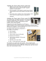
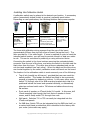
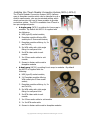
2Touch 2150 series
Interactive Whiteboard
Installation Guide
Revised 30 November 2010
This Installation Guide is intended for technicians installing a 2Touch board onto a flat
wall. It does not include the information required to adjust the 2Touch board’s optical
system for best performance. This is the subject of a separate document.
CAUTION: Utilities and procedures referred to in this manual change the configuration of
the whiteboard’s on-board processor. If these utilities are used incorrectly, the
whiteboard will not perform as designed, and may not function at all.
Please ensure that any access to these utilities is only by personnel trained and authorised
by 2Touch distributors. Always ensure that a backup copy is taken of the existing onboard configuration file before any changes are made.
Copyright 2Touch Technologies Limited 2007-2008. All rights reserved.
Congratulations !
Congratulations on your purchase of a 2Touch interactive whiteboard. We
believe we have an extraordinary solution, and we are committed to ensuring
that you enjoy all of the benefits it can offer.
We are very proud of our product, and welcome your feedback on how we
can keep improving it. Please contact me personally with your suggestions:
Pablo Garcia
Director
[email protected]
Mobile: +64-21-664-674
Toll free NZ: 0800-2-2TOUCH
(0800-2-286824)
Toll free Australia: 1800-246-808
2Touch News
Even if you have no specific feedback to offer, your contact will always be
welcome if only to register your name as a user of 2Touch boards. We will
then be able to keep you informed of new developments, of where to
download various software utilities, and of news relating to uses of the
boards.
If you would like to register to receive our newsletter, let us know by email.
Make sure you tell us the name and contact details of your organisation, and
your role – if a teacher, what subject(s) and year(s) you teach.
CONTENTS OF THIS INSTALATION MANUAL
On Delivery ...................................................................................................................4
Handling your 2Touch Board..................................................................................4
Delivery check list ....................................................................................................4
Accessories for your 2Touch Board.......................................................................5
Installation ....................................................................................................................6
Installation skills.......................................................................................................6
Preparing for the installation..................................................................................6
Suggested tools and fittings...............................................................................6
Additional Software Utilities................................................................................7
Removing your 2Touch Board from the packaging ............................................8
Choosing the IWB location .....................................................................................8
Height of the IWB ....................................................................................................9
Preparing the installation site ................................................................................9
Installing your 2Touch Board on the wall ..........................................................12
Configuring the 2Touch Board to suit multiple platforms................................13
Installing the 2Touch USB Hub............................................................................13
Installing a Cat5 extender with a 2Touch IWB .................................................14
Installing the 2Touch Audio (2Touch model 014) ............................................15
Installing the 2Touch Audio (2Touch model 015) ............................................15
Installing the Calibration Switch ..........................................................................16
Installing the Epson EB450 Projector with a 2Touch IWB ..............................17
Installing the 2Touch Modular Connection System (MCS-1, MCS-2).............18
Final checks: ...........................................................................................................20
Registering your 2Touch Interactive Whiteboard .................................................21
Using the 2Touch Board ...........................................................................................22
Switching On...........................................................................................................22
Calibrating ...............................................................................................................22
Using your 2Touch board as a mouse:...............................................................23
Multi touch gestures on the 2Touch Board: ......................................................23
Caring for and Cleaning your 2Touch Interactive Whiteboard ......................24
User Software .............................................................................................................25
2Touch Workbook ..................................................................................................25
Wordwall..................................................................................................................25
Support Contacts........................................................................................................26
Copyright 2Touch Technologies Limited 2007-2008. All rights reserved.
On Delivery
Handling your 2Touch Board
Always keep your 2Touch board right way up. The cameras are
located at the top corners of the board. Placing the board
upside down may damage or affect the camera settings.
Do not store your 2Touch board horizontally or even on a
significant lean, for more than a few minutes. Doing so can
cause bending of the board under it’s own weight, resulting in
deterioration of its performance.
Delivery check list
On receipt of your 2Touch board, please check the following:
Packaging is in good condition, without stains, water marks, tears or
rips.
There is no evidence of the packaging or its contents being transported
or stored lying on it’s side.
There is no evidence of the packaging or board being dragged on one
corner or one edge.
There is no evidence of impact damage or of weight having been
applied to the package or board.
On removal of the whiteboard, ensure that the whiteboard surface is
flat. There should be no visible deviation from flatness on the
whiteboard surface.
The accessory items (see below) are supplied.
If you are concerned with any of the above delivery and packaging related
issues, please contact us immediately.
Copyright 2Touch Technologies Limited 2007-2008. All rights reserved.
Accessories for your 2Touch Board
Accompanying your 2Touch board is a wall mount kit containing four
aluminium angle brackets and fasteners to secure these to the wall.
If you have purchased the board is part of a “ready to install” pack, then the
following items are also included in the package:
Epson EB450We
Powered USB Hub
Epson ultra short throw & bracket, 3000 lumens
Powered 4 port USB hub
2T_MCS_1
Single gang Modular Connector System: fits three
snap-in modules (1 x USB-B, 1 x RCA-1, 1 x
VGA+3.5mm). Includes pre-terminated cables fixing
direct to faceplate: 5m VGA Cable; 5m RCA video;
3m 3.5mm Stereo mini; USB.
2T_Audio015
Wall Mounted Speakers with 30 Watt room amplifier.
One"active" speaker and one "passive". 2 audio
inputs. Wired remote volume control - wall mounted.
Depending on the order, various package upgrade options are available:
2T_MCS_1 to 2T_MCS_2
2T_Audio015 to
2T_Audio014
Powered Hub to Cat5USBXtn
Upgrade connector system to dual gang
Upgrade speaker system to whiteboard speakers
Upgrade usb connectivity solution to Cat5
Copyright 2Touch Technologies Limited 2007-2008. All rights reserved.
Installation
Installation skills
Qualified technicians (“2Touch Certified Installers”) are trained in the
installation of 2Touch devices, and to use specialised utilities to monitor
optical performance of the unit during the installation and thus ensure optimal
results. For this reason we can only provide help desk support for installations
performed or signed off by 2Touch Certified Installers.
Where a customer elects to “self-install” a 2Touch board, or use a person who
is not a 2Touch Certified Installer to install a board, we advise careful study of
this manual. It is also strongly recommended that a 2Touch Certified Installer
be contracted to at least provide a final inspection review, to confirm that the
installation work has been performed correctly and that the device is working
as intended.
Installers wanting to become 2Touch Certified Installers are invited to apply
by email to [email protected].
Preparing for the installation
Optical systems rely on flat surfaces in order to deliver accurate and
consistent touch sensitivity.
It is vital that the wall onto which your 2Touch board is installed is absolutely
flat. If it is not, you will need to provide spacing such that the board is
absolutely flat both longitudinally and vertically. In particular, take care when
mounting the board to ensure that it does not bend or distort in any direction,
while hanging it onto the wall.
The 2Touch 2150 IWB is powered through the USB connection. This may be
supported by a powered USB hub.
Use only “passive” USB cable extenders if extension is needed between the
board and the USB hub or wall panel. Your AV or IT professional can advise
on alternatives such as cabling through Cat5 or using serial cabling.
The board is supplied with 1.2 m of USB cable terminating with a type A USB
plug. This is a fly lead emerging from the top left rear of the board. An
additional cabling loom provides wiring for an optional calibration switch.
Suggested tools and fittings
Selected fasteners (to secure the brackets against the wall, and perhaps also
to secure projector onto wall). In the case of the 2Touch IWB provide for
minimum of five securing points on the bottom of the board and three at the
top, ie minimum of eight fasteners. Be aware that the board’s weight itself is
taken mostly through the lower fasteners, and the top fasteners are designed
to prevent the board from distorting and maintain the alignment of the
corners. Three types of fasteners should be considered:
•
Plasterboard – wall anchors & wall mates
Copyright 2Touch Technologies Limited 2007-2008. All rights reserved.
•
Concrete – wall mates + screws
•
Timber / MDF - screws
NOTE: when applying fasteners to support projectors on the wall, be aware of
the substantial turning moment imposed by the cantilever of the projector.
This imposes a strong tensile load on the upper mount fastenings. Wallmates
(see left image in table below) do no suffice as they do not provide a
sufficient tensile fastening to support the cantilever moment from the
projector mount (they rely purely on the screw’s bearing area under tension).
However, “Togglemates” or hollow wall anchors (see right images) are more
suitable and provide better tensile support as they both provide a toggle
which expands behind the wall to provide a larger and thus more effective
bearing area under tensile loads.
Wallmate
Hollow wall anchors
Additional cabling provisions
•
USB cable extension (USB hub input to wall panel location)
•
USB cable extension (if usb hub to be located on right side of IWB)
•
USB A(male)-B(male) to supply hub within model 014 speakers (if
relevant)
•
Calibration switch, twin core cable to extend, and connector block
Suggested Tools:
•
Hand tools: Box cutter / stanley knife; wire cutters; pliers;
screwdrivers; allen key set.
•
Electric drill & driver (with hammer function); set of drill bits including
concrete drill bit; array of driver bits and drill bits
•
Soldering iron (to solder calibration switch)
•
Consumables: insulation tape; canvas backed (“duct”) tape; cable ties;
solder; Tek screws; connector / terminal blocks
•
For rare on-site camera adjustments: 1.3mm allen key; Locktite; drill
bit (to drill out rivets)
Additional Software Utilities
An accredited 2Touch technician will use either USB_Settings or USBConfig
software utilities to ensure satisfactory performance after installation. The
process of using these tools to analyse and optimise the performance of the
Copyright 2Touch Technologies Limited 2007-2008. All rights reserved.
optics system requires training and experience and this subject is not included
in this Guide.
Installers wanting to become 2Touch Certified Installers are invited to apply
by email to [email protected].
Removing your 2Touch Board from the packaging
The carton packaging comprises of an outer two-piece wrap plus top and
bottom trays. The board is supported within the trays by carton forms and
blocks. The wrap provides exterior protection during transport, as well as a
convenient hand-grip at each end of the package. The package is strapped
together in three locations along the length of the board, and stapled to the
trays.
Unpacking the board requires keeping the board supported by cutting the
straps, lifting the top tray off, removing the wraps and finally, lifting the unit
away from the lower tray.
Please check the package carefully prior to opening for any signs of
mishandling in transit or in storage, especially including tears, abrasions,
evidence of water damage. Report any observed damage to
[email protected] taking care to note the board’s serial number (this is
displayed on an exterior label on the pack).
Choosing the IWB location
We strongly recommend that installers should in every case draw the
anticipated location of the IWB, projector, audio components, cabling and
faceplate on a diagram of the room layout, and that this must be validated
with the customer before the installation proceeds. Factors to be considered
include the following:
Impact of Light:
Be aware of the effect of bright light from windows (or artificial lights) on the
visibility of the projected image. As a general rule, place the IWB as far as
possible from windows, especially those facing west or north. In cases where
light effects are unavoidable, ensure that they can be controlled using blinds
and curtains.
Proximity to Heaters:
Be aware that heaters require clear air space for ventilation and heat
dispersion. The 2Touch IWB should not be mounted closer than 200mm
above a heater. Any other associated items (such as connection panels) must
be located no closer than 1m to heaters.
Proximity to Furniture:
Be aware that effective use of an IWB requires freedom of movement in front
of the IWB and on each side of it.
Specifically, users will need to be able to stand on either side of the IWB,
facing the class, and be able to touch the IWB with an outstretched arm,
Copyright 2Touch Technologies Limited 2007-2008. All rights reserved.
without feeling impaired by furniture or other
items. We suggest that the user should be able
occupy a standing area on each side of the IWB
being no less than 500mm wide.
Height of the IWB
We recommend a standard placement of the IWB
such that the lower edge of the IWB is 900mm
above the floor, as most appropriate for adult
users. This will place key controls at the top of
the projected image, at a height of approximately
2.05m which is comfortably within reach for users
over 1.6m in height.
In some cases, users will request a higher placement of the IWB to enable an
audience a better view of the projected image. In such cases, the user must
be made aware of the difficulty of reaching controls in the top part of the
projected area. One common solution to this problem is the use of a platform
on which the user stands in front of the audience. In such a case, be sure to
consider the risk of users falling from the platform when working at one side
of the IWB, this being a frequent requirement.
Naturally, IWB’s placed in classrooms where smaller (younger) users need to
share access to the IWB with an adult teacher, requires lower placement.
Typically, a “new entrants” setting introducing users of 5 to 7 years old will
require the board to be placed at around 400mm from the floor. These
younger users will still require the assistance of an adult to access the
controls near the top of the display. Be aware also, that a head-contact
hazard may arise with lowering the projector to suit a low placed IWB. This
will require additional provision for hazard management.
Preparing the installation site
Typically, connections are required in three zones near the iwb:
A. Power and video cabling is to be provided to the projector location
B. A powered USB hub is connected to the board and itself required 230v
mains power, as well as receiving a USB feed from the wall connection
point C (below). Typically, this zone also includes provision for audio
connections in the case of the 2Touch model 014 audio solution.
C. A wall connection panel provides users with the facility to connect:
a. Video to the projector (usually VGA)
b. USB to the 2Touch IWB
c. Audio to the audio system (usually 3.5mm audio jack)
Copyright 2Touch Technologies Limited 2007-2008. All rights reserved.
In the following diagram, power and connector requirements are identified for
these three zones. The diagram displays the combination of a 2Touch IWB,
the Epson EB450W projector, and the 2Touch 014 audio solution.
Note that the wall panel can be located on either side of the board, however
installers must be aware of the consequences of this decision on the length of
USB cabling from the board via the USB hub to the wall panel (typically, an
extra 2m USB extension cable will be required if the wall panel is positioned
on the right hand side of the board).
Note also that in the case of the 2Touch 015 audio solution being used, there
is no provision of USB ports on the front of the speakers. Therefore the
placement and connection of the USB hub is then entirely independent of the
audio solution, and the 2TAudio_015 speakers can be mounted completely
separately from the rest of the package, providing only for the relevant power
and audio feeds to that system. In these cases, the USB hub is most typically
secured behind the 2Touch board but at one edge, such that it can readily be
accessed for servicing purposes, and the hub is powered from a GPO typically
located behind the board or immediately below it.
The next diagram outlines the provision of cabling:
•
VGA and other video cabling from the projector to the wall panel;
•
Audio cabling from the audio solution to the wall panel, and between
the two speakers;
Copyright 2Touch Technologies Limited 2007-2008. All rights reserved.
•
USB cabling from the IWB to the powered USB hub, and from the
powered USB hub to the wall panel;
•
Calibration switch cabling from the IWB to the desired location of the
calibration switch.
Copyright 2Touch Technologies Limited 2007-2008. All rights reserved.
Installing your 2Touch Board on the wall
Before installation, USB (and calibration switch if appropriate) connectors
must be reticulated to a suitable position so that they can be connected to the
wiring loom once the board is in place. Any usb hub or converters will need
to be supported or mounted to permit connection to the board, to the wall
panel and to their low voltage supply cables.
The board is supplied with six short lengths of
aluminium angle (40x40x3mm). These are to
secure the board to the wall around the
perimeter, one near each corner of the board
and two at mid length.
The preferred procedure is as follows:
1. Attach 40x40x3mm angle brackets to
wall: Fit two bottom outer bracket(s)
first to the required height. Lift the
board onto these and hold it temporarily
while marking off centre and top corner
bracket positions onto wall. For the top
corners, ensure support to within 70mm
of camera corners of board. Now lower the board to the ground, and
fit the remaining brackets in place.
2. Lift board into the tight space between the fitted brackets, and support
it in place while ensuring the cabling runs clear behind board:
a. Existing USB cable from board runs to USB hub where located at
left edge of board (if hub to be located at right edge of board
will need additional 1.2m USB type A-type A male-female
extension cable)
b. Calibration pair to switch location. May require extension and
connector block (or solder)
c. If speakers (model 014) next to IWB are required, ensure
cabling between speakers is run behind board
Secure the board in place through one top bracket, using a tek screw
into the board frame note following caution). This is to hold the IWB
in place through the next step.
IMPORTANT NOTE - Take care in placing tek
screws to avoid cameras and electronics (see
sketch at right). So long as screws are
contained to the 50% of the outer frame section
closest to the wall (or rear of whiteboard), any
over-run of the screw will penetrate the board
substrate rather than the electronics or optics
components located in the touch frame. On the
2150 model of 2Touch IWB, electronics are
included only in the top (horizontal) rail, and not
on the other three sides of the board.
Copyright 2Touch Technologies Limited 2007-2008. All rights reserved.
3. Connect the board to your computer. Using USBSettings software,
check the camera traces. Work around the board, observing camera
outputs, and ensure that board is level and flat while applying the
remaining screws to secure the board to the brackets at each corner.
Secure top & bottom edges of board with total five screws (ie three
additional) each edge.
Configuring the 2Touch Board to suit multiple platforms
By default, every 2Touch board is pre-configured for optimum performance
using Windows 7. Where a site needs cross-platform support or needs to
support a different platform such as Apple Macintosh or Linux, the installer
will need to change the default configuration of the board to permit this.
Under the mouse tab in the USB Config utility, select “on” the “Mac
compatibility” field. This will revert the board to support multiple platforms on
a plug-and-play (ie no additional drivers) basis, however it will limit the board
from supporting the standard multi-touch functions under Windows 7.
Installing the 2Touch USB Hub
A four-port USB 2.0 powered hub is available for use
with 2Touch IWB’s. This unit and its power supply have
been extensively tested for compatibility.
1. The USB hub may be placed within cavity at base
of speaker model 014 (if applicable) by using a
right angle power connector (not supplied).
Otherwise, place the USB hub behind the edge of
board in such a position that it may be accessed
later if required.
2. Power connection to USB hub is required.
Optimally, a GPO can be placed behind the board
to furnish this provided that sufficient gap is available between the
board and the wall to accommodate the thickness of the supplied
power pack (50mm). Otherwise, a GPO will need to be provided within
900mm of the hub.
3. USB connection to IWB: The USB flylead on the 2Touch IWB is 1.6m
long with a type A plug, and emerges from a position 300mm from the
top left corner of the IWB. This flylead will reach a hub placed
anywhere on the left edge of the IWB; however a 2m USB extension
cable will be required to reach a hub position on the right edge of the
IWB.
4. USB connection toward computer: Depending on the placement of the
hub, and on the wall panel location, an additional USB type A male –
type A female extension may be required to run from the hub to the
wall panel location.
Copyright 2Touch Technologies Limited 2007-2008. All rights reserved.
5. USB type A cable from board into hub outlet (note additional USB
extension needed if port is placed on right side of board)
6. If 2Touch model 014 speakers supplied, then a USB type A male to
USB type B male cable will be required to connect from a hub outlet
port, to the USB input port on the active speaker. This permits the
dual USB ports on front of speakers to be available to the user.
Installing a Cat5 extender with a 2Touch IWB
In some cases, the wall panel location may be too far away from the IWB to
practically extend the USB cable using conventional USB extenders. In such a
case, the recommended practice is to use a USB-to-Cat5 extension solution.
This converts the USB signal from the board to a format compatible for
transport of Cat5 cable. At the wall panel end, the signal is reconverted to
USB, and the USB is then terminated to the wall
panel in the normal fashion.
The image at right illustrates a Lindy USB-toCat5 extension solution.
Note that the use of an external power supply is
essential to the functioning of the IWB, as the
Cat5 signal itself will no longer supply the
required current to drive the USB device. The
power supply must be connected to the
conversion unit at the IWB end, not at the wall
panel end.
If the standard Lindy power supply is not used with the Lindy USB-to-Cat5
extension solution, then alternates may be acceptable provided that they
supply 5volts and at least 500mA, and that they incorporate effective voltage
regulation.
A USB-to-Cat5 extension solution might also be used in combination with a
powered USB Hub. The IWB’s USB fly lead is connected in the usual way to
one of the USB hub outlets. The input side of the hub (ie computer end) is
connected to the USB-to-Cat5 solution. At the remote (wall panel) end, the
Cat5 is again converted back to USB and connected to the wall panel in the
usual way. In this situation, the use of a power supply for the USB-to-Cat5
solution is not required since the IWB is independently powered by the
powered hub (which has its own power supply).
Cautionary note: Use of power supplies with inadequate voltage regulation
can cause serious damage to the IWB’s internal circuitry. Except where the
powered USB hub or the Cat5-USB conversion solution (including the power
supply) used in the installation has been supplied by 2Touch Technologies Ltd
and / or Interactive Whiteboards Australia Pty Ltd, damage to the 2Touch
IWB caused by fluctuations in voltage on the USB line cannot be covered by
warranty.
Copyright 2Touch Technologies Limited 2007-2008. All rights reserved.
Installing the 2Touch Audio (2Touch model 014)
1. Position anchor posts: 67mm from edge of board;
265mm down from top edge of board. Suspend
speakers on anchor posts.
2. Line up speakers to be parallel to vertical edge of board.
Position black screws to top brackets to prevent speaker
twist.
3. Note cavity recess in bottom rear of each speaker, which
can be used to conceal wiring and components if
necessary.
Installing the 2Touch Audio (2Touch model 015)
The 2Touch Audio_015 speaker assembly is the standard
assembly included with 2Touch packages. It consists of
an active (powered) speaker incorporating a stereo
amplifier, plus a passive speaker.
Compared to the model 014 solution, the 015 uses a
smaller enclosure; has no USB connectivity, and features additional audio
input on the front panel. A wired remote mounted volume scroll permits the
015 speaker assemblies to be mounted high.
The image at left outlines the components in
the 2TAudio_015 assembly….:
A. Active speaker
B. Passive speaker
C. Wired remote volume & off-switch
D. Brackets set & fasteners
E. Cable between speakers (3.5mm jack
one end only)
F. RCA-RCA stereo input cable
G. RCA – 3.5mm audio stereo input cable
Two brackets are supplied with each speaker. These (combined with
appropriate wall anchors where necessary) support the 015 speakers on the
wall, usually well away from the IWB itself, and generally high above areas
where user contact might be likely.
Copyright 2Touch Technologies Limited 2007-2008. All rights reserved.
Installing the Calibration Switch
A calibration switch may be placed at the desired user location. A momentary
action (momentarily closed) switch is required, preferably push button.
Depending on user preferences, the following switches have proven popular:
Jaycar SP0716
Jaycar SP0710
Jaycar SP0755
Jaycar SP0780
Pushbutton PUSHON MOMENTARY
SPST RED
ACTUATOR
Rated 3A 250V
AC.Mounting hole
12mm
Red Miniature
Pushbutton SPST Momentary
Action
Push On
Red Button125V 3A
rating
Metal Momentary SPST
- Silver Metal body
- Rated 8A @ 125VAC or 4A
VAC
- Momentary action SPST
- 19mm mounting hole
- Screw terminal termination
Bell Pushbutton
N.O. contacts- Size
60(L) x 32(W) x
12(D)mm.- Fawn
in colour.
The loom with calibration wiring emerges from the rear of the board
approximately 800mm from top left corner of board (facing the front). The
loom provides for 1.2m cable length. If more is required in order to reach the
intended switch location, you will need to provide a length of dual-core cable
to suit. This can be connected by soldering or using connector blocks.
Connecting the switch to the loom involves removing the redundant plastic
connector from the end of the loom, and wiring the switch to the blue and the
black wires from the loom. (The other two wires are redundant and can be
cut short and insulated from each other). When the black and the blue wires
are shorted together by the switch, calibration mode will launch on the board.
The location for the calibration switch is most commonly one of the following:
•
Top of iwb (usually top left corner), provided that user can reach the
switch position. This renders the switch less likely to be erroneously
pressed or targeted by students or visitors. In this case, either mount
switch 710 through one of the IWB mounting brackets such that it is
positioned behind the board and operated vertically, or alternatively
select an enclosed swich such s 780 above and adhere these to any
flat surface.
•
Front panel of speaker on 2Touch Audio 014 model. In this case, drill
12mm mounting hole through the front facia of speaker in lower
recess, and fit easily switch 716 through from rear.
•
Wall panel: Switches 710 or 755 can easily be integrated into the
2Touch wall panels.
•
On IWB face: Switch 755 can be integrated into the IWB trim itself, on
a custom build basis provided that this is identified to the factory with
your order (extra costs may apply).
Copyright 2Touch Technologies Limited 2007-2008. All rights reserved.
Installing the Epson EB450 Projector with a 2Touch IWB
1. Position bottom of bracket 40cm above top edge of whiteboard.
2. If image is to be placed at one edge of board, then projector bracket
centreline should be 950mm from that (outer) edge of board (see
diagram below).
3. Extend bracket to 37.5cm off wall position
4. Fit projector (remember to loosen cap screws permitting rotation
adjustment).
5. Press Num button; press 0, hold Num button down and press 0 four
times to unlock password protect on Epson projector.
6. Adjust to suit image on board – 40mm down from top of board.
a. Set Auto adjust = off
b. Set Resolution = auto
c. Set aspect = Full
d. Projector should adjust to keystone =0, medium zoom position.
Focus adjust is on slide in right hand compartment.
Copyright 2Touch Technologies Limited 2007-2008. All rights reserved.
Installing the 2Touch Modular Connection System (MCS-1, MCS-2)
The 2Touch Modular Connection System (MCS) features
snap-in faceplate modules which can be selected to suit a
client’s requirements, plus pre-terminated cabling which
simply screws into the rear of these modules to provide
connection outlets. The MCS is available from 2Touch in
two pre-configured packs:
•
A single gang (MCS-1) providing for three snap-in
modules. By default the MCS-1 is supplied with
the following:
A. USB (type B) socket module;
B. Faceplate module offering VGA
socket plus 3.5mm audio socket;
C. Faceplate modules offering 1x, 2x
and 3x RCA;
D. 5m VGA cable with right-angle
fitting for wall panel end
E. 5m RCA video cable to suit
module
F. 3m 3.5mm audio cable to suit
module
G. Screws to fasten cable ends to
faceplate modules
•
A dual-gang (MCS-2) providing for six snap-in modules. By default
the MCS-2 is supplied with the
following:
A. USB (type B) socket module;
B. 2 X Faceplate module offering
VGA socket plus 3.5mm audio
socket;
C. Faceplate modules offering 1x, 2x
and 3x RCA;
D. 5m VGA cable with right-angle
fitting for wall panel end
E. 5m RCA video cable to suit
module
F. 3m 3.5mm audio cable to suit module
G. 2 x 3m RCA audio cable
H. Screws to fasten cable ends to faceplate modules
Copyright 2Touch Technologies Limited 2007-2008. All rights reserved.
Additional or alternative snap-in modules may be supplied to
requirements from the following:
2T_MCS_blank
module - blank
2T_MCS_RCA1/2/3 Modules with 1, 2 or 3 x RCA connectors
2T_MCS_USB
module with USB-B on faceplate, USB-A behind
2T_MCS_RJ45
Module with RJ45 connector
2T_MCS_Svideo
Module with S-Video & 2x RCA connectors
Through the combination of a choice of “snap-in”
faceplate modules, plus pre-terminated cabling
which connects to these using the supplied screws,
the installer’s task of preparing and connecting the
faceplate is made extremely quick and simple.
The pre-terminated VGA cable is attached through
the front of the faceplate using the supplied screws
which in turn permit user cabling to be secured to
the front of the faceplate. Other pre-terminated
cabling (RCA and 3.5mm audio) are attached to
the ear of the faceplates using attached screws.
A large slide on one side of the connector box can be removed for easy side
access by cables or ducting. Additional holes are available through press-outs
in the plastic container both at rear and on sides.
Copyright 2Touch Technologies Limited 2007-2008. All rights reserved.
Final checks:
The following final checks should be performed on site for every board:
-
Camera signals are strong throughout (particularly observe signal
strength at and near opposing diagonal corner, and opposing camera);
-
each camera trace provides strong shadow depth throughout the
monitored range;
-
check opening and closing aperatures ;
-
check top straightening performance and adjust as required;
-
Calibration performs correctly;
-
Performance is accurate, responsive and comprehensive. Using
2Touch Workbook, rapidly draw dense lines on screen to ensure that
there are no “dead spots” and that responsiveness is good. Draw fast
tight circles all over the surface in a continuous stream (not “touchoff”), to ensure that circles and curves are smooth and that there are
no gaps in line drawing.
-
One all above are checked satisfactory, save the board’s configuration
file (.v299) and a snapshot of the camera traces showing camera
settings as well. These are both to be saved using the following file
name nomenclature:
SerialNumber_ReversedDateYYMMDD_location
For example: 123456_20101005_Pablo’sOffice
-
These files are to be uploaded by Dealer onto the board’s record on
Tracker.
Copyright 2Touch Technologies Limited 2007-2008. All rights reserved.
Registering your 2Touch Interactive Whiteboard
2Touch Certified Installers are required to record the following details for
every installation, into the secure 2Touch Tracker on-line product database:
•
Serial number of board
•
Customer details
•
Location of board
•
Screen capture of camera scope from USB Settings
•
Saved .v299 board configuration file after install.
If your board is not being installed by a 2Touch Certified Installer, then as a
minimum please register your 2Touch device by advising the following to
[email protected]:
-
Serial number (identified from USBSettings software, or advised by
your Dealer)
-
Location of board (room & building details)
-
Organisation name, Contact name, Telephone and Email
-
Dealer from which you purchased the 2Touch IWB
The above information is essential to activate your copy of the
bundled software.
Copyright 2Touch Technologies Limited 2007-2008. All rights reserved.
Using the 2Touch Board
Switching On
Connect the cables and switch on power to any USB peripherals prior to
connecting the USB cable to the 2Touch board. Connect and power up the
computer and projector.
The computer then automatically detects
the USB device and, after a short pause,
displays a series of messages on screen.
(The computer only displays this message
the first time you plug in the USB cable.
The next time you plug in the cable, the
computer will be already configured for the device.)
Once the computer has established USB communications with the touch
panel, provided that the buzzer has been left enabled on the board (default
setting), you will hear minute “clicks” on touching the surface. This clicks can
be disabled if required, by your 2Touch Certified Installer. However user
feedback indicates that users prefer this unintrusive auditory feedback from
the board.
Calibrating
Calibrating the 2Touch board is the process of ensuring that your touch
location on the surface aligns accurately with the projected mouse cursor
position.
To launch calibration mode on the board, just press the calibration button.
You can cancel calibration mode and return to normal use mode, by pressing
the button again. Another way of launching calibration (available for Windows
computers only) is to press the “scroll-lock” button six times in succession.
Upon launching calibration, the mouse cursor on the projected image will
move to the first (upper left) calibration point. Holding your finger
perpendicular to the surface, and taking care that there are no items of
clothing or other part of your body touching the surface, press your finger on
the tip of the cursor and hold it there for at least 3 seconds until you have
heard the confirmation tone which signals that you can move on to the next
calibration point.
Upon lifting your finger off the surface, the cursor will automatically move to
the next, second position (upper right). Repeat the procedure for this, and
two further calibration positions (lower right and lower left respectively).
Upon completion of the fourth calibration position, the board will return to
normal use mode. Check that touch tracking is perfectly accurate throughout
the touchable area. If it is not, repeat the calibration process, allowing for
more time at each point and taking care to ensure that the calibration point is
being touched accurately.
Copyright 2Touch Technologies Limited 2007-2008. All rights reserved.
Using your 2Touch board as a mouse:
Upon connecting any computer to the 2Touch interactive whiteboard, single
touch mouse functionality is enabled instantly (without the need for any
additional software). The standard mouse controls are performed as follows
on the surface of the board:
A touch is a leftmouse-click
Touch-and-hold is a
right-mouse-click
Touch-and-drag
Multi touch gestures on the 2Touch Board:
If using the 2Touch board on a computer with Windows 7, the board surface
can be used with 2Touch gestures to perform the following basic functions in
any compliant Windows environment:
Pinch to scale
2 finger rotate
2 finger scroll
Select an object (for
example, a window) with one
finger; with a second finger
then touch and drag towards
or away from the first finger
to make the object smaller or
larger.
In compliant software
applications: a first touch
and hold determines the
centre of rotation, while
the arc of the second
touch determines the angle
and direction of rotation.
Inside of any Window,
dragging down or up with
both fingers
simultaneously will invoke
the down or up scroll. This
is particularly useful on a
whiteboard!
Note: to use Windows 7 gestures, the user must have the multi touch driver
installed (available from www.twotouch.com), and must also have gestures
enabled in Windows 7.
Copyright 2Touch Technologies Limited 2007-2008. All rights reserved.
Caring for and Cleaning
your 2Touch Interactive Whiteboard
Cleaning the Whiteboard surface: The 2Touch IWB uses a porcelain steel
whiteboard surface. Porcelain on steel whiteboard surfaces deliver the best
performance in terms of eraseability, ease of cleaning and resistance to scratches and
stains.
The porcelain enamel finish is similar to a tough glass coating on the steel and can be
cleaned with any commercially available glass or whiteboard cleaner. It is important
to remove any glass cleaner residue from the surface with soap and clean water (then
dry with a clean cloth) to prevent any reactions between these residues and the
solvents or inks in dry erase markers.
Frequently cleaned writing surfaces are easier to maintain. When a surface becomes
heavily soiled with old ink, this soil serves to “catch” subsequent ink writing making
it ever harder to erase and leaving annoying smears and ghost traces on the surface.
Dry erase inks left on a whiteboard for weeks or months may require cleaning with a
mild solvent to fully remove old stains and provide a clean board surface for future
good service. Solvents based on isopropyl alcohol are best, and are widely used in
commercially available whiteboard cleaning fluids. Rinse the surface afterwards with
water and dry thoroughly for best results.
Be aware that not all marker brands achieve the same “eraseability” performance. In
particular, low odour markers can be harder to dry erase effectively.
Permanent markers can be used on porcelain enamelled writing surfaces and the
image removed with almost any mild solvent such as alcohol – again the solvent
residue needs to be removed with soap and water. Alternatively, just write over the
permanent marker ink, using a dry-erase marker. Erase off, and repeat as often as
necessary to remove all residual staining.
Keep edges clean: The inside (black) edges of your 2Touch IWB
incorporate reflective tape elements which are part of the touch
solution.
At least monthly (and preferably weekly) these edges should
be wiped clean with a soft dry cloth, to remove any dust and
particles of marker residue which might have deposited on
them. If this is not done, accumulated dust and dirt may eventually affect touch
accuracy and performance.
Copyright 2Touch Technologies Limited 2007-2008. All rights reserved.
User Software
2Touch Workbook
Having purchased a 2Touch board, your organization is automatically entitled
to a site-wide license for this powerful white-boarding software.
•
2Touch Workbook can be downloaded from http://update.twotouch.com.
This provides a 30 day free trial of a diminished function version. This
converts instantly into the fully featured, fully licensed software upon
activation. To activate, you must provide a valid 2Touch Customer Key.
•
The “2Touch Customer Key”, unique to your organization, can be provided
to you by your 2Touch Authorised Dealer. This Customer Key is credited
with site-wide licensing for Workbook software once the serial numbers for
your 2Touch boards have been communicated by the Dealer to 2Touch.
•
During “activation”, the software communicates on-line with a licensing
tool which validates the Customer Key data. Activation is a single click
process once the Customer Key has been entered.
•
An in-depth user manual as well as an administrator’s guide are available
for 2Touch Workbook, from www.twotouch.com. There is also a range of
video tutorials in the use of the software.
Wordwall
Where a 2Touch interactive whiteboard is purchased by either a primary or a
secondary school, one concurrent-user license of the innovative Wordwall
teaching and collaboration software is available for every 2Touch board
purchased.
•
Wordwall software can be downloaded from www.wordwallweb.com.
•
To obtain (or update concurrency for) the Wordwall license key, please
send the following details to [email protected].
o your organization name
o postal code
o contact detail (name and email),
o the number of 2Touch interactive whiteboards purchased by
your organization since January 2010
•
An in-depth user manual is available for Wordwall from
www.wordwallweb.com. There is also an excellent Flash training and
demonstration resource on this site.
A Wordwall License Key is then be generated and sent to the email provided.
The Wordwall License Key is used for all implementations of Wordwall
software at your site, and can be updated for as many concurrent users as
appropriate.
Copyright 2Touch Technologies Limited 2007-2008. All rights reserved.
Support Contacts
First line of support:
Your first line for support is the 2Touch Authorised Dealer which supplied your
2Touch board. A complete list of all 2Touch Authorised Dealers and their
contact details is available from www.twotouch.com.
Second line of support:
Where dealers are unable to assist, technical support for 2Touch IWB
hardware and installations may next be obtained by telephone or email from
the national manufacturer & distributors, as follows:
Australia: Interactive Whiteboards Australia Pty Ltd
03-9840-4700, 1800-246-808
[email protected]
New Zealand: 2Touch Technologies Ltd
09-440-9988, 0800-2-2TOUCH (0800-2-286824)
[email protected]
Before calling:
When calling for support, regardless of the nature of the issue remember that
no support can be provided without the serial number of the affected 2Touch
interactive whiteboard. Please ensure therefore that you have the serial
number of the affected 2Touch board to hand before you call. This will allow
the technician taking your call to access that unit’s factory history and any
records available, and will also enable the call to be logged and any actions
arising to be assigned.
Software support:
Software support for 2Touch Workbook and Wordwall is available directly
from the software author by email only: [email protected].
Copyright 2Touch Technologies Limited 2007-2008. All rights reserved.