1
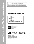
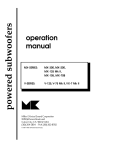
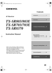
® THX powered subwoofers operation manual MX-5000THX Mk II MX-350THX Miller & Kreisel Sound Corporation 10391 Jefferson Boulevard Culver City, CA 90232 USA (310) 204-2854 FAX (310) 202-8782 © 1997 MILLER & KREISEL SOUND CORP. Manufactured under license from Lucasfilm Ltd. Lucasfilm and THX are registered trademarks of Lucasfilm Ltd. THX subwoofers page 2 TABLE OF CONTENTS 1. 2. 3. 4. 5. 6. 7. 8. 9. 10. 11. 12. 13. SAFETY INSTRUCTIONS ................................................................................................ 3 INTRODUCTION .............................................................................................................. 4 WHERE TO PLACE YOUR SUBWOOFER ..................................................................... 4 OPERATION WITH THX COMPONENTS........................................................................ 4 CONNECTING THE SUBWOOFER TO A THX CONTROLLER ........................................................... 4 TESTING THE SUBWOOFER (THX) .......................................................................................................... 6 CALIBRATING THE SUBWOOFER (THX) ...................................................................... 6 OPERATION OF THE "LOW PASS FILTER" AND "BASS LEVEL" SWITCHES ....................................... 6 OPERATION OF THE "BASS EQ" SWITCH (THX) .................................................................................... 6 SETTING SUBWOOFER LEVEL (THX) ...................................................................................................... 7 USING TWO SUBWOOFERS (THX) .......................................................................................................... 7 OPERATION WITH A NON-THX PROCESSOR .............................................................. 7 OPERATION OF THE "LOW PASS FILTER" SWITCH ............................................................................. 7 OPERATION OF THE "BASS EQ" SWITCH ............................................................................................... 8 OPERATION OF THE THE "BASS LEVEL" SWITCH................................................................................. 8 WIRING WITH A NON-THX PROCESSOR OR PREAMP .......................................................................... 8 USING THE SUBWOOFER WITH THE M&K HP-80 OR VF-80 HIGH-PASS FILTERS ......................... 10 TESTING THE SUBWOOFER (NON-THX) .............................................................................................. 11 SETTING SUBWOOFER LEVEL (NON-THX).......................................................................................... 11 USING TWO SUBWOOFERS (NON-THX) .............................................................................................. 11 SATELLITE/SUBWOOFER PHASING TEST ................................................................ 12 FINE-TUNING THE PLACEMENT OF YOUR SUBWOOFER ....................................... 13 SPECIAL METHOD FOR PLACING THE SUBWOOFER ........................................................................ 13 USE OF SPIKED FEET ..................................................................................................14 TROUBLESHOOTING ................................................................................................... 14 IF YOU NEED TO REPLACE THE EXTERNAL FUSE ............................................................................ 15 IF YOU NEED SERVICE ................................................................................................ 16 SPECIFICATIONS .......................................................................................................... 16 CABINET MAINTENANCE ............................................................................................ 16 WIRING DIAGRAMS FIGURE 1 FIGURE 2 FIGURE 3 FIGURE 4 FIGURE 5 FIGURE 6 ONE SUBWOOFER TO A THX CONTROLLER.................................................... 5 TWO SUBWOOFERS TO A THX CONTROLLER................................................. 5 ONE SUBWOOFER TO A SURROUND CONTROLLER (NON-THX) .................. 9 TWO SUBWOOFERS TO A SURROUND CONTROLLER (NON-THX) ............... 9 ONE SUBWOOFER TO AN AMP OR PREAMP (NON-THX) .............................. 10 TWO SUBWOOFERS TO AN AMP OR PREAMP (NON-THX) ........................... 10 THX subwoofers page 3 CAUTION RISK OF ELECTRIC SHOCK DO NOT OPEN The lightning flash with arrowhead, within an equilateral triangle, is intended to alert the user of the presence of uninsulated "dangerous voltage" within the product's enclosure that may be of sufficient magnitude to constitute a risk of electric shock to persons. CAUTION: TO PREVENT THE RISK OF ELECTRIC SHOCK, DO NOT REMOVE COVER (OR BACK). NO USER-SERVICEABLE PARTS INSIDE. REFER SERVICING TO QUALIFIED SERVICE PERSONNEL. The exclamation point within an equilateral triangle is intended to alert the user of the presence of important operating and maintenance (servicing) instructions in the literature accompanying the appliance. 1. SAFETY INSTRUCTIONS 1. 2. READ INSTRUCTIONS - All safety and operating instructions should be read before this product is operated. 1 RETAIN INSTRUCTIONS - The safety and operating instructions should be retained for future reference. 3. HEED WARNINGS - All warnings on this product and in the operating instructions should be adhered to. 4. FOLLOW INSTRUCTIONS - All operating and use instructions should be followed. 5. ATTACHMENTS - Do not use attachments not recommended by the product manufacturer as they may cause hazards. 6. WATER AND MOISTURE - Do not use this product near water - for example, near a bath tub, wash bowl, kitchen sink, or laundry tub; in a wet basement; or near a swimming pool; and the like. 7. ACCESSORIES - Do not place this product on an unstable cart, stand, tripod, bracket, or table. The product may fall, causing serious injury to a child or adult, and serious damage to the product. Use only with accessories recommended by the manufacturer, or sold with the product. Any mounting of the product should follow the manufacturer's instructions and should use a mounting accessory recommended by the manufacturer. 8. POWER SOURCE - This product should be operated only from the type of power source indicated on the marking label. If you are unsure of the type of power supply to your home, consult your product dealer or local power company. 9. OVERLOADING - Do not overload wall outlets or extension cords as this can result in a risk of fire or electric shock. 10. LIQUID ENTRY - Never spill any liquid of any kind on the product. 11. SERVICING - Do not attempt to service this product yourself. Opening or removing covers, including any over bottom or side speaker drivers, may expose you to dangerous voltage or other hazards. Refer all service to qualified service personnel. 12. DAMAGE REQUIRING SERVICE - Unplug this product from the wall outlet and refer servicing to qualified personnel under the following conditions: a. When the power-supply cord or plug is damaged. b. If liquid has been spilled, or objects have fallen into this product. c. If the product does not operate normally by following the operating instructions. Adjust only controls that are covered by the operating instructions as an improper adjustment of other controls may result in damage and will often require extensive work by a qualified technician to restore the product to its normal operation. d. If the product has been dropped or damaged in any way. e. When the product exhibits a distinct change in performance - this indicates a need for service. 13. REPLACEMENT PARTS - When replacement parts are required, be sure the service technician has used replacement parts specified by the manufacturer or have the same characteristics as the original part. Unauthorized substitutions may result in risk of fire, electric shock, or other hazard. 14. SAFETY CHECK - Upon completion of any service or repairs to this product, ask the service technician to perform safety checks to determine that the product is in proper operating condition. 15. HEAT - This product should be situated away from heat sources such as radiators, heat registers, stoves, or other products (including amplifiers) that produce heat. THX subwoofers page 4 2. INTRODUCTION Congratulations! Your new M&K THX® subwoofer truly represents the state-of-the-art in subwoofer performance. The new dimension of deep and powerful bass it provides will both thrill and excite you. We strongly encourage you to read this owner's manual, as there is a great deal of information provided here to help you get the best possible performance. If you have any questions about your subwoofer, please contact your M&K Home THX Audio dealer, or call the M&K factory directly at (310) 204-2854, from 8:30 AM to 5:00 PM Pacific Time. We will be more than happy to help you with any question, no matter how simple or complex it may be. For more details on the installation and calibration of your Home THX Audio system, please refer to the THX Installation & Operation Manual. THIS OWNER'S MANUAL HAS TWO SETS OF SET-UP INSTRUCTIONS. ONE SET IS FOR USING THE SUBWOOFER WITH A THX CONTROLLER. THE OTHER SET IS FOR USE WITH NON-THX PROCESSORS. To operate it with a THX controller, see Section 4 below. To operate it with a non-THX controller, see Section 6 (page 7). 3. WHERE TO PLACE YOUR SUBWOOFER Your subwoofer will deliver excellent performance located virtually anywhere in your room. Unless you are next to the subwoofer, you will not hear it as a separate source of sound. In fact, its deep bass will appear to come from your other speakers. Therefore, there is no need to place your subwoofer either between your Satellite or L/C/R speakers or in any specific location in the room. You can significantly improve and fine-tune your subwoofer's performance by experimenting with its placement in the room. For more detailed placement information, please see Section 8 (page 13). Your subwoofer is magnetically shielded, so you can locate it close to a television without picture distortion occurring from magnetic deflection of the TV's electron beam. Wherever you put the subwoofer, you must allow room for ventilation of its heatsink and backplate. The subwoofer's power amplifier is mounted on the backplate, and it generates heat. Therefore: 1. Do not place the subwoofer against a wall. Leave at least 3 inches clearance for the heatsink. 2. Do not place the subwoofer close to baseboard heaters or forced air heating outlets. DO NOT PLUG THE SUBWOOFER INTO AN AC OUTLET UNTIL ALL SYSTEM WIRING IS COMPLETE 4. OPERATION WITH THX COMPONENTS CONNECTING THE SUBWOOFER TO A THX CONTROLLER The "INPUT" RCA terminals on the subwoofer connect it to the outputs of your THX controller. All of the input connections and controls for the subwoofer are located on its large metal backplate, which can be found on the back panel of the subwoofer cabinet. THX subwoofers page 5 To connect the subwoofer, run a shielded RCA - RCA interconnect cable from the SUBWOOFER OUTPUT jack on your THX controller to the "LEFT/MONO" "INPUT" jack on the subwoofer's backplate. See Figure 1 below. Some THX controllers have a pair of stereo subwoofer outputs, while others have a single mono output. Your subwoofer is compatible with both types. If your THX controller has stereo subwoofer outputs, use a stereo shielded cable, connecting it to the LEFT and RIGHT "INPUT" terminals on the subwoofer. If your THX controller has only a single mono subwoofer output, use a mono cable and connect it to the subwoofer's "LEFT/MONO" "INPUT" jack. See Figure 1 below. Do not use a Y-connector to connect the signal to both the LEFT and RIGHT inputs of the subwoofer. These inputs are summed to mono in the amplifier input stage, and if they are combined, the result will be too much gain and bass level. FIGURE 1- WIRING ONE SUBWOOFER WITH A THX CONTROLLER LOW PASS FILTER THX MODE V A R I A 06 B L E SUBWOOFER OUT NO LOW PASS FILTER 57 80 Hz 24 dB/ OCTAVE CENTER SWITCH POSITION FOR VARIABLE LOW PASS THX CONTROLLER THX RIGHT REFERENCE +3 dB THX INPUT 521 05 BASS LEVEL BASS EQ PHASE + LEFT/MONO 01 +6 dB EXTENDED VARIABLE MX-350THX POWERED SUBWOOFER Manufactured under license from Lucasfilm Ltd. Lucasfilm and THX are registered trademarks of Lucasfilm Ltd. CAUTION RISK OF ELECTRIC SHOCK DO NOT OPEN Made in U.S.A. AVIS: RISQUE DE CHOC ELECTRIQUE. NE PAS OUVRIR. CAUTION: DISCONNECT SUPPLY CORD BEFORE CHANGING FUSE. REPLACE FUSE ONLY WITH SAME TYPE. ATTENTION: DEBRANCHER AVANT DE REMPLACER LE FUSIBLE. UTILIZER UN FUSIBLE DE RECHANGE DE MEME TYPE. 120 VAC 50/60 Hz MILLER & KREISEL SOUND CORP. 10391 Jefferson Blvd Culver City, CA 90232 310/204-2854 T 6 AMP SLOW-BLOW FIGURE 2 - WIRING TWO SUBWOOFERS WITH A THX CONTROLLER use a Y-connector if your controller has only one subwoofer output jack THX CONTROLLER SUBWOOFER OUT LOW PASS FILTER THX MODE V A R I A 06 B L E NO LOW PASS FILTER 57 PHASE + 05 521 CENTER SWITCH POSITION FOR VARIABLE LOW PASS CAUTION RISK OF ELECTRIC SHOCK DO NOT OPEN BASS LEVEL BASS EQ LEFT/MONO RIGHT THX THX INPUT 01 80 Hz 24 dB/ OCTAVE LOW PASS FILTER REFERENCE +3 dB +6 dB EXTENDED VARIABLE MX-350THX POWERED SUBWOOFER THX MODE V A R I A 06 B L E Manufactured under license from Lucasfilm Ltd. Lucasfilm and THX are registered trademarks of Lucasfilm Ltd. Made in U.S.A. 05 521 CAUTION RISK OF ELECTRIC SHOCK DO NOT OPEN BASS LEVEL BASS EQ LEFT/MONO RIGHT THX THX INPUT 80 Hz 24 dB/ OCTAVE REFERENCE +3 dB +6 dB EXTENDED VARIABLE MX-350THX POWERED SUBWOOFER Manufactured under license from Lucasfilm Ltd. Lucasfilm and THX are registered trademarks of Lucasfilm Ltd. Made in U.S.A. AVIS: RISQUE DE CHOC ELECTRIQUE. NE PAS OUVRIR. CAUTION: CAUTION: DISCONNECT SUPPLY CORD BEFORE CHANGING FUSE. REPLACE FUSE ONLY WITH SAME TYPE. DISCONNECT SUPPLY CORD BEFORE CHANGING FUSE. REPLACE FUSE ONLY WITH SAME TYPE. ATTENTION: DEBRANCHER AVANT DE REMPLACER LE FUSIBLE. UTILIZER UN FUSIBLE DE RECHANGE DE MEME TYPE. ATTENTION: 120 VAC 50/60 Hz MILLER & KREISEL SOUND CORP. T 6 AMP SLOW-BLOW PHASE + 01 CENTER SWITCH POSITION FOR VARIABLE LOW PASS AVIS: RISQUE DE CHOC ELECTRIQUE. NE PAS OUVRIR. 120 VAC 50/60 Hz NO LOW PASS FILTER 57 10391 Jefferson Blvd Culver City, CA 90232 310/204-2854 DEBRANCHER AVANT DE REMPLACER LE FUSIBLE. UTILIZER UN FUSIBLE DE RECHANGE DE MEME TYPE. MILLER & KREISEL SOUND CORP. T 6 AMP SLOW-BLOW 10391 Jefferson Blvd Culver City, CA 90232 310/204-2854 If you have two subwoofers, do not use a Y - connector to feed both inputs on each subwoofer. Connect the interconnect cable to the LEFT/MONO "INPUT" only. Run the Left interconnect cable THX subwoofers page 6 to the Left subwoofer and the Right cable to the Right subwoofer. See Figure 2 on page 5. TESTING THE SUBWOOFER (THX MODE) Once all of the interconnect cables are in place, you are just about ready to plug in the subwoofer. Set the "LOW PASS FILTER" toggle switch to the "THX MODE" position. Set the "BASS LEVEL" toggle switch to the "THX" position. Set the "BASS EQ" toggle switch to the "THX" position. Set the "PHASE" switch to the "+" position. If your THX controller has a SUBWOOFER (OFF/ON) switch on its front panel, rear panel, or remote control, set it to ON. (See the controller's manual). Plug the subwoofer's AC cord in. The red LED on the back panel should illuminate. Play some program material with good bass content through your system. Carefully advance the system volume control. You should hear the subwoofer operate. If you think the subwoofer isn't working, walk up to the speaker and listen to it from a distance of a foot or less. If you confirm that it is not working, unplug the subwoofer and check all of your connections before trying again. If you have a problem that you cannot solve, contact your dealer or the M&K factory. When your system wiring is complete and the subwoofer is plugged into the wall, leave it plugged in, even when the system is turned off. The normal mode of operation for the subwoofer is to remain plugged in 24 hours a day. Among other things, this means that you don't have to walk over to the subwoofer to turn it on every time you want to use the system. DO NOT PLUG THE SUBWOOFER INTO A SWITCHED OUTLET ON ANOTHER COMPONENT. IT CAN DRAW UP TO 600 WATTS FROM THE AC LINE. IT MUST BE PLUGGED INTO A SOLID AC LINE. 5. CALIBRATING THE SUBWOOFER (THX) On the back panel of the subwoofer, four toggle switches allow you to select various modes of operation. Three are described here. A description of the function of the fourth toggle switch can be found in section 7, SATELLITE & SUBWOOFER PHASING TEST (page 12). OPERATION OF THE "LOW PASS FILTER" SWITCH (THX) When using the subwoofer with a THX controller, set this switch to the "THX MODE" position. When using the subwoofer with a standard stereo system or a surround sound processor that is not THXcertified, set this switch to either "80 Hz 24 dB/OCTAVE" or the "VARIABLE" (center) position. The THX mode bypasses the internal crossover of the subwoofer.. The THX controller contains the crossover and sets the rolloff point of the signal fed to the subwoofer to 80 Hz (with a Linkwitz-Riley characteristic). OPERATION OF THE "BASS LEVEL" SWITCH (THX) When using the subwoofer with a THX controller, set this switch to the "THX" position. The controller sets the output level of the subwoofer, so this switch disables the subwoofer's level control. This position provides a sensitivity of 90 dB SPL for 100 mV input for one subwoofer in the system. The "REFERENCE" level control mark is calibrated to the level set by the "THX" switch. If you set the switch to "VARIABLE" and the level control to "REFERENCE," its output level is the same as when you set the toggle switch to "THX." The +3 and +6 marks indicate the points where your subwoofer is producing 3 dB and 6 dB more output, respectively, than the "REFERENCE" level. OPERATION OF THE "BASS EQ" SWITCH (THX) Set this switch to the "THX" position. The "THX" position gives you the flattest in-room frequency response, with flat bass extension to frequencies well below 20 Hz. This position is the most accurate, THX subwoofers page 7 and it gives you maximum output level, dynamic range, and headroom. In your listening room, the "ANECHOIC" position will actually produce a rising output below about 30 Hz. Its response is not as flat (accurate) as the "THX" position and it limits the subwoofer's maximum output and dynamic range. For performance to THX specifications, this switch must be set to the "THX" position. SETTING SUBWOOFER LEVEL (THX) The proper method of setting the level of the subwoofer in THX mode is to use the low frequency pink noise test signal generator built into the THX controller and a sound level meter (available from Radio Shack). First set the master volume of the THX controller to the "0" or "REF" position. Then set the Subwoofer Output control on the THX controller so that the output of the subwoofer causes the sound level meter to read 75 dB (C scale, slow mode) when that test signal is playing. All channels of the THX system should be calibrated to this 75 dB level when using the unit's internal test signal. Special Note: When calibrating the subwoofer level (and only the subwoofer level), you will find that the needle on your sound level meter will bounce plus or minus a couple of decibels when measuring the test signal. To set subwoofer level, read the AVERAGE meter level, not the peak level. Move around the room as you measure levels, so that your measurements account for the room reinforcements and cancellations found at various room locations. For details on setting levels with your THX controller, see the instructions provided with that unit. USING TWO SUBWOOFERS (THX) Using two subwoofers in your THX system will give you the ultimate in bass performance. It will give you improved bass impact and definition, as well as greater output and dynamic range. If you locate the subwoofers in different parts of the room, you will get a better overall frequency response, because the room modes excited by one woofer are complemented by the presence of the other subwoofer. Alternately, if you stack two subwoofers, one on top of the other, their outputs will couple and give you an additional total of up to 6 dB of output. Wiring with two subwoofers is simple. Instead of running two interconnect cables to one subwoofer, run one interconnect to each subwoofer, using each LEFT/MONO input jack. See Figure 2 (page 5). Please note that when you are using two subwoofers in your system, you will have to adjust the controller's subwoofer output levels lower than when using one subwoofer. 6. OPERATION WITH A NON-THX PROCESSOR OPERATION OF THE "LOW PASS FILTER" SWITCH With a non-THX controller, preamp, etc., this switch should be set either to the "80 Hz 24 dB/ OCTAVE" position or the "VARIABLE" (center) switch position. 80 Hz 24 dB/OCTAVE When the toggle switch is set to the "80 Hz 24 dB/OCTAVE" position, the subwoofer is optimized for an 80 Hz crossover with a 24 dB/octave slope. For optimal performance in this position, we strongly recommend using an M&K HP-80 HighPass Filter. Your subwoofer with this filter and M&K Satellites forms a 4th order Linkwitz-Riley crossover between satellite and subwoofer. The linear phase of this crossover means uncompromised performance with great flexibility in system setup without elaborate calibrations or adjustments. VARIABLE When the toggle switch is set to the "VARIABLE" position, the filter control knob is activated. This THX subwoofers page 8 knob sets the upper rolloff point of the Subwoofer, eliminating mid-bass and midrange that are being reproduced by your Satellite speakers. The control is a means of fine-tuning the transition between your Subwoofer and Satellite speakers, and it provides a rolloff of 12 dB/octave up to 125 Hz, where the filter shifts to 36 dB/octave. The frequency where the rolloff begins is labelled on the back panel. In most systems, including M&K Satellites, about 80 Hz gives the best blend. If you don't want to experiment, set the control at 80 Hz. The goal is to get a balanced acoustic output in your room. This is not necessarily the same as flat electrical output. Rooms typically reinforce bass frequencies around 100 Hz, so by leaving an electrical gap, you may actually get a smooth acoustical response where it matters, in the room. Think of this control as a mid-bass fine tuning adjustment that you set to achieve the best transition between the Satellite speakers and the Subwoofer. When you hear a smooth sound overall, well balanced between the deep bass and the rest of the audible spectrum, the control is set properly. OPERATION OF THE "BASS EQ" SWITCH This switch gives you two choices of subwoofer response in the deep bass region below about 30 Hz. For the flattest in-room frequency response, set the switch to the "THX" position. This position also gives you the maximum output level, dynamic range, and headroom. The "ANECHOIC" position produces flat anechoic response, which actually results in a rising output below about 30 Hz. Its in-room output will increase as you go lower in frequency, due to a phenomenon known as room gain. Room gain means that the bass produced by a subwoofer in a room actually increases in amplitude at frequencies below 30 Hz, at a rate of about 12 dB per octave. Our own measurements in a very wide variety of actual rooms have clearly documented this fact. In the majority of cases, we strongly recommend using the "THX" position. This will give you the most accurate (flat) response, along with maximum output and dynamic range. The "EXTENDED" position is provided for measurements and for those who might prefer that acoustic characteristic. OPERATION OF THE "BASS LEVEL" SWITCH When using the subwoofer with a non-THX processor, preamp, etc., this switch should be set to the "VARIABLE" position. The subwoofer level can then be set independently to match your speakers. The "REFERENCE" level control mark is calibrated to the level set by the "THX" switch. If you set the switch to "VARIABLE" and the level control to "REFERENCE," its output level is the same as when you set the toggle switch to "THX." The +3 and +6 marks indicate the points where your subwoofer is producing 3 dB and 6 dB more output, respectively, than the "REFERENCE" level. WIRING WITH A NON-THX PROCESSOR OR PREAMP The "FROM PREAMP" RCA terminals on the subwoofer allow you to connect the subwoofer to preamp-level components other than THX controllers, such as preamplifiers, integrated amps and receivers with preamp outputs, high-pass filters, crossovers, standard surround sound processors, etc. All of the input connections and controls for the subwoofer are located on its large metal backplate, which can be found on the back panel of the subwoofer cabinet. THX subwoofers page 9 FIGURE 3 - WIRING ONE SUBWOOFER TO AN AMP OR PROCESSOR WITH A SUBWOOFER OUTPUT JACK (NON-THX) LOW PASS FILTER THX MODE V A R I A 06 B L E SUBWOOFER (or MONO) OUT NO LOW PASS FILTER 57 05 521 RIGHT THX THX INPUT 80 Hz 24 dB/ OCTAVE CENTER SWITCH POSITION FOR VARIABLE LOW PASS SURROUND PROCESSOR BASS LEVEL BASS EQ PHASE + LEFT/MONO 01 REFERENCE +3 dB +6 dB EXTENDED VARIABLE MX-350THX POWERED SUBWOOFER Manufactured under license from Lucasfilm Ltd. Lucasfilm and THX are registered trademarks of Lucasfilm Ltd. CAUTION RISK OF ELECTRIC SHOCK DO NOT OPEN Made in U.S.A. AVIS: RISQUE DE CHOC ELECTRIQUE. NE PAS OUVRIR. CAUTION: DISCONNECT SUPPLY CORD BEFORE CHANGING FUSE. REPLACE FUSE ONLY WITH SAME TYPE. ATTENTION: DEBRANCHER AVANT DE REMPLACER LE FUSIBLE. UTILIZER UN FUSIBLE DE RECHANGE DE MEME TYPE. 120 VAC 50/60 Hz MILLER & KREISEL SOUND CORP. 10391 Jefferson Blvd Culver City, CA 90232 310/204-2854 T 6 AMP SLOW-BLOW FIGURE 4 -WIRING TWO SUBWOOFERS TO AN AMP OR PROCESSOR WITH A SUBWOOFER OUTPUT JACK (NON-THX) SUBWOOFER (or MONO) OUT SURROUND PROCESSOR LOW PASS FILTER THX MODE V A R I A 06 B L E NO LOW PASS FILTER 57 05 521 CENTER SWITCH POSITION FOR VARIABLE LOW PASS CAUTION RISK OF ELECTRIC SHOCK DO NOT OPEN RIGHT THX THX INPUT 80 Hz 24 dB/ OCTAVE LOW PASS FILTER BASS LEVEL BASS EQ PHASE + LEFT/MONO 01 use a Y-connector to connect to two subwoofers REFERENCE +3 dB +6 dB EXTENDED VARIABLE MX-350THX POWERED SUBWOOFER THX MODE V A R I A 06 B L E 05 Manufactured under license from Lucasfilm Ltd. Lucasfilm and THX are registered trademarks of Lucasfilm Ltd. Made in U.S.A. CAUTION RISK OF ELECTRIC SHOCK DO NOT OPEN RIGHT THX THX INPUT 80 Hz 24 dB/ OCTAVE REFERENCE +3 dB +6 dB EXTENDED VARIABLE MX-350THX POWERED SUBWOOFER Manufactured under license from Lucasfilm Ltd. Lucasfilm and THX are registered trademarks of Lucasfilm Ltd. Made in U.S.A. AVIS: RISQUE DE CHOC ELECTRIQUE. NE PAS OUVRIR. CAUTION: CAUTION: DISCONNECT SUPPLY CORD BEFORE CHANGING FUSE. REPLACE FUSE ONLY WITH SAME TYPE. DISCONNECT SUPPLY CORD BEFORE CHANGING FUSE. REPLACE FUSE ONLY WITH SAME TYPE. ATTENTION: ATTENTION: DEBRANCHER AVANT DE REMPLACER LE FUSIBLE. UTILIZER UN FUSIBLE DE RECHANGE DE MEME TYPE. 120 VAC 50/60 Hz 10391 Jefferson Blvd Culver City, CA 90232 310/204-2854 DEBRANCHER AVANT DE REMPLACER LE FUSIBLE. UTILIZER UN FUSIBLE DE RECHANGE DE MEME TYPE. MILLER & KREISEL SOUND CORP. MILLER & KREISEL SOUND CORP. T 6 AMP SLOW-BLOW 521 BASS LEVEL BASS EQ PHASE + LEFT/MONO 01 CENTER SWITCH POSITION FOR VARIABLE LOW PASS AVIS: RISQUE DE CHOC ELECTRIQUE. NE PAS OUVRIR. 120 VAC 50/60 Hz NO LOW PASS FILTER 57 T 6 AMP SLOW-BLOW 10391 Jefferson Blvd Culver City, CA 90232 310/204-2854 If your surround processor has only one PREAMP OUTPUT (and no SUBWOOFER OUT), and you do not have an M&K High-Pass Filter or crossover, you must use a Y-connector to feed the amplifier and subwoofer. See Figure 5 on page 10. If you have a surround sound processor with a SUBWOOFER OUTPUT jack, use it to feed the subwoofer. See Figure 3 above. If you are using two subwoofers, it is not necessary to use both inputs on each subwoofer. Connect the interconnect cable to the LEFT/MONO "INPUT jack only. Run the Left channel interconnect cable to the Left subwoofer and the Right interconnect cable to the Right subwoofer. See Figure 4. Some surround processors/receivers/amps have very low output levels from their SUBWOOFER OUTPUT jacks. If you do not get enough bass using the SUBWOOFER OUTPUT jacks on a non-THX processor, use that processor's PREAMP OUTPUT jacks instead. To connect the subwoofer, run shielded RCA - RCA interconnect cables from the outputs on your component to the "INPUT" jacks found on the subwoofer's backplate. See Figure 5 on page 10. If your processor has a single subwoofer output, do not use a Y-connector to connect it to both the Left and Right input terminals of the subwoofer. The subwoofer combines both channels to mono in its amplifier input stage. THX subwoofers page 10 FIGURE 5 - WIRING ONE SUBWOOFER TO AN AMP OR PREAMP WITH ONE SET OF PREAMP OUTPUTS POWER AMP MAIN IN LEFT LOW PASS FILTER THX MODE RIGHT V A R I A 06 B L E LEFT PREAMP NO LOW PASS FILTER 57 521 05 THX RIGHT THX INPUT 80 Hz 24 dB/ OCTAVE CENTER SWITCH POSITION FOR VARIABLE LOW PASS RIGHT BASS LEVEL BASS EQ PHASE + LEFT/MONO 01 REFERENCE +3 dB +6 dB EXTENDED VARIABLE MX-350THX POWERED SUBWOOFER Manufactured under license from Lucasfilm Ltd. Lucasfilm and THX are registered trademarks of Lucasfilm Ltd. CAUTION RISK OF ELECTRIC SHOCK DO NOT OPEN Made in U.S.A. AVIS: RISQUE DE CHOC ELECTRIQUE. NE PAS OUVRIR. use one Y-connector for each channel to split the output of the preamp CAUTION: DISCONNECT SUPPLY CORD BEFORE CHANGING FUSE. REPLACE FUSE ONLY WITH SAME TYPE. ATTENTION: DEBRANCHER AVANT DE REMPLACER LE FUSIBLE. UTILIZER UN FUSIBLE DE RECHANGE DE MEME TYPE. 120 VAC 50/60 Hz MILLER & KREISEL SOUND CORP. 10391 Jefferson Blvd Culver City, CA 90232 310/204-2854 T 6 AMP SLOW-BLOW FIGURE 6 - WIRING TWO SUBWOOFERS TO AN AMP OR PREAMP WITH ONE SET OF PREAMP OUTPUTS POWER AMP MAIN IN RIGHT LEFT MAIN OUT PREAMP LOW PASS FILTER THX MODE V A R I A 06 B L E NO LOW PASS FILTER 57 05 521 CENTER SWITCH POSITION FOR VARIABLE LOW PASS CAUTION RISK OF ELECTRIC SHOCK DO NOT OPEN RIGHT THX THX INPUT 80 Hz 24 dB/ OCTAVE LOW PASS FILTER BASS LEVEL BASS EQ PHASE + LEFT/MONO 01 REFERENCE +3 dB +6 dB EXTENDED VARIABLE MX-350THX POWERED SUBWOOFER THX MODE V A R I A 06 B L E Made in U.S.A. 05 CAUTION RISK OF ELECTRIC SHOCK DO NOT OPEN RIGHT THX THX INPUT 80 Hz 24 dB/ OCTAVE REFERENCE +3 dB +6 dB EXTENDED VARIABLE MX-350THX POWERED SUBWOOFER Manufactured under license from Lucasfilm Ltd. Lucasfilm and THX are registered trademarks of Lucasfilm Ltd. Made in U.S.A. CHOC ELECTRIQUE. NE PAS OUVRIR. CHOC ELECTRIQUE. NE PAS OUVRIR. CAUTION: CAUTION: DISCONNECT SUPPLY CORD BEFORE CHANGING FUSE. REPLACE FUSE ONLY WITH SAME TYPE. DISCONNECT SUPPLY CORD BEFORE CHANGING FUSE. REPLACE FUSE ONLY WITH SAME TYPE. ATTENTION: ATTENTION: DEBRANCHER AVANT DE REMPLACER LE FUSIBLE. UTILIZER UN FUSIBLE DE RECHANGE DE MEME TYPE. 120 VAC 50/60 Hz 10391 Jefferson Blvd Culver City, CA 90232 310/204-2854 DEBRANCHER AVANT DE REMPLACER LE FUSIBLE. UTILIZER UN FUSIBLE DE RECHANGE DE MEME TYPE. MILLER & KREISEL SOUND CORP. MILLER & KREISEL SOUND CORP. T 6 AMP SLOW-BLOW 521 BASS LEVEL BASS EQ PHASE + LEFT/MONO 01 AVIS: RISQUE DE AVIS: RISQUE DE 120 VAC 50/60 Hz NO LOW PASS FILTER 57 CENTER SWITCH POSITION FOR VARIABLE LOW PASS Manufactured under license from Lucasfilm Ltd. Lucasfilm and THX are registered trademarks of Lucasfilm Ltd. use one Y-connector for each channel to split the output of the preamp RIGHT LEFT T 6 AMP SLOW-BLOW 10391 Jefferson Blvd Culver City, CA 90232 310/204-2854 WIRING WITH THE M&K HP-80 OR VF-80 HIGH-PASS FILTERS (NON-THX) The M&K HP-80 and VF-80 High-Pass Filters can improve the sound of systems by filtering the bass fed to the main amp and Satellite speakers. These filters will give your system greater dynamic range, lower distortion, and an increased maximum output. To use these filters with an integrated amp or receiver, the amp or receiver MUST have back panel RCA jacks labelled PREAMP/MAIN OUTPUT and POWER AMP/MAIN INPUT. You may have to remove jumper connections or throw a switch to do this. If you have any questions about your components, contact your dealer or M&K. For non-THX systems, your subwoofer is optimized for use with the HP-80 High-Pass Filter. We strongly recommend that you use this filter (and set the "LOW PASS FILTER" toggle switch to the "80 Hz 24 dB/OCTAVE" position) if your system components allow for its use. When the subwoofer is used with an HP-80 and M&K Satellites, the combination forms a 4th order Linkwitz-Riley crossover between satellite and subwoofer. The linear phase of this crossover means uncompromised performance and great flexibility in system setup, with no elaborate calibration or adjustment needed. Do not use either of these filters with a THX controller. The THX controller has the appropriate filters in its built-in crossover circuitry. Do not use a SUBWOOFER OUTPUT jack on your amp or processor THX subwoofers page 11 to feed these filters. To connect one of these filters, run one set of shielded RCA - RCA interconnect cables from the receiver, amp or preamp's MAIN OUTPUT to the input jacks on the HP-80 or VF-80. Run another set of interconnects from the high frequency output jacks on the filter to receiver or amp's POWER AMP inputs. Last, run interconnects from the subwoofer output jacks to the subwoofer's "INPUT" jacks. See the instructions enclosed with your filter for wiring diagrams. When using these filters,set the "BASS LEVEL" switch to "VARIABLE" and the "LOW PASS FILTER" switch to "80 Hz 24 dB/OCTAVE." TESTING THE SUBWOOFER (NON-THX) Once all of the interconnect cables are in place, you are ready to plug in your subwoofer. Make sure the "LOW PASS FILTER" switch is set to the "80 Hz 24 dB/OCTAVE" position and the "BASS LEVEL" control to set to "VARIABLE". Make sure the "PHASE" switch is set to the "+" position. Then plug the AC cord in. The red LED on the back panel of the subwoofer should illuminate. When your system wiring is complete and the subwoofer is plugged into the wall, leave it plugged in, even when the system is turned off. The normal mode of operation for the subwoofer is to remain plugged in 24 hours a day. Among other things, this means that you don't have to walk over to the subwoofer to turn it on every time you want to use the system. DO NOT PLUG THE SUBWOOFER INTO A SWITCHED OUTLET ON ANOTHER COMPONENT. THE SUBWOOFER CAN DRAW UP TO 700 WATTS FROM THE AC LINE. IT MUST BE PLUGGED INTO A SOLID AC LINE. Now, play some music through your system to make sure that the Satellite speakers are working properly. If they are, carefully advance the "BASS LEVEL" control. The subwoofer should begin to play. Set the "BASS LEVEL" control where the subwoofer sounds in balance with the Satellite speakers. If the system is not working properly, unplug the subwoofer and check all of your connections. Call your dealer or the factory if you cannot solve any problem. SETTING THE SUBWOOFER LEVEL (NON-THX) Here are two ways to set the subwoofer level. First, if you can obtain a spectrum analyzer, you can accurately match the subwoofer to the main speakers by feeding a wideband pink noise signal into the full system (both the satellites and the subwoofer). Set up the analyzer at the main listening position. Adjust the "BASS LEVEL" control until the analyzer display shows the flattest response through the 70 to 125 Hz midbass region. If you don't have access to an analyzer, the best way to match the level of the subwoofer to your system is to do it by ear, listening over several hours to familiar recordings. Make adjustments to the level in small increments, depending on whether the bass level sounds too high or too low. There is a possibility that your surround sound processor has a built in test generator for the subwoofer level, but most non-THX processors do not. If you do have such a surround sound processor, see SETTING SUBWOOFER LEVEL (THX), on page 7. In any case, remember that you can always deliberately set the level higher if you want more bass or lower if you don't want to disturb your neighbors or family. USING TWO SUBWOOFERS (NON-THX) Using two subwoofers in your audio/video system will give you the ultimate in bass performance. It will give you improved impact and definition, as well as greater output and dynamic range. If you locate the subwoofers in different parts of the room, you will hear a better overall frequency response, as the room modes excited by one woofer are complemented by the presence of the other. Alternately, if you stack two subwoofers, one on top of the other, their outputs will couple and give you THX subwoofers page 12 an additional total of 6 dB of output. Wiring with two subwoofers is simple. Instead of running two interconnect cables to one subwoofer, just run one interconnect to each subwoofer, using the "LEFT/MONO INPUT" jack on each subwoofer. You don't need a Y-connector. See Figure 4 (page 9), or Figure 6 (page 10). 7. SATELLITE/SUBWOOFER PHASING TEST (WITH BOTH THX AND NON-THX COMPONENTS) Before you can sit down to enjoy your new subwoofer, you need to perform one simple Phasing Test. This test insures optimum sound in the critical bass frequencies where your subwoofer and Satellite or L/C/R speakers overlap. There are two methods of tessting, which are listed below. When using the subwoofer with a THX controller and THX L/C/R speakers, or with M&K Satellite speakers and an HP-80 High-Pass Filter, the crossover slopes are linear phase. When the subwoofer is placed along the same axis as the front speakers, the system will tolerate a plus or minus 28 inch offset before significant losses at the crossover point are seen. SPECIAL NOTE IF YOU HAVE A THX 5.1 CHANNEL PROCESSOR Your THX 5.1 channel processor or receiver has a feature that allows you to electronically "move" the position of the main speakers so that the signal from each speaker arrives at your ear at the same time. It does this by time delaying the signal that is fed to the speakers that are closer to your ears. In order to properly set the phase of the subwoofer, you must set the time delay of the main and/or surround speakers first. Any time you change the amount of time delay to the other speakers, it can affect the phase relationship between those speakers and the subwoofer. PHASING TEST METHOD ONE Set the switch labelled "PHASE" to the "+" position. Then, play a familiar CD, LP, laserdisc or tape with steady, consistent bass content. Listen carefully to the "mid-bass" region of 70 - 125 Hz. This is the part of the spectrum where electric or string basses and drums predominate. Then, reverse the position of the "PHASE" switch. If it is set to the "+" position, set it to the "-" position. If it was set to the "-" position, set it to the "+" position. The best way is to have a partner work the switch while you sit in the main listening position and listen. Now listen to the same music, concentrating on the mid-bass. If you hear less bass, set the "PHASE" switch to the opposite position. If you hear more bass, leave the switch where it is; the new position is correct. PHASING TEST METHOD TWO First, set the toggle switch labelled "PHASE" to the "+" position. Then, feed wideband pink noise (found on test CDs, the THX "Wow" disc, or a pink noise generator) through your front channel speakers and your subwoofer. You can do this test by listening, but it is best to use a spectrum analyzer and look at its display in the "mid-bass" region of 70 - 125 Hz. Then, reverse the position of the "PHASE" switch. If it is set to the "+" position, set it to the "-" position. If it was set to the "-" position, set it to the "+" position. The best way is to have a partner work the switch while you sit in the main listening position and listen. Now, listen to the same wideband pink noise or look at the spectrum analyzer output in the midbass region. If you hear/measure less bass, set the "PHASE" switch to the opposite position. If you hear/measure more bass, leave the switch alone; the new position is correct. This test is necessary because the different distances from each speaker to your ears mean that it is possible that the Subwoofer's output may arrive at your ears out of phase with the Satellites' THX subwoofers page 13 output. When this happens, the midbass is cancelled. Re-do this test any time you move any of your speakers or the listening position. If you want to experiment, move the main speakers or subwoofer towards or away from your listening position, in small increments. When you hear the best combination of stereo image localization and focus with solid midbass impact and output, you have the ideal location. If you have two subwoofers, perform one test for each subwoofer. When you perform each test, make sure the other subwoofer is not operating by either unplugging its input cable or its power cord. 8. FINE-TUNING THE PLACEMENT OF YOUR SUBWOOFER Experimenting with the placement of the subwoofer can significantly improve its sound. Once the subwoofer is hooked up, listen to it with a familiar CD, Laserdisc, DVD, LP, etc. with good bass content. As you move the subwoofer, listen carefully for changes in the amount and quality of the system's bass reproduction. The amount and quality of bass you hear is dependent on the room itself. Low frequencies are affected by a room's size and type of construction. Rooms differ when it comes to reproducing bass, and in every room, bass quality changes when the subwoofer is moved from one location to another. A simple rule to remember is that you get more bass when you move the subwoofer towards any wall or corner. Moving it away from a wall or corner gives you less bass. Remember that the floor also loads the subwoofer, and that maximum bass is found with the woofer on the floor in a corner. We recommend starting with the woofer in a corner (or very close to one), and proceeding from there. Extensive MLSSA measurements have shown corner locations to be most likely to give the best overall bass response. A corner location will give you maximum bass output and sonic excitement, as well as a standard to compare with if you move the subwoofer around. In some rooms, corner locations excite resonance modes, producing a "muddy" or "boomy" sound. In these rooms, a location along a wall, away from the corner, may give the best results. Find a spot where no single bass note overpowers the others and the overall sound is powerful and clean. You want to achieve a smooth sound quality, with the entire bass spectrum equally prominent. Usually, this will be along one wall, close to or directly in a corner, not in the center of the room. SPECIAL METHOD FOR PLACING THE SUBWOOFER If you are interested in getting the best possible sound from your subwoofer, this technique is often successful. It may require, though, that you move some furniture around. Place the subwoofer where your main listening position will be, and connect it to your system. Play some music through the system, and then walk around the room, listening to how the sound quality changes from location to location. As you listen, concentrate on the quality of the bass in locations where you can place the subwoofer, especially the corners. The location where you hear the best combination of smooth response, exciting deep bass, impact and sock, with the least boominess should be the best place to locate the subwoofer. Move the subwoofer to that location, and continue your listening tests, now from the main listening position. If the sound quality is good, leave the subwoofer where it is. If it is not, continue experimenting as above. Good luck! Your subwoofer generates tremendous energy, so it may vibrate objects close to it. If you hear buzzing or vibrating objects, try moving the subwoofer and/or damping the vibration of those objects. The THX "Wow" disc (Chapter 16, Side 2) contains test signals useful for locating buzzes and rattles. THX subwoofers page 14 Buzzes and rattles can be cured or improved by applying glue, tape, or pads in the area where the objects are vibrating against each other. Try felt pads between objects that cannot be taped or glued together (such as picture frames buzzing against walls). One subwoofer is sufficient in a stereo system because the human ear-brain hearing system cannot ocate the direction of bass sounds below 150 Hz. We perceive the direction of low frequency sounds by the higher frequency overtones reproduced by the Satellite or L/C/R speakers. All M&K Powered Subwoofers have exceptionally sharp (36 dB/octave) low-pass filters to remove these unwanted midbass and midrange frequencies, making your M&K subwoofer truly non-directional. We realize that you are probably won't design your room around the subwoofer. These suggestions are intended to be guidelines. Remember that the subwoofer will work in many room locations. These suggestions are intended to help you find a good balance between sound quality and aesthetics. 9. USE OF SPIKED FEET We have enclosed a hardware kit consisting of four black metal spikes, threaded at one end and tapering to a sharp point at the other. Depending on their orientation, they can be used either as carpet spikes or rubber feet. To avoid damage to the floor, do not use the spiked end on hardwood or tile floors. By mounting these spikes into the threaded inserts mounted in the bottom of the subwoofer, you can elevate the subwoofer, and on carpet couple it more tightly to the floor. The threaded inserts are found in the four corners of the cabinet's bottom. The inserts are 1/4 20, that is, 1/4 inch in diameter and 20 threads per inch. This is compatible with the majority of alternative spikes, "cones," "tip-toes," etc. offered by other manufacturers. To properly secure the feet to the cabinet, you must use the provided washer and jamb nut on the threaded portion of the foot. The washer goes first, with the nut over it, holding the washer securely in place. This prevents damage to the spike and insert in case something pushes the cabinet laterally. 10. TROUBLESHOOTING Your subwoofer amplifier circuit provides high reliability, and, if necessary, easy modular parts replacement. This guide will help solve or diagnose most problems that may occur. Remember, if a fuse blows, you must replace it with the correct value to avoid fire hazards and to maintain the warranty. 1. If your subwoofer has no output: a. Make sure that the subwoofer is plugged into an AC outlet. b. Check the red LED on the subwoofer's back panel. If the LED is not lit, check the AC fuse next to the LED. Unplug the subwoofer before changing the fuse. See instructions on Page 15. If the element inside the fuse is broken, replace the fuse. If the fuse blows again, contact your dealer or M&K. c. If the "BASS LEVEL" switch is set to "VARIABLE", make sure that the "BASS LEVEL" control is set above the "MIN" position. Rotate it clockwise if it is set to the "MIN" position. Make sure that the SUBWOOFER OUTPUT level control on your processor or amp is set above the "MIN" position. d. If the "BASS LEVEL" control is set to "THX", make sure that any SUBWOOFER OFF/ON switch (found on the controller front or rear panel or remote control) is set to ON. Make sure that the SUBWOOFER OUTPUT level control on your THX controller is set above the "MIN" position. THX subwoofers page 15 e. If the red LED is still lit, set the "BASS LEVEL" switch to the "VARIABLE" position. Turn the "BASS LEVEL" control to "MIN". Plug a standard RCA cable into the "LEFT/MONO" "FROM PREAMP" jacks. Lightly touch the plug at the free end of the cable. Then turn the "BASS LEVEL" control clockwise. If you hear a buzz or hum from the subwoofer when you touch the cable, the subwoofer is working. Look elsewhere in your system for the problem. If you hear no output, contact your dealer or M&K for service. f. Make sure all cables are OK. Double check all connections and replace any defective cables. 2. If the midbass range (the area of transition between Subwoofer and Satellite or L/C/R speakers) sounds weak: See Section 7, SATELLITE/SUBWOOFER PHASING TEST, on page 12. Reverse the position of the "PHASE" switch on the back of the subwoofer. The position that gives the most bass is correct. 3. If you hear a thump through the subwoofer every time you turn the rest of your audio system on (and your subwoofer is plugged in all the time): Either the preamp, amp, receiver, or surround sound processor is generating the thump, and the subwoofer is reproducing it. Contact your dealer or the manufacturer of the other component. 4. If you hear a persistent hum or buzz through the subwoofer: Because the subwoofer easily reproduces 60 Hz signals (the frequency of hum), it is often blamed for causing hum that originates elsewhere in the system. Always avoid running all speaker wires and RCA interconnect cables near to AC cords and component power supplies. Placing wires and cables close to AC lines often results in hum. If necessary, reroute your cables. To identify a source of hum, remove all input cables to the subwoofer, but leave it plugged into the AC outlet. Set the "BASS LEVEL" switch to the "VARIABLE" position. Carefully turn the "BASS LEVEL" control up towards the "MAX" position. If you hear hum from the subwoofer, it is the source of hum. If you hear no hum or much less hum, the problem is in another component or a ground loop. For ground loop problems, when the subwoofer is plugged into a separate AC outlet, try plugging it into the same outlet as your amplifier or receiver. If that doesn't work, reverse the polarity of its AC plug. If you cannot solve the problem, call M&K or your dealer. 5. If you hear an unusual sound from the subwoofer when no signal or music is playing: Try removing the input cables as described in Step 4 above. If the noise disappears, it is coming from another component. If it does not go away, contact your M&K dealer or the factory. 6. If the subwoofer will not play loud enough, AND it is connected to the SUBWOOFER OUTPUT jack on a non-THX surround sound processor: Make sure that the "BASS LEVEL" toggle switch is set to "VARIABLE." Set the "BASS LEVEL" control to the "MAX" position. If you get bass output, but it is not enough, then the processor's output level is too low. Some surround processors/receivers/amps have very low output levels from their SUBWOOFER OUTPUT jacks. If you do not have enough gain when using the SUBWOOFER OUTPUT jacks on a non-THX processor, use the processor's PREAMP OUTPUT jacks. See Figures 5 and 6 (page 10). IF YOU NEED TO REPLACE THE EXTERNAL FUSE: Unplug the subwoofer from the wall AC socket. Remove the fuse cap. Look carefully at the wire filament inside the glass. If it is broken, replace the fuse ONLY with one identical in size and value. Using a larger fuse will void your warranty AND MAY CREATE A FIRE HAZARD. Plug the subwoofer back in. If it does not work, unplug it immediately. Contact M&K or your dealer for service. THX subwoofers page 16 REPLACEMENT FUSE VALUES 110 VOLT 220 VOLT 220 VOLT (U. S.) (U. S.) (IEC 127-2/III) MX-5000 Mk II 7.0 amp 3AG 4.0 amp 3AG External 1/4" x 1 1/4" slow-blow 1/4" x 1 1/4" slow-blow T 3.15 A 5 x 20 mm time-lag MX-350 External T 3.15 A 5 x 20 mm time-lag 6.0 amp 3AG 3.0 amp 3AG 1/4" x 1 1/4" slow-blow 1/4" x 1 1/4" slow-blow MX-5000 Mk II internal: MX-350 internal: All versions use 8.0 amp 3AG 1/4" x 1 1/4" fast-blow fuse All versions use 7.0 amp 3AG 1/4" x 1 1/4" fast-blow fuse 11. IF YOU NEED SERVICE Contact your dealer or M&K with a complete description of the problem. Please have the unit's model and serial numbers (found on the back of the cabinet), date of purchase, and your dealer's name. You can call M&K between 8:30 AM and 5:00 PM Pacific Time, Monday through Friday, at (310) 204-2854. If you call outside these hours, leave a message, and we will return your call. DO NOT RETURN YOUR SPEAKERS TO THE FACTORY FOR SERVICE WITHOUT OBTAINING PRIOR AUTHORIZATION. All M&K subwoofers carry a three year limited parts and labor warranty. This warranty is transferable to new owners up to three years from the date of original purchase. It does not cover abuse, misuse, speakers purchased from unauthorized dealers, repairs by unauthorized service stations, speakers without serial numbers, and damage in shipping or by accident. If you have questions about the warranty, please contact M&K or your dealer. TO AVOID DAMAGE, SAVE ALL OF YOUR SUBWOOFER PACKING MATERIAL. YOU MUST USE IT ANY TIME YOU SHIP YOUR SUBWOOFER. 12. SPECIFICATIONS POWER OUTPUT: 400 watts RMS (MX-5000 MK II) 350 watts RMS (MX-350) AMPLIFIER DISTORTION: Less than 0.03% from 20 to 125 Hz at full output into subwoofer drivers INPUT IMPEDANCE: 15 Kohms NOISE: better than -90 dB relative to full output TYPICAL ROOM RESPONSE: 20 - 200 Hz ± 2 dB (THX position) ANECHOIC RESPONSE 18 - 125 Hz ± 2 dB (Anechoic position) DIMENSIONS (H x W x D): 23" x 15 1/4" x 19 5/8" (MX-350) 23 1/4" x 15 1/2" x 26" (MX-5000 Mk II) WEIGHT: 105 lbs. (MX-5000 Mk II) 84 lbs. (MX-350) 13. CABINET MAINTENANCE The painted black cabinet of your subwoofer has a furniture-grade finish that will maintain its attractive appearance with proper care. Treat it as you would any piece of fine furniture. Regular cleaning is all that is required. Matching black paint can be used to repair any surface damage. 0797.MX5000 Mk II & 350.PM6